EP0615434B1 - Hydraulic massage and lymphatic drainage device - Google Patents
Hydraulic massage and lymphatic drainage deviceDownload PDFInfo
- Publication number
- EP0615434B1 EP0615434B1EP93901800AEP93901800AEP0615434B1EP 0615434 B1EP0615434 B1EP 0615434B1EP 93901800 AEP93901800 AEP 93901800AEP 93901800 AEP93901800 AEP 93901800AEP 0615434 B1EP0615434 B1EP 0615434B1
- Authority
- EP
- European Patent Office
- Prior art keywords
- fluid
- enclosure
- pressure
- massage
- circulates
- Prior art date
- Legal status (The legal status is an assumption and is not a legal conclusion. Google has not performed a legal analysis and makes no representation as to the accuracy of the status listed.)
- Expired - Lifetime
Links
Images

Classifications
- A—HUMAN NECESSITIES
- A61—MEDICAL OR VETERINARY SCIENCE; HYGIENE
- A61H—PHYSICAL THERAPY APPARATUS, e.g. DEVICES FOR LOCATING OR STIMULATING REFLEX POINTS IN THE BODY; ARTIFICIAL RESPIRATION; MASSAGE; BATHING DEVICES FOR SPECIAL THERAPEUTIC OR HYGIENIC PURPOSES OR SPECIFIC PARTS OF THE BODY
- A61H9/00—Pneumatic or hydraulic massage
- A61H9/005—Pneumatic massage
- A61H9/0078—Pneumatic massage with intermittent or alternately inflated bladders or cuffs
Definitions
- the present inventionrelates to a hydraulic device for massage and lymphatic drainage of the human body.
- the technical sector of the inventionis the field of manufacturing massage devices using hydraulic pressure.
- One of the main applications of the inventionis the production of sleeves having, for example, the shape of a member and which can therefore be put on it, in order to be able to massage it by intermittent pressure transmission along its area.
- the problem posedis in fact to be able to transmit a wide variety of pressure ranges on any part of the surface of the body according to profiles of variation of this pressure adapted to each specific case, according to the desired result, which are controllable and repetitive , without complex means of implementation, and which reproduce at best the effects of a manual massage by progressive pressure waves and whose average amplitude decreases in the direction of the propagation of this wave.
- a hydraulic device for massage and lymphatic drainage of a part of the human bodycomprising an enclosure which can cover said part of the body, and in which a fluid circulates in its entire volume undergoing a pressure drop. decreasing, linked in particular to the flow and pressure of the fluid at the inlet of said enclosure; which enclosure comprises zones, is capable of covering the entire surface of the part of the body, and is locally non-deformable under the sole effect of the pressure "p", at which said fluid circulates spatially in the direction of the desired massage; which enclosure is filled with a porous medium of given reduced permeability, determined as a function of the cross-section of the volume of circulation of the fluid and whose characteristic of pressure drop imposed on the fluid in each zone of said enclosure is linearly continuous in the direction of fluid circulation
- Said fluidmay be a fluid of high viscosity, fixed as a function of the section of its circulation volume in the enclosure and of its adhesion against the walls along which it circulates; in one embodiment, the external walls of the assembly are permeable to said fluid.
- the external wall of the enclosureis voluntarily deformable externally, by any means, in order to modify the section of the internal volume of circulation of the fluid at given points.
- Another objective of the present inventionis obtained by a device which includes pressure sensors inside said enclosure, connected to an external central unit, which compares said recorded pressures with reference values, determined beforehand according to the type desired massage, and which allows the regulation of the flow rate and the pressure, at the entry of the fluid into the enclosure to obtain said set values.
- the present inventionis based on the known hydraulic principle of the pressure losses produced in the direction of circulation of a liquid, gaseous, more or less viscous fluid, flowing in a medium with more or less reduced permeability according to said viscosity of the fluid.
- the device according to the inventionmakes it possible to apply this hydraulic principle to massage techniques of the human body, by controlling these pressure drops, in order to obtain on the part of the body concerned a variable and linearly decreasing pressure in the desired direction, and the very principle allows a very large variation of the effects.
- an envelope on any part of the bodywill thus be able to transmit a large amount of pressure effects, whether they are very light such as touch, sliding, drainage etc ... or very strong as for massages , and according to any desired profile and frequency, allowing very broad action techniques, both superficial and deep on the part of the body considered, with a view to lymphatic drainage, improvement of blood circulation, etc.
- the entire circuitis controllable, thus ensuring reliability and repeatability of actions, while requiring only a simple and light implementation.
- Figure 1is a sectional view of part of the device on a lower member.
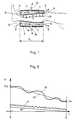
- Figure 2is an example of pressure curves.
- Figure 3is an overall diagram of the device.
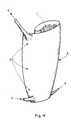
- Figure 4is an embodiment of an enclosure according to the invention.
- Figure 1is a sectional view of a portion of the device installed for example on a lower limb and therefore surrounding the entire calf of a person by a circular enclosure 2 closing around it, and a length "l" which may cover from the ankle to the base of the knee, but may be shorter or also longer length by covering the upper part of the leg.
- the hydraulic device according to the invention for the massage and the lymphatic drainage of this part 1 of the human bodycomprises an enclosure 2 which can cover said part of the body and in which a fluid 3 circulates in the direction of the desired massage and at a pressure "p "variable.
- this fluidenters through an inlet 5 located at the base of the device, ie here towards the patient's ankle; said inlet 5 can be of any type, seals around said dowel and is connected to any system for supplying said fluid; it then emerges at the upper part of the device, either here towards the base of the knee via an outlet 6, itself ensuring sealing at this level there, or is open in the ambient environment if the fluid allows it, is connected to any circuit, as shown in Figure 3, ensuring the circulation of the fluid.
- said enclosure 2is locally deformable under the sole effect of said pressure "p", so that this pressure is controllable and can act directly on the limb or part of the body concerned 1: but this does not mean not that the enclosure is generally undeformable, because it is certain that the external wall can be relatively flexible and therefore uniformly deformable in a controllable manner in the transverse direction of the circulation of the fluid, under the overall effect of the pressure; the fluid 3 circulates in the enclosure in a laminar mode, undergoing a given pressure drop in each zone of said enclosure 2 as a function of the flow rate and / or the pressure of this fluid at the inlet 5.
- This pressure dropcan be caused, because said enclosure 2 is filled with a porous medium 4 with given reduced permeability determined as a function of the cross-section of the circulation volume of the fluid 3, either because said fluid 3 is of high viscosity and fixed as a function of the section of its circulation volume in the enclosure 2, and of its adhesion against the walls along which it circulates, or has a porosity and permeability of the external wall 7 of the enclosure itself, which then lets the fluid escape through a distributed porosity or through orifices provided 19 at particular points, or over wider areas, according to a distribution circular or not, either by a combination of two or three possibilities to create any desired pressure drop.
- Said porous medium 4may consist of solid or hollow bubbles, grains of fibrous tissue sand, foam, micro tubes, laminated layers, any particles chosen according to the mechanical characteristic and the desired permeability.
- the pressure "p”is transmitted to the part of the body 1 either directly by immersion or covering of said member or part of the body by the enclosure 2 filled or not with said medium 4 or, in another embodiment, said enclosure 2 comprises a quasi-rigid external wall 7 and a flexible internal wall 8. This then covers said part of the body 1, to which it transmits the pressure "p" of the fluid 3 through its surface which only transmits and which thus isolates the skin of the person from the fluid which circulates in said enclosure.
- the external wall 7 of the enclosure 2is pre-molded to the shape of the part of the body 1. It can be personalized, relatively flexible, but while remaining rigid enough not to be deformed locally by said pressure, but flexible enough to absorb possible overpressures and allow finer adjustments to the limb's morphology.
- This external wall 7is either impermeable to the fluid circulating inside the enclosure, or permeable in a controllable manner to create an additional pressure drop effect when the fluid is compatible with the external medium, or impermeable on the major part of its surface and open at particular points 19 and whether or not connected to an external circuit.
- FIG. 2is an example of a pressure curve which can be obtained using the device according to FIGS. 1 and 3.
- the ordinaterepresents the pressure "p" prevailing at any point of said enclosure 2 and the abscissa the position of said point along the length "l" of said enclosure: the origin corresponds to the inlet 5 of the fluid in said enclosure, and the end of the curve is at the outlet of said enclosure 6: the curves shown here correspond to an inlet pressure p0 given to the same configuration of cross section of the circulation volume in said enclosure 2, which thus has a given laminar flow of fluid 3 which is constant in this volume.
- slope curvesare obtained. more or less important; thus the curve 15 can be obtained with a flow of water from a simple tap through a polyethylene foam: one can thus obtain an inlet pressure of 1.8 bar for an outlet pressure of 1.2 bar for a length "l" of the enclosure of 40 cm, while the curve 18 can be obtained by a drip rate also with water, but with an inlet pressure, for the same polyethylene foam of 0.3 bar and an outlet pressure of 0.15 bar.
- the circulation of the fluidmay indeed even be infinitesimal depending on the case.
- the outlet pressure p1can also be negative by connecting a suction system to the outlet of the enclosure 6.
- mercury tank systemswould give a curve (p0, p1) of very marked negative constant slope, related to the density of mercury.
- p0, p1very marked negative constant slope, related to the density of mercury.
- the enclosure 2may include outlet orifices 19 intermediate of the fluid 3, which orifices may be very localized and punctual on specific areas to be treated, by a local pressure variation effect, or cover a wider area, such as along a full turn of a cylindrical enclosure, when the latter surrounds a member.
- These orifices 19can be connected to an external suction system and even cause local depressions.
- the fluid 3penetrates under pressure or not into the enclosure 2, by its ends 5, 6 and leaves by the single or several intermediate orifices 19, by vacuum: more, when said enclosure 2 is placed on a surface without going around a complete part of the body, the ends 5, 6 then constitute only a single perimeter of entry or exit of fluid, and the orifice 19 can be central, placed in the precise place of an area to be treated, such as for example an edema constitutes respectively the corresponding exits or the entry: in this configuration in fact, the fluid can circulate in opposite direction, by penetrating into the enclosure by the orifice 19 and leaving by the peripheral orifice 5, 6.
- the fluid 3thus circulates from the median zones of said enclosure towards the ends, and undergoes a pressure drop therein, to ensure the desired effect of pressure variation on the part of the body to be treated, as in all the device configurations mentioned above.
- the main objectiveis in fact to perform a massage, thanks to the essential characteristic of the invention, which is to circulate a fluid 3 in an enclosure 2 in the direction of the desired massage, according to a variable pressure "p", undergoing a given pressure drop, according to the various possibilities described above in each zone of said enclosure 2, linked in particular to the flow rate and the pressure of the fluid at any entry into said enclosure.
- Itcan therefore have various forms with one or more inlets and one or more outlets defined according to the type of massage and the part of the body to be treated.
- Figure 3is an overall diagram of said device schematically showing the enclosure 2 of Figure 1; the part of the member of the human body which one wishes to massage or drain being represented by a simple rectangle 1 undergoing the pressure or the depression transmitted by the fluid 3 inside the volume 4 of said enclosure 2.
- the external wall 7 of this enclosure 2is shown here as being capable of being externally deformable by any mechanical or hydraulic system 14 of modifications to the shape of said wall 7 by reducing at certain points the cross-section of the internal volume of circulation of the fluid 3 at given points.
- the devicemay also include a compressor or a hydraulic pump 11 circulating said fluid 3 through flow control valves 12 at the inlet and at the outlet of enclosure 2, in order to obtain the desired values of flow , pressure at the inlet 5 and / or possible vacuum at the outlet 6, and / or pressure or depression in the orifice (s) 19.
- a compressor or a hydraulic pump 11circulating said fluid 3 through flow control valves 12 at the inlet and at the outlet of enclosure 2, in order to obtain the desired values of flow , pressure at the inlet 5 and / or possible vacuum at the outlet 6, and / or pressure or depression in the orifice (s) 19.
- all of the regulating valves 12 and the circulation pump 11, as well as said systems 14 for modifying the enclosureare connected to a central unit 10 external: from sensors of any type 9 of pressures located at different points pi inside said enclosure 2, the latter compares the pressures recorded by said sensors with reference values determined beforehand, according to the type of massage and desired drainage, and allows, by command to modify the parameters of the regulation valves 12 and of the circulation pump 11, to adjust the necessary flow rate, which can be measured itself by a sensor 13 located in the pumping circuit of said fluid 3.
- the circuitcan be open on the external environment at the outlet 6 of the massage enclosure 2: in this case for example, the compressor or pump 11 can be an air compressor sucking the latter into the atmosphere, the air then being released there after his massage "work"; similarly in use in a basin or swimming pool, it can be a hydraulic pump 11 which takes its fluid in this basin or swimming pool, where the person can be installed, said fluid also returning therein after it has passed through the enclosure 2 .
- the compressor or pump 11can be an air compressor sucking the latter into the atmosphere, the air then being released there after his massage "work”; similarly in use in a basin or swimming pool, it can be a hydraulic pump 11 which takes its fluid in this basin or swimming pool, where the person can be installed, said fluid also returning therein after it has passed through the enclosure 2 .
- This enclosurecan also be a simple combination of diving equipment type directly donned on the part of the body concerned.
- each of these enclosureswhich can be produced according to one of the embodiments described above, with one or more inlet openings, one or more outlet openings, at the ends of the enclosure and / or distributed along its walls, without leaving of the scope of the present invention.
- FIG. 4is an exemplary embodiment of an enclosure 2 of a device according to the invention, produced from an envelope which can be wound around the part of the body to be treated 1, with an overlap of the ends, on the one hand to ensure continuity of contact with the surface of the body, and on the other hand, to ensure the closure 20 by any suitable system, such as two ribbons, each fixed along the edge of each end and woven differently so that their surfaces grip by contact in the desired position which can therefore be adjustable, such as the so-called "VELCRO" TM closures, or by an independent outer casing.
- any suitable systemsuch as two ribbons, each fixed along the edge of each end and woven differently so that their surfaces grip by contact in the desired position which can therefore be adjustable, such as the so-called "VELCRO" TM closures, or by an independent outer casing.
- Such a form of winding deviceallows a perfect adjustment of its internal volume to that of any part of the body 1 to be treated, thanks in addition to a conical shape and / or molded in shape according to the general shape of said part 1. , and a cover without wrinkles.
- the outer wall 7 of the envelopecan be made of polyurethane or latex, and the inner part 4 of polyester foam for example.
- the fluidis then brought to the narrowest conical part, placed towards the end of a member for example, by single or multiple inlets 5, and is evacuated by a single, or also multiple outlet, 6, to the part widest conical upper.
- Such an enclosurethus meets the characteristics of the invention by allowing the application of a permanent and measurable pressure gradient, without having any displacement of the solid parts that are the walls, but simply by virtue of a flow specific of the fluid between the inlets 5 and the outlets 6.
- the circulating fluidin fact directly undergoes the pressure gradient by continuous pressure drop along any path inside the enclosure 2: there is an obstruction in the flow of the fluid inside the latter caused by the presence of a porous medium inside this enclosure 2 as described above, either by the high viscosity of the fluid used, or by a combination of these two criteria.
- a high viscosity fluidany fluid having a viscosity greater than that of water.
- the means known to dateactually use the fluid, which is often either gas or simply water, as a means of transmitting a pressure caused from the outside at a given time to mechanical systems which , attempt to massage by varying the pressure, which they receive transmitted by the fluid from the outside, over time and / or with an action restricted or limited to one section: the pressure gradient is therefore never exists at any given time or it is very coarse in separate compartments; indeed, in one case there is a pressure control in stages in compartments, and in the other, there is stealth transmission of pressure waves in the direction of small pipes or through flexible walls.
- any enclosure of the device according to the inventionin any enclosure of the device according to the invention, it is the positions of the inputs and outputs of the fluid which impose the direction of circulation and thus the direction of application of the gradient on the surface of the part of the body 1 to be treated: there is a spatial distribution of the pressure which is of prime interest for application to the venous or lymphatic network in the main application of the present invention.
- the present inventionalso makes it possible to simulate the immersion of a member in water or in a liquid of any density.
Landscapes
- Health & Medical Sciences (AREA)
- Epidemiology (AREA)
- Pain & Pain Management (AREA)
- Physical Education & Sports Medicine (AREA)
- Rehabilitation Therapy (AREA)
- Life Sciences & Earth Sciences (AREA)
- Animal Behavior & Ethology (AREA)
- General Health & Medical Sciences (AREA)
- Public Health (AREA)
- Veterinary Medicine (AREA)
- Massaging Devices (AREA)
- Percussion Or Vibration Massage (AREA)
Abstract
Description
Translated fromFrenchLa présente invention a pour objet un dispositif hydraulique pour le massage et le drainage lymphatique du corps humain.The present invention relates to a hydraulic device for massage and lymphatic drainage of the human body.
Le secteur technique de l'invention est le domaine de la fabrication d'appareils de massage utilisant la pression hydraulique.The technical sector of the invention is the field of manufacturing massage devices using hydraulic pressure.
Une des applications principale de l'invention est la réalisation de manchons ayant par exemple la forme d'un membre et que l'on peut donc enfiler sur celui-ci, afin de pouvoir assurer son massage par transmission de pression intermittente le long de sa surface.One of the main applications of the invention is the production of sleeves having, for example, the shape of a member and which can therefore be put on it, in order to be able to massage it by intermittent pressure transmission along its area.
On connaît en effet, depuis longtemps les effets bénéfiques des techniques de massage sur le corps humain, pour la circulation sanguine, l'élimination de graisses ou de cellulite, le soulagement des douleurs, la résorption d'oedèmes, l'amélioration des performances musculaires, des formes esthétiques : ces techniques étaient à l'origine manuelles, mais depuis quelques années, des appareils ont été développés pour répondre à la demande croissante de cette discipline et assurer aux personnes des possibilités de traitement régulier, de longue durée et pouvant se substituer à la main du masseur, dont la formation est longue et spécialisée, et qui ne peut être disponible que pour une seule personne à la fois.We have long known the beneficial effects of massage techniques on the human body, for blood circulation, elimination of fat or cellulite, pain relief, absorption of edema, improvement of muscle performance , aesthetic forms: these techniques were originally manual, but in recent years, devices have been developed to meet the growing demand for this discipline and provide people with opportunities for regular, long-term treatment and can replace in the hand of the masseur, whose training is long and specialized, and which can only be available for one person at a time.
Ainsi, on relève quatre types d'appareils, en écartant ceux uniquement mécaniques ou à action mécanique, et cherchant à répondre à cette demande et à ces techniques pour assurer un bon drainage lymphatique ou massage, en provoquant des variations de pression sur la peau du corps humain par un fluide :
- on relève tout d'abord les systèmes d'action globale, qui sont les plus simples et qui appliquent des pressions certes intermittentes, mais sur l'ensemble de la surface à traiter, et d'une manière uniforme : ces systèmes - sont très peu utilisés car pratiquement inefficaces car très éloignés de l'effet d'un massage;
- il a été développé alors des systèmes à plusieurs compartiments, dans lesquels on injecte un fluide sous pression intermittente et qui s'applique sur toute la surface du compartiment en contact avec la partie du corps concerné, et successivement, tout en faisant chuter la pression dans des compartiments précédents, provoquant ainsi une onde de pression dans la direction voulue, comme peut le faire effectivement la main du masseur : on relève, dans cette catégorie de systèmes, les demandes de brevets FR. 2.616.064 (SUISSA), FR. 2.617.397 (FRAJDENRASCH), FR. 2.548.017 (TISSOT) et FR. 2.511.242 (MEGOAFEK Industrial Measuring), et bien d'autres ; cependant, leur complexité de mise en oeuvre nécessite des contrôles par électrovannes des ouvertures et fermetures des compartiments, et suivant le type de fluide utilisé, soit gazeux, soit liquide, l'efficacité et la fiabilité résultante ne sont pas souvent ce qui serait souhaité, par manque de précision et par création inévitable de gradients inverses localement, ce qui est alors d'un effet très négatif.
- first of all, we note the systems of global action, which are the simplest and which apply pressures that are intermittent, but over the entire surface to be treated, and in a uniform manner: these systems - are very few used because practically ineffective because very far from the effect of a massage;
- systems with several compartments were then developed, in which a fluid is injected under intermittent pressure and which is applied over the entire surface of the compartment in contact with the part of the body concerned, and successively, while causing the pressure to drop in previous compartments, thus causing a pressure wave in the desired direction, as can be done effectively by the hand of the masseur: we note, in this category of systems, FR patent applications. 2.616.064 (SUISSA), FR. 2,617,397 (FRAJDENRASCH), FR. 2.548.017 (TISSOT) and FR. 2,511,242 (MEGOAFEK Industrial Measuring), and many others; however, their complexity of implementation requires controls by solenoid valves of the openings and closings of the compartments, and according to the type of fluid used, either gaseous or liquid, the resulting efficiency and reliability are not often what would be desired, due to a lack of precision and the inevitable creation of locally inverse gradients, which is then of a very negative effect.
Chacun a bien sûr sa particularité et sa caractéristique essentielle spécifique, qui peut améliorer l'efficacité dans un domaine ou dans un autre, et qui justifie sa brevetabilité, même si le principe est identique pour tous.Each one has of course its particularity and its specific essential characteristic, which can improve efficiency in one field or another, and which justifies its patentability, even if the principle is identical for all.
Ces systèmes sont complexes et transmettent toujours la même amplitude d'onde de pression à tous les points de la surface à masser, ce qui ne reproduit pas vraiment l'effet d'un massage qui doit s'amenuiser d'un point à un autre, tout en ayant une dégressivité linéaire, sans palier trop marqué;
- en parallèle à ces systèmes compartimentés complexes, on relève des systèmes utilisant non pas une pression hydraulique ou pneumatique par circulation de fluide, mais la pression statique d'un fluide à haute densité, essentiellement du mercure : une cuve ou manchon rigide est en effet rempli de ce fluide et le membre plongè à l'intérieur subit alors un gradient de pression parfait diminuant effectivement linéairement d'un point à l'autre; la variation alternative du niveau du fluide peut alors assurer un effet de massage. On note dans ce domaine la demande de brevet FR. 2.619.710 du 24 Août 1987 de Monsieur P. VENDEVILLE et celle FR. 2.639.222 du 18 Novembre 1988 de Monsieur Claude J. CARTIER.
- in parallel with these complex compartmentalized systems, there are systems using not hydraulic or pneumatic pressure by fluid circulation, but the static pressure of a high density fluid, essentially mercury: a rigid tank or sleeve is indeed filled of this fluid and the member plunged inside then undergoes a perfect pressure gradient effectively decreasing linearly from one point to another; the alternative variation of the fluid level can then provide a massage effect. The FR patent application is noted in this area. 2.619.710 of August 24, 1987 of Mr. P. VENDEVILLE and that FR. 2.639.222 of November 18, 1988 of Mr. Claude J. CARTIER.
Ces systèmes sont cependant très lourds à mettre en oeuvre et souvent très chers ; la pression à la partie inférieure étant très importante, peut provoquer des réactions d'inconfort et avoir des contre indications médicales; la poussée verticale d'Archimède, qui s'applique au membre immergé, étant supérieure au poids du corps, nécessite de plus des appuis de maintien sur celui-ci, rendant d'autant plus les séances inconfortables pour le patient.These systems are however very heavy to implement and often very expensive; the pressure at the bottom being very high, can cause discomfort reactions and have medical contraindications; Archimedes' vertical thrust, which applies to the submerged member, being greater than the weight of the body, requires more support supports on it, making all the more uncomfortable sessions for the patient.
Enfin, la souplesse d'utilisation est limitée par le peu de possibilités de variation de pression et par l'impératif de la position verticale du patient;
- pour tenter d'obtenir un résultat de massage efficace avec une pression intermittente sur la surface du corps, mais d'une manière plus simple tout en étant linéaire, un dernier type d'appareils s'est développé, dans lequel se situe la présente invention, à partir de ceux d'action globale, c'est-à-dire comprenant une seule enceinte, on fait varier dans celle-ci la pression en différents points de la surface de celle-ci ; on note dans ce domaine la demande de brevet FR 2.654.930 du 29 Novembre 1989 et son addition FR 2.659.549 du 14 Mars 1990 déposée par Monsieur D. PERROTIN, qui enseigne une "paroi destinée à exercer ladite pression qui est en un matériau souple et élastique, présentant un coefficient de dilatation non identique à lui-même et non constant sur toute sa périphérie". Ce système impose cependant des enceintes spécifiques avec des points de hernie provoqués aux endroits voulus et n'est donc pas adaptable d'une personne à une autre, qui aurait besoin d'un type de massage différent et ayant également une morphologie différente; de plus, le contrôle des déformations non identiques est difficile à assurer et la fiabilité de la répétition des massages est douteuse.
- in an attempt to obtain an effective massage result with intermittent pressure on the surface of the body, but in a simpler manner while being linear, a last type of apparatus has developed, in which the present invention is situated , from those of global action, that is to say comprising a single enclosure, the pressure is varied in the latter at different points on the surface thereof; we note in this area the patent application FR 2,654,930 of November 29, 1989 and its addition FR 2,659,549 of March 14, 1990 filed by Mr. D. PERROTIN, who teaches a "wall intended to exert said pressure which is made of a material flexible and elastic, with a coefficient of expansion not identical to itself and not constant over its entire periphery ". This system however imposes specific speakers with herniated points caused in the desired places and is therefore not adaptable from one person to another, who would need a different type of massage and also having a different morphology; in addition, the control of non-identical deformations is difficult to ensure and the reliability of the repetition of massages is doubtful.
On relève également dans ce type d'équipement à une seule enceinte, ceux constitués par une tuyauterie entourant la partie du corps à la manière d'un ressort, tel que l'équipement décrit dans le brevet DE.260.31.32 (ZEPPELIN) utilisant du gaz libéré dans ladite tuyauterie par intermittence et transmettant alors une onde de pression mais qui n'est pas contrôlable du fait de la détente de gaz et qui ne donne pas un effet de massage linéaire dans la direction souhaitée, comme indiqué précédemment.We also note in this type of equipment with a single enclosure, those constituted by a piping surrounding the body part in the manner of a spring, such as the equipment described in patent DE.260.31.32 (ZEPPELIN) using gas released into said piping intermittently and then transmitting a pressure wave but which is not controllable due to the expansion of gas and which does not give a linear massage effect in the desired direction, as indicated above.
Le problème posé est en effet de pouvoir transmettre une grande variété de gamme de pressions sur une partie quelconque de la surface du corps suivant des profils de variation de cette pression adaptés à chaque cas spécifique, en fonction du résultat recherché, qui soient contrôlables et répétitifs, sans moyen complexe de mise en oeuvre, et qui reproduisent au mieux les effets d'un massage manuel par ondes de pression progressives et dont l'amplitude moyenne diminue dans le sens de la propagation de cette onde.The problem posed is in fact to be able to transmit a wide variety of pressure ranges on any part of the surface of the body according to profiles of variation of this pressure adapted to each specific case, according to the desired result, which are controllable and repetitive , without complex means of implementation, and which reproduce at best the effects of a manual massage by progressive pressure waves and whose average amplitude decreases in the direction of the propagation of this wave.
Une solution au problème posé est un dispositif hydraulique pour le massage et le drainage lymphatique d'une partie du corps humain, comprenant une enceinte pouvant recouvrir ladite partie du corps, et dans laquelle un fluide circule dans tout son volume en subissant une perte de charge décroissante liée en particulier au débit et à la pression du fluide à l'entrée de ladite enceinte; laquelle enceinte comprend des zones, est apte à couvrir toute la surface de la partie du corps, et est indéformable localement sous le seul effet de la pression "p", à laquelle circule ledit fluide spatialement dans le sens du massage souhaité; laquelle enceinte est remplie d'un milieu poreux de perméabilité réduite donné, déterminé en fonction de la section du volume de circulation du fluide et dont la caractérisique de perte de charge imposée au fluide dans chaque zone de ladite enceinte est linéairement continue dans la direction de circulation du fluideOne solution to the problem posed is a hydraulic device for massage and lymphatic drainage of a part of the human body, comprising an enclosure which can cover said part of the body, and in which a fluid circulates in its entire volume undergoing a pressure drop. decreasing, linked in particular to the flow and pressure of the fluid at the inlet of said enclosure; which enclosure comprises zones, is capable of covering the entire surface of the part of the body, and is locally non-deformable under the sole effect of the pressure "p", at which said fluid circulates spatially in the direction of the desired massage; which enclosure is filled with a porous medium of given reduced permeability, determined as a function of the cross-section of the volume of circulation of the fluid and whose characteristic of pressure drop imposed on the fluid in each zone of said enclosure is linearly continuous in the direction of fluid circulation
Ledit fluide peut être un fluide de viscosité élevé, fixée en fonction de la section de son volume de circulation dans l'enceinte et de son adhérence contre les parois le long desquelles il circule ; dans un mode de réalisation, les parois extérieures de l'ensemble sont perméables audit fluide.Said fluid may be a fluid of high viscosity, fixed as a function of the section of its circulation volume in the enclosure and of its adhesion against the walls along which it circulates; in one embodiment, the external walls of the assembly are permeable to said fluid.
Dans un mode préférentiel de réalisation, la paroi externe de l'enceinte est déformable volontairement extérieurement, par tout moyen, afin de modifier la section du volume interne de circulation du fluide en des points donnés.In a preferred embodiment, the external wall of the enclosure is voluntarily deformable externally, by any means, in order to modify the section of the internal volume of circulation of the fluid at given points.
Un autre objectif de la présente invention est obtenu par un dispositif qui comporte des capteurs de pression à l'intérieur de ladite enceinte, reliés à une unité centrale externe, qui compare lesdites pressions relevées à des valeurs de consigne, déterminée préalablement en fonction du type de massage voulu, et qui permet la régulation du débit et de la pression, à l'entrée du fluide dans l'enceinte pour obtenir lesdites valeurs de consigne.Another objective of the present invention is obtained by a device which includes pressure sensors inside said enclosure, connected to an external central unit, which compares said recorded pressures with reference values, determined beforehand according to the type desired massage, and which allows the regulation of the flow rate and the pressure, at the entry of the fluid into the enclosure to obtain said set values.
Le résultat de nouveaux dispositifs hydrauliques pour le massage et le drainage lymphatique du corps humain, qui répond au problème posé et supprime les inconvénients relevés dans les systèmes existants à ce jour.The result of new hydraulic devices for massage and lymphatic drainage of the human body, which responds to the problem posed and eliminates the drawbacks noted in existing systems to date.
En effet, la présente invention est basée sur le principe hydraulique connu des pertes de charge produites dans le sens de la circulation d'un fluide liquide, gazeux, plus ou moins visqueux, s'écoulant dans un milieu à perméabilité plus ou moins réduite suivant ladite viscosité du fluide.In fact, the present invention is based on the known hydraulic principle of the pressure losses produced in the direction of circulation of a liquid, gaseous, more or less viscous fluid, flowing in a medium with more or less reduced permeability according to said viscosity of the fluid.
Le dispositif suivant l'invention permet d'appliquer ce principe hydraulique aux techniques de massage du corps humain, en contrôlant ces pertes de charge, afin d'obtenir sur la partie du corps concerné une pression variable et linéairement dégressive dans le sens souhaité, et le principe même permet une très grande variation des effets.The device according to the invention makes it possible to apply this hydraulic principle to massage techniques of the human body, by controlling these pressure drops, in order to obtain on the part of the body concerned a variable and linearly decreasing pressure in the desired direction, and the very principle allows a very large variation of the effects.
Les champs d'application sont donc innombrables puisque d'une pression statique pour un débit nul donc sans variation linéaire, très petite ou très puissante, on peut faire varier le débit du fluide et par ajustement des pressions de départ et d'arrivée sur une distance quelconque, obtenir des gradients de pression faibles ou violents. Les pressions pouvant subir des modulations en intensité à des fréquences variables, allant de fractions d'hertz à plusieurs milieux d'hertz, créant ainsi des massages à longue période ou des vibrations.The fields of application are therefore innumerable since of a static pressure for a zero flow therefore without linear variation, very small or very powerful, one can vary the flow of the fluid and by adjusting the pressures of departure and arrival on a any distance, obtain weak or violent pressure gradients. The pressures being able to undergo modulations in intensity at variable frequencies, going from fractions of hertz to several media of hertz, thus creating massages with long period or vibrations.
De plus, par modification volontaire de la paroi externe de l'enceinte dans laquelle circule le fluide, on peut augmenter ou diminuer les zones de plus forte pression par augmentation ou diminution de la section de passage du fluide, et avoir ainsi un profil de pressions à la demande suivant le type de massage souhaité : cette modification de parois pouvant être réglée pour chaque cas, ou pouvant même être modulée en cours d'opération, avec en combinaison, une modification possible de la pression d'entrée et du débit du fluide, on obtient des profils de pression non plus seulement dégressivement linéaires en moyenne, mais également suivant toute courbe que l'on peut souhaiter.In addition, by voluntary modification of the external wall of the enclosure in which the fluid circulates, it is possible to increase or decrease the zones of higher pressure by increasing or decreasing the cross section of the fluid, and thus having a pressure profile. on request according to the type of massage desired: this modification of walls can be adjusted for each case, or can even be modulated during operation, with in combination, a possible modification of the inlet pressure and the flow rate of the fluid , pressure profiles are no longer only degressively linear on average, but also along any curve that may be desired.
Dans le domaine médical, une enveloppe sur une partie quelconque du corps pourra ainsi transmettre une grande quantité d'effets de pression, qu'elles soient très légères tel qu'effleurement, glissement, drainage etc... ou très fortes comme pour des massages, et suivant tout profil et fréquence voulu, permettant des techniques d'action très larges, tant superficielles qu'en profondeur sur la partie du corps considérée, dans un objectif de drainage lymphatique, d'amélioration de la circulation du sang etc.....In the medical field, an envelope on any part of the body will thus be able to transmit a large amount of pressure effects, whether they are very light such as touch, sliding, drainage etc ... or very strong as for massages , and according to any desired profile and frequency, allowing very broad action techniques, both superficial and deep on the part of the body considered, with a view to lymphatic drainage, improvement of blood circulation, etc.
On peut ainsi, d'une part obtenir les mêmes effets que les systèmes cités précédemment dans les techniques actuelles et connues mais limités dans un seul type d'action tels que le sont les systèmes à mercure, les systèmes d'action globale ou ceux à coefficient de dilatation non identique, d'autre part, améliorer les effets des systèmes à compartiments par une linéarité de pression et non une variation en escalier, tout en élargissant les possibilités à d'autres cas qui ne peuvent pas être résolus par les systèmes actuels.It is thus possible, on the one hand, to obtain the same effects as the systems cited above in current and known techniques but limited to a single type of action such as are mercury systems, global action systems or those to coefficient of expansion not identical, on the other hand, improving the effects of systems with compartments by a linearity of pressure and not a variation in staircase, while widening the possibilities to other cases which cannot be solved by current systems .
De plus, l'ensemble du circuit est contrôlable, donc assure une fiabilité et une répétitivité des actions, tout en ne nécessitant qu'une mise en oeuvre simple et légère.In addition, the entire circuit is controllable, thus ensuring reliability and repeatability of actions, while requiring only a simple and light implementation.
On pourrait citer d'autres avantages de la présente invention, mais ceux cités ci-dessus en montrent déjà suffisamment pour en démontrer la nouveauté et l'intérêt.We could cite other advantages of the present invention, but those mentioned above already show enough to demonstrate its novelty and interest.
La description et les figures ci-après représentent un exemple de réalisation de l'invention, mais n'ont aucun caractère limitatif : d'autres réalisations sont possibles dans le cadre de la portée et de l'étendue de la présente invention, en particulier en changeant la forme de base de l'enceinte qui peut s'adapter à toute partie du corps, quelle qu'elle soit, tel qu'une partie d'un membre, un pied, une main, un abdomen, un membre entier etc..., mais également on peut imaginer d'autres applications dans d'autres domaines que le médical, sur toute surface sur laquelle on veut appliquer des variations de pression contrôlées et contrôlables suivant un profil donné.The description and the figures below represent an exemplary embodiment of the invention, but are in no way limiting: other embodiments are possible within the scope and scope of the present invention, in particular by changing the basic shape of the enclosure which can adapt to any part of the body, whatever it is, such as a part of a member, a foot, a hand, an abdomen, a whole member etc. ..., but also one can imagine other applications in fields other than the medical field, on any surface on which one wants to apply controlled and controllable pressure variations according to a given profile.
La figure 1 est une vue en coupe d'une partie du dispositif sur un membre inférieur.Figure 1 is a sectional view of part of the device on a lower member.
La figure 2 est un exemple de courbes de pressions.Figure 2 is an example of pressure curves.
La figure 3 est un schéma d'ensemble du dispositif.Figure 3 is an overall diagram of the device.
La figure 4 est un exemple de réalisation d'une enceinte suivant l'invention.Figure 4 is an embodiment of an enclosure according to the invention.
La figure 1 est une vue en coupe d'une partie du dispositif installé par exemple sur un membre inférieur et donc entourant l'ensemble du mollet d'une personne par une enceinte 2 circulaire se refermant autour de celui-ci, et d'une longueur "l" pouvant couvrir depuis la cheville jusqu'à l'embase du genou, mais pouvant être de longueur plus courte ou également plus longue en venant recouvrir la partie supérieure de la jambe.Figure 1 is a sectional view of a portion of the device installed for example on a lower limb and therefore surrounding the entire calf of a person by a
Le dispositif hydraulique suivant l'invention pour le massage et le drainage lymphatique de cette partie 1 du corps humain comprend une enceinte 2 pouvant recouvrir ladite partie du corps et dans laquelle un fluide 3 circule dans le sens du massage souhaité et à une pression "p" variable. Pour cela, ce fluide pénètre par une entrée 5 située à la base du dispositif, soit ici vers la cheville du patient; ladite entrée 5 peut être de tout type, assure l'étanchéité autour de ladite cheville et est raccordée à tout système d'alimentation dudit fluide; celui-ci ressort ensuite à la partie supérieure du dispositif, soit ici vers l'embase du genou par une sortie 6, elle-même assurant l'étanchéité à ce niveau là et, soit ouverte dans le milieu ambiant si le fluide le permet, soit raccordée à tout circuit, tel que représenté sur la figure 3, assurant la circulation du fluide.The hydraulic device according to the invention for the massage and the lymphatic drainage of this
Dans la présente invention, ladite enceinte 2 est indéformable localement sous le seul effet de ladite pression "p", de façon à ce que cette pression soit contrôlable et puisse agir directement sur le membre ou la partie du corps concernée 1 : mais cela ne signifie pas que l'enceinte est globalement indéformable, car il est certain que la paroi externe peut être relativement souple et donc uniformément déformable d'une manière contrôlable dans le sens transversal de la circulation du fluide, sous l'effet global de la pression ; le fluide 3 circule dans l'enceinte suivant un mode laminaire en subissant une perte de charge donnée en chaque zone de ladite enceinte 2 en fonction du débit et/ou de la pression de ce fluide à l'entrée 5.In the present invention, said
Cette perte de charge peut être provoquée, parce que ladite enceinte 2 est remplie d'un milieu 4 poreux à perméabilité réduite donnée déterminée en fonction de la section du volume de circulation du fluide 3, soit parce que ledit fluide 3 est de viscosité élevée et fixée en fonction de la section de son volume de circulation dans l'enceinte 2, et de son adhérence contre les parois le long desquelles il circule, soit a une porosité et perméabilité de la paroi externe 7 de l'enceinte elle-même, qui laisse alors s'échapper du fluide par une porosité répartie ou par des orifices prévus 19 en des points particuliers, ou sur des zones plus larges, suivant une répartition circulaire ou non, soit par une combinaison de deux ou de trois possibilités pour créer toute perte de charge voulue.This pressure drop can be caused, because said
Ledit milieu poreux 4 peut être constitué de bulles pleines ou creuses, de grains de sable de tissus fibreux, de mousse, de micro tubes, de couches feuilletées, de toutes particules choisies en fonction de la caractéristique mécanique et de la perméabilité recherchée.Said
La pression "p" est transmise à la partie du corps 1 soit directement par immersion ou recouvrement dudit membre ou partie du corps par l'enceinte 2 remplie ou non dudit milieu 4 ou, dans un autre mode de réalisation, ladite enceinte 2 comporte une paroi externe 7 quasi rigide et une paroi interne 8 souple. Celle-ci recouvre alors ladite partie du corps 1, à laquelle elle transmet la pression "p" du fluide 3 à travers sa surface qui ne fait que transmettre et qui isole ainsi la peau de la personne du fluide qui circule dans ladite enceinte.The pressure "p" is transmitted to the part of the
De manière préférentielle, la paroi externe 7 de l'enceinte 2 est prémoulée à la forme de la partie du corps 1. Elle peut être personnalisée, relativement souple, mais tout en restant suffisamment rigide pour ne pas être déformée localement par ladite pression, mais suffisamment souple pour absorber d'éventuelles surpressions et permettre des ajustements plus fins à la morphologie du membre. Cette paroi extérieure 7 est soit imperméable au fluide circulant à l'intérieur de l'enceinte, soit perméable d'une manière contrôlable pour créer un effet de perte de charge supplémentaire quand le fluide est compatible avec le milieu extérieur, soit imperméable sur la majeure partie de sa surface et ouverte en des points 19 particuliers et reliés ou non à un circuit externe.Preferably, the
La figure 2 est un exemple de courbe pression que l'on peut obtenir grâce au dispositif suivant les figures 1 et 3.FIG. 2 is an example of a pressure curve which can be obtained using the device according to FIGS. 1 and 3.
En ordonnées il est représenté la pression "p" régnant en tout point de ladite enceinte 2 et en abscisses la position dudit point le long de la longueur "l" de ladite enceinte : l'origine correspond à l'entrée 5 du fluide dans ladite enceinte, et l'extrémité de la courbe est à la sortie de ladite enceinte 6 : les courbes représentées ici correspondent à une pression d'entrée p0 donnée à une même configuration de section du volume de circulation dans ladite enceinte 2, qui a ainsi un débit laminaire de fluide 3 donné et constant dans ce volume.The ordinate represents the pressure "p" prevailing at any point of said
En faisant varier la pression d'entrée p0, la section de passage dudit fluide à différents points de l'enceinte 2, ainsi que le débit du fluide en relation avec la pression p0 d'entrée, on peut obtenir à un instant donné "t" des courbes différentes de celle de la figure 2, ayant des allures diverses en fonction de ce que l'on souhaite, mais toujours linéaires et continues dans leur forme générale.By varying the inlet pressure p0, the cross section of said fluid at different points of the
Sur cette figure 2, on regarde simplement le devenir d'une pression p0 à l'entrée 5 jusqu'à la sortie 6 pour un état stationnaire dans l'ensemble du volume, pour simplifier le raisonnement.In this FIG. 2, we simply look at the fate of a pressure p0 at the
Les courbes 15 et 18 sont alors des courbes obtenues pour un régime de débit laminaire donné avec des pressions d'entrée p0 constantes et p1 de sortie 6 également constantes, la perte de charge
En fonction de la possibilité de variation de cette perméabilité telle que définie précédemment par variation du volume de la section de passage ou par changement de viscosité du fluide 3, ou par variation du débit pour un même fluide donné 3, on obtient des courbes de pentes plus ou moins importantes; ainsi la courbe 15 peut être obtenue avec un écoulement d'eau d'un simple robinet à travers une mousse de polyéthylène : on peut obtenir ainsi une pression d'entrée de 1,8 bar pour une pression de sortie de 1,2 bar pour une longueur "l" de l'enceinte de 40 cm, alors que la courbe 18 peut être obtenue par un débit de goutte à goutte également avec de l'eau, mais avec une pression d'entrée, pour la même mousse de polyéthylène de 0,3 bar et une pression de sortie de 0,15 bar. La circulation du fluide peut en effet même être infinitésimale suivant le cas.Depending on the possibility of variation of this permeability as defined above by variation of the volume of the passage section or by change of viscosity of the
En changeant la densité de perméabilité de la mousse, ou l'eau par un autre fluide différent de viscosité, ou par porosité de la paroi 7, on peut ainsi obtenir toute courbe p0, p1 avec des pentes plus ou moins importantes et une pression p0 d'entrée également plus ou moins élevée, de façon à obtenir la variation de pression linéaire souhaitée.By changing the density of permeability of the foam, or the water by another fluid different in viscosity, or by porosity of the
De plus, en faisant varier la pression d'entrée p0 suivant une séquence de type sinusoïdale, avec une variation relativement lente, on peut obtenir une courbe de type 16, alors qu'avec une fréquence de variation de pression beaucoup plus élevée, on peut obtenir une courbe 17 avec des variations beaucoup plus hachée ressemblant plus à de la vibration qu'à du massage. La pression de sortie p1 peut être également négative en branchant un système d'aspiration à la sortie de l'enceinte 6.In addition, by varying the inlet pressure p0 in a sinusoidal type sequence, with a relatively slow variation, one can obtain a
Par comparaison, des systèmes de type cuves à mercure donneraient une courbe (p0, p1) de pente constante négative très marquée, liée à la densité du mercure. On peut obtenir également une courbe de ce type et même encore plus négative avec un dispositif suivant l'invention, superposant les trois effets de perte de charge : en augmentant bien sûr la viscosité, en diminuant la perméabilité du milieu interne dans l'enceinte du dispositif et en faisant s'échapper du fluide au fur et à mesure de sa circulation au travers de l'enceinte.By comparison, mercury tank systems would give a curve (p0, p1) of very marked negative constant slope, related to the density of mercury. One can also obtain a curve of this type and even even more negative with a device according to the invention, superimposing the three effects of pressure drop: by of course increasing the viscosity, by decreasing the permeability of the internal medium in the enclosure of the device and by escaping the fluid as it circulates through the enclosure.
Comme indiqué sur la figure 1, l'enceinte 2 peut comporter des orifices de sortie 19 intermédiaires du fluide 3, lesquels orifices peuvent être très localisés et ponctuels sur des zones spécifiques à traiter, par un effet de variation locale de pression, ou couvrir une zone plus étendue, tel que le long d'un tour complet d'une enceinte cylindrique, quand celle-ci entoure un membre. Ces orifices 19 peuvent être reliés à un système d'aspiration extérieur et provoquer même des dépressions locales. Ainsi, on peut même réaliser des dispositifs suivant l'invention, dans lesquels le fluide 3 pénètre sous pression ou non dans l'enceinte 2, par ses extrémités 5, 6 et sorte par le seul ou plusieurs orifices intermédiaires 19, par dépression : de plus, quand ladite enceinte 2 est posée sur une surface sans faire le tour d'une partie complète du corps, les extrémités 5, 6 ne constituent alors qu'un seul périmètre d'entrée ou de sortie de fluide, et l'orifice 19 peut être central, placé à l'endroit précis d'une zone à traiter, tel que par exemple un oedème constitue respectivement la sorties ou l'entrée correspondantes : dans cette configuration en effet, le fluide peut circuler en sens inverse, en pénétrant dans l'enceinte par l'orifice 19 et en sortant par l'orifice périphérique 5, 6.As indicated in FIG. 1, the
Dans la configuration de la figure 1, il peut être également envisagé de faire circuler le fluide en le faisant pénétrer dans l'enceinte 2 par lesdits orifices 19 répartis le long de ladite enceinte, et sortir par les orifices d'extrémité 5, 6, qui sont alors tous deux des orifices de sortie : le fluide 3 circule ainsi depuis des zones médianes de ladite enceinte vers les extrémités, et subit dans celle-ci une perte de charge, pour assurer l'effet voulu de variation de pression sur la partie du corps à traiter, comme dans toutes les configurations de dispositif citées précédemment.In the configuration of FIG. 1, it can also be envisaged to circulate the fluid by making it enter the
Dans tous ces modes de réalisation, l'objectif principal est en effet d'effectuer un massage, grâce à la caractéristique essentielle de l'invention, qui est de faire circuler un fluide 3 dans une enceinte 2 dans le sens du massage souhaité, suivant une pression "p" variable, en subissant une perte de charge donnée, suivant les diverses possibilités décrites précédemment en chaque zone de ladite enceinte 2, liée en particulier au débit et à la pression du fluide à toute entrée dans ladite enceinte. Celle-ci peut donc avoir des formes variées avec une ou plusieurs entrées et une ou plusieurs sorties définies en fonction du type de massage et de la partie du corps à traiter.In all of these embodiments, the main objective is in fact to perform a massage, thanks to the essential characteristic of the invention, which is to circulate a
La figure 3 est un schéma d'ensemble dudit dispositif reprenant schématiquement l'enceinte 2 de la figure 1; la partie du membre du corps humain que l'on veut masser ou drainer étant représenté par un simple rectangle 1 subissant la pression ou la dépression transmise par le fluide 3 à l'intérieur du volume 4 de ladite enceinte 2.Figure 3 is an overall diagram of said device schematically showing the
La paroi externe 7 de cette enceinte 2 est représentée ici comme pouvant être déformable extérieurement par tout système 14 mécanique ou hydraulique de modifications de la forme de ladite paroi 7 par diminution en certains points de la section de passage du volume interne de circulation du fluide 3 en des points donnés.The
Le dispositif peut comprendre par ailleurs un compresseur ou une pompe hydraulique 11 faisant circuler ledit fluide 3 à travers de vannes de régulation du débit 12 à l'entrée et à la sortie de l'enceinte 2, afin d'obtenir les valeurs désirées de débit, de pression à l'entrée 5 et/ou de dépression éventuelle à la sortie 6, et/ou de pression ou de dépression dans le ou les orifices 19. Afin de rendre automatique l'ensemble du dispositif pour permettre une sécurité et une fiabilité de répétition de la technique de massage ou de drainage souhaitée, l'ensemble des vannes de régulation 12 et de la pompe de circulation 11, ainsi que desdits systèmes 14 de modification de l'enceinte sont reliés à une unité centrale 10 externe : à partir de capteurs de tout type 9 de pressions situés en différents points pi à l'intérieur de ladite enceinte 2, celle-ci compare les pressions relevées par lesdits capteurs à des valeurs de consigne déterminées préalablement, en fonction du type de massage et de drainage voulu, et permet par commande de modification des paramètres des vannes de régulation 12 et de la pompe de circulation 11, d'ajuster le débit nécessaire, pouvant être mesuré lui-même par un capteur 13 situé dans le circuit de pompage dudit fluide 3.The device may also include a compressor or a
A partir de cette configuration et d'un schéma tel que représenté sur cette figure 3, d'autres modules peuvent être rajoutés tel que le contrôle de la pression en différents autres endroits, ainsi que la mesure de la température du fluide. L'ensemble peut être mis également en oeuvre en position quelconque, horizontale ou verticale, ainsi qu'en apesanteur par immersion par exemple de l'enceinte 2 autour du membre concerné 1, car l'ensemble étant hydraulique, n'est pas du tout influencé par la position de cette enceinte.From this configuration and a diagram as shown in this figure 3, other modules can be added such as the pressure control in different other places, as well as the measurement of the temperature of the fluid. The assembly can also be implemented in any position, horizontal or vertical, as well as in weightlessness by immersion for example of the
Dans un mode de réalisation simplifié, le circuit peut être ouvert sur le milieu extérieur à la sortie 6 de l'enceinte 2 de massage : en ce cas par exemple, le compresseur ou pompe 11 peut être un compresseur d'air aspirant celui-ci dans l'atmosphère, l'air y étant ensuite rejeté après son "travail" de massage; de même dans une utilisation en bassin ou piscine, ce peut être une pompe hydraulique 11 qui prend son fluide dans ce bassin ou piscine, où la personne peut être installée, ledit fluide revenant également dans celui-ci après son passage dans l'enceinte 2.In a simplified embodiment, the circuit can be open on the external environment at the
Cette enceinte peut être aussi une simple combinaison de type équipement de plongée directement enfilée sur la partie du corps concernée.This enclosure can also be a simple combination of diving equipment type directly donned on the part of the body concerned.
Ceci ouvre énormément l'horizon des applications possibles, depuis des systèmes standards bas de gamme, pressurisé éventuellement à la main et transportable, jusqu'à des applications beaucoup plus complexes, moulées, pilotées par ordinateur tel que représenté sur cette figure 3.This opens up a wide range of possible applications, from low-end standard systems, possibly pressurized by hand and transportable, to much more complex, molded, computer-controlled as shown in this figure 3.
De plus, il peut être combiné différentes enceintes, soit les unes derrière les autres, afin de multiplier les possibilités d'action dans le sens longitudinal de la partie du corps à traiter, soit indépendantes pour traiter plusieurs parties du corps simultanément, chacune de ces enceintes pouvant être réalisées suivant un des modes de réalisation décrit précédemment, avec un ou plusieurs orifices d'entrée, un ou plusieurs orifices de sortie, aux extrémités de l'enceinte et/ou répartis le long de ses parois, et cela, sans sortir du cadre de la présente invention.In addition, it can be combined different enclosures, either one behind the other, in order to multiply the possibilities of action in the longitudinal direction of the part of the body to be treated, or independent to treat several parts of the body simultaneously, each of these enclosures which can be produced according to one of the embodiments described above, with one or more inlet openings, one or more outlet openings, at the ends of the enclosure and / or distributed along its walls, without leaving of the scope of the present invention.
Enfin la figure 4 est un exemple de réalisation d'une enceinte 2 d'un dispositif suivant l'invention, réalisée à partir d'une enveloppe pouvant s'enrouler autour de la partie du corps à traiter 1, avec un recouvrement des extrémités, d'une part pour assurer une continuité de contacts avec la surface du corps, et d'autre part, assurer la fermeture 20 par tout système adapté, tel que deux rubans, fixés chacun le long du bord de chaque extrémité et tissés différemment pour que leurs surfaces s'agrippent par contact dans la position voulue qui peut donc être réglable, tel que les fermetures dite "VELCRO"™, ou par une enveloppe extérieure indépendante.Finally, FIG. 4 is an exemplary embodiment of an
Une telle forme de dispositif d'enroulement permet un ajustement parfait de son volume intérieur à celui de toute partie du corps 1 à traiter, grâce de plus, à une forme conique et/ou moulée en forme suivant l'allure générale de ladite partie 1, et à un recouvrement sans plis.Such a form of winding device allows a perfect adjustment of its internal volume to that of any part of the
La paroi extérieure 7 de l'enveloppe peut être réalisée en polyuréthanne ou en latex, et la partie intérieure 4 en mousse polyester par exemple.The
Le fluide est alors amené à la partie conique la plus étroite, placée vers l'extrémité d'un membre par exemple, par des entrées unique ou multiple 5, et est évacué par une sortie unique, ou multiple également, 6, à la partie supérieure conique la plus large.The fluid is then brought to the narrowest conical part, placed towards the end of a member for example, by single or
Une telle enceinte répond ainsi aux caractéristiques de l'invention en permettant l'application d'un gradient de pression permanent et mesurable, sans avoir aucun déplacement des parties solides que sont les parois, mais grâce simplement à un écoulement spécifique du fluide entre les entrées 5 et les sorties 6. Le fluide circulant subit en effet directement le gradient de pression par perte de charge continue le long d'un parcours quelconque à l'intérieur de l'enceinte 2 : il y a obstruction à l'écoulement du fluide à l'intérieur de celle-ci provoquée par la présence d'un milieu poreux à l'intérieur de cette enceinte 2 tel que décrit précédemment, soit par viscosité importante du fluide utilisé, soit par une association de ces deux critères.Such an enclosure thus meets the characteristics of the invention by allowing the application of a permanent and measurable pressure gradient, without having any displacement of the solid parts that are the walls, but simply by virtue of a flow specific of the fluid between the
Nous appelons dans la présente invention un fluide de viscosité élevé tout fluide ayant une viscosité supérieure à celle de l'eau.In the present invention, we call a high viscosity fluid any fluid having a viscosity greater than that of water.
Nous rappelons que les moyens connus à ce jour utilisent en fait le fluide, qui est souvent soit du gaz, soit simplement de l'eau, comme moyen de transmettre une pression provoquée de l'extérieur à un moment donné à des systèmes mécaniques qui eux, tentent de faire un massage par variation de la pression, qu'ils reçoivent transmise par le fluide de l'extérieur, dans le temps et/ou avec une action restreinte ou limitée à une section : le gradient de pression n'est donc en fait jamais existant à un instant donné ou bien il est très grossier dans des compartiments séparés; en effet, dans un cas il y a un contrôle de la pression par paliers dans des compartiments, et dans l'autre, il y a transmission furtive d'ondes de pression dans la direction des petits tuyaux ou à travers des parois souples.We recall that the means known to date actually use the fluid, which is often either gas or simply water, as a means of transmitting a pressure caused from the outside at a given time to mechanical systems which , attempt to massage by varying the pressure, which they receive transmitted by the fluid from the outside, over time and / or with an action restricted or limited to one section: the pressure gradient is therefore never exists at any given time or it is very coarse in separate compartments; indeed, in one case there is a pressure control in stages in compartments, and in the other, there is stealth transmission of pressure waves in the direction of small pipes or through flexible walls.
Comme sur cette figure 4, dans toute enceinte du dispositif suivant l'invention, ce sont les positions des entrées et sorties du fluide qui imposent la direction de circulation et ainsi la direction d'application du gradient sur la surface de la partie du corps 1 à traiter : il y a une répartition spatiale de la pression qui a un intérêt de premier ordre pour l'application sur le réseau veineux ou lymphatique dans l'application principale de la présente invention. La présente invention permet également de simuler l'immersion d'un membre dans de l'eau ou dans un liquide de densité quelconque.As in this FIG. 4, in any enclosure of the device according to the invention, it is the positions of the inputs and outputs of the fluid which impose the direction of circulation and thus the direction of application of the gradient on the surface of the part of the
Claims (10)
- Hydraulic device for lymphatic drainage and massage of a part (1) of the human body, the device comprising an enclosure (2) capable of covering said part of the body, and in which a fluid (3) circulates throughout its volume, being subjected to headloss tied in particular to the flow rate and to the pressure of the fluid at the inlet (5) of sad enclosure, which enclosure (2) comprises zones capable of covering the entire surface of said part (1) of the body, the device being characterized in that said enclosure (2) is undeformable locally under the sole effect of the pressurep at which said fluid (3) circulates spatially in the desired massage direction, which enclosure is filled with a porous medium (4) of given low permeability, determined as a function of the section of the circulation volume of the fluid (3) and of which the headloss characteristic imposed to the fluid in each zone of said enclosure (2) is linearly continuous in the fluid circulation direction.
- Device according to claim 1, characterized in that said fluid (3) is a fluid of high viscosity, and is determined as a function of the section of its circulation volume inside the enclosure (2) and of its adhesion against the walls along which it circulates.
- Device according to any one of claims 1 to 2, characterized in that said enclosure (2) comprises a practically rigid outside wall (7) and a flexible inside wall (8) that cover said part of the body (1) to which it transmits the pressurep of the fluid (3).
- Device according to any one of claims 1 to 3, characterized in that the outside wall (7) of the enclosure (2) is premolded to the shape of said part of the body (1).
- Device according to any one of claims 1 to 4, characterized in that the outside wall (7) of the enclosure (2) is externally deformable by any means, in order to modify the section of the inside volume through which the fluid (3) circulates at given points.
- Device according to any one of claims 1 to 5, characterized in that it comprises pressure sensors (9) inside said enclosure (2), connected to an external central unit (10) that compares the recorded pressures (pi) with set reference values, determined beforehand as a function of the desired type of massage, and that enable the flow rate and the pressure at the fluid inlet (5) into the enclosure (2) to be regulated so as to obtain said reference values.
- Device according to any one of claims 1 to 6, characterized in that said enclosure (2) comprises intermediate outlet orifices (19) for the fluid (3), which orifices may be very localized on special zones to be treated by a local pressure variation effect, or may cover a more extended zone such as around a complete circumference of a cylindrical enclosure for a limb.
- Device according to any one of claims 1 to 6, characterized in that said enclosure (2) may comprise intermediate inlet orifices (19) for the fluid (3), which orifices may be localized in special treatment zones.
- Device according to any one of claims 1 to 8, characterized in that said porous medium (4) is constituted of laminated layers.
- Hydraulic device for the massage and lymphatic drainage of a part (1) of the human body, characterized in that it comprises different separate enclosures (2) according to any one of claims 1 to 9, placed one behind the others, for treating said part of the body.
Applications Claiming Priority (3)
| Application Number | Priority Date | Filing Date | Title |
|---|---|---|---|
| FR9115473 | 1991-12-06 | ||
| FR9115473AFR2684547B1 (en) | 1991-12-06 | 1991-12-06 | HYDRAULIC DEVICE FOR LYMPHATIC MASSAGE AND DRAINAGE OF THE HUMAN BODY. |
| PCT/FR1992/001112WO1993010739A1 (en) | 1991-12-06 | 1992-11-30 | Hydraulic massage and lymphatic drainage device |
Publications (2)
| Publication Number | Publication Date |
|---|---|
| EP0615434A1 EP0615434A1 (en) | 1994-09-21 |
| EP0615434B1true EP0615434B1 (en) | 1996-04-24 |
Family
ID=9420003
Family Applications (1)
| Application Number | Title | Priority Date | Filing Date |
|---|---|---|---|
| EP93901800AExpired - LifetimeEP0615434B1 (en) | 1991-12-06 | 1992-11-30 | Hydraulic massage and lymphatic drainage device |
Country Status (5)
| Country | Link |
|---|---|
| US (1) | US5672148A (en) |
| EP (1) | EP0615434B1 (en) |
| DE (1) | DE69210258T2 (en) |
| FR (1) | FR2684547B1 (en) |
| WO (1) | WO1993010739A1 (en) |
Families Citing this family (30)
| Publication number | Priority date | Publication date | Assignee | Title |
|---|---|---|---|---|
| DE19524380C2 (en)* | 1995-07-04 | 1997-10-09 | Steinweg Friedhelm Dr Med | Massage device, in particular for use in decongestive therapy |
| US6027464A (en)* | 1996-03-28 | 2000-02-22 | Dahlquist; Daryl Leroy | Sleeping and therapy system with a person hydraulically supported by immersion in water |
| WO2002058618A1 (en)* | 1998-03-16 | 2002-08-01 | Brotz Gregory R | Therapeutic stimulatory massage device |
| US6539946B2 (en) | 1998-11-13 | 2003-04-01 | Rudolf Weyergans | Alternating pressure method for cellulite reduction |
| FR2807025B1 (en)* | 2000-03-31 | 2002-10-31 | Eastman Kodak Co | DEVICE FOR CONTACTING A DEFINED QUANTITY OF A TREATMENT MATERIAL WITH AN AQUEOUS SOLUTION TO BE TREATED AND METHOD FOR TREATING AN AQUEOUS SOLUTION |
| WO2001080942A1 (en) | 2000-04-25 | 2001-11-01 | Harumi Naganuma | Noninvasive detection and activation of the lymphatic system in treating disease and alleviating pain |
| US7771376B2 (en) | 2000-06-02 | 2010-08-10 | Midtown Technology Ltd. | Inflatable massage garment |
| US7044924B1 (en) | 2000-06-02 | 2006-05-16 | Midtown Technology | Massage device |
| USD452570S1 (en) | 2001-01-12 | 2001-12-25 | Salton, Inc. | Control unit |
| EP1509176B1 (en)* | 2002-05-23 | 2006-08-23 | Otto Bock HealthCare, LP | Pulsating pressure chamber in a prosthetic limb |
| US7306568B2 (en)* | 2003-01-06 | 2007-12-11 | Richard Diana | Method and device for treatment of edema |
| US20050004419A1 (en)* | 2003-07-03 | 2005-01-06 | Jacob Lavee | Hydraulic assist method and system |
| WO2005039478A1 (en)* | 2003-10-24 | 2005-05-06 | Hydroco (Australia) Pty Ltd | Massage apparatus |
| ES2239538B1 (en)* | 2004-03-08 | 2006-11-01 | Electromedicarin, S.A. | PRESOTHERAPY TEAM. |
| GB0413531D0 (en)* | 2004-06-17 | 2004-07-21 | Ross Weir Designs Ltd | Therapeutic thermal pressure device |
| US9713567B2 (en)* | 2004-12-06 | 2017-07-25 | Vissman S.R.L. | Apparatus for the conditioning of muscular fibrils reaction coordination capacity by means a pressure wave, and aesthetic and therapeutic application thereof |
| ITRM20040597A1 (en)* | 2004-12-06 | 2005-03-06 | Axe S R L | CONDITIONING DEVICE FOR THE COORDINATION CAPACITY OF THE REACTION OF THE MUSCLE FIBERS THROUGH A WAVE OF PRESSURE, AND ITS APPLICATION IN AESTHETIC AND THERAPEUTIC FIELD. |
| ES2377076T3 (en)* | 2005-07-19 | 2012-03-22 | Zvi Ben Shalom | Organ Assistance System |
| FR2906727A1 (en) | 2006-10-06 | 2008-04-11 | H C A Sa | "METHOD AND APPARATUS FOR REDUCING ADDITIONAL OVERLOADS". |
| EP2077102B1 (en)* | 2006-10-10 | 2014-05-07 | National University Corporation Nagoya University | Positive pressure chamber for extremities |
| US8578939B1 (en) | 2008-04-07 | 2013-11-12 | Dreamscape Medical Llc | External pressure therapy apparatus |
| FR2950244B1 (en)* | 2009-09-22 | 2012-02-24 | Daniel Maunier | APPARATUS FOR MASSAGE OR LYMPHATIC DRAINAGE |
| CN101708145B (en)* | 2009-11-09 | 2012-08-08 | 林智勇 | Acupuncture point massager |
| US20120065561A1 (en)* | 2010-09-03 | 2012-03-15 | Epoch Medical Innovations, Inc. | Device, system, and method for the treatment, prevention and diagnosis of chronic venous insufficiency, deep vein thrombosis, lymphedema and other circulatory conditions |
| US10058475B2 (en)* | 2013-03-15 | 2018-08-28 | Innovamed Health, LLC | Portable intermittent pneumatic compression system |
| WO2018151806A2 (en)* | 2017-02-16 | 2018-08-23 | Lach Rebecca | Wearable interactive system and method of non-opioid and drug-free pain control |
| US10434033B2 (en) | 2017-11-01 | 2019-10-08 | Vena Group, LLC | Portable, reusable, and disposable intermittent pneumatic compression system |
| CN109481266B (en)* | 2018-10-08 | 2021-05-04 | 青岛大学附属医院 | Massager for relieving leg ache |
| US11638675B2 (en)* | 2018-11-07 | 2023-05-02 | Zenith Technical Innovations, Llc | System and method for heat or cold therapy and compression therapy |
| CN113456156B (en)* | 2021-07-26 | 2022-07-22 | 南通市第一老年病医院(上海大学附属南通医院、南通市第六人民医院、南通市肺科医院) | A Postoperative Positioning Compressor for Cardiac Radiofrequency Ablation |
Family Cites Families (16)
| Publication number | Priority date | Publication date | Assignee | Title |
|---|---|---|---|---|
| FR1023331A (en)* | 1950-06-29 | 1953-03-17 | New method and apparatus for the treatment of certain circulatory disorders and conditions | |
| DE1915636A1 (en)* | 1969-03-27 | 1970-10-08 | Winfried Werding | Device for the treatment of circulatory disorders in limbs |
| US3760800A (en)* | 1972-06-19 | 1973-09-25 | Procedyne Corp | Fluidotherapy apparatus utilizing gas-fluidized solids |
| US3878839A (en)* | 1973-02-15 | 1975-04-22 | Hemodyne Inc | Cardiac assist apparatus |
| US3865102A (en)* | 1973-06-13 | 1975-02-11 | Hemodyne Inc | External cardiac assist apparatus |
| US3866604A (en)* | 1973-09-28 | 1975-02-18 | Avco Everett Res Lab Inc | External cardiac assistance |
| US3920006A (en)* | 1974-01-02 | 1975-11-18 | Roy Lapidus Inc | Inflatable device for healing of tissue |
| US4029087A (en)* | 1975-10-28 | 1977-06-14 | The Kendall Company | Extremity compression device |
| DE2603132A1 (en)* | 1976-01-28 | 1977-08-04 | Zeppelin Dieter Von | Body section blood expulsion device - has pressure applicator with inflatable chambers in sheath section applied to body |
| US4206751A (en)* | 1978-03-31 | 1980-06-10 | Minnesota Mining And Manufacturing Company | Intermittent compression device |
| US4343302A (en)* | 1978-10-30 | 1982-08-10 | Dillon Richard S | Promoting circulation of blood |
| US4419988A (en)* | 1981-08-03 | 1983-12-13 | Jobst Institute, Inc. | Electronic circuit for a dynamic pressure wave pneumatic control system |
| FR2572651B1 (en)* | 1984-11-06 | 1987-01-09 | Cartier Claude | IMPROVED APPARATUS FOR THE TREATMENT OF EDEMA OF MEMBERS BY PRESSURE |
| US4945905A (en)* | 1988-02-08 | 1990-08-07 | The Kendall Company | Compressible boot |
| FR2639221A1 (en)* | 1988-11-21 | 1990-05-25 | Perrotin Daniel | APPARATUS FOR DIRECTIONAL AND PERIODIC MASSAGE OF A PART OF THE HUMAN BODY |
| US5167227A (en)* | 1991-08-15 | 1992-12-01 | Meserlian Sarkis B | Apparatus for massaging and/or controllably supporting the legs of a horse |
- 1991
- 1991-12-06FRFR9115473Apatent/FR2684547B1/ennot_activeExpired - Fee Related
- 1992
- 1992-11-30USUS08/244,315patent/US5672148A/ennot_activeExpired - Fee Related
- 1992-11-30EPEP93901800Apatent/EP0615434B1/ennot_activeExpired - Lifetime
- 1992-11-30WOPCT/FR1992/001112patent/WO1993010739A1/enactiveIP Right Grant
- 1992-11-30DEDE69210258Tpatent/DE69210258T2/ennot_activeExpired - Fee Related
Also Published As
| Publication number | Publication date |
|---|---|
| FR2684547A1 (en) | 1993-06-11 |
| US5672148A (en) | 1997-09-30 |
| DE69210258T2 (en) | 1996-12-12 |
| EP0615434A1 (en) | 1994-09-21 |
| DE69210258D1 (en) | 1996-05-30 |
| FR2684547B1 (en) | 1999-03-26 |
| WO1993010739A1 (en) | 1993-06-10 |
Similar Documents
| Publication | Publication Date | Title |
|---|---|---|
| EP0615434B1 (en) | Hydraulic massage and lymphatic drainage device | |
| FR2950245A1 (en) | System for massaging or lymphatic drainage of human body, has enclosure whose compartments are isolated by partitions that are perforated for creating load loss between inlet and outlet of enclosure | |
| US4757807A (en) | Method and apparatus for treating Meniere's disease | |
| EP3164104B1 (en) | Massage apparatus comprising a stack of inflatable and deflatable cells inclined and overlapping one another | |
| FR2563732A1 (en) | SURGICAL DRAINING APPARATUS, NEGATIVE PRESSURE REGULATOR DEVICE AND SUCTION REGULATOR DEVICE FOR SUCH APPARATUS | |
| FR2639537A1 (en) | Seat cushion for medical use or comfort | |
| EP1466062B1 (en) | Indoor swimming pool with integrated sealed tank | |
| FR2897774A1 (en) | Aquatic based relaxation device for providing e.g. hydrotherapy, has fabric stretched across upper part of enclosure for extending above orifices, where perimeter of fabric forms continuous and waterproof junction with walls of enclosure | |
| FR2950244A1 (en) | Body part i.e. calf, massaging and lymphatic drainage apparatus for patient, has enclosure provided to surround body part, and vibrator arranged on fluid pumping circuit, where vibrator is connected to control unit by cable | |
| FR2644221A3 (en) | Control valve | |
| FR2583978A1 (en) | Pneumatic massage apparatus | |
| EP4386079A1 (en) | Cell culture device with mechanical stimulation function | |
| EP0504195B1 (en) | Improvements relating to directional and intermittent massage apparatuses for massaging a part of the human body | |
| EP0302767A1 (en) | Apparatus for massaging the body by cyclic application of pressure | |
| FR2730633A1 (en) | Pressurised air or vapour bathing enclosure e.g. turkish type bath | |
| FR2485920A1 (en) | DEVICE FOR THE TREATMENT OF SKIN LESIONS | |
| EP0305284B1 (en) | Medical device, especially for oedema resorption in the upper and lower limbs of the human body | |
| EP0839480B1 (en) | Mattress with cellular structure and integrated selfinflating elements | |
| EP3753538B1 (en) | Orthosis adapted for treatment by cryotherapy and/or pressotherapy of an area of a human or animal body and method for manufacturing same | |
| FR2685052A1 (en) | DEVICE OF SILENCER VALVES AND REGULATORS. | |
| FR2481111A1 (en) | Hydropneumatic massage for bath - is held to bottom of bath by rubber feet and has membranes pulsated by flow of fluid | |
| FR2654930A1 (en) | Improvement to apparatuses for massaging, with directional and periodic action, a part of the human body | |
| FR2586333A1 (en) | Submergible device for sound-rigging a liquid medium | |
| FR2724111A1 (en) | Hydraulic massage appts. for oedema in upper and lower limbs | |
| FR2692464A1 (en) | Mattress for the distribution of a gas in a liquid. |
Legal Events
| Date | Code | Title | Description |
|---|---|---|---|
| PUAI | Public reference made under article 153(3) epc to a published international application that has entered the european phase | Free format text:ORIGINAL CODE: 0009012 | |
| 17P | Request for examination filed | Effective date:19940601 | |
| AK | Designated contracting states | Kind code of ref document:A1 Designated state(s):BE CH DE DK ES GB IT LI LU MC NL SE | |
| 17Q | First examination report despatched | Effective date:19950103 | |
| GRAH | Despatch of communication of intention to grant a patent | Free format text:ORIGINAL CODE: EPIDOS IGRA | |
| GRAA | (expected) grant | Free format text:ORIGINAL CODE: 0009210 | |
| AK | Designated contracting states | Kind code of ref document:B1 Designated state(s):BE CH DE DK ES GB IT LI LU MC NL SE | |
| PG25 | Lapsed in a contracting state [announced via postgrant information from national office to epo] | Ref country code:IT Free format text:LAPSE BECAUSE OF FAILURE TO SUBMIT A TRANSLATION OF THE DESCRIPTION OR TO PAY THE FEE WITHIN THE PRE;WARNING: LAPSES OF ITALIAN PATENTS WITH EFFECTIVE DATE BEFORE 2007 MAY HAVE OCCURRED AT ANY TIME BEFORE 2007. THE CORRECT EFFECTIVE DATE MAY BE DIFFERENT FROM THE ONE RECORDED.SCRIBED TIME-LIMIT Effective date:19960424 Ref country code:ES Free format text:THE PATENT HAS BEEN ANNULLED BY A DECISION OF A NATIONAL AUTHORITY Effective date:19960424 Ref country code:DK Effective date:19960424 | |
| REF | Corresponds to: | Ref document number:69210258 Country of ref document:DE Date of ref document:19960530 | |
| GBT | Gb: translation of ep patent filed (gb section 77(6)(a)/1977) | Effective date:19960624 | |
| PG25 | Lapsed in a contracting state [announced via postgrant information from national office to epo] | Ref country code:SE Effective date:19960724 | |
| REG | Reference to a national code | Ref country code:CH Ref legal event code:NV Representative=s name:BOVARD AG PATENTANWAELTE | |
| PG25 | Lapsed in a contracting state [announced via postgrant information from national office to epo] | Ref country code:LU Free format text:LAPSE BECAUSE OF NON-PAYMENT OF DUE FEES Effective date:19961130 | |
| PLBE | No opposition filed within time limit | Free format text:ORIGINAL CODE: 0009261 | |
| STAA | Information on the status of an ep patent application or granted ep patent | Free format text:STATUS: NO OPPOSITION FILED WITHIN TIME LIMIT | |
| 26N | No opposition filed | ||
| REG | Reference to a national code | Ref country code:GB Ref legal event code:IF02 | |
| PGFP | Annual fee paid to national office [announced via postgrant information from national office to epo] | Ref country code:MC Payment date:20051013 Year of fee payment:14 | |
| PGFP | Annual fee paid to national office [announced via postgrant information from national office to epo] | Ref country code:NL Payment date:20051018 Year of fee payment:14 | |
| PGFP | Annual fee paid to national office [announced via postgrant information from national office to epo] | Ref country code:DE Payment date:20051107 Year of fee payment:14 | |
| PGFP | Annual fee paid to national office [announced via postgrant information from national office to epo] | Ref country code:CH Payment date:20051111 Year of fee payment:14 | |
| PGFP | Annual fee paid to national office [announced via postgrant information from national office to epo] | Ref country code:GB Payment date:20051118 Year of fee payment:14 | |
| PG25 | Lapsed in a contracting state [announced via postgrant information from national office to epo] | Ref country code:MC Free format text:LAPSE BECAUSE OF NON-PAYMENT OF DUE FEES Effective date:20061130 Ref country code:LI Free format text:LAPSE BECAUSE OF NON-PAYMENT OF DUE FEES Effective date:20061130 Ref country code:CH Free format text:LAPSE BECAUSE OF NON-PAYMENT OF DUE FEES Effective date:20061130 | |
| PG25 | Lapsed in a contracting state [announced via postgrant information from national office to epo] | Ref country code:NL Free format text:LAPSE BECAUSE OF NON-PAYMENT OF DUE FEES Effective date:20070601 Ref country code:DE Free format text:LAPSE BECAUSE OF NON-PAYMENT OF DUE FEES Effective date:20070601 | |
| REG | Reference to a national code | Ref country code:CH Ref legal event code:PL | |
| GBPC | Gb: european patent ceased through non-payment of renewal fee | Effective date:20061130 | |
| NLV4 | Nl: lapsed or anulled due to non-payment of the annual fee | Effective date:20070601 | |
| PG25 | Lapsed in a contracting state [announced via postgrant information from national office to epo] | Ref country code:GB Free format text:LAPSE BECAUSE OF NON-PAYMENT OF DUE FEES Effective date:20061130 | |
| PGFP | Annual fee paid to national office [announced via postgrant information from national office to epo] | Ref country code:BE Payment date:20071203 Year of fee payment:16 | |
| BERE | Be: lapsed | Owner name:*MAUNIER DANIEL Effective date:20081130 | |
| PG25 | Lapsed in a contracting state [announced via postgrant information from national office to epo] | Ref country code:BE Free format text:LAPSE BECAUSE OF NON-PAYMENT OF DUE FEES Effective date:20081130 |