EP0615136B1 - Electronic transponder tuning procedure - Google Patents
Electronic transponder tuning procedureDownload PDFInfo
- Publication number
- EP0615136B1 EP0615136B1EP93120230AEP93120230AEP0615136B1EP 0615136 B1EP0615136 B1EP 0615136B1EP 93120230 AEP93120230 AEP 93120230AEP 93120230 AEP93120230 AEP 93120230AEP 0615136 B1EP0615136 B1EP 0615136B1
- Authority
- EP
- European Patent Office
- Prior art keywords
- unit
- responder
- carrier wave
- interrogator
- responder unit
- Prior art date
- Legal status (The legal status is an assumption and is not a legal conclusion. Google has not performed a legal analysis and makes no representation as to the accuracy of the status listed.)
- Expired - Lifetime
Links
Images

Classifications
- G—PHYSICS
- G06—COMPUTING OR CALCULATING; COUNTING
- G06K—GRAPHICAL DATA READING; PRESENTATION OF DATA; RECORD CARRIERS; HANDLING RECORD CARRIERS
- G06K19/00—Record carriers for use with machines and with at least a part designed to carry digital markings
- G06K19/06—Record carriers for use with machines and with at least a part designed to carry digital markings characterised by the kind of the digital marking, e.g. shape, nature, code
- G06K19/067—Record carriers with conductive marks, printed circuits or semiconductor circuit elements, e.g. credit or identity cards also with resonating or responding marks without active components
- G06K19/07—Record carriers with conductive marks, printed circuits or semiconductor circuit elements, e.g. credit or identity cards also with resonating or responding marks without active components with integrated circuit chips
- G06K19/077—Constructional details, e.g. mounting of circuits in the carrier
- G06K19/07749—Constructional details, e.g. mounting of circuits in the carrier the record carrier being capable of non-contact communication, e.g. constructional details of the antenna of a non-contact smart card
- G06K19/07773—Antenna details
- G06K19/07777—Antenna details the antenna being of the inductive type
- G—PHYSICS
- G01—MEASURING; TESTING
- G01S—RADIO DIRECTION-FINDING; RADIO NAVIGATION; DETERMINING DISTANCE OR VELOCITY BY USE OF RADIO WAVES; LOCATING OR PRESENCE-DETECTING BY USE OF THE REFLECTION OR RERADIATION OF RADIO WAVES; ANALOGOUS ARRANGEMENTS USING OTHER WAVES
- G01S13/00—Systems using the reflection or reradiation of radio waves, e.g. radar systems; Analogous systems using reflection or reradiation of waves whose nature or wavelength is irrelevant or unspecified
- G01S13/74—Systems using reradiation of radio waves, e.g. secondary radar systems; Analogous systems
- G01S13/75—Systems using reradiation of radio waves, e.g. secondary radar systems; Analogous systems using transponders powered from received waves, e.g. using passive transponders, or using passive reflectors
- G01S13/751—Systems using reradiation of radio waves, e.g. secondary radar systems; Analogous systems using transponders powered from received waves, e.g. using passive transponders, or using passive reflectors wherein the responder or reflector radiates a coded signal
- G01S13/753—Systems using reradiation of radio waves, e.g. secondary radar systems; Analogous systems using transponders powered from received waves, e.g. using passive transponders, or using passive reflectors wherein the responder or reflector radiates a coded signal using frequency selective elements, e.g. resonator
- G—PHYSICS
- G01—MEASURING; TESTING
- G01S—RADIO DIRECTION-FINDING; RADIO NAVIGATION; DETERMINING DISTANCE OR VELOCITY BY USE OF RADIO WAVES; LOCATING OR PRESENCE-DETECTING BY USE OF THE REFLECTION OR RERADIATION OF RADIO WAVES; ANALOGOUS ARRANGEMENTS USING OTHER WAVES
- G01S13/00—Systems using the reflection or reradiation of radio waves, e.g. radar systems; Analogous systems using reflection or reradiation of waves whose nature or wavelength is irrelevant or unspecified
- G01S13/74—Systems using reradiation of radio waves, e.g. secondary radar systems; Analogous systems
- G01S13/75—Systems using reradiation of radio waves, e.g. secondary radar systems; Analogous systems using transponders powered from received waves, e.g. using passive transponders, or using passive reflectors
- G01S13/751—Systems using reradiation of radio waves, e.g. secondary radar systems; Analogous systems using transponders powered from received waves, e.g. using passive transponders, or using passive reflectors wherein the responder or reflector radiates a coded signal
- G01S13/758—Systems using reradiation of radio waves, e.g. secondary radar systems; Analogous systems using transponders powered from received waves, e.g. using passive transponders, or using passive reflectors wherein the responder or reflector radiates a coded signal using a signal generator powered by the interrogation signal
- G—PHYSICS
- G01—MEASURING; TESTING
- G01S—RADIO DIRECTION-FINDING; RADIO NAVIGATION; DETERMINING DISTANCE OR VELOCITY BY USE OF RADIO WAVES; LOCATING OR PRESENCE-DETECTING BY USE OF THE REFLECTION OR RERADIATION OF RADIO WAVES; ANALOGOUS ARRANGEMENTS USING OTHER WAVES
- G01S13/00—Systems using the reflection or reradiation of radio waves, e.g. radar systems; Analogous systems using reflection or reradiation of waves whose nature or wavelength is irrelevant or unspecified
- G01S13/74—Systems using reradiation of radio waves, e.g. secondary radar systems; Analogous systems
- G01S13/82—Systems using reradiation of radio waves, e.g. secondary radar systems; Analogous systems wherein continuous-type signals are transmitted
- G01S13/825—Systems using reradiation of radio waves, e.g. secondary radar systems; Analogous systems wherein continuous-type signals are transmitted with exchange of information between interrogator and responder
- G—PHYSICS
- G01—MEASURING; TESTING
- G01S—RADIO DIRECTION-FINDING; RADIO NAVIGATION; DETERMINING DISTANCE OR VELOCITY BY USE OF RADIO WAVES; LOCATING OR PRESENCE-DETECTING BY USE OF THE REFLECTION OR RERADIATION OF RADIO WAVES; ANALOGOUS ARRANGEMENTS USING OTHER WAVES
- G01S7/00—Details of systems according to groups G01S13/00, G01S15/00, G01S17/00
- G01S7/02—Details of systems according to groups G01S13/00, G01S15/00, G01S17/00 of systems according to group G01S13/00
- G01S7/40—Means for monitoring or calibrating
- G01S7/4004—Means for monitoring or calibrating of parts of a radar system
- G01S7/4008—Means for monitoring or calibrating of parts of a radar system of transmitters
- G—PHYSICS
- G06—COMPUTING OR CALCULATING; COUNTING
- G06K—GRAPHICAL DATA READING; PRESENTATION OF DATA; RECORD CARRIERS; HANDLING RECORD CARRIERS
- G06K19/00—Record carriers for use with machines and with at least a part designed to carry digital markings
- G06K19/06—Record carriers for use with machines and with at least a part designed to carry digital markings characterised by the kind of the digital marking, e.g. shape, nature, code
- G06K19/067—Record carriers with conductive marks, printed circuits or semiconductor circuit elements, e.g. credit or identity cards also with resonating or responding marks without active components
- G06K19/07—Record carriers with conductive marks, printed circuits or semiconductor circuit elements, e.g. credit or identity cards also with resonating or responding marks without active components with integrated circuit chips
- G06K19/0701—Record carriers with conductive marks, printed circuits or semiconductor circuit elements, e.g. credit or identity cards also with resonating or responding marks without active components with integrated circuit chips at least one of the integrated circuit chips comprising an arrangement for power management
- G—PHYSICS
- G06—COMPUTING OR CALCULATING; COUNTING
- G06K—GRAPHICAL DATA READING; PRESENTATION OF DATA; RECORD CARRIERS; HANDLING RECORD CARRIERS
- G06K19/00—Record carriers for use with machines and with at least a part designed to carry digital markings
- G06K19/06—Record carriers for use with machines and with at least a part designed to carry digital markings characterised by the kind of the digital marking, e.g. shape, nature, code
- G06K19/067—Record carriers with conductive marks, printed circuits or semiconductor circuit elements, e.g. credit or identity cards also with resonating or responding marks without active components
- G06K19/07—Record carriers with conductive marks, printed circuits or semiconductor circuit elements, e.g. credit or identity cards also with resonating or responding marks without active components with integrated circuit chips
- G06K19/0723—Record carriers with conductive marks, printed circuits or semiconductor circuit elements, e.g. credit or identity cards also with resonating or responding marks without active components with integrated circuit chips the record carrier comprising an arrangement for non-contact communication, e.g. wireless communication circuits on transponder cards, non-contact smart cards or RFIDs
- G06K19/0726—Record carriers with conductive marks, printed circuits or semiconductor circuit elements, e.g. credit or identity cards also with resonating or responding marks without active components with integrated circuit chips the record carrier comprising an arrangement for non-contact communication, e.g. wireless communication circuits on transponder cards, non-contact smart cards or RFIDs the arrangement including a circuit for tuning the resonance frequency of an antenna on the record carrier
Definitions
- This inventionrelates to a method of communicating between an interrogator unit and a responder as defined in the precharacterizing part of claim 1. It also relates to a transponder arrangement as defined in claim 19.
- the interrogator unit of this arrangementis operable to derive tuning data from the responder unit and thereupon may initiate electronic tuning of the responder unit's resonant frequency.
- radio-frequency identification (RF-ID) transpondersare permanently tuned to a resonant frequency at the factory.
- Certain environmental considerationssuch as presence of a para-magnetic or dia-magnetic material which lowers the inductance of an antenna and tunes it to a higher frequency (e.g. if the transponder is close to copper or aluminum).
- Other conditionsmight cause a change in the resonant frequency such as the ambient temperature or aging of the components.
- any post-factory tuningit is desirable for any post-factory tuning to not require bulky electro-mechanical components as mechanically-variable capacitors or mechanically-variable inductors.
- transponder arrangementin which a tuning procedure for tuning a personal data card (transponder) from a reader (interrogator) is used.
- the tuningdoes not go on inside the personal data card, but rather, the tuning goes on inside the reader.
- the tuning of the personal data card due to environmental effectscannot be corrected in this transponder system.
- the interrogation or enquiry unitis preferably handy and compact so that it withstands rough treatment in practice.
- the responderis preferably very small so that it can readily be attached to, or inserted in, the objects to be detected.
- the inventionis based on the problem of providing a transponder arrangement with the aid of which the aforementioned requirements can be fulfilled and with which the necessary responder device can be made very economically and very small so that it can be used for a great variety of purposes, in particular whenever many objects are to be provided with the responder unit.
- the responder unitis to be constructed so that it has a very low energy requirement and does not need its own power source which after a certain time would have to be renewed.
- the responder unitin the preferred embodiment provides means to detect the termination of the reception of the RF interrogation pulse and the presence of a predetermined energy amount in the energy accumulator, thereupon triggering the excitation of an RF carrier wave generator operating with the frequency contained in the RF interrogation pulse. Still further means are provided to demodulate, from the RF carrier wave, data which may be used to change or "tune" the frequency with which the RF carrier wave generator operates.
- tuning a responder unitcomprises the steps of storing energy in a responder unit energy accumulator in a contactless fashion by RF energy transmitted from said interrogator unit to said responder unit, and exciting within said responder unit an RF carrier wave.
- the methodfurther comprises the steps of transmitting said RF carrier wave in a first response from said responder unit to said interrogator unit and measuring within said interrogator unit the received signal strength of said RF carrier wave of said first response.
- tuning datamay be transmitted to the responder unit by sending at least one RF programming sequence comprising a first set of data from said interrogator unit to said responder unit.
- the responder unitupon receiving said RF programming sequence from said interrogator unit would preferably modify an internally stored frequency setting within said responder unit in response to said first set of data.
- a protocolis further provided for monitoring a first response from the responder unit and storing in a memory the strength of the first response.
- the protocolthen provides that the tuning information be sent to the responder unit, and that the responder unit's response using the new frequency derived from the tuning information also be measured for strength of response.
- a microprocessormight successively perform this operation until a local maximum is found.
- the interrogation unit 10contains as central control unit a microprocessor 18 which is responsible for the control of the function sequences.
- a wireless datacom transceiver 19under control of microprocessor 18 is responsible for communications with other interrogator units having other wireless datacom transceivers and for communication with responder units 12 (not shown, see Fig. 3).
- the wireless datacom transceiver 19comprises an RF oscillator 20 which generates RF oscillations as soon as it has been set in operation by a signal at the output 22 of the microprocessor 18 .
- Further components which are preferably contained within the wireless datacom transceiver 19include a modulator 24 , an output amplifier 26 , an antenna 33 , an input amplifier 52 , and a demodulator 62 .
- these componentsare contained in the interrogator unit 12 it may not be necessary for all the components to be used.
- the amplifiers 26,52might not be needed.
- the RF oscillator 20might be constructed to directly radiate into the transmitting medium without the use a separate antenna 33 .
- the oscillations of RF oscillator 20may be modulated by a modulator 24 which is controlled by an output 34 of the microprocessor 18 .
- the output signal of the RF oscillator 20is supplied by an amplifier 26 to an antenna 33 which transmits the RF interrogation pulse supplied to it by the oscillator 20 and receives the RF signal sent back by the responder unit 12 .
- the RF signals received by the antenna 33are supplied to an amplifier 52 which amplifies the RF signals.
- the output of the amplifier 52is connected to a demodulator 62 which from the signal supplied thereto generates a demodulated data stream which is supplied to the input 64 of the microprocessor 18 .
- the demodulator circuitry 62might further provide a radio signal strength indictor (RSSI) signal which is an analog signal indicating the strength of the received signal.
- RSSImight be received by an analog-to-digital converter (ADC) 63 which would make a digital signal indicating the received signal strength available at the input 65 of microprocessor 18 . The use of this information will be described hereinbelow.
- ADCanalog-to-digital converter
- the interrogator 12is further operable to measure the strength of a received communication signal, including the effects of coupling efficiency and other filtering of the received signal.
- One method of doing thisis by the RSSI signal discussed above, although many other methods known in the art could be used.
- Power or amplitude measurements of the incoming signalare both possible ways to measure the effective communication signal strength between responder unit 12 and interrogator unit 10 . For example, if the interrogator 10 is in wireless electrical communication with a responder unit 12 , then the efficiency of this wireless communication should be maximized when the resonant frequency of the responder's transmitting antenna 133 (not shown, see Fig. 3) is exactly matched to the resonance of the interrogator's receiving antenna 33 .
- Figs. 2a-bThe importance of this frequency matching is illustrated in Figs. 2a-b. Notice in Fig. 2a that the peak of transmission power of the responder's transmitting antenna 133 is not aligned with the desired frequency f 0 .
- the desired frequency f 0is normally the resonant frequency of the interrogator's receiving antenna 33 . This frequency mismatch results in lowered signal coupling between the antennas 33,133 .
- the power spectrumintersects with the desired frequency f 0 at approximately 50% of its maximum, resulting in a great loss of range and/or immunity to interference.
- the radio signal strength indicator (RSSI) signalwill be a measurement of the received signal strength as it is coupled between the transmitting and receiving antennas 133,33 through the transmitting medium.
- RSSIradio signal strength indicator
- the interrogator unit 10can tune the responder unit 12 by sending data to the responder unit 12 corresponding to a change or ⁇ (delta) in frequency.
- An example protocol for tuning the responder 12might be to send ⁇ l and ⁇ h data to the responder unit 12 , where ⁇ l has the effect of tuning the resonant circuit 130 of the responder unit 12 to a lower frequency than is effected by ⁇ h .
- the interrogator unit 10then monitors the RSSI signal via ADC 63 as the responder unit 12 responds using both the ⁇ l and the ⁇ h data to modify its resonant frequency as will be described below. If the RSSI signal is greater using ⁇ l than using ⁇ h , then in this sample protocol one would assume that the responder unit is detuned to a higher than desired frequency and that by lowering the resonant frequency by ⁇ l the tuning match between transmitter and receiver has been improved. In this instance, the resonant frequency would continue to be lowered in ⁇ l increments until the RSSI signal ceases to increase incrementally. At this time the protocol might assume that a maximum has been reached and that the responder unit has been properly tuned.
- the responder unit 12 illustrated in Fig. 3contains for reception of the RF interrogation pulse a parallel resonant circuit 130 having a coil 132 and a capacitor 134 .
- the parallel resonant circuit 130is connected to an RF bus 138.
- An RF carrieroccurs at the RF bus 138 whenever the parallel resonant circuit 130 receives an RF interrogation pulse from the interrogator unit 10 .
- Control circuit 118receives this RF signal and in the preferred embodiment will respond to the RF interrogation pulse after the interrogator unit 10 ceases transmitting. Control circuit 118 responds by furnishing at its output 188 an excitation pulse or pluck signal.
- Said excitation pulserenders the field-effect transistor 190 conductive which in turn applies the RF bus 138 to ground for the duration of the excitation pulse.
- Thisprovides a direct current from the storage capacitor 136 through the coil 132 thus providing energy to the resonant circuit and maintaining a carrier wave oscillation in the resonant circuit 130 .
- a capacitor 198Connected to the RF bus 138 is a capacitor 198 which by a field-effect transistor (FET) 200 acting as a switch can be operatively connected to the parallel resonant circuit 130 .
- FETfield-effect transistor
- datacan be modulated upon the carrier wave. Specifically, if the FET 200 is non-conducting or switched “off” then the carrier wave will continue to oscillate at its normal frequency. If, however, the FET 200 is made conductive or switched "on” then the capacitor 198 will be connected in parallel across the resonant circuit thereby providing a new resonant frequency which will be lowered by the added capacitance. In response to data applied to the gate of FET 200 the carrier wave is then frequency modulated.
- FETfield-effect transistor
- the control circuit 118is further operable to demodulate, from the RF carrier wave of the RF programming sequence, data which may be used to change or "tune" the frequency with which the RF carrier wave generator or resonant circuit 130 operates.
- a programmable tuning network 238is provided in the preferred embodiment of the present invention. This programmable tuning network 238 operates by switching a network of parallel capacitors 240 , each capacitor 240 being connected through a field-effect transistor or FET 242 in parallel with the resonant circuit 130 . Each field-effect transistor 242 is connected to a latch 244 which receives and latches data from the control circuit 118 via data bus 220 .
- An EEPROMmight replace the latch 244 to store the EEPROM resonance tuning function.
- the contents of the EEPROMcan be changed by the control circuit 118 in response to commands sent by the interrogator unit 10 .
- a field-effect transistor 242By switching a field-effect transistor 242 to a conducting "ON" state, its associated capacitor 240 is connected in parallel with parallel resonant circuit 130 . This added capacitance will lower the resonant frequency of the parallel resonant circuit 130 .
- By switching a field-effect transistor 242 to a non-conducting "OFF" stateits associated capacitor 240 is floating and has no effect on the parallel resonant circuit 130 .
- a network 238 of FET/capacitor pairs 240,242can provide many different values of added capacitances depending on the combinations of each capacitor's 240 relative value as is well known in the art.
- latch 244could be a one-time-programmable (OTP) memory such that the data is fixedly stored therein and the device may be permanently programmed to set the value of programmable tuning network 238.
- OTPone-time-programmable
- the responder unit 12must be in a fixed position relative to the interrogator unit 10 in order to have predictably reliable field strengths to use as the tuning criteria.
- the alternative embodiment shown in Fig. 4does not carry this requirement.
- This alternative embodimentcomprises a coil 70 loosely coupled to the responder unit 12 .
- This coil 70preferably is coiled about responder unit 12 to detect the RF responses given by the responder unit 12 .
- the coilconnects to the signal amplitude detector 68 which decodes the signal amplitude or field strength of the RF responses and communicates the result as a "Return Signal" to the ADC 63 which again would make a digital signal indicating the received signal strength available for microprocessor 18 .
- Figs. 5a-5bgraphs are shown for several different frequencies (a, b, and c) to which the responder unit 12 is tuned.
- Fig. 5ashows the "Power Signal” and the "Return Signal” as they vary with time for instances in which the antenna is tuned to one of the three frequencies (a, b, or c).
- the corresponding graph of Fig. 5bgives a frequency spectrum of the coupling between the interrogator unit 10 to the responder unit 12 for the three frequencies as seen by the pick-up coil 70 .
- Each progressively lower frequencyis more closely matched to the resonant frequency of the interrogator unit 10 causing a much higher and narrower frequency response as shown in Fig. 5b.
- the interrogator unit 10can measure the time in which it takes for the "Power Signal” as measured by the pick-up coil to reach a given level. The more quickly the "Power Signal” reaches this given level, the more highly tuned the responder unit 10 is to the interrogator unit 10 .
- Yet another method for retuning or initializing the responder unit after normal RF-ID interrogation cyclesis to measure the strength of RF responses to consecutive reading cycles.
- two or more interrogationscan be executed where the interrogator unit 10 asks the responder unit 12 to respond with a lower and a higher tuning capacitor trimming value.
- the interrogator unit 10analyzes the response/field strength and continues retuning or confirms the previous status.
- the signal amplitude informationcan be derived from the modulated sidebands which are created by the responder from the carrier emitted.
Landscapes
- Engineering & Computer Science (AREA)
- Radar, Positioning & Navigation (AREA)
- Remote Sensing (AREA)
- Physics & Mathematics (AREA)
- General Physics & Mathematics (AREA)
- Computer Networks & Wireless Communication (AREA)
- Computer Hardware Design (AREA)
- Microelectronics & Electronic Packaging (AREA)
- Theoretical Computer Science (AREA)
- Radar Systems Or Details Thereof (AREA)
Description
- The following coassigned patent application EP-A-0 600 374 forms prior art under Art. 54 (3-4) EPC for the purpose of assessing novelty only.
- This invention relates to a method of communicating between an interrogatorunit and a responder as defined in the precharacterizing part of claim 1. It alsorelates to a transponder arrangement as defined in
claim 19.The interrogator unit of this arrangement is operable to derivetuning data from the responder unit and thereupon may initiate electronictuning of the responder unit's resonant frequency. - There is a great need for devices or apparatuses which make itpossible to identify or detect as regards their presence at a predeterminedlocation objects which are provided with such devices or apparatuses incontactless manner and over a certain distance. An additional need exists tobe able to change the resonant frequency with which such devices respond tosuch inquiries. An additional need exists to be able to tune the resonantcircuit of the responder unit to match that of the interrogator unit, such as inthe case the two units originally were matched in frequency and the resonantfrequency of the responder unit has drifted or because of detuning due toenvironmental effects.
- Heretofore, in this field, radio-frequency identification (RF-ID)transponders are permanently tuned to a resonant frequency at the factory.Certain environmental considerations such as presence of a para-magnetic ordia-magnetic material which lowers the inductance of an antenna and tunesit to a higher frequency (e.g. if the transponder is close to copper oraluminum). Other conditions might cause a change in the resonantfrequency such as the ambient temperature or aging of the components. Inthe application of a small wireless transponder, it is desirable for anypost-factory tuning to not require bulky electro-mechanical components asmechanically-variable capacitors or mechanically-variable inductors.
- In US-A-4 480 178 a transponder arrangement is disclosed inwhich a tuning procedure for tuning a personal data card(transponder) from a reader (interrogator) is used. Thetuning does not go on inside the personal data card, butrather, the tuning goes on inside the reader. The tuning ofthe personal data card due to environmental effects cannotbe corrected in this transponder system.
- According to the present invention there is provided a method andapparatus as defined in the claims.
- The needs outlined in the background of the invention can be met withthe inventive concept disclosed herein. For universal usability of such anarrangement the interrogation or enquiry unit is preferably handy andcompact so that it withstands rough treatment in practice. The responder ispreferably very small so that it can readily be attached to, or inserted in, theobjects to be detected.
- The invention is based on the problem of providing a transponderarrangement with the aid of which the aforementioned requirements can befulfilled and with which the necessary responder device can be made veryeconomically and very small so that it can be used for a great variety ofpurposes, in particular whenever many objects are to be provided with theresponder unit. The responder unit is to be constructed so that it has a verylow energy requirement and does not need its own power source which aftera certain time would have to be renewed.
- This problem is solved in the transponder arrangement, according tothe invention, by providing an energy accumulator within the responder unit by which the energy contained in the RF interrogation pulse is stored. Theresponder unit in the preferred embodiment provides means to detect thetermination of the reception of the RF interrogation pulse and the presence ofa predetermined energy amount in the energy accumulator, thereupontriggering the excitation of an RF carrier wave generator operating with thefrequency contained in the RF interrogation pulse. Still further means areprovided to demodulate, from the RF carrier wave, data which may be usedto change or "tune" the frequency with which the RF carrier wave generatoroperates.
- As such a method is disclosed for tuning a responder unit. The methodcomprises the steps of storing energy in a responder unit energy accumulatorin a contactless fashion by RF energy transmitted from said interrogator unitto said responder unit, and exciting within said responder unit an RF carrierwave. The method further comprises the steps of transmitting said RFcarrier wave in a first response from said responder unit to said interrogatorunit and measuring within said interrogator unit the received signalstrength of said RF carrier wave of said first response. In further accordancewith the invention tuning data may be transmitted to the responder unit bysending at least one RF programming sequence comprising a first set of datafrom said interrogator unit to said responder unit. The responder unit uponreceiving said RF programming sequence from said interrogator unit wouldpreferably modify an internally stored frequency setting within saidresponder unit in response to said first set of data.
- In an embodiment of the invention a protocol is further provided formonitoring a first response from the responder unit and storing in a memorythe strength of the first response. The protocol then provides that the tuninginformation be sent to the responder unit, and that the responder unit'sresponse using the new frequency derived from the tuning information alsobe measured for strength of response. A microprocessor might successivelyperform this operation until a local maximum is found.
- Advantageous further developments and purposes will be appreciatedby reference to the detailed specification.
- In the drawings:
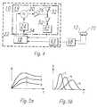
- Fig. 1 is a block circuit diagram of the interrogator unit according tothe invention;
- Figs. 2a-2b are graphs of the responder unit's response transmittedpower vs. frequency wherein the desired frequency is denoted as fo;
- Fig. 3 is a block circuit diagram of the responder unit according to theinvention;
- Fig. 4 is a block diagram of an alternative system block diagram usinga loosely coupled pick-up coil to detect the responder unit's responsetransmitted power; and
- Figs. 5a-5b are graphs illustrating the coupling of power between theresponder unit and interrogator unit for progressively closer matchedresponder unit tuned frequencies.
- Corresponding numerals and symbols in the different figures refer tocorresponding parts unless otherwise indicated.
- Referring now to Fig. 1, the
interrogation unit 10 contains as centralcontrol unit amicroprocessor 18 which is responsible for the control of thefunction sequences. Awireless datacom transceiver 19 under control ofmicroprocessor 18 is responsible for communications with other interrogatorunits having other wireless datacom transceivers and for communicationwith responder units12 (not shown, see Fig. 3). Thewireless datacomtransceiver 19 comprises anRF oscillator 20 which generates RF oscillationsas soon as it has been set in operation by a signal at theoutput 22 of themicroprocessor 18. Further components which are preferably contained within thewireless datacom transceiver 19 include amodulator 24, anoutput amplifier 26, anantenna 33, aninput amplifier 52, and ademodulator 62. Although, preferably, these components are contained intheinterrogator unit 12 it may not be necessary for all the components to beused. For example, in another embodiment of the invention theamplifiers RFoscillator 20 might be constructed to directly radiate into the transmittingmedium without the use aseparate antenna 33. - Still referring to Fig. 1, the oscillations of
RF oscillator 20 may bemodulated by amodulator 24 which is controlled by anoutput 34 of themicroprocessor 18. The output signal of theRF oscillator 20 is supplied byanamplifier 26 to anantenna 33 which transmits the RF interrogation pulsesupplied to it by theoscillator 20 and receives the RF signal sent back by theresponder unit 12. The RF signals received by theantenna 33 are suppliedto anamplifier 52 which amplifies the RF signals. The output of theamplifier 52 is connected to ademodulator 62 which from the signal suppliedthereto generates a demodulated data stream which is supplied to theinput64 of themicroprocessor 18. In a preferred embodiment, thedemodulator circuitry 62 might further provide a radio signal strengthindictor (RSSI) signal which is an analog signal indicating the strength of thereceived signal. RSSI might be received by an analog-to-digital converter(ADC)63 which would make a digital signal indicating the received signalstrength available at theinput 65 ofmicroprocessor 18. The use of thisinformation will be described hereinbelow. - In accordance with the present invention, the
interrogator 12 isfurther operable to measure the strength of a received communication signal,including the effects of coupling efficiency and other filtering of the receivedsignal. One method of doing this is by the RSSI signal discussed above,although many other methods known in the art could be used. Power oramplitude measurements of the incoming signal are both possible ways tomeasure the effective communication signal strength betweenresponder unit 12 andinterrogator unit 10. For example, if theinterrogator 10 is inwireless electrical communication with aresponder unit 12, then theefficiency of this wireless communication should be maximized when theresonant frequency of the responder's transmitting antenna133 (not shown,see Fig. 3) is exactly matched to the resonance of the interrogator's receivingantenna 33. - The importance of this frequency matching is illustrated in Figs. 2a-b.Notice in Fig. 2a that the peak of transmission power of the responder'stransmitting antenna133 is not aligned with the desired frequency f0. Thedesired frequency f0 is normally the resonant frequency of the interrogator'sreceiving
antenna 33. This frequency mismatch results in lowered signalcoupling between the antennas33,133. In the example shown, the powerspectrum intersects with the desired frequency f0 at approximately 50% of itsmaximum, resulting in a great loss of range and/or immunity to interference.The radio signal strength indicator (RSSI) signal will be a measurement ofthe received signal strength as it is coupled between the transmitting andreceivingantennas 133,33 through the transmitting medium. As such, itwill have a maximum which generally occurs when the transmitting andreceivingantennas 133,33 are identically tuned. By using this RSSI signal,as converted byADC 63, theinterrogator unit 10 can tune theresponderunit 12 by sending data to theresponder unit 12 corresponding to a changeor Δ (delta) in frequency. An example protocol for tuning theresponder 12might be to send Δl and Δh data to theresponder unit 12, where Δl has theeffect of tuning theresonant circuit 130 of theresponder unit 12 to a lowerfrequency than is effected by Δh. Theinterrogator unit 10 then monitors theRSSI signal viaADC 63 as theresponder unit 12 responds using both the Δland the Δh data to modify its resonant frequency as will be described below.If the RSSI signal is greater using Δl than using Δh, then in this sampleprotocol one would assume that the responder unit is detuned to a higherthan desired frequency and that by lowering the resonant frequency by Δl thetuning match between transmitter and receiver has been improved. In thisinstance, the resonant frequency would continue to be lowered in Δl increments until the RSSI signal ceases to increase incrementally. At thistime the protocol might assume that a maximum has been reached and thatthe responder unit has been properly tuned. Conversely, if the RSSI signal isgreater using Δh than using Δl, then in this sample protocol one wouldassume that the responder unit is detuned to a lower than desired frequencyand that by increasing the resonant frequency by Δh the tuning matchbetween transmitter and receiver has been improved. In this instance, theresonant frequency would continue to be increased in Δh increments until theRSSI signal ceases to increase incrementally. At this time the protocol mightassume that a maximum has been reached and that the responder unit hasbeen properly tuned. Naturally, many other algorithms exist for finding localextrema, for example, adaptive algorithms might not only record thedirection of the change in the RSSI signal, but also the magnitude. If thechange in magnitude is small then it might be desirable, depending on thecharacteristic shape of the frequency response, to increase the magnitude ofthe Δl or Δh. Many such algorithms are well known in the art and will beapparent to persons skilled in the art upon reference to the description.The procedure of programming aresponder unit 12 with tuning data will nowbe described below in reference to a half-duplex communication protocol.Other methods to program aresponder unit 12 will be apparent to one ofordinary skill in the art upon review of this specification. - The
responder unit 12 illustrated in Fig. 3 contains for reception of theRF interrogation pulse a parallelresonant circuit 130 having a coil132 and acapacitor134. In addition the parallelresonant circuit 130 is connected toanRF bus 138. An RF carrier occurs at theRF bus 138 whenever theparallelresonant circuit 130 receives an RF interrogation pulse from theinterrogator unit 10.Control circuit 118 receives this RF signal and in thepreferred embodiment will respond to the RF interrogation pulse after theinterrogator unit 10 ceases transmitting.Control circuit 118 responds byfurnishing at itsoutput 188 an excitation pulse or pluck signal. Saidexcitation pulse renders the field-effect transistor 190 conductive which inturn applies theRF bus 138 to ground for the duration of the excitationpulse. This provides a direct current from thestorage capacitor 136 throughthe coil132 thus providing energy to the resonant circuit and maintaining acarrier wave oscillation in theresonant circuit 130. - Connected to the
RF bus 138 is acapacitor 198 which by a field-effecttransistor (FET)200 acting as a switch can be operatively connected to theparallelresonant circuit 130. In this manner data can be modulated uponthe carrier wave. Specifically, if theFET 200 is non-conducting or switched"off" then the carrier wave will continue to oscillate at its normal frequency.If, however, theFET 200 is made conductive or switched "on" then thecapacitor 198 will be connected in parallel across the resonant circuit therebyproviding a new resonant frequency which will be lowered by the addedcapacitance. In response to data applied to the gate ofFET 200 the carrierwave is then frequency modulated. - The
control circuit 118 is further operable to demodulate, from the RFcarrier wave of the RF programming sequence, data which may be used tochange or "tune" the frequency with which the RF carrier wave generator orresonant circuit 130 operates. For changing or tuning theresonant circuit 130 frequency, aprogrammable tuning network 238 is provided in thepreferred embodiment of the present invention. Thisprogrammable tuningnetwork 238 operates by switching a network ofparallel capacitors 240, eachcapacitor 240 being connected through a field-effect transistor orFET 242 inparallel with theresonant circuit 130. Each field-effect transistor 242 isconnected to alatch 244 which receives and latches data from thecontrolcircuit 118 viadata bus 220. An EEPROM might replace thelatch 244 tostore the EEPROM resonance tuning function. The contents of the EEPROMcan be changed by thecontrol circuit 118 in response to commands sent bytheinterrogator unit 10. By switching a field-effect transistor 242 to a conducting "ON" state, its associatedcapacitor 240 is connected in parallelwith parallelresonant circuit 130. This added capacitance will lower theresonant frequency of the parallelresonant circuit 130. By switching afield-effect transistor 242 to a non-conducting "OFF" state, its associatedcapacitor 240 is floating and has no effect on the parallelresonantcircuit 130. Anetwork 238 of FET/capacitor pairs240,242 can provide manydifferent values of added capacitances depending on the combinations of eachcapacitor's240 relative value as is well known in the art. Alternatively,latch244 could be a one-time-programmable (OTP) memory such that thedata is fixedly stored therein and the device may be permanentlyprogrammed to set the value ofprogrammable tuning network 238. - For the embodiment described above the
responder unit 12 must be ina fixed position relative to theinterrogator unit 10 in order to havepredictably reliable field strengths to use as the tuning criteria. Thealternative embodiment shown in Fig. 4 does not carry this requirement.This alternative embodiment comprises acoil 70 loosely coupled to theresponder unit 12. Thiscoil 70 preferably is coiled aboutresponder unit 12to detect the RF responses given by theresponder unit 12. The coil connectsto thesignal amplitude detector 68 which decodes the signal amplitude orfield strength of the RF responses and communicates the result as a "ReturnSignal" to theADC 63 which again would make a digital signal indicatingthe received signal strength available formicroprocessor 18. - With reference now to Figs. 5a-5b, graphs are shown for severaldifferent frequencies (a, b, and c) to which the
responder unit 12 is tuned.Fig. 5a shows the "Power Signal" and the "Return Signal" as they vary withtime for instances in which the antenna is tuned to one of the threefrequencies (a, b, or c). The corresponding graph of Fig. 5b gives a frequencyspectrum of the coupling between theinterrogator unit 10 to theresponderunit 12 for the three frequencies as seen by the pick-upcoil 70. Eachprogressively lower frequency is more closely matched to the resonantfrequency of theinterrogator unit 10 causing a much higher and narrower frequency response as shown in Fig. 5b. As a way to determine the couplingstrength between the interrogator andresponder unit interrogatorunit 10 can measure the time in which it takes for the "Power Signal" asmeasured by the pick-up coil to reach a given level. The more quickly the"Power Signal" reaches this given level, the more highly tuned theresponderunit 10 is to theinterrogator unit 10. - Yet another method for retuning or initializing the responder unitafter normal RF-ID interrogation cycles is to measure the strength of RFresponses to consecutive reading cycles. In this case two or moreinterrogations can be executed where the
interrogator unit 10 asks theresponder unit 12 to respond with a lower and a higher tuning capacitortrimming value. Theinterrogator unit 10 then analyzes the response/fieldstrength and continues retuning or confirms the previous status. - Implementation is contemplated in discrete components or fullyintegrated circuits in silicon, gallium arsenide, or other electronic materialsfamilies, as well as in optical-based or other technology-based forms andembodiments. It should be understood that various embodiments of theinvention can employ or be embodied in hardware, software or microcodedfirmware.
- While this invention has been described with reference to illustrativeembodiments, this description is not intended to be construed in a limitingsense. Various modifications and combinations of the illustrativeembodiments, as well as other embodiments of the invention, will beapparent to persons skilled in the art upon reference to the description. Forinstance, in systems using a full duplex or simultaneous power/receiveprotocol, the signal amplitude information can be derived from the modulatedsidebands which are created by the responder from the carrier emitted.
Claims (17)
- A method of communicating between an interrogator unit(10) having a first resonant circuit and a responder unit(12) having a second resonant circuit (130), said methodcomprising the steps of storing energy in a responder unitenergy accumulator (136) in a contactless fashion by RFenergy transmitted from said interrogation unit (10), tosaid responder unit (12), exciting within the resonantcircuit of said responder unit (12) an RF carrier wave,measuring a signal strength of said RF carrier wave, andcharacterized in that said interrogator unit (10) adjuststhe resonant frequency of the resonant circuit of saidresponder unit (12) responsive to said signal strengthmeasurement.
- The method of claim 1, characterized in that, said signalstrength of said RF carrier wave is measured by a pick-upcoil (70) which is loosely coupled to said second resonantcircuit of said responder unit (12).
- The method of claim 1 or 2, characterized in that thestep of transmitting said RF carrier wave is a firstresponse from said responder unit (12) to said interrogatorunit transmission.
- The method of any preceding claim characterized in thatsaid method further comprises said step of performing themeasurement of the signal strength within said interrogatorunit (10).
- The method of claim 4 characterized in that the step ofadjusting the resonant frequency of said one of saidresonant circuits responsive to said signal strengthmeasurement is by transmitting at least one RF programmingsequence from said interrogation unit (10) to said responderunit (12).
- The method of claim 5 characterized in that said methodfurther comprises the step of receiving at said responderunit (12) a first set of data transmitted by said RFprogramming sequence from said interrogator unit (10).
- The method of claim 6 characterized in that said methodof further comprises the step of modifying an internallystored frequency setting within said responder unit (12) inresponse to said first set of data.
- The method of any preceding claim characterized in thatsaid RF carrier wave is generated by a parallel LC oscillator(130) having at least one parallel inductor (132) andat least one parallel capacitor (134).
- The method of claim 8 characterized in that said methodfurther comprises the step of modifying the frequency ofsaid RF carrier wave in accordance with said internallystored frequency setting by selectively changing thecapacitance of said LC oscillator (130).
- The method of claim 9, characterized in that saidcapacitance of said LC oscillator (130) is selectivelychanged by connecting and disconnecting one of at leasttwo parallel capacitors (240).
- The method of any preceding claim characterized in thatsaid method further comprises the step of storing thereceived signal strength subsequent said measuring step.
- The method of claim 6, or any claims 7 - 11 in that theydepend from claim 6, characterized in that said methodfurther comprises the step of sending a second set of datatransmitted by another RF programming sequence from saidinterrogator unit (10).
- The method of claim 12 characterized in that said methodfurther comprises the step of modifying the frequency ofsaid RF carrier wave in accordance with said second set ofdata.
- The method of claim 12 or claim 13 characterized in thatsaid method further comprises the step of transmitting saidRF carrier wave in a second response from said responderunit to said interrogator unit (10).
- The method of claim 14 characterized in that said methodfurther comprises the step of measuring within said interrogatorunit (10) the received signal strength of said RFcarrier wave of said second response.
- The method of claim 16 characterized in that said methodfurther comprises the step of comparing a received signalstrength with said measured signal strength.
- A transponder arrangement characterized in that saidtransponder arrangement comprisesa) an interrogator unit (10) which transmits at leastone RF programming sequence containing tuning data followedby at least one RF interrogation pulse, said interrogatorunit (10) comprising;i) a transmitter which transmits saidinterrogation pulse and said RF programming sequence,ii) a receiver for receiving a wireless responsefrom a responder unit (12),iii) a detection circuit for detecting thestrength of a carrier wave generated by said responder unit,iv) a control circuit (18) for analyzing thedetected strength of said carrier wave and for determiningif a new set of tuning data for another RF programmingsequence needs to be computed; andb) a responder unit (12) which upon receipt of said RFinterrogation pulse transmits read data stored therein backto the interrogator (10) in the form of said wirelessresponse, said responder unit (12) comprisingi) a responder unit reception circuit forreceiving said tuning data transmitted by said RFprogramming sequence from said interrogator unit (10),ii) a memory suitable for having memory datatherein modified by said tuning data received by saidreception circuit,iii) a responder unit energy accumulator (136)which stores energy contained in the RF interrogation pulse,iv) a responder unit RF carrier wave generatorhaving a resonant frequency, andv) a tuning circuit which modifies the resonantfrequency of said RF carrier wave generator in accordancewith said memory data.
Applications Claiming Priority (2)
| Application Number | Priority Date | Filing Date | Title |
|---|---|---|---|
| US07/991,044US5396251A (en) | 1992-12-15 | 1992-12-15 | Electronic transponder tuning procedure |
| US991044 | 1997-12-15 |
Publications (3)
| Publication Number | Publication Date |
|---|---|
| EP0615136A2 EP0615136A2 (en) | 1994-09-14 |
| EP0615136A3 EP0615136A3 (en) | 1995-05-03 |
| EP0615136B1true EP0615136B1 (en) | 1999-03-17 |
Family
ID=25536799
Family Applications (1)
| Application Number | Title | Priority Date | Filing Date |
|---|---|---|---|
| EP93120230AExpired - LifetimeEP0615136B1 (en) | 1992-12-15 | 1993-12-15 | Electronic transponder tuning procedure |
Country Status (3)
| Country | Link |
|---|---|
| US (2) | US5396251A (en) |
| EP (1) | EP0615136B1 (en) |
| DE (1) | DE69323995T2 (en) |
Cited By (8)
| Publication number | Priority date | Publication date | Assignee | Title |
|---|---|---|---|---|
| US8754647B2 (en) | 2009-07-03 | 2014-06-17 | Koninklijke Philips N.V. | Detunable RF reception antenna device |
| US11736959B2 (en) | 2006-11-18 | 2023-08-22 | Rfmicron, Inc. | Radio frequency (RF) field strength detecting circuit |
| US11817637B2 (en) | 2006-11-18 | 2023-11-14 | Rfmicron, Inc. | Radio frequency identification (RFID) moisture tag(s) and sensors with extended sensing via capillaries |
| US11831351B2 (en) | 2006-11-18 | 2023-11-28 | Rfmicron, Inc. | Computing device for processing environmental sensed conditions |
| US12073272B2 (en) | 2006-11-18 | 2024-08-27 | Rfmicron, Inc. | Generating a response by a radio frequency identification (RFID) tag within a field strength shell of interest |
| US12099028B2 (en) | 2014-10-08 | 2024-09-24 | Rfmicron, Inc. | Wireless sensor with multiple sensing options |
| US12132468B2 (en) | 2006-11-18 | 2024-10-29 | Rfmicron, Inc. | Method for sensing environmental conditions |
| US12391076B2 (en) | 2006-11-18 | 2025-08-19 | Rfmicron, Inc. | Pressure based wireless sensor and applications thereof |
Families Citing this family (135)
| Publication number | Priority date | Publication date | Assignee | Title |
|---|---|---|---|---|
| US5396251A (en)* | 1992-12-15 | 1995-03-07 | Texas Instruments Deutschland Gmbh | Electronic transponder tuning procedure |
| JPH085731A (en)* | 1993-10-04 | 1996-01-12 | Texas Instr Deutschland Gmbh | Determination of position of rf -id transponder |
| US5453748A (en)* | 1993-11-15 | 1995-09-26 | Westinghouse Norden Systems | Method and apparatus for responding to an interrogation signal |
| US5621396A (en)* | 1994-06-30 | 1997-04-15 | Texas Instruments Incorporated | Method and apparatus with adaptive transponder plucking |
| US6249212B1 (en)* | 1994-10-05 | 2001-06-19 | Avid Marketing, Inc. | Universal electronic identification tag |
| DE4438286C2 (en)* | 1994-10-26 | 2002-09-12 | Siemens Ag | System for contactless energy and data transmission |
| JPH08307308A (en)* | 1995-01-12 | 1996-11-22 | Texas Instr Deutschland Gmbh | Charging capacitor discharge controller in transponder |
| EP0791706B1 (en)* | 1996-01-31 | 2004-07-14 | Texas Instruments Deutschland Gmbh | Improvements in or relating to full-wave rectifiers |
| US5751114A (en)* | 1996-05-24 | 1998-05-12 | International Business Machines Corporation | Apparatus, method and article of manufacture for carrier frequency compensation in a FM radio transmitter |
| US5761259A (en)* | 1996-05-24 | 1998-06-02 | International Business Machines Corporation | Apparatus, method and article of manufacture for carrier frequency compensation in a FM radio |
| US5734676A (en)* | 1996-05-24 | 1998-03-31 | International Business Machines Corporation | Apparatus, method and article of manufacture for carrier frequency compensation in a FM radio receiver |
| US5847447A (en)* | 1996-07-09 | 1998-12-08 | Ambient Corporation | Capcitively coupled bi-directional data and power transmission system |
| US5742641A (en)* | 1996-07-18 | 1998-04-21 | International Business Machines Corporation | Apparatus, method and article of manufacture for the dynamic compensation of FM deviation in a FM radio receiver |
| US6466131B1 (en)* | 1996-07-30 | 2002-10-15 | Micron Technology, Inc. | Radio frequency data communications device with adjustable receiver sensitivity and method |
| FR2752115B1 (en)* | 1996-07-31 | 1999-01-29 | Inside Technologies | PROGRAMMABLE SWITCH, ADJUSTABLE CAPACITY AND RESONANT CIRCUIT MADE BY SUCH A SWITCH |
| US6084530A (en)* | 1996-12-30 | 2000-07-04 | Lucent Technologies Inc. | Modulated backscatter sensor system |
| US6184841B1 (en) | 1996-12-31 | 2001-02-06 | Lucent Technologies Inc. | Antenna array in an RFID system |
| US6046683A (en)* | 1996-12-31 | 2000-04-04 | Lucent Technologies Inc. | Modulated backscatter location system |
| US6456668B1 (en) | 1996-12-31 | 2002-09-24 | Lucent Technologies Inc. | QPSK modulated backscatter system |
| US6130623A (en)* | 1996-12-31 | 2000-10-10 | Lucent Technologies Inc. | Encryption for modulated backscatter systems |
| EP0898815B1 (en)* | 1997-01-21 | 2005-09-28 | Koninklijke Philips Electronics N.V. | Transponder communications device |
| US6057779A (en)* | 1997-08-14 | 2000-05-02 | Micron Technology, Inc. | Method of controlling access to a movable container and to a compartment of a vehicle, and a secure cargo transportation system |
| US6356535B1 (en)* | 1998-02-04 | 2002-03-12 | Micron Technology, Inc. | Communication systems and methods of communicating |
| DE19809624C1 (en)* | 1998-03-07 | 1999-05-27 | Bosch Gmbh Robert | Electronic disabling device for automobile |
| ES2169612T3 (en)* | 1998-07-21 | 2002-07-01 | Koninkl Philips Electronics Nv | SYSTEM FOR DATA TRANSMISSION FROM A DATA CARRIER TO A STATION THROUGH AT LEAST ANOTHER AUXILIARY CARRIER SIGNAL. |
| US6317027B1 (en) | 1999-01-12 | 2001-11-13 | Randy Watkins | Auto-tunning scanning proximity reader |
| US7571139B1 (en) | 1999-02-19 | 2009-08-04 | Giordano Joseph A | System and method for processing financial transactions |
| US8538801B2 (en) | 1999-02-19 | 2013-09-17 | Exxonmobile Research & Engineering Company | System and method for processing financial transactions |
| US8636648B2 (en) | 1999-03-01 | 2014-01-28 | West View Research, Llc | Endoscopic smart probe |
| US10973397B2 (en) | 1999-03-01 | 2021-04-13 | West View Research, Llc | Computerized information collection and processing apparatus |
| US8065155B1 (en) | 1999-06-10 | 2011-11-22 | Gazdzinski Robert F | Adaptive advertising apparatus and methods |
| US7710273B2 (en)* | 1999-09-02 | 2010-05-04 | Round Rock Research, Llc | Remote communication devices, radio frequency identification devices, wireless communication systems, wireless communication methods, radio frequency identification device communication methods, and methods of forming a remote communication device |
| US7156301B1 (en) | 1999-09-07 | 2007-01-02 | American Express Travel Related Services Company, Inc. | Foldable non-traditionally-sized RF transaction card system and method |
| US7306158B2 (en) | 2001-07-10 | 2007-12-11 | American Express Travel Related Services Company, Inc. | Clear contactless card |
| US7837116B2 (en) | 1999-09-07 | 2010-11-23 | American Express Travel Related Services Company, Inc. | Transaction card |
| US7093767B2 (en)* | 1999-09-07 | 2006-08-22 | American Express Travel Related Services Company, Inc. | System and method for manufacturing a punch-out RFID transaction device |
| US7239226B2 (en) | 2001-07-10 | 2007-07-03 | American Express Travel Related Services Company, Inc. | System and method for payment using radio frequency identification in contact and contactless transactions |
| US7889052B2 (en) | 2001-07-10 | 2011-02-15 | Xatra Fund Mx, Llc | Authorizing payment subsequent to RF transactions |
| US7070112B2 (en)* | 1999-09-07 | 2006-07-04 | American Express Travel Related Services Company, Inc. | Transparent transaction device |
| US8429041B2 (en)* | 2003-05-09 | 2013-04-23 | American Express Travel Related Services Company, Inc. | Systems and methods for managing account information lifecycles |
| US8543423B2 (en) | 2002-07-16 | 2013-09-24 | American Express Travel Related Services Company, Inc. | Method and apparatus for enrolling with multiple transaction environments |
| US7268668B2 (en)* | 2003-05-09 | 2007-09-11 | American Express Travel Related Services Company, Inc. | Systems and methods for managing multiple accounts on a RF transaction instrument |
| US7172112B2 (en)* | 2000-01-21 | 2007-02-06 | American Express Travel Related Services Company, Inc. | Public/private dual card system and method |
| US7627531B2 (en) | 2000-03-07 | 2009-12-01 | American Express Travel Related Services Company, Inc. | System for facilitating a transaction |
| US6369710B1 (en) | 2000-03-27 | 2002-04-09 | Lucent Technologies Inc. | Wireless security system |
| US6806812B1 (en)* | 2000-04-26 | 2004-10-19 | Micron Technology, Inc. | Automated antenna trim for transmitting and receiving semiconductor devices |
| US20030169169A1 (en)* | 2000-08-17 | 2003-09-11 | Luc Wuidart | Antenna generating an electromagnetic field for transponder |
| US6600418B2 (en) | 2000-12-12 | 2003-07-29 | 3M Innovative Properties Company | Object tracking and management system and method using radio-frequency identification tags |
| US7542942B2 (en) | 2001-07-10 | 2009-06-02 | American Express Travel Related Services Company, Inc. | System and method for securing sensitive information during completion of a transaction |
| US7650314B1 (en) | 2001-05-25 | 2010-01-19 | American Express Travel Related Services Company, Inc. | System and method for securing a recurrent billing transaction |
| US7725427B2 (en)* | 2001-05-25 | 2010-05-25 | Fred Bishop | Recurrent billing maintenance with radio frequency payment devices |
| US7121471B2 (en)* | 2001-07-10 | 2006-10-17 | American Express Travel Related Services Company, Inc. | Method and system for DNA recognition biometrics on a fob |
| US7059531B2 (en)* | 2001-07-10 | 2006-06-13 | American Express Travel Related Services Company, Inc. | Method and system for smellprint recognition biometrics on a fob |
| US7762457B2 (en)* | 2001-07-10 | 2010-07-27 | American Express Travel Related Services Company, Inc. | System and method for dynamic fob synchronization and personalization |
| US7827106B2 (en)* | 2001-07-10 | 2010-11-02 | American Express Travel Related Services Company, Inc. | System and method for manufacturing a punch-out RFID transaction device |
| US8294552B2 (en) | 2001-07-10 | 2012-10-23 | Xatra Fund Mx, Llc | Facial scan biometrics on a payment device |
| US20050116810A1 (en)* | 2001-07-10 | 2005-06-02 | American Express Travel Related Services Company, Inc. | Method and system for vascular pattern recognition biometrics on a fob |
| US20040239481A1 (en)* | 2001-07-10 | 2004-12-02 | American Express Travel Related Services Company, Inc. | Method and system for facial recognition biometrics on a fob |
| US7996324B2 (en) | 2001-07-10 | 2011-08-09 | American Express Travel Related Services Company, Inc. | Systems and methods for managing multiple accounts on a RF transaction device using secondary identification indicia |
| US7312707B1 (en) | 2001-07-10 | 2007-12-25 | American Express Travel Related Services Company, Inc. | System and method for authenticating a RF transaction using a transaction account routing number |
| US7746215B1 (en) | 2001-07-10 | 2010-06-29 | Fred Bishop | RF transactions using a wireless reader grid |
| US7429927B2 (en) | 2001-07-10 | 2008-09-30 | American Express Travel Related Services Company, Inc. | System and method for providing and RFID transaction device |
| US7154375B2 (en)* | 2001-07-10 | 2006-12-26 | American Express Travel Related Services Company, Inc. | Biometric safeguard method with a fob |
| US8279042B2 (en) | 2001-07-10 | 2012-10-02 | Xatra Fund Mx, Llc | Iris scan biometrics on a payment device |
| US7493288B2 (en) | 2001-07-10 | 2009-02-17 | Xatra Fund Mx, Llc | RF payment via a mobile device |
| US20040236700A1 (en)* | 2001-07-10 | 2004-11-25 | American Express Travel Related Services Company, Inc. | Method and system for keystroke scan recognition biometrics on a fob |
| US20050160003A1 (en)* | 2001-07-10 | 2005-07-21 | American Express Travel Related Services Company, Inc. | System and method for incenting rfid transaction device usage at a merchant location |
| US7503480B2 (en) | 2001-07-10 | 2009-03-17 | American Express Travel Related Services Company, Inc. | Method and system for tracking user performance |
| US7705732B2 (en) | 2001-07-10 | 2010-04-27 | Fred Bishop | Authenticating an RF transaction using a transaction counter |
| US7303120B2 (en)* | 2001-07-10 | 2007-12-04 | American Express Travel Related Services Company, Inc. | System for biometric security using a FOB |
| US8538863B1 (en) | 2001-07-10 | 2013-09-17 | American Express Travel Related Services Company, Inc. | System and method for facilitating a transaction using a revolving use account associated with a primary account |
| US20040233037A1 (en)* | 2001-07-10 | 2004-11-25 | American Express Travel Related Services Company, Inc. | Method and system for iris scan recognition biometrics on a fob |
| US9031880B2 (en) | 2001-07-10 | 2015-05-12 | Iii Holdings 1, Llc | Systems and methods for non-traditional payment using biometric data |
| US9024719B1 (en) | 2001-07-10 | 2015-05-05 | Xatra Fund Mx, Llc | RF transaction system and method for storing user personal data |
| US20040232224A1 (en)* | 2001-07-10 | 2004-11-25 | American Express Travel Related Services Company, Inc. | Method for registering biometric for use with a fob |
| US20040232221A1 (en)* | 2001-07-10 | 2004-11-25 | American Express Travel Related Services Company, Inc. | Method and system for voice recognition biometrics on a fob |
| US7119659B2 (en) | 2001-07-10 | 2006-10-10 | American Express Travel Related Services Company, Inc. | Systems and methods for providing a RF transaction device for use in a private label transaction |
| US8635131B1 (en) | 2001-07-10 | 2014-01-21 | American Express Travel Related Services Company, Inc. | System and method for managing a transaction protocol |
| US7249112B2 (en) | 2002-07-09 | 2007-07-24 | American Express Travel Related Services Company, Inc. | System and method for assigning a funding source for a radio frequency identification device |
| US20040257197A1 (en)* | 2001-07-10 | 2004-12-23 | American Express Travel Related Services Company, Inc. | Method for biometric security using a transponder-reader |
| US7228155B2 (en)* | 2001-07-10 | 2007-06-05 | American Express Travel Related Services Company, Inc. | System and method for remotely initializing a RF transaction |
| US7543738B1 (en) | 2001-07-10 | 2009-06-09 | American Express Travel Related Services Company, Inc. | System and method for secure transactions manageable by a transaction account provider |
| US8960535B2 (en) | 2001-07-10 | 2015-02-24 | Iii Holdings 1, Llc | Method and system for resource management and evaluation |
| US20050033687A1 (en)* | 2001-07-10 | 2005-02-10 | American Express Travel Related Services Company, Inc. | Method and system for auditory emissions recognition biometrics on a fob |
| US9454752B2 (en) | 2001-07-10 | 2016-09-27 | Chartoleaux Kg Limited Liability Company | Reload protocol at a transaction processing entity |
| US7805378B2 (en)* | 2001-07-10 | 2010-09-28 | American Express Travel Related Servicex Company, Inc. | System and method for encoding information in magnetic stripe format for use in radio frequency identification transactions |
| US20040239480A1 (en)* | 2001-07-10 | 2004-12-02 | American Express Travel Related Services Company, Inc. | Method for biometric security using a transponder |
| US20040233039A1 (en)* | 2001-07-10 | 2004-11-25 | American Express Travel Related Services Company, Inc. | System for registering a biometric for use with a transponder |
| US20040233038A1 (en)* | 2001-07-10 | 2004-11-25 | American Express Travel Related Services Company, Inc. | Method and system for retinal scan recognition biometrics on a fob |
| US7668750B2 (en) | 2001-07-10 | 2010-02-23 | David S Bonalle | Securing RF transactions using a transactions counter |
| US7360689B2 (en) | 2001-07-10 | 2008-04-22 | American Express Travel Related Services Company, Inc. | Method and system for proffering multiple biometrics for use with a FOB |
| US7925535B2 (en)* | 2001-07-10 | 2011-04-12 | American Express Travel Related Services Company, Inc. | System and method for securing RF transactions using a radio frequency identification device including a random number generator |
| US20040236699A1 (en) | 2001-07-10 | 2004-11-25 | American Express Travel Related Services Company, Inc. | Method and system for hand geometry recognition biometrics on a fob |
| US8548927B2 (en)* | 2001-07-10 | 2013-10-01 | Xatra Fund Mx, Llc | Biometric registration for facilitating an RF transaction |
| US8001054B1 (en) | 2001-07-10 | 2011-08-16 | American Express Travel Related Services Company, Inc. | System and method for generating an unpredictable number using a seeded algorithm |
| US20040238621A1 (en)* | 2001-07-10 | 2004-12-02 | American Express Travel Related Services Company, Inc. | Method and system for fingerprint biometrics on a fob |
| US20040232222A1 (en)* | 2001-07-10 | 2004-11-25 | American Express Travel Related Services Company, Inc. | Method and system for signature recognition biometrics on a fob |
| US7463133B2 (en)* | 2001-07-10 | 2008-12-09 | American Express Travel Related Services Company, Inc. | Systems and methods for providing a RF transaction device operable to store multiple distinct calling card accounts |
| US6669089B2 (en) | 2001-11-12 | 2003-12-30 | 3M Innovative Properties Co | Radio frequency identification systems for asset tracking |
| US7587756B2 (en)* | 2002-07-09 | 2009-09-08 | American Express Travel Related Services Company, Inc. | Methods and apparatus for a secure proximity integrated circuit card transactions |
| US6805287B2 (en) | 2002-09-12 | 2004-10-19 | American Express Travel Related Services Company, Inc. | System and method for converting a stored value card to a credit card |
| US7095326B2 (en)* | 2003-05-07 | 2006-08-22 | Science Applications International Corporation | Characterizing a cargo container |
| US7268667B2 (en)* | 2003-05-09 | 2007-09-11 | American Express Travel Related Services Company, Inc. | Systems and methods for providing a RF transaction device operable to store multiple distinct accounts |
| JP2007504537A (en)* | 2003-08-29 | 2007-03-01 | シンボル テクノロジーズ インコーポレイテッド | RFID system with selectable backscatter parameters |
| EP1538557B1 (en)* | 2003-12-05 | 2013-02-13 | STMicroelectronics S.A. | Resistive and capacitive modulation in an electromagnetic transponder |
| US7427024B1 (en) | 2003-12-17 | 2008-09-23 | Gazdzinski Mark J | Chattel management apparatus and methods |
| US7183926B2 (en)* | 2004-04-13 | 2007-02-27 | Impinj, Inc. | Adaptable bandwidth RFID tags |
| US7501953B2 (en)* | 2004-04-13 | 2009-03-10 | Impinj Inc | RFID readers transmitting preambles denoting communication parameters and RFID tags interpreting the same and methods |
| US7917088B2 (en) | 2004-04-13 | 2011-03-29 | Impinj, Inc. | Adaptable detection threshold for RFID tags and chips |
| US7973643B2 (en)* | 2004-04-13 | 2011-07-05 | Impinj, Inc. | RFID readers transmitting preambles denoting data rate and methods |
| US7314165B2 (en) | 2004-07-01 | 2008-01-01 | American Express Travel Related Services Company, Inc. | Method and system for smellprint recognition biometrics on a smartcard |
| US7318550B2 (en) | 2004-07-01 | 2008-01-15 | American Express Travel Related Services Company, Inc. | Biometric safeguard method for use with a smartcard |
| DE102004037637A1 (en) | 2004-08-02 | 2006-03-16 | Deutsche Thomson-Brandt Gmbh | Receiver circuit and control method |
| DE102004039401A1 (en)* | 2004-08-13 | 2006-03-09 | Siemens Ag | Transceiver transponder system |
| US8049594B1 (en) | 2004-11-30 | 2011-11-01 | Xatra Fund Mx, Llc | Enhanced RFID instrument security |
| US20080211621A1 (en)* | 2005-05-23 | 2008-09-04 | Nxp B.V. | Electronic Communication System, in Particular Authentication Control System, as Well as Corresponding Method |
| US20070279188A1 (en)* | 2006-05-18 | 2007-12-06 | Michelin Recherche Et Technique S.A. | System and method for interrogating a saw via direct physical connection |
| US10224902B2 (en)* | 2006-11-18 | 2019-03-05 | Rfmicron, Inc. | Roll-to-roll production of RFID tags |
| US7791453B2 (en)* | 2006-11-21 | 2010-09-07 | International Business Machines Corporation | System and method for varying response amplitude of radio transponders |
| US20090015407A1 (en)* | 2007-07-13 | 2009-01-15 | Micron Technology, Inc. | Rifid tags and methods of designing rfid tags |
| US7777630B2 (en)* | 2007-07-26 | 2010-08-17 | Round Rock Research, Llc | Methods and systems of RFID tags using RFID circuits and antennas having unmatched frequency ranges |
| JP5023965B2 (en)* | 2007-10-26 | 2012-09-12 | ソニー株式会社 | Reader / writer device and non-contact data carrier system |
| US8855554B2 (en) | 2008-03-05 | 2014-10-07 | Qualcomm Incorporated | Packaging and details of a wireless power device |
| EP2277252A4 (en) | 2008-04-21 | 2017-04-26 | Qualcomm Incorporated | Short range efficient wireless power transfer |
| US8179232B2 (en)* | 2008-05-05 | 2012-05-15 | Round Rock Research, Llc | RFID interrogator with adjustable signal characteristics |
| US7852221B2 (en)* | 2008-05-08 | 2010-12-14 | Round Rock Research, Llc | RFID devices using RFID circuits and antennas having unmatched frequency ranges |
| US8712334B2 (en) | 2008-05-20 | 2014-04-29 | Micron Technology, Inc. | RFID device using single antenna for multiple resonant frequency ranges |
| US8497658B2 (en) | 2009-01-22 | 2013-07-30 | Qualcomm Incorporated | Adaptive power control for wireless charging of devices |
| DE102010055696A1 (en) | 2010-12-22 | 2012-06-28 | Airbus Operations Gmbh | A system for contactless energy transfer, use of a system for contactless energy transfer and vehicle with a system for contactless energy transfer between a first vehicle part and a second vehicle part |
| GB2498346B (en)* | 2012-01-10 | 2016-01-06 | Pet Mate Ltd | Pet door systems and methods of operation thereof |
| US8766712B2 (en) | 2012-05-04 | 2014-07-01 | Analog Devices, Inc. | Quality factor tuning for LC circuits |
| US8918070B2 (en)* | 2012-05-04 | 2014-12-23 | Analog Devices, Inc. | Frequency tuning for LC circuits |
| US9031689B1 (en) | 2012-07-13 | 2015-05-12 | The United States Of America As Represented By The Administrator Of The National Aeronautics And Space Administration | Systems and methods for RFID-enabled dispenser |
| JP2015226196A (en)* | 2014-05-28 | 2015-12-14 | 竹中エンジニアリング株式会社 | Photodetection circuit of light beam type detector |
| US10637444B1 (en)* | 2018-12-21 | 2020-04-28 | Northrop Gruman Systems Corporation | Near field RFID probe with tunning |
Family Cites Families (16)
| Publication number | Priority date | Publication date | Assignee | Title |
|---|---|---|---|---|
| GB1577920A (en)* | 1976-11-01 | 1980-10-29 | Nedap Nv | Detection plate for identification systems |
| US5164732A (en)* | 1980-02-13 | 1992-11-17 | Eid Electronic Identification Systems Ltd. | Highway vehicle identification system with high gain antenna |
| ZA81888B (en)* | 1980-02-13 | 1982-03-31 | Sensory Systems Lab | Electronic identification system |
| US4480178A (en)* | 1983-04-04 | 1984-10-30 | At&T Information Systems | Tuning arrangement for interfacing credit card-like device to a reader system |
| US4912471A (en)* | 1983-11-03 | 1990-03-27 | Mitron Systems Corporation | Interrogator-responder communication system |
| US4724427A (en)* | 1986-07-18 | 1988-02-09 | B. I. Incorporated | Transponder device |
| DE3788348T2 (en)* | 1987-07-31 | 1994-03-17 | Texas Instruments Deutschland | Transponder arrangement. |
| US5287113A (en)* | 1990-02-12 | 1994-02-15 | Texas Instruments Deutschland Gmbh | Voltage limiting batteryless transponder circuit |
| US5025492A (en)* | 1990-04-11 | 1991-06-18 | Texas Instruments Deutschland Gmbh | Damping circuit for the antenna resonance circuit of a radio transmitter-receiver |
| US5114732A (en)* | 1991-04-02 | 1992-05-19 | Kraft General Foods, Inc. | Method of mixing viscous emulsions |
| US5270717A (en)* | 1992-03-26 | 1993-12-14 | Texas Instruments Deutschland Gmbh | Extended range RF-ID transponder |
| US5294931A (en)* | 1992-04-29 | 1994-03-15 | Texas Instruments Deutschland Gmbh | Method of interrogating a plurality of transponders arranged in the transmission range of an interrogating device and transponders for use in the said method |
| US5410315A (en)* | 1992-12-08 | 1995-04-25 | Texas Instruments Incorporated | Group-addressable transponder arrangement |
| US5396251A (en)* | 1992-12-15 | 1995-03-07 | Texas Instruments Deutschland Gmbh | Electronic transponder tuning procedure |
| US5287112A (en)* | 1993-04-14 | 1994-02-15 | Texas Instruments Incorporated | High speed read/write AVI system |
| US5430447A (en)* | 1993-08-23 | 1995-07-04 | Texas Instruments Deutschland Gmbh | Protection against manipulation of batteryless read/write transponders |
- 1992
- 1992-12-15USUS07/991,044patent/US5396251A/ennot_activeExpired - Lifetime
- 1993
- 1993-12-15EPEP93120230Apatent/EP0615136B1/ennot_activeExpired - Lifetime
- 1993-12-15DEDE69323995Tpatent/DE69323995T2/ennot_activeExpired - Lifetime
- 1994
- 1994-12-22USUS08/362,368patent/US5491484A/ennot_activeExpired - Lifetime
Cited By (8)
| Publication number | Priority date | Publication date | Assignee | Title |
|---|---|---|---|---|
| US11736959B2 (en) | 2006-11-18 | 2023-08-22 | Rfmicron, Inc. | Radio frequency (RF) field strength detecting circuit |
| US11817637B2 (en) | 2006-11-18 | 2023-11-14 | Rfmicron, Inc. | Radio frequency identification (RFID) moisture tag(s) and sensors with extended sensing via capillaries |
| US11831351B2 (en) | 2006-11-18 | 2023-11-28 | Rfmicron, Inc. | Computing device for processing environmental sensed conditions |
| US12073272B2 (en) | 2006-11-18 | 2024-08-27 | Rfmicron, Inc. | Generating a response by a radio frequency identification (RFID) tag within a field strength shell of interest |
| US12132468B2 (en) | 2006-11-18 | 2024-10-29 | Rfmicron, Inc. | Method for sensing environmental conditions |
| US12391076B2 (en) | 2006-11-18 | 2025-08-19 | Rfmicron, Inc. | Pressure based wireless sensor and applications thereof |
| US8754647B2 (en) | 2009-07-03 | 2014-06-17 | Koninklijke Philips N.V. | Detunable RF reception antenna device |
| US12099028B2 (en) | 2014-10-08 | 2024-09-24 | Rfmicron, Inc. | Wireless sensor with multiple sensing options |
Also Published As
| Publication number | Publication date |
|---|---|
| EP0615136A3 (en) | 1995-05-03 |
| EP0615136A2 (en) | 1994-09-14 |
| DE69323995T2 (en) | 1999-09-30 |
| DE69323995D1 (en) | 1999-04-22 |
| US5396251A (en) | 1995-03-07 |
| US5491484A (en) | 1996-02-13 |
Similar Documents
| Publication | Publication Date | Title |
|---|---|---|
| EP0615136B1 (en) | Electronic transponder tuning procedure | |
| EP0663724B1 (en) | Method of automatic antenna tuning and of demodulation of a FSK modulated signal, respectively | |
| KR100226117B1 (en) | Proximity detecting apparatus | |
| EP1927072B1 (en) | Radio frequency identification device systems | |
| US6650226B1 (en) | Detection, by an electromagnetic transponder reader, of the distance separating it from a transponder | |
| US6130612A (en) | Antenna for RF tag with a magnetoelastic resonant core | |
| US6473028B1 (en) | Detection of the distance between an electromagnetic transponder and a terminal | |
| US5703573A (en) | Transmitter-receiver for non-contact IC card system | |
| EP0657836B1 (en) | Extended range RF-ID transponder | |
| EP3484059B1 (en) | Improved device detection in contactless communication systems | |
| US6282407B1 (en) | Active electrostatic transceiver and communicating system | |
| US6028503A (en) | Contactless data transmission and receiving device with a synchronous demodulator | |
| US5774062A (en) | Tag responsive to high-frequecy for varying capacitance of tuning capacitor | |
| US6021951A (en) | Wireless IC card and IC card reader communication system | |
| US6639514B1 (en) | Method for selecting and writing into RFID-transponders | |
| US5866891A (en) | Transmitter-receiver for non-contact IC card system | |
| EP0537378B1 (en) | Method of reading the data stored in a passive responder by means of an interrogation device comprising a receiving section | |
| EP2330538A1 (en) | Radio frequency transponder | |
| CN113283259B (en) | RFID-based multi-tag radio frequency identification system and method | |
| EP0492569B1 (en) | A system and method for the non-contact transmission of data | |
| EP1168237B1 (en) | Broad bandwidth, high impedance transponder for electronic identification system | |
| US6879246B2 (en) | Evaluation of the number of electromagnetic transponders in the field of a reader | |
| US6911876B2 (en) | Communication terminal for transceiving two frequencies using a common one turn antenna | |
| US6674365B2 (en) | Communication terminal | |
| WO2024178568A1 (en) | System and method of antenna calibration for an nfc tag |
Legal Events
| Date | Code | Title | Description |
|---|---|---|---|
| PUAI | Public reference made under article 153(3) epc to a published international application that has entered the european phase | Free format text:ORIGINAL CODE: 0009012 | |
| AK | Designated contracting states | Kind code of ref document:A2 Designated state(s):DE FR GB IT NL | |
| PUAL | Search report despatched | Free format text:ORIGINAL CODE: 0009013 | |
| AK | Designated contracting states | Kind code of ref document:A3 Designated state(s):DE FR GB IT NL | |
| 17P | Request for examination filed | Effective date:19951102 | |
| 17Q | First examination report despatched | Effective date:19970502 | |
| GRAG | Despatch of communication of intention to grant | Free format text:ORIGINAL CODE: EPIDOS AGRA | |
| GRAG | Despatch of communication of intention to grant | Free format text:ORIGINAL CODE: EPIDOS AGRA | |
| GRAG | Despatch of communication of intention to grant | Free format text:ORIGINAL CODE: EPIDOS AGRA | |
| GRAH | Despatch of communication of intention to grant a patent | Free format text:ORIGINAL CODE: EPIDOS IGRA | |
| GRAH | Despatch of communication of intention to grant a patent | Free format text:ORIGINAL CODE: EPIDOS IGRA | |
| GRAA | (expected) grant | Free format text:ORIGINAL CODE: 0009210 | |
| ITF | It: translation for a ep patent filed | ||
| AK | Designated contracting states | Kind code of ref document:B1 Designated state(s):DE FR GB IT NL | |
| REF | Corresponds to: | Ref document number:69323995 Country of ref document:DE Date of ref document:19990422 | |
| ET | Fr: translation filed | ||
| PLBE | No opposition filed within time limit | Free format text:ORIGINAL CODE: 0009261 | |
| STAA | Information on the status of an ep patent application or granted ep patent | Free format text:STATUS: NO OPPOSITION FILED WITHIN TIME LIMIT | |
| 26N | No opposition filed | ||
| REG | Reference to a national code | Ref country code:GB Ref legal event code:IF02 | |
| PGFP | Annual fee paid to national office [announced via postgrant information from national office to epo] | Ref country code:IT Payment date:20061231 Year of fee payment:14 | |
| PG25 | Lapsed in a contracting state [announced via postgrant information from national office to epo] | Ref country code:IT Free format text:LAPSE BECAUSE OF NON-PAYMENT OF DUE FEES Effective date:20071215 | |
| PGFP | Annual fee paid to national office [announced via postgrant information from national office to epo] | Ref country code:FR Payment date:20100222 Year of fee payment:17 | |
| PGFP | Annual fee paid to national office [announced via postgrant information from national office to epo] | Ref country code:GB Payment date:20100208 Year of fee payment:17 | |
| PGFP | Annual fee paid to national office [announced via postgrant information from national office to epo] | Ref country code:NL Payment date:20100618 Year of fee payment:17 | |
| REG | Reference to a national code | Ref country code:NL Ref legal event code:V1 Effective date:20110701 | |
| GBPC | Gb: european patent ceased through non-payment of renewal fee | Effective date:20101215 | |
| REG | Reference to a national code | Ref country code:FR Ref legal event code:ST Effective date:20110831 | |
| PG25 | Lapsed in a contracting state [announced via postgrant information from national office to epo] | Ref country code:FR Free format text:LAPSE BECAUSE OF NON-PAYMENT OF DUE FEES Effective date:20110103 | |
| PG25 | Lapsed in a contracting state [announced via postgrant information from national office to epo] | Ref country code:GB Free format text:LAPSE BECAUSE OF NON-PAYMENT OF DUE FEES Effective date:20101215 | |
| PG25 | Lapsed in a contracting state [announced via postgrant information from national office to epo] | Ref country code:NL Free format text:LAPSE BECAUSE OF NON-PAYMENT OF DUE FEES Effective date:20110701 | |
| PGFP | Annual fee paid to national office [announced via postgrant information from national office to epo] | Ref country code:DE Payment date:20111230 Year of fee payment:19 | |
| PG25 | Lapsed in a contracting state [announced via postgrant information from national office to epo] | Ref country code:DE Free format text:LAPSE BECAUSE OF NON-PAYMENT OF DUE FEES Effective date:20130702 | |
| REG | Reference to a national code | Ref country code:DE Ref legal event code:R119 Ref document number:69323995 Country of ref document:DE Effective date:20130702 |