EP0612374B1 - Fuel injection nozzle with additive injection for diesel engines - Google Patents
Fuel injection nozzle with additive injection for diesel enginesDownload PDFInfo
- Publication number
- EP0612374B1 EP0612374B1EP93918898AEP93918898AEP0612374B1EP 0612374 B1EP0612374 B1EP 0612374B1EP 93918898 AEP93918898 AEP 93918898AEP 93918898 AEP93918898 AEP 93918898AEP 0612374 B1EP0612374 B1EP 0612374B1
- Authority
- EP
- European Patent Office
- Prior art keywords
- additive
- space
- fuel
- interspace
- injection
- Prior art date
- Legal status (The legal status is an assumption and is not a legal conclusion. Google has not performed a legal analysis and makes no representation as to the accuracy of the status listed.)
- Expired - Lifetime
Links
Images


Classifications
- F—MECHANICAL ENGINEERING; LIGHTING; HEATING; WEAPONS; BLASTING
- F02—COMBUSTION ENGINES; HOT-GAS OR COMBUSTION-PRODUCT ENGINE PLANTS
- F02M—SUPPLYING COMBUSTION ENGINES IN GENERAL WITH COMBUSTIBLE MIXTURES OR CONSTITUENTS THEREOF
- F02M43/00—Fuel-injection apparatus operating simultaneously on two or more fuels, or on a liquid fuel and another liquid, e.g. the other liquid being an anti-knock additive
- F02M43/04—Injectors peculiar thereto
- F—MECHANICAL ENGINEERING; LIGHTING; HEATING; WEAPONS; BLASTING
- F02—COMBUSTION ENGINES; HOT-GAS OR COMBUSTION-PRODUCT ENGINE PLANTS
- F02M—SUPPLYING COMBUSTION ENGINES IN GENERAL WITH COMBUSTIBLE MIXTURES OR CONSTITUENTS THEREOF
- F02M25/00—Engine-pertinent apparatus for adding non-fuel substances or small quantities of secondary fuel to combustion-air, main fuel or fuel-air mixture
- F—MECHANICAL ENGINEERING; LIGHTING; HEATING; WEAPONS; BLASTING
- F02—COMBUSTION ENGINES; HOT-GAS OR COMBUSTION-PRODUCT ENGINE PLANTS
- F02B—INTERNAL-COMBUSTION PISTON ENGINES; COMBUSTION ENGINES IN GENERAL
- F02B3/00—Engines characterised by air compression and subsequent fuel addition
- F02B3/06—Engines characterised by air compression and subsequent fuel addition with compression ignition
Definitions
- the inventionrelates to a fuel injector Additive injection for diesel engines according to the preamble of the claim 1.
- the fuelin two separate periods and in between that Inject additive, for example water, into the combustion chamber.
- the known for performing this methodhas an injector Antechamber for dividing the pre-injection quantity and a pressure chamber, in the the inlet channel for the fuel and the inlet channel for the Additive open ( Figure 4), or an annular channel that the additive inlet bore connects to the fuel inlet bore ( Figure 3).
- an amount of additiveis added to the pressure chamber or pressed into the inlet bore and temporarily stored there.
- the intermediate amount of additiveis then of the high-pressure fuel after displacement and injecting the pre-injection quantity into the combustion chamber before the injection of the main amount of fuel injected.
- the fuel injector according to the invention with the Features of claim 1has the advantage that the required Additive quantity stored in the correct stratification with every work cycle and is injected. Furthermore, their structure and operation very easy.
- the measures specified in the subclaimsare advantageous Developments of the injection nozzles specified in claim 1 possible.
- the training according to claim 2enables targeted supply and concentrated intermediate storage of the additive in the space.
- a simple manufacture of the vestibule and the Gapis given by the training according to claim 4.
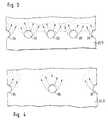
- FIG. 1An embodiment of the invention is shown in the drawing and is described in more detail below. It shows the figure 1 the combustion chamber side half of an injection nozzle in axial section, Figure 2 shows the part of the nozzle body and the valve needle on the combustion chamber side the injection nozzle of Figure 1 in axial section in an enlarged Scale and Figures 3 and 4 a development of part of the nozzle needle 1 and 2 in the area of the mouth of the inlet channel.
- a nozzle body 1is interposed with a union nut 2 an intermediate disk 3 on a nozzle holder 4 (only partially shown) clamped in a spring 5 in a closing spring 6 is arranged.
- a valve needle 11is displaceable, which near the end of the combustion chamber has a closing cone 12, upstream thereof a pressure shoulder 13 and then a guide section 14, and from the closing spring 6 via a pressure pin 15 and a pressure pin 16 with the locking cone 12 against a conical Valve seat 17 at the combustion chamber end of the nozzle body 1 is pressed.
- a throttle bore 18follows the combustion chamber a throttle pin 19 passes through the valve needle 11.
- the pressure shoulder 13 of the nozzle needle 11is from an annular pressure chamber 21 surrounded in the nozzle body 1, in which the inlet bore 7 for the Main fuel flows out. Downstream of the pressure chamber 21 closes Valve seat 17 towards an extension section 22 of the longitudinal bore 9 and thereupon a conical bore 23, of which the throttle bore 18 closer Section forms the valve seat 17.
- valve needle 11Upstream of the closing cone 12 interacting with the valve seat 17 the valve needle 11 is arranged a preliminary storage or antechamber 25, that of an annular recess 24 in the conical nozzle needle formed tip and delimited radially outside by the tapered bore 23 is. Between the antechamber 25 and the pressure chamber 21 is a Space 26 is provided, the radially inside of a constriction 27 in the valve needle 11 and outside of the extension section 22 the longitudinal bore 9 of the nozzle body 1 is limited. In the closed position the valve needle 11 is the space 26 to Pressure chamber 21 connected via an annular throttle gap 28, the from the end part 29 of the extension section close to the pressure chamber 21 22 and of the part 30 of the constriction 27 of the Shank of the valve needle 11 is limited.
- Throttle gap 31the space 26 with the vestibule 25, the Throttle gap 31 on the one hand from the transition 32 of the extension section 22 in the tapered bore 23 and on the other hand by a collar 33 between the constriction 27 and the recess 24 in the valve needle 11 is formed.
- the two throttle gaps 28 and 31are in the only effective in the closed position of the valve needle 11. At the Lifting the valve needle 11 from the valve seat 17 move the surfaces forming the choke gaps 28 and 31 relative to one another, the throttling effect between the individual rooms 21, 26 and 25 is increasingly picking up.
- a plurality, preferably four, radial bores 35which are axial Blind bore 36 in the stem 20 of the valve needle 11 go out.
- the axial Bore 36is about transverse bores 37 with a recess 38 in Nozzle body 1 in connection, in which the inlet channel 8 opens.
- in the Inlet channel 8blocks a check valve 39 the backflow of Additive.
- the first inlet channel 7is via a pressure line 41 and a relief valve 42 with an injection pump 43 for the main fuel, for example diesel oil, and the second inlet channel 8 through an inlet line 44 with a low pressure pump 45 for the Additive, for example water.
- the described injectorworks as follows: After each injection phase, when the valve needle 11 is again in the closed position, the pressure chamber 21, the intermediate space 26 and the antechamber 25 are filled with main fuel. The pre-injection quantity is thus determined by the volume of the antechamber 25, which is adapted to the combustion requirements of the respective engine. In each case between two injection phases, a small predetermined amount of liquid additive is measured by the low-pressure pump 45 and conveyed through the inlet channel 8, the axial bore 36 and the radial bores 35 into the intermediate space 26. The inflowing amount of additive displaces the main fuel remaining there from the previous injection phase against the direction of flow into the pressure chamber 21.
- the throttle gap 31supports the separate remaining of a fuel storage quantity, which is necessary as an ignition quantity, in the antechamber 25 and the throttle gap 28 favors extensive distribution of the metered amount of additive (FIG. 2).
- the main fuelis forced back by the relief valve 42.
- the throttle gap 28also acts on the resulting compression flow by first of all a better distribution of the main fuel in the pressure chamber 21 before the opening pressure is reached.
- FIGS. 3 and 4show, by arranging one more or a smaller number of radial bores opening into the pressure chamber 26 35, the distance between the individual radial bores 35 is influenced by each other, through which the additive in the space 26 flows, a completely closed intermediate layer made of additives be formed (Figure 3), or it can also be isolated Small amounts can be stored in the main fuel ( Figure 4). in the in the latter case, a mixture of additive is formed in the intermediate space 26 and fuel that mixes intensively when injected. Each one or the other configuration is selected as required by the engine.
- the inventionis based on a so-called throttle pin injection nozzle explained in which a pin on the valve needle in the spray hole protrudes. It can also be used with so-called perforated nozzles which spray jets are formed in spray holes with a small cross-section will.
Landscapes
- Engineering & Computer Science (AREA)
- Chemical & Material Sciences (AREA)
- Combustion & Propulsion (AREA)
- Mechanical Engineering (AREA)
- General Engineering & Computer Science (AREA)
- Fuel-Injection Apparatus (AREA)
Abstract
Description
Translated fromGermanDie Erfindung bezieht sich auf eine Kraftstoff-Einspritzdüse mitAdditiveinspritzung für Dieselmotoren nach dem Oberbegriff des Anspruchs1. Um den Verbrennungsverlauf bei Dieselmotoren so zu beeinflussen,daß die Gangruhe erhöht und die Emmission von Stickoxidenvermindert wird, ist es aus der DE 925 139 C bekannt, den Kraftstoffin zwei zeitlich getrennten Zeiträumen und dazwischen dasAdditiv, beispielsweise Wasser, in den Brennraum einzuspritzen. Diezum Durchführen dieses Verfahrens bekannte Einspritzdüse hat einenVorraum zum Abteilen der Voreinspritzmenge und einen Druckraum, inden der Zulaufkanal für den Kraftstoff und der Zulaufkanal für dasAdditiv münden (Figur 4), bzw. einen Ringkanal, der die Additiv-Zulaufbohrungmit der Kraftstoff-Zulaufbohrung verbindet (Figur 3).Während der Einspritzpause wird eine Additivmenge in die Druckkammerbzw. in die Zulaufbohrung gedrückt und dort zwischengelagert.Während der Einspritzphase wird dann die zwischengelagerte Additivmengevom mit Hochdruck geförderten Kraftstoff nach Verdrängenund Einspritzen der Voreinspritzmenge in den Brennraum vor dem Einspritzender Hauptkraftstoffmenge eingespritzt.The invention relates to a fuel injectorAdditive injection for diesel engines according to the preamble of the
Dabei ist es wesentlich, daß die Trennung zwischen dem Einspritzender die Zündung einleitenden Voreinspritzmenge, des Additivs und derHauptkraftstoffmenge reproduzierbar ist.It is essential that the separation between the injectionthe pilot injection quantity initiating the ignition, the additive and theMain amount of fuel is reproducible.
Die erfindungsgemäße Kraftstoff-Einspritzdüse mit denMerkmalen des Anspruchs 1 hat den Vorteil, daß die erforderlicheAdditivmenge bei jedem Arbeitstakt in richtiger Schichtung eingelagertund eingespritzt wird. Ferner ist ihr Aufbau und ihr Betriebsehr einfach.The fuel injector according to the invention with theFeatures of
Durch die in den Unteransprüchen angegebenen Maßnahmen sind vorteilhafteWeiterbildungen der im Anspruch 1 angegebenen Einspritzdüsenmöglich. Insbesondere ermöglicht die Ausbildung nach Anspruch 2 einegezielte Zuführung und konzentrierte Zwischenlagerung des Additivsim Zwischenraum. Eine einfache Herstellung des Vorraums und desZwischenraums ist durch die Ausbildung nach Anspruch 4 gegeben.The measures specified in the subclaims are advantageousDevelopments of the injection nozzles specified in
Ein Ausführungsbeispiel der Erfindung ist in der Zeichnung dargestelltund wird im folgenden näher beschrieben. Es zeigen die Figur1 die brennraumseitige Hälfte einer Einspritzdüse im Axialschnitt,Figur 2 den brennraumseitigen Teil des Düsenkörpers und der Ventilnadelder Einspritzdüse nach Figur 1 im Axialschnitt in vergrößertemMaßstab und Figur 3 und 4 eine Abwicklung eines Teils der Düselnadelnach Figur 1 und 2 im Bereich der Mündung des Zulaufkanals.An embodiment of the invention is shown in the drawingand is described in more detail below. It shows the figure1 the combustion chamber side half of an injection nozzle in axial section,Figure 2 shows the part of the nozzle body and the valve needle on the combustion chamber sidethe injection nozzle of Figure 1 in axial section in an enlargedScale and Figures 3 and 4 a development of part of the
Ein Düsenkörper 1 ist mit einer Überwurfmutter 2 unter Zwischenlageeiner Zwischenscheibe 3 an einem Düsenhalter 4 (nur teilweise dargestellt)festgespannt, in dem in einer Federkammer 5 eine Schließfeder6 angeordnet ist. Im Düsenhalter 4, in der Zwischenscheibe 3und im Düsenkörper 1 verlaufen ein Zulaufkanal 7 für Hauptkraftstoffund ein Zulaufkanal 8 für ein flüssiges Additiv. In einer Längsbohrung9 des Düsenkörpers 1 ist eine Ventilnadel 11 verschiebbar,die nahe dem brennraumseitigen Ende einen Schließkonus 12, stromaufdavon eine Druckschulter 13 und daran anschließend einen Führungsabschnitt14 hat, und von der Schließfeder 6 über einen Druckbolzen 15und einem Druckzapfen 16 mit dem Schließkonus 12 gegen einen konischenVentilsitz 17 am brennraumseitigen Ende des Düsenkörpers 1gedrückt wird. Zum Brennraum hin folgt eine Drosselbohrung 18, dieein Drosselzapfen 19 der Ventilnadel 11 durchsetzt. Die Druckschulter13 der Düsennadel 11 ist von einem ringförmigen Druckraum21 im Düsenkörper 1 umgeben, in den die Zulaufbohrung 7 für denHauptkraftstoff mündet. Stromab des Druckraums 21 schließt sich zumVentilsitz 17 hin ein Verlängerungsabschnitt 22 der Längsbohrung 9und daran eine Kegelbohrung 23 an, deren der Drosselbohrung 18 naherAbschnitt den Ventilsitz 17 bildet.A
Stromauf des mit dem Ventilsitz 17 zusammenwirkenden Schließkonus 12der Ventilnadel 11 ist ein Vorlagerungs- oder Vorraum 25 angeordnet,der von einer ringförmigen Ausnehmung 24 in der konischen Düsennadelspitze gebildet und radial außen von der Kegelbohrung 23 begrenztist. Zwischen dem Vorraum 25 und dem Druckraum 21 ist einZwischenraum 26 vorgesehen, der radial innen von einer Einschnürung27 in der Ventilnadel 11 und außen von dem Verlängerungsabschnitt 22der Längsbohrung 9 des Düsenkörpers 1 begrenzt wird. In Schließstellungder Ventilnadel 11 ist der Zwischenraum 26 zum Druckraum 21 über einen ringförmigen Drosselspalt 28 verbunden, dervon dem dem Druckraum 21 nahen Endteil 29 des Verlängerungsabschnitts22 und von dem der Einschnürung 27 nahen Teil 30 desSchaftes der Ventilnadel 11 begrenzt ist. Zudem verbindet einDrosselspalt 31 den Zwischenraum 26 mit dem Vorraum 25, wobei derDrosselspalt 31 einerseits vom Übergang 32 des Verlängerungsabschnitts22 in die Kegelbohrung 23 und andererseits von einem Bund33 zwischen der Einschnürung 27 und der Ausnehmung 24 in der Ventilnadel11 gebildet ist. Die beiden Drosselspalte 28 und 31 sind imwesentlichen nur in Schließstellung der Ventilnadel 11 wirksam. BeimAbheben der Ventilnadel 11 vom Ventilsitz 17 verschieben sich diedie Drosselspalte 28 und 31 bildenden Flächen relativ zueinander,wobei sich die Drosselwirkung zwischen den einzelnen Räumen 21, 26und 25 zunehmend aufhebt.Upstream of the
In den Zwischenraum 26 münden auf dem Umfang gleichmäßig verteiltmehrere, vorzugsweise vier Radialbohrungen 35, die von einer axialenSackbohrung 36 im Schaft 20 der Ventilnadel 11 ausgehen. Die axialeBohrung 36 steht über Querbohrungen 37 mit einer Ausnehmung 38 imDüsenkörper 1 in Verbindung, in die der Zulaufkanal 8 mündet. ImZulaufkanal 8 sperrt ein Rückschlagventil 39 den Rückfluß vonAdditiv. Der erste Zulaufkanal 7 ist über eine Druckleitung 41 undein Entlastungsventil 42 mit einer Einspritzpumpe 43 für den Hauptkraftstoff,beispielsweise Dieselöl, und der zweite Zulaufkanal 8durch eine Zulaufleitung 44 mit einer Niederdruckpumpe 45 für dasAdditiv, beispielsweise Wasser, verbunden.In the
Die beschriebene Einspritzdüse wirkt folgendermaßen:
Nach jeder Einspritzphase, wenn sich die Ventilnadel 11 wieder inSchließstellung befindet, sind der Druckraum 21, der Zwischenraum 26und der Vorraum 25 mit Hauptkraftstoff gefüllt. Damit ist die Voreinspritzmengedurch das Volumen des Vorraumes 25 festgelegt, dasden verbrennungstechnischen Anforderungen des jeweiligen Motors angepaßtist. Jeweils zwischen zwei Einspritzphasen wird eine kleinevorbestimmte Menge flüssigen Additivs von der Niederdruckpumpe 45abgemessen und durch den Zulaufkanal 8, die axiale Bohrung 36 unddie Radialbohrungen 35 in den Zwischenraum 26 gefördert. Dabeiverdrängt die einströmende Menge von Additiv den von der vorhergehendenEinspritzphase dort noch verbliebenen Hauptkraftstoff entgegender Strömungsrichtung in den Druckraum 21. Dabei unterstütztder Drosselspalt 31 das getrennte Verbleiben einer Kraftstoff-Vorlagerungsmenge,die als Zündmenge nötig ist, im Vorraum 25 und derDrosselspalt 28 begünstigt eine umfangverteilte Einlagerung derzugemessenen Menge an Additiv (Figur 2). Das Zurückdrängen desHauptkraftstoffs wird durch das Entlastungsventil 42 ermöglicht.Beim anschließenden Aufbau des erforderlichen Einspritzdruckes füreine neue Einspritzphase durch die Einspritzpumpe 43 wirkt derDrosselspalt 28 auch auf die entstehende Kompressionsströmung, indemzunächst eine bessere Verteilung des Hauptkraftstoffes im Druckraum21 erfolgt, bevor der Öffnungsdruck erreicht wird. Beim Abheben derVentilnadel 11 vom Ventilsitz 17 verlieren die beiden Drosselspalte28 und 31 ihre Wirkung, so daß eine unbehinderte Spülströmung zunächstdie im Vorraum 25 vorgelagerte Voreinspritzmenge und daraufdie im Zwischenraum 26 zwischengelagerte Additivmenge in den Verbrennungsbereichdes Motors gespritzt wird, bevor die Einspritzungder Hauptkraftstoffmenge einsetzt.The described injector works as follows:
After each injection phase, when the
Wie die Figuren 3 und 4 zeigen, kann durch die Anordnung einer mehroder minder großen Anzahl von in den Druckraum 26 mündenden Radialbohrungen35, wobei der Abstand der einzelnen Radialbohrungen 35zueinander beeinflußt wird, durch die das Additiv in den Zwischenraum26 strömt, eine rundum geschlossene Zwischenschicht aus Addititvgebildet werden (Figur 3), oder es können auch vereinzelteKleinmengen in den Hauptkraftstoff eingelagert werden (Figur 4). Imletzten Falle entsteht im Zwischenraum 26 ein Gemenge aus Additivund Kraftstoff, das sich beim Einspritzen intensiv vermischt. Jenach Bedarf des Motors wird die eine oder andere Ausgestaltung ausgewählt.As FIGS. 3 and 4 show, by arranging one moreor a smaller number of radial bores opening into the
Die Erfindung ist an einer sogenannten Drosselzapfen-Einspritzdüseerläutert, bei der in das Spritzloch ein Zapfen an der Ventilnadelragt. Sie kann auch bei sogenannten Lochdüsen angewendet werden, beidenen Spritzstrahlen in Spritzlöchern mit geringem Querschnitt geformtwerden.The invention is based on a so-called throttle pin injection nozzleexplained in which a pin on the valve needle in the spray holeprotrudes. It can also be used with so-called perforated nozzleswhich spray jets are formed in spray holes with a small cross-sectionwill.
Claims (4)
- Fuel injection nozzle for internal combustionengines having additional injection of an additivebetween pre-injection and main injection of the fuel,with a nozzle body (1), in which a valve seat (17) isformed in the end portion located on the combustion-spaceside and a pressure space (21) is formed downstreamthereof, with a valve needle (11) which is mounteddisplaceably in the nozzle body (1) and is loaded in theclosing direction and which has a sealing seat (12)cooperating with the valve seat (17) and, level with thepressure space (21), a pressure shoulder (13), with apre-space (25), arranged between the valve seat (17) andthe pressure space (21), for the pre-storage of a pre-injectionquantity, and with a fuel inflow duct (7)leading to the pressure space (21) as well as with anadditive inflow duct (8) for the intermediate storage ofan additive quantity between the pre-injection quantityand the main injection quantity, characterized in thatthere is arranged between the pressure space (21) and thepre-space (25) an interspace (26) which is delimitedradially by the valve needle (11) and by a lengtheningportion (22) of a longitudinal bore (9) of the nozzlebody (1), the said longitudinal bore axially guiding thevalve needle (11), the additive inflow duct (8) openinginto the said longitudinal bore which can be connectedvia openable throttle points (28, 31) to the pressurespace (21) and to the pre-space (25) for the throughflowof the main injection quantity, whilst, in the closingposition of the valve needle (11), with the connection of the interspace (26) to the pressure space (21) and to thepre-space (25) being throttled, the inflowing quantity ofadditive displaces the residual fuel located in theinterspace (26) into the pressure space (21), and whilst,when the valve needle (11) lifts off from the valve seat(17), the throttle effect between the interspace (26) andthe pressure space (21) as well as the interspace (26)and the pre-space (25) is cancelled.
- Fuel injection nozzle according to Claim 1,characterized in that the additive inflow duct (8) isarranged partially in the valve needle (11) and opensinto the interspace (26) through radial bores (35).
- Fuel injection nozzle according to one of Claims1 and 2, characterized in that the pre-space (25) and theinterspace (26) are formed by annular recesses (27, 24)in the circumference of the nozzle needle (11) and areseparated from one another by a collar (33), thecircumference of which delimits one throttle point (31).
- Fuel injection nozzle according to Claim 3,characterized in that the radial bores (35) in the nozzleneedle (11) open into the interspace (26) at a point nearthe collar (33).
Applications Claiming Priority (3)
| Application Number | Priority Date | Filing Date | Title |
|---|---|---|---|
| DE4230641 | 1992-09-12 | ||
| DE4230641ADE4230641A1 (en) | 1992-09-12 | 1992-09-12 | Fuel injector with additive injection for diesel engines |
| PCT/DE1993/000755WO1994007020A1 (en) | 1992-09-12 | 1993-08-20 | Fuel injection nozzle with additive injection for diesel engines |
Publications (2)
| Publication Number | Publication Date |
|---|---|
| EP0612374A1 EP0612374A1 (en) | 1994-08-31 |
| EP0612374B1true EP0612374B1 (en) | 1998-01-07 |
Family
ID=6467869
Family Applications (1)
| Application Number | Title | Priority Date | Filing Date |
|---|---|---|---|
| EP93918898AExpired - LifetimeEP0612374B1 (en) | 1992-09-12 | 1993-08-20 | Fuel injection nozzle with additive injection for diesel engines |
Country Status (5)
| Country | Link |
|---|---|
| US (1) | US5438966A (en) |
| EP (1) | EP0612374B1 (en) |
| JP (1) | JP3536078B2 (en) |
| DE (2) | DE4230641A1 (en) |
| WO (1) | WO1994007020A1 (en) |
Families Citing this family (14)
| Publication number | Priority date | Publication date | Assignee | Title |
|---|---|---|---|---|
| DE4421714A1 (en)* | 1994-06-21 | 1996-01-04 | Bosch Gmbh Robert | Fuel injection system |
| DE19535703C2 (en)* | 1995-09-26 | 1997-07-31 | Mtu Friedrichshafen Gmbh | Fuel injection system |
| US5713328A (en)* | 1997-03-31 | 1998-02-03 | Ford Global Technologies, Inc. | Spark ignited internal combustion engine with multiple event fuel injection |
| DE19738397A1 (en)* | 1997-09-03 | 1999-03-18 | Bosch Gmbh Robert | Fuel injection system for an internal combustion engine |
| DE19746489A1 (en)* | 1997-10-22 | 1999-04-29 | Bosch Gmbh Robert | Dual fluid injection system for diesel engine vehicle |
| DE19754515A1 (en) | 1997-12-09 | 1999-06-10 | Bosch Gmbh Robert | Fuel injection valve |
| DE19955344B4 (en)* | 1999-11-17 | 2005-08-18 | Robert Bosch Gmbh | Assembly of a fuel injection valve and a module for water injection in a cylinder of an internal combustion engine |
| DE10156657C2 (en)* | 2001-11-17 | 2003-12-04 | Daimler Chrysler Ag | Dual fuel injector |
| US20090236442A1 (en)* | 2007-12-10 | 2009-09-24 | Tdc Products B.V. | Injection device for an internal combustion engine |
| CA2635410C (en)* | 2008-06-19 | 2010-08-17 | Westport Power Inc. | Dual fuel connector |
| RU2405962C1 (en)* | 2009-03-20 | 2010-12-10 | Государственное образовательное учреждение высшего профессионального образования Московский автомобильно-дорожный институт (Государственный технический университет) | System to feed alternative fuels into diesel engine combustion chamber |
| US20110030635A1 (en)* | 2009-08-04 | 2011-02-10 | International Engine Intellectual Property Company, Llc | Fuel injector nozzle for reduced coking |
| JP6203727B2 (en) | 2011-09-07 | 2017-09-27 | アフトン・ケミカル・コーポレーションAfton Chemical Corporation | Pneumatic transport engine additive delivery system |
| DE102017218869A1 (en)* | 2017-10-23 | 2019-04-25 | Robert Bosch Gmbh | injector |
Family Cites Families (13)
| Publication number | Priority date | Publication date | Assignee | Title |
|---|---|---|---|---|
| DE495611C (en)* | 1924-09-09 | 1930-04-09 | Motorenfabrik Deutz Akt Ges | Procedure for the introduction of Zuendoel before the fuel oil in diesel engines with airless injection |
| DE925139C (en)* | 1950-03-05 | 1955-03-14 | Siegfried Dr-Ing Meurer | Method and device for injecting additives into diesel engines |
| US4481921A (en)* | 1982-05-26 | 1984-11-13 | Nippondenso Co., Ltd. | Fuel injection apparatus of internal combustion engine |
| DE3243175C2 (en)* | 1982-11-23 | 1986-06-19 | Deutsche Forschungs- und Versuchsanstalt für Luft- und Raumfahrt e.V., 5000 Köln | Fuel injector |
| JPS61171874A (en)* | 1985-01-28 | 1986-08-02 | Nippon Denso Co Ltd | Dual fuel injecting device |
| JPS6380060A (en)* | 1986-09-22 | 1988-04-11 | Toyota Motor Corp | Dual fuel supply device |
| JP2538908B2 (en)* | 1987-03-15 | 1996-10-02 | 三菱重工業株式会社 | Two-fuel engine injection system |
| DE3928611A1 (en)* | 1989-08-30 | 1991-03-07 | Bosch Gmbh Robert | INJECTION NOZZLE FOR DIESEL ENGINES |
| JP2772114B2 (en)* | 1990-05-23 | 1998-07-02 | 三菱重工業株式会社 | Water injection diesel engine |
| US5163397A (en)* | 1991-05-07 | 1992-11-17 | Pien Pao C | Hot pilot fuel ignited internal combustion engine and method of operating same |
| FI88333C (en)* | 1991-06-25 | 1993-04-26 | Waertsilae Diesel Int | FOERBAETTRAT INSPRUTNINGSVENTILARRANGEMANG FOER BRAENSLE |
| DE4125155C1 (en)* | 1991-07-30 | 1993-02-04 | Robert Bosch Gmbh, 7000 Stuttgart, De | |
| US5365902A (en)* | 1993-09-10 | 1994-11-22 | General Electric Company | Method and apparatus for introducing fuel into a duel fuel system using the H-combustion process |
- 1992
- 1992-09-12DEDE4230641Apatent/DE4230641A1/ennot_activeWithdrawn
- 1993
- 1993-08-20JPJP50764794Apatent/JP3536078B2/ennot_activeExpired - Fee Related
- 1993-08-20DEDE59307944Tpatent/DE59307944D1/ennot_activeExpired - Fee Related
- 1993-08-20USUS08/240,725patent/US5438966A/ennot_activeExpired - Fee Related
- 1993-08-20EPEP93918898Apatent/EP0612374B1/ennot_activeExpired - Lifetime
- 1993-08-20WOPCT/DE1993/000755patent/WO1994007020A1/enactiveIP Right Grant
Also Published As
| Publication number | Publication date |
|---|---|
| US5438966A (en) | 1995-08-08 |
| DE4230641A1 (en) | 1994-03-17 |
| EP0612374A1 (en) | 1994-08-31 |
| WO1994007020A1 (en) | 1994-03-31 |
| DE59307944D1 (en) | 1998-02-12 |
| JP3536078B2 (en) | 2004-06-07 |
| JPH07501376A (en) | 1995-02-09 |
Similar Documents
| Publication | Publication Date | Title |
|---|---|---|
| EP0612374B1 (en) | Fuel injection nozzle with additive injection for diesel engines | |
| DE10229418A1 (en) | Device for damping the needle stroke on fuel injectors | |
| DE2749378A1 (en) | FUEL INJECTOR | |
| DE102015223437A1 (en) | Nozzle assembly for a fuel injector and fuel injector | |
| DE112013001828T5 (en) | Nozzle for oblique fuel injection | |
| DE102010063355A1 (en) | Fuel injection valve for internal combustion engines | |
| EP0064146A1 (en) | Injection system for injecting two fuels through one injection nozzle | |
| DE102015015518B4 (en) | Fuel/air injection system for internal combustion engines | |
| DE19611963A1 (en) | Modulating flow diversion for a fuel injector | |
| DE10062959A1 (en) | Fuel injection valve for internal combustion engines | |
| DE3734587A1 (en) | Fuel injection nozzle for internal combustion engines | |
| DE102017218527A1 (en) | Injector for dosing liquid and gaseous fuel | |
| DE102017122117A1 (en) | Injector for a dual-fuel engine and dual-fuel engine | |
| DE19706661A1 (en) | Fuel injection valve for internal combustion engines | |
| WO2002055868A1 (en) | Common rail unit | |
| EP0083001A1 (en) | Fuel injection system for direct fuel injection in internal-combustion engines | |
| DE3031298A1 (en) | INJECTION DEVICE FOR THE FUEL SUPPLY OF A DIESEL ENGINE | |
| DE10209527A1 (en) | Device for pressure-modulated shaping of the injection process | |
| WO2003004861A1 (en) | Fuel injector comprising a force-balanced control valve | |
| DE2726300A1 (en) | IC engine fuel injection nozzle - in which most of needle valve closing force is exerted by fuel | |
| DE7919074U1 (en) | INTERNAL COMBUSTION ENGINE | |
| EP1067284A1 (en) | Fuel injection valve | |
| DE10164395A1 (en) | Fuel injection device for IC engine has leakage channel connecting control pressure space for valve piston to discharge bore | |
| DE19623581A1 (en) | Fuel injection valve for IC engine | |
| DE2711392A1 (en) | IC engine fuel injector nozzle - has two part hollow needle valve, with parts operating successively |
Legal Events
| Date | Code | Title | Description |
|---|---|---|---|
| PUAI | Public reference made under article 153(3) epc to a published international application that has entered the european phase | Free format text:ORIGINAL CODE: 0009012 | |
| 17P | Request for examination filed | Effective date:19940325 | |
| AK | Designated contracting states | Kind code of ref document:A1 Designated state(s):DE FR GB IT | |
| 17Q | First examination report despatched | Effective date:19950721 | |
| GRAG | Despatch of communication of intention to grant | Free format text:ORIGINAL CODE: EPIDOS AGRA | |
| GRAG | Despatch of communication of intention to grant | Free format text:ORIGINAL CODE: EPIDOS AGRA | |
| GRAH | Despatch of communication of intention to grant a patent | Free format text:ORIGINAL CODE: EPIDOS IGRA | |
| GRAH | Despatch of communication of intention to grant a patent | Free format text:ORIGINAL CODE: EPIDOS IGRA | |
| GRAA | (expected) grant | Free format text:ORIGINAL CODE: 0009210 | |
| AK | Designated contracting states | Kind code of ref document:B1 Designated state(s):DE FR GB IT | |
| REF | Corresponds to: | Ref document number:59307944 Country of ref document:DE Date of ref document:19980212 | |
| ET | Fr: translation filed | ||
| ITF | It: translation for a ep patent filed | ||
| GBT | Gb: translation of ep patent filed (gb section 77(6)(a)/1977) | Effective date:19980312 | |
| PLBE | No opposition filed within time limit | Free format text:ORIGINAL CODE: 0009261 | |
| STAA | Information on the status of an ep patent application or granted ep patent | Free format text:STATUS: NO OPPOSITION FILED WITHIN TIME LIMIT | |
| 26N | No opposition filed | ||
| REG | Reference to a national code | Ref country code:GB Ref legal event code:IF02 | |
| PGFP | Annual fee paid to national office [announced via postgrant information from national office to epo] | Ref country code:GB Payment date:20030729 Year of fee payment:11 | |
| PGFP | Annual fee paid to national office [announced via postgrant information from national office to epo] | Ref country code:FR Payment date:20040819 Year of fee payment:12 | |
| PG25 | Lapsed in a contracting state [announced via postgrant information from national office to epo] | Ref country code:GB Free format text:LAPSE BECAUSE OF NON-PAYMENT OF DUE FEES Effective date:20040820 | |
| GBPC | Gb: european patent ceased through non-payment of renewal fee | Effective date:20040820 | |
| PG25 | Lapsed in a contracting state [announced via postgrant information from national office to epo] | Ref country code:IT Free format text:LAPSE BECAUSE OF NON-PAYMENT OF DUE FEES;WARNING: LAPSES OF ITALIAN PATENTS WITH EFFECTIVE DATE BEFORE 2007 MAY HAVE OCCURRED AT ANY TIME BEFORE 2007. THE CORRECT EFFECTIVE DATE MAY BE DIFFERENT FROM THE ONE RECORDED. Effective date:20050820 | |
| PG25 | Lapsed in a contracting state [announced via postgrant information from national office to epo] | Ref country code:FR Free format text:LAPSE BECAUSE OF NON-PAYMENT OF DUE FEES Effective date:20060428 | |
| REG | Reference to a national code | Ref country code:FR Ref legal event code:ST Effective date:20060428 | |
| PGFP | Annual fee paid to national office [announced via postgrant information from national office to epo] | Ref country code:DE Payment date:20081024 Year of fee payment:16 | |
| PG25 | Lapsed in a contracting state [announced via postgrant information from national office to epo] | Ref country code:DE Free format text:LAPSE BECAUSE OF NON-PAYMENT OF DUE FEES Effective date:20100302 |