EP0610801A1 - Handtool for machining surfaces - Google Patents
Handtool for machining surfacesDownload PDFInfo
- Publication number
- EP0610801A1 EP0610801A1EP94101587AEP94101587AEP0610801A1EP 0610801 A1EP0610801 A1EP 0610801A1EP 94101587 AEP94101587 AEP 94101587AEP 94101587 AEP94101587 AEP 94101587AEP 0610801 A1EP0610801 A1EP 0610801A1
- Authority
- EP
- European Patent Office
- Prior art keywords
- tool holder
- grinding plate
- tool according
- hand
- hand tool
- Prior art date
- Legal status (The legal status is an assumption and is not a legal conclusion. Google has not performed a legal analysis and makes no representation as to the accuracy of the status listed.)
- Granted
Links
- 238000003754machiningMethods0.000titleclaimsabstract3
- 210000000078clawAnatomy0.000claimsdescription12
- 239000000428dustSubstances0.000claimsdescription12
- 238000000605extractionMethods0.000claimsdescription3
- 230000006835compressionEffects0.000claimsdescription2
- 238000007906compressionMethods0.000claimsdescription2
- 238000010276constructionMethods0.000abstractdescription2
- 238000004519manufacturing processMethods0.000abstractdescription2
- XEEYBQQBJWHFJM-UHFFFAOYSA-NIronChemical compound[Fe]XEEYBQQBJWHFJM-UHFFFAOYSA-N0.000description2
- 230000008878couplingEffects0.000description2
- 238000010168coupling processMethods0.000description2
- 238000005859coupling reactionMethods0.000description2
- 230000001419dependent effectEffects0.000description1
- 229920002457flexible plasticPolymers0.000description1
- 235000000396ironNutrition0.000description1
- 229910052742ironInorganic materials0.000description1
- 230000000149penetrating effectEffects0.000description1
- 229920003023plasticPolymers0.000description1
- 230000001681protective effectEffects0.000description1
- 125000006850spacer groupChemical group0.000description1
- 210000003813thumbAnatomy0.000description1
Images


Classifications
- B—PERFORMING OPERATIONS; TRANSPORTING
- B24—GRINDING; POLISHING
- B24B—MACHINES, DEVICES, OR PROCESSES FOR GRINDING OR POLISHING; DRESSING OR CONDITIONING OF ABRADING SURFACES; FEEDING OF GRINDING, POLISHING, OR LAPPING AGENTS
- B24B23/00—Portable grinding machines, e.g. hand-guided; Accessories therefor
- B24B23/04—Portable grinding machines, e.g. hand-guided; Accessories therefor with oscillating grinding tools; Accessories therefor
Definitions
- the inventionrelates to a handheld power tool according to the preamble of claim 1.
- US 3 160 995discloses a hand tool for grinding surfaces close to the edge, in particular in corners or along fillets.
- the hand toolhas a sanding plate with a triangular base. Its working movement swings back and forth about a fixed axis that is normal to the base. The axis penetrates the grinding disc geometrically near a forward-facing corner.
- the angle of the corner in the front area of the sanding plateis less than 90 °, so that the sanding plate can be used for sanding in the outermost, near-edge areas of corners or fillets.
- the edges of the grinding toolare curved, as is also known in the case of irons, for grinding flush at hard-to-reach places.
- the plan of the sanding platedesigned as an equilateral triangle, like an iron with curved side edges, has, like all such triangles, three corner angles, each less than 90 °.
- hand-held machine tools with a rectangular grinding platewhich, by means of an eccentric drive, perform a tied, circular movement.
- These hand-held machine toolsare referred to as orbital sanders, although their tool does not actually perform any oscillating movement.
- the known hand machine toolsare powerful but relatively expensive to build. They have a high weight, a high energy requirement, a high level of noise and need to change tools, i.e. Changing the sanding plate, an auxiliary tool.
- the hand tool according to the invention with the characterizing features of claim 1in contrast, has the advantage of simple design, low noise, low energy requirements, simple manufacture, small moving masses, convenient quick change of the tool, in particular the sanding sheet together with the grinding plate, without auxiliary tools.
- FIG. 1shows the side view of a hand tool according to the invention
- 2shows a plan view of the hand-held power tool according to FIG. 1
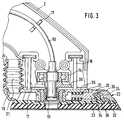
- FIG. 3shows an enlarged detail of the front region of the hand-held power tool according to FIG. 1
- FIG. 4shows a top view of the tool holder
- FIGS. 5 and 6oscillating elements of the tool holder according to FIG. 4
- FIG. 7shows a side view of FIG. 4 in particular 8, a side view of the grinding plate, according to FIG. 8, in section
- FIG. 10a bellows for dust extraction to be coupled with the tool holder
- FIG. 11a side view of the tool holder from the side of the bellows 12 shows a view of the tool holder from below
- FIG. 13shows a top view of a further embodiment of a grinding plate
- FIG. 14shows the side view of the grinding plate according to FIG. 13.
- the electric hand machine tool shown in FIG. 1is designed as an orbital sander 1, which has a machine housing 2 in which a motor 3 is arranged.
- the orbital sander 1carries an on / off switch 4 at the top, in particular for operation with the thumb.
- a motor control adjusting wheel 5is arranged in the rear area of the machine housing 2.
- An electrical connection line 6 with a protective sleeve 7emerges from the rear of the machine housing 2.
- the orbital sander 1carries a sanding plate 8 for receiving sanding sheets (not shown), which is detachably attached to a tool holder 9 in a latching manner.
- Rotations of the motor 3are transmitted to the tool holder 9 and thus to the grinding plate 8 by a flexible shaft 10, which is guided in the machine housing 2 via a lateral vibration limitation 11.
- the flexible shaft 10ends at one end in an eccentric pin 12, with which it is on the one hand via a needle bearing 13 on the tool holder 9 and on the other hand via a lower roller bearing 14 on the machine housing 2 is rotatably supported near the tool holder 9 and facing it.
- the flexible shaft 10is coupled to a motor shaft (not explained in more detail) via a plug-in coupling 15.
- the flexible shaft 10is rotatably mounted in an upper roller bearing 16 in the machine housing 2.
- the tool holder 9is secured via leaf spring-like oscillating elements 17, 18 on the machine housing 2 against loss and against rotation.
- a bellows 21is arranged as an elastic connecting element between a mouth 19 for dust discharge on the tool holder 9 and a dust removal channel 20 in the machine housing 2, through which dust can flow freely through the circular movement of the tool holder 9.
- the tool holder 9carries a control button 22 which is easily accessible from the front or from above and which can be moved to the rear and is integrally connected to a bolt 23.
- a control button 22which is easily accessible from the front or from above and which can be moved to the rear and is integrally connected to a bolt 23.
- latch 23engages in a locking hook 24 of the grinding plate 8 and thereby holds the grinding plate 8 on the tool holder 9.
- FIG. 3the machine housing 2, the flexible shaft 10, the rear and the front oscillating element 17, 18, the bellows 21, the lower roller bearing 14 and the eccentric pin 12.
- a needle bearing 29can be seen between the tool holder 9 and the eccentric pin 12, a compensating mass 30 arranged on the eccentric pin 12 for Reduce the imbalance occurring during the eccentric movement of the tool holder 9 with the grinding plate 8.
- the control button 22is displaceably supported against the force of a compression spring 31.
- the control button 22On the side facing the grinding plate 8, the control button 22 has a recess 32 whose left-hand contour has two inclined surfaces 33, 34 which form a beak-like tip. This tip is opposed to a similar tip of a latching hook 24, which is formed in one piece from a fixed sanding plate 35.
- the locking hook 24carries two counter bevels 36, 37.
- the upper inclined surface 33 of the bolt 23 or the control button 22hooks and braces, engaging under the locking hook 24, against the lower counter bevel 37 and thus stabilizes the locking of the grinding plate 8 on the tool holder 9, so that in the tensioned state, the grinding plate 8 is pressed firmly against the tool holder 9.
- the control button 22does not have to be moved backwards, since the latching hook 24 slides on the latch 23, automatically pushes it back and latches.
- FIG 4the top view of the tool holder 9 is shown with the vibrating elements 17, 18 and the mouth 19 of the dust removal channel 20 and with two engagement openings 39, 40, the opening 41 for the needle bearing 13 or for the eccentric pin 12 and in the front corner 42 the opening 43 for receiving the control button 22.
- FIGS. 5 and 6the vibrating elements 17, 18 shown. It is clear from this that the rear oscillating element 17 is a pair of three individual oscillating columns and the front oscillating element 18 consists of four individual oscillating columns.
- Figure 7illustrates the arrangement of the vibrating elements 17, 18 on the tool holder 9 and shows in the side view of Figure 4 along the section line of the arrows YY the T-profile of the vibrating elements 17, 18, which with their upper transverse blades in corresponding, unspecified recesses of the machine housing 2 are arranged positively.
- FIG. 8shows a view from below of the grinding plate 8 and clarifies its triangular outline with side edges 44, 45, 46 curved outwards.
- suction openings 47 on a common pitch circle and the support claws 48explained for FIG. 9 49, 50, 51, 52, 53 or the three locking hooks 24 near the grinding plate corners 54, 55, 56.
- the arrows XXshow the section for FIG. 9.
- FIG. 9shows the side view of the grinding plate 8 along the arrows X-X according to FIG. 8.
- the grinding plate 8consists of a grinding plate plate 35, in particular made of rigid plastic, and of a sanding pad cushion 57, in particular made of flexible plastic.
- the sanding plate 8has a hook and loop fastener system (not described in more detail) to which the sanding sheets (not shown) or other tools with velor backing fit.
- the grinding plate plate 35On the side facing the tool holder 9, the grinding plate plate 35 carries in each grinding plate corner 54, 55, 56 mutually opposite support claws 48, 49, 50, 51, 52, 53 as well as a locking hook 24 symmetrically divided by the bisector of the angle Pointed, outwardly facing, obliquely arranged support and holding surfaces 58, 59.
- Die Locking hooks 24also have counter-bevels 36, 37 tapering towards a tip and facing inwards towards the center of the grinding plate 8, which are provided for latching the bolt 23 of the control button 22 (FIG. 3).
- the grinding plate 8can be assigned as desired to the corners of the tool holder.
- the function of the support claws 48, 49, 50, 51, 52, 53changes depending on whether they engage in the engagement openings 39, 40 of the tool holder 9 and thus hold the grinding plate 8 on the tool holder 9 like a hinge or whether the support claws 48, 49, 50, 51, 52, 53 act as an elastic spacer spring, slide on the support bevels 62, 63, 64, 65 (FIG. 12) and hold the grinding plate 8 biased against the tool holder 9, so to speak.
- FIG. 10shows the enlargement of a bellows 21 according to FIGS. 1 and 3 with a flat, rectangular cross section, corresponding to the mouth 19 according to FIG. 4.
- FIGS. 11 and 12show a view of the tool holder 9 from behind and from below.
- the cams 60, 61can be seen, which cooperate with the support claws 48, 49, 50, 51, 52, 53 and ensure play-free attachment of the grinding plate 8 to the tool holder 9.
- the same taskhave bevels 62, 63, 64, 65, which are arranged on the inside on the side surfaces 66, 67 of the tool holder 9 and, sliding on the support claws 48, 49, 50, 51, 52, 53 for clamping between the grinding plates 8 and Ensure tool holder 9 and thus ensure a play-free arrangement.
- the sliding guide 68 for receiving the control button 22can be seen particularly well from below.
- FIGS. 13 and 14show a special grinding plate 70.
- the special grinding plate 70analogous to grinding plate 8 according to FIGS. 8, 9, carries supporting claws 72, 73, 74, 75, 76, 77, which are opposite each other in mirror image, in each inner contour corner 81, 82, and one due to the longitudinal bisecting line of symmetrically divided locking hooks 71.
- the support claws 72, 73, 74, 75, 76, 77have outward-pointing, beak-like, obliquely arranged support and holding surfaces 48, 85.
- the locking hook 71has inwards, towards the center of the grinding plate 70 facing counter-bevels 86, 87, which are provided for latching the bolt 23 of the control button 22 (Fig. 3).
- the grinding plate 70can only be coupled to the tool holder 9 in the longitudinal direction, because only its forwardly extended area is intended for grinding and not, as in the exemplary embodiment according to FIGS. 8, 9, the area immediately below the tool holder 9 .
- a sanding plate 70 according to FIGS. 13, 14it is possible to grind in narrow spaces, for example louvres from shutters, doors or, for example, closely spaced radiator fins.
- the grinding plate 8which can be released via the operating button 22 without an auxiliary tool, can be exchanged particularly quickly for further grinding plates (not shown), preparatively equipped with sanding sheets of different grain sizes, or for a special grinding plate 70 according to FIGS. 13, 14. Time-consuming loosening of the Velcro fastener between sanding plate 8 and sanding sheet is eliminated because the respective sanding sheet can remain on its sanding plate. In this way, grinding work of different surface qualities can be carried out conveniently in alternation.
- the grinding plate 8 and / or the tool holder 9rise like a truncated pyramid over their base area, in particular together, form a truncated pyramid so that the outermost edges of the sanding sheet are always in the field of vision of the user of the orbital sander.
- the channel outlet 25 for removal of grinding dust or the likeis arranged asymmetrically at the rear end of the machine housing 2 in a machine housing shell half 27, the channel outlet 25 can be made with high accuracy, so that hoses or the like. For dust removal particularly tight and are securely connectable against unwanted loosening.
- a correspondingly suitable separating plateis clipped on analogously to the type of fastening of the grinding plates mentioned.
- this cutting platefor example, floor coverings and wallpapers can be easily removed from the surface.
- a scraper and / or a sawis used instead of a grinding plate attachable to the tool holder.
- the tool holder with the grinding plateis mounted in a lockable joint on the machine housing, so that the grinding plate plane or the like can be pivoted to adapt the orbital sander to angled, difficult to access workpieces.
Landscapes
- Engineering & Computer Science (AREA)
- Mechanical Engineering (AREA)
- Finish Polishing, Edge Sharpening, And Grinding By Specific Grinding Devices (AREA)
Abstract
Description
Translated fromGermanDie Erfindung geht aus von einer Handwerkzeugmaschine nach der Gattung des Anspruchs 1.The invention relates to a handheld power tool according to the preamble of claim 1.
Durch die US 3 160 995 ist eine Handwerkzeugmaschine zum randnahen Schleifen von Flächen, insbesondere in Ecken bzw. entlang von Hohlkehlen, bekannt. Die Handwerkzeugmaschine hat einen Schleifteller mit dreieckiger Grundfläche. Dessen Arbeitsbewegung erfolgt um eine feststehende, zur Grundfläche normal verlaufende Achse hin- und her schwenkend. Dabei durchstößt die Achse den Schleifteller geometrisch nahe einer nach vorn weisenden Ecke. Der Winkel der Ecke im vorderen Bereich des Schleiftellers ist kleiner als 90°, damit der Schleifteller bis in äußerste, randnahe Bereiche von Ecken bzw. Hohlkehlen zum Schleifen einsetzbar ist. Bei einer weiterentwickelten, derartigen Handwerkzeugmaschine mit den Schleifteller geometrisch mittig durchstoßender Achse sind die Ränder des Schleifwerkzeugs gewölbt, wie auch bei Bügeleisen bekannt, zum kantenbündigen Schleifen an schwer zugänglichen Stellen.US 3 160 995 discloses a hand tool for grinding surfaces close to the edge, in particular in corners or along fillets. The hand tool has a sanding plate with a triangular base. Its working movement swings back and forth about a fixed axis that is normal to the base. The axis penetrates the grinding disc geometrically near a forward-facing corner. The angle of the corner in the front area of the sanding plate is less than 90 °, so that the sanding plate can be used for sanding in the outermost, near-edge areas of corners or fillets. In a further developed hand tool of this type with the grinding disc geometrically penetrating in the center, the edges of the grinding tool are curved, as is also known in the case of irons, for grinding flush at hard-to-reach places.
Der als gleichseitiges Dreieck, bügeleisenartig mit gewölbten Seitenkanten ausgestaltete Grundriß des Schleiftellers hat, wie alle derartigen Dreiecke, drei Eckwinkel, je kleiner als 90°.The plan of the sanding plate, designed as an equilateral triangle, like an iron with curved side edges, has, like all such triangles, three corner angles, each less than 90 °.
Darüber hinaus sind Handwerkzeugmaschinen mit rechteckigem Schleifteller bekannt, der mittels Exzenterantrieb eine gefesselte, kreisende Bewegung ausführt. Diese Handwerkzeugmaschinen werden als Schwingschleifer bezeichnet, obwohl ihr Werkzeug keine im eigentlichen Sinn schwingende Bewegung ausführt.In addition, hand-held machine tools with a rectangular grinding plate are known which, by means of an eccentric drive, perform a tied, circular movement. These hand-held machine tools are referred to as orbital sanders, although their tool does not actually perform any oscillating movement.
Eine Weiterentwicklung der Schwingschleifer führte zum Exzenterschleifer mit ungefesselt kreisendem und rotierendem Schleifteller. Dessen Bewegung ist durch Einstellen mehrerer, unterschiedlicher Bearbeitungsstufen steuerbar.A further development of the orbital sander led to the eccentric sander with untied orbiting and rotating sanding disc. Its movement can be controlled by setting several different processing levels.
Die bekannten Handwerkzeugmaschinen sind leistungsfähig aber verhältnismäßig aufwendig gebaut. Sie haben ein hohes Gewicht, einen hohen Energiebedarf, eine hohe Geräuschentwicklung und benötigen zum Werkzeugwechsel, d.h. Wechsel des Schleiftellers, ein Hilfswerkzeug.The known hand machine tools are powerful but relatively expensive to build. They have a high weight, a high energy requirement, a high level of noise and need to change tools, i.e. Changing the sanding plate, an auxiliary tool.
Die erfindungsgemäße Handwerkzeugmaschine mit den kennzeichnenden Merkmalen des Anspruchs 1 hat demgegenüber den Vorteil einfacher Bauart, geringer Geräuschentwicklungen, geringen Energiebedarfs, einfacher Herstellung, kleiner bewegter Massen, bequemen schnellen Wechsels des Werkzeugs, insbesondere des Schleifblattes gemeinsam mit dem Schleifteller, ohne Hilfswerkzeug.The hand tool according to the invention with the characterizing features of claim 1, in contrast, has the advantage of simple design, low noise, low energy requirements, simple manufacture, small moving masses, convenient quick change of the tool, in particular the sanding sheet together with the grinding plate, without auxiliary tools.
Weitere vorteilhafte Ausgestaltungen der Erfindung ergeben sich aus den abhängigen Ansprüchen.Further advantageous embodiments of the invention result from the dependent claims.
In der nachfolgenden Beschreibung ist anhand der zugehörigen Zeichnung ein Ausführungsbeispiel der Erfindung näher erläutert.In the following description, an embodiment of the invention is explained in more detail with reference to the accompanying drawing.
Es zeigen Figur 1 die Seitenansicht einer erfindungsgemäßen Handwerkzeugmaschine, Figur 2 eine Draufsicht der Handwerkzeugmaschine gemäß Figur 1, Figur 3 einen vergrößerten Ausschnitt des vorderen Bereichs der Handwerkzeugmaschine gemäß Figur 1, Figur 4 eine Draufsicht des Werkzeughalters, Figur 5 und 6 Schwingelemente des Werkzeughalters gemäß Figur 4, Figur 7 eine Seitenansicht der Figur 4 insbesondere der Schwingelemente, Figur 8 eine Ansicht des Schleiftellers von unten, Figur 9 eine Seitenansicht des Schleiftellers, gemäß Figur 8, im Schnitt, Figur 10 einen mit dem Werkzeughalter zu koppelnden Faltenbalg zur Staubabsaugung, Figur 11 eine Seitenansicht des Werkzeughalters von der Seite des Faltenbalgs her, Figur 12 eine Ansicht des Werkzeughalters von unten, Figur 13 eine Draufsicht auf ein weiteres Ausführungsbeispiel eines Schleiftellers und Figur 14 die Seitenansicht des Schleiftellers gemäß Figur 13.FIG. 1 shows the side view of a hand tool according to the invention, 2 shows a plan view of the hand-held power tool according to FIG. 1, FIG. 3 shows an enlarged detail of the front region of the hand-held power tool according to FIG. 1, FIG. 4 shows a top view of the tool holder, FIGS. 5 and 6 oscillating elements of the tool holder according to FIG. 4, FIG. 7 shows a side view of FIG. 4 in particular 8, a side view of the grinding plate, according to FIG. 8, in section, FIG. 10 a bellows for dust extraction to be coupled with the tool holder, FIG. 11 a side view of the tool holder from the side of the
Die in Figur 1 gezeigte Elektrohandwerkzeugmaschine ist als Schwingschleifer 1 ausgestaltet, der ein Maschinengehäuse 2 besitzt, in dem ein Motor 3 angeordnet ist. Oben trägt der Schwingschleifer 1 einen Ein- und Ausschalter 4, insbesondere zur Bedienung mit dem Daumen. Im hinteren Bereich des Maschinengehäuses 2 ist ein Motor-Regelungsstellrad 5 angeordnet. Nach hinten tritt aus dem Maschinengehäuse 2 eine elektrische Anschlußleitung 6 mit einer Schutzhülse 7 aus. Vorn trägt der Schwingschleifer 1 einen Schleifteller 8 zur Aufnahme von nichtdargestellten Schleifblättern, der abnehmbar an einem Werkzeughalter 9 überrastend befestigt ist.The electric hand machine tool shown in FIG. 1 is designed as an orbital sander 1, which has a
Auf den Werkzeughalter 9 und damit den Schleifteller 8 werden Drehungen des Motors 3 durch eine biegsame Welle 10 übertragen, die über eine seitliche Schwingungsbegrenzung 11 im Maschinengehäuse 2 geführt ist.
Die biegsame Welle 10 endet einenends in einem Exzenterzapfen 12, mit dem sie einerseits über ein Nadellager 13 am Werkzeughalter 9 und andererseits über ein unteres Wälzlager 14 am Maschinengehäuse 2 nahe dem Werkzeughalter 9 und diesem zugewandt drehbar gelagert ist. Auf der dem Werkzeughalter 9 abgewandten Seite ist die biegsame Welle 10 über eine Steckkupplung 15 mit einer nicht näher erläuterten Motorwelle gekuppelt. Außerdem ist in der Nähe der Steckkupplung 15 die biegsame Welle 10 in einem oberen Wälzlager 16 im Maschinengehäuse 2 drehbar gelagert.Rotations of the motor 3 are transmitted to the
The
Der Werkzeughalter 9 ist über blattfederartige Schwingelemente 17, 18 am Maschinengehäuse 2 gegen Verlieren und gegen Drehmitnahme gesichert befestigt.The
Zwischen einer Mündung 19 zum Staubaustritt am Werkzeughalter 9 und einem Staubabtransportkanal 20 im Maschinengehäuse 2 ist als elastisches Verbindungselement ein Faltenbalg 21 angeordnet, durch den ungehindert der kreisenden Bewegung des Werkzeughalters 9 Staub abströmen kann.A
Im vorderen Eck-Bereich trägt der Werkzeughalter 9 eine von vorn bzw. von oben gut zugängliche Bedientaste 22, die nach hinten verschiebbar ist und einstückig mit einem Riegel 23 verbunden ist. Dieser - nachfolgend zu Figur 3 erläuterte - Riegel 23 greift in einen Rasthaken 24 des Schleiftellers 8 ein und hält dadurch den Schleifteller 8 am Werkzeughalter 9 fest.In the front corner area, the
In Figur 2 sind die zuvor beschriebenen Einzelheiten von oben deutlich erkennbar, so die Bedientaste 22, der dreieckige Werkzeughalter 9 mit Schleifteller 8, der Ein- und Ausschalter 4, die elektrische Anschlußleitung 6 und das Motor-Regelungsstellrad 5. Über die Figur 1 hinausgehend sind in Figur 2 erkennbar ein Kanalaustritt 25 sowie eine Trennfuge 26, die den Aufbau des Maschinengehäuses 2 aus zwei unsymmetrischen Halbschalen 27, 28 zeigt.In Figure 2, the details described above are clearly visible from above, so the
In Figur 3 sind die zuvor beschriebenen Einzelheiten deutlicher zu erkennen: Das Maschinengehäuse 2, die biegsame Welle 10, hinteres und vorderes Schwingelement 17, 18, der Faltenbalg 21, das untere Wälzlager 14 und der Exzenterzapfen 12. Über die Figuren 1 und 2 hinaus ist ein Nadellager 29 zwischen dem Werkzeughalter 9 und dem Exzenterzapfen 12 erkennbar, eine auf dem Exzenterzapfen 12 angeordnete Ausgleichsmasse 30 zum Mindern der bei der Exzenterbewegung des Werkzeughalters 9 mit Schleifteller 8 auftretenden Unwucht.The details described above can be seen more clearly in FIG. 3: the machine housing 2, the
Weiter werden die Ausgestaltung des schalenartigen Werkzeughalters 9 und der Bedientaste 22 klar:
Die Bedientaste 22 ist nach hinten verschiebbar gelagert gegen die Kraft einer Druckfeder 31. Auf der dem Schleifteller 8 zugewandten Seite trägt die Bedientaste 22 eine Ausnehmung 32, deren seitlich linke Kontur zwei Schrägflächen 33, 34 aufweist, die eine schnabelartige Spitze bilden. Dieser Spitze steht eine ähnliche Spitze eines Rasthakens 24 gegenüber, der einstückig aus einer festen Schleiftellerplatte 35 ausgeformt ist. Der Rasthaken 24 trägt zwei Gegenschrägen 36, 37. Die obere Schrägfläche 33 des Riegels 23 bzw. der Bedientaste 22 verhakt und verspannt sich, den Rasthaken 24 untergreifend, gegen die untere Gegenschräge 37 und stabilisiert so die Verriegelung des Schleiftellers 8 am Werkzeughalter 9, so daß im gespannten Zustand der Schleifteller 8 fest gegen den Werkzeughalter 9 gepreßt wird. Außerdem muß durch die Wirkung der unteren Schrägfläche 34 beim Montieren des Schleiftellers 8 am Werkzeughalter 9 die Bedientaste 22 nicht nach hinten verschoben werden, da der Rasthaken 24 am Rie- gel 23 aufgleitet, diesen selbsttätig zurückschiebt und überrastet.Furthermore, the design of the shell-
The
In Figur 4 ist die Draufsicht auf den Werkzeughalter 9 gezeigt mit den Schwingelementen 17, 18 und der Mündung 19 des Staubabtransportkanals 20 sowie mit zwei Eingriffsöffnungen 39, 40, der Öffnung 41 für das Nadellager 13 bzw. für den Exzenterzapfen 12 sowie in der vorderen Ecke 42 die Öffnung 43 zur Aufnahme der Bedientaste 22.In Figure 4, the top view of the
In den Figuren 5 und 6 sind als Einzelheit die Schwingelemente 17, 18 gezeigt. Daraus wird deutlich, daß das hintere Schwingelement 17 ein Paar aus je drei Einzelschwingsäulen ist und das vordere Schwingelement 18 aus vier Einzel-Schwingssäulen besteht.In FIGS. 5 and 6, the
Figur 7 verdeutlicht die Anordnung der Schwingelemente 17, 18 auf dem Werkzeughalter 9 und zeigt in der Seitenansicht der Figur 4 entlang der Schnittlinie der Pfeile Y-Y das T-Profil der Schwingelemente 17, 18, die mit ihren oberen Querblättern in entsprechende, nicht näher bezeichnete Aussparungen des Maschinengehäuses 2 formschlüssig angeordnet sind.Figure 7 illustrates the arrangement of the
Figur 8 zeigt eine Ansicht von unten auf den Schleifteller 8 und verdeutlicht dessen dreieckigen Grundriß mit nach außen gewölbten Seitenkanten 44, 45, 46. Darüber hinaus wird deutlich, die Anordnung von Absaugöffnungen 47 auf einem gemeinsamen Teilkreis und die zu Figur 9 erklärten Stützkrallen 48, 49, 50, 51, 52, 53 bzw. der drei Rasthaken 24 nahe den Schleiftellerecken 54, 55, 56. Die Pfeile X-X zeigen den Schnittverlauf für Figur 9.FIG. 8 shows a view from below of the grinding plate 8 and clarifies its triangular outline with
Figur 9 zeigt die Seitenansicht des Schleiftellers 8 entlang der Pfeile X-X nach Figur 8. Hier wird deutlich, daß der Schleifteller 8 aus einer Schleiftellerplatte 35, insbesondere aus festem Kunststoff, und aus einem Schleiftellerkissen 57, insbesondere aus weichelastischem Kunststoff besteht. Auf seiner Unterseite trägt der Schleifteller 8 ein nicht näher bezeichnetes Klettverschlußsystem mit Häkchen, zu dem nichtdargestellte Schleifblätter bzw. andere Werkzeuge mit Velourrücken passen.FIG. 9 shows the side view of the grinding plate 8 along the arrows X-X according to FIG. 8. It is clear here that the grinding plate 8 consists of a
Auf der dem Werkzeughalter 9 zugewandten Seite trägt die Schleiftellerplatte 35 in jeder Schleiftellerecke 54, 55, 56 einander spiegelbildlich gegenüberliegende Stützkrallen 48, 49, 50, 51, 52, 53 sowie eine, durch die Winkelhalbierende symmetrisch geteilten Rasthaken 24. Die Stützkrallen haben zu einer Spitze zulaufende, nach außen weisende schräg angeordnete Stütz- und Halteflächen 58, 59. Die Rasthaken 24 haben ebenfalls zu einer Spitze zulaufende, nach innen zur Mitte des Schleiftellers 8 gewandte, Gegenschrägen 36, 37, die zum Einrasten des Riegels 23 der Bedientaste 22 (Fig. 3) vorgesehen sind.On the side facing the
Der Schleifteller 8 kann aufgrund seines vollständig symmetrischen Aufbaus mit den Schleiftellerecken 54, 55, 56 beliebig den Ecken des Werkzeughalters zugeordnet werden. Hierbei wechselt die Funktion der Stützkrallen 48, 49, 50, 51, 52, 53 je nachdem, ob diese in die Eingriffsöffnungen 39, 40 des Werkzeughalters 9 rasten und damit den Schleifteller 8 am Werkzeughalter 9 scharnierartig festhalten oder ob die Stützkrallen 48, 49, 50, 51, 52, 53 als elastische Distanzfeder wirken, an den Stützschrägen 62, 63, 64, 65 (Figur 12) aufgleiten und den Schleifteller 8 gegenüber dem Werkzeughalter 9 sozusagen vorgespannt festhalten.Due to its completely symmetrical structure with the
Die Figur 10 zeigt die Vergrößerung eines Faltenbalgs 21 gemäß den Figuren 1 und 3 mit flachem, rechteckigem Querschnitt, entsprechend der Mündung 19 gemäß Figur 4.FIG. 10 shows the enlargement of a
Die Figuren 11 und 12 zeigen eine Ansicht des Werkzeughalters 9 von hinten bzw. von unten. Dabei wird die gemäß der Figuren 4 bis 7 nicht sichtbare symmetrische Anordnung der Schwingelemente 17, 18 deutlich. Darüberhinaus werden die Nocken 60, 61 erkennbar, die mit den Stützkrallen 48, 49, 50, 51, 52, 53 zusammenwirken und eine spielfreie Befestigung des Schleiftellers 8 am Werkzeughalter 9 sichern.
Die gleiche Aufgabe haben Stützschrägen 62, 63, 64, 65, die innen auf den Seitenflächen 66, 67 des Werkzeughalters 9 angeordnet sind und, aufgleitend auf die Stützkrallen 48, 49, 50, 51, 52, 53 für ein Verspannen zwischen Schleifteller 8 und Werkzeughalter 9 sorgen und damit eine spielfreie Anordnung sichern. Weiter ist von unten besonders gut erkennbar die Verschiebeführung 68 zur Aufnahme der Bedientaste 22.FIGS. 11 and 12 show a view of the
The same task have bevels 62, 63, 64, 65, which are arranged on the inside on the side surfaces 66, 67 of the
In den Figuren 13 und 14 ist ein Sonderschleifteller 70 dargestellt. Auf der dem Werkzeughalter 9 zugewandten Seite trägt der Sonderschleifteller 70, analog zu Schleifteller 8 gemäß der Figuren 8, 9, in jeder Innenkontur-Ecke 81, 82, 83 einander spiegelbildlich gegenüberliegende Stützkrallen 72, 73, 74, 75, 76, 77 sowie einen durch die längs verlaufende Winkelhalbierende symmetrisch geteilten Rasthaken 71. Die Stützkrallen 72, 73, 74, 75, 76, 77 haben nach außen weisende, schnabelähnliche schräg angeordnete Stütz- und Halteflachen 48, 85. Der Rasthaken 71 hat nach innen, zur Mitte des Schleiftellers 70 gewandte, Gegenschrägen 86, 87, die zum Einrasten des Riegels 23 der Bedientaste 22 (Fig. 3) vorgesehen sind.FIGS. 13 and 14 show a special grinding
Der Schleifteller 70 kann aufgrund seines unsymmetrischen Aufbaus nur in Längsrichtung mit dem Werkzeughalter 9 gekoppelt werden, weil nur sein nach vorn verlängerter Bereich zum Schleifen vorgesehen ist und nicht, wie bei dem Ausführungsbeispiel gemäß Figur 8, 9, der unmittelbar unter dem Werkzeughalter 9 liegende Bereich. Deutlich wird die Anordnung des nach vorn verlagerten Klettverschlußbereichs 88.Due to its asymmetrical structure, the grinding
Mit einem Schleifteller 70 gemäß Figur 13, 14 ist es möglich, in engen Zwischenräumen zu schleifen, beispielsweise Lamellen von Fensterläden, Türen oder beispielsweise eng aneinander grenzende Heizkörperrippen.With a sanding
Nach Einschalten des Motors 3 über den Ein- und Ausschalter 4 dreht sich die Motorwelle und damit die flexible Welle 10 mit dem Exzenterzapfen 12. Der über die Schwingelemente 17, 18 im Maschinengehäuse 2 in einem sicheren Abstand gegen Verdrehen und Verliegen gesicherte Werkzeughalter 9 führt eine elliptische Kreisbewegung aus, wobei er dem Exzenterzapfen 12 folgt. Dadurch, daß die elliptische Bewegung längs nach vorn gerichtet ist, können besonders gut mit den gewölbten Außenkanten 44, 45, 46 des Schleiftellers 8 bzw. der Schleifblätter Kanten- bzw. Hohlkehlen oder andere, schwer zugängliche Bereiche an Werkstücken bündig, kantennah bearbeitet werden.After switching on the motor 3 via the on / off
Der ohne Hilfswerkzeug über die Bedientaste 22 lösbare Schleifteller 8 kann gegen weitere, nichtdargestellte Schleifteller, vorbereitend bestückt mit Schleifblättern unterschiedlicher Körnung oder gegen einen Sonderschleifteller 70 gemäß Figur 13, 14 besonders schnell gewechselt werden. Zeitaufwendiges Lösen des Klettverschlusses zwischen Schleifteller 8 und Schleifblatt entfällt, weil das jeweilige Schleifblatt an seinem Schleifteller verbleiben kann. So können Schleifarbeiten unterschiedlicher Oberflächengüte im Wechsel bequem durchgeführt werden.The grinding plate 8, which can be released via the
Für die Übersichtlichkeit der zu bearbeitenden Flächen bzw. Kanten und die Kontrolle des Schwingschleifers 1 ist es vorteilhaft, daß sich der Schleifteller 8 und/oder der Werkzeughalter 9 pyramidenstumpfartig über deren Grundfläche erheben, insbesondere gemeinsam, bündig einen Pyramidenstumpf bilden, so daß die äußersten Kanten des Schleifblattes stets im Sichtfeld des Benutzers des Schwingschleifers liegen.For the clarity of the surfaces or edges to be processed and the control of the orbital sander 1, it is advantageous that the grinding plate 8 and / or the
Dadurch, daß der Kanalaustritt 25 zum Abtransport von Schleifstaub oder dergl. asymmetrisch am hinteren Ende des Maschinengehäuses 2 in einer Maschinengehäuse-Schalenhälfte 27 angeordnet ist, kann der Kanalaustritt 25 mit hoher Genauigkeit gefertigt werden, so daß Schläuche oder dergl. zum Staubabtransport besonders dicht und sicher gegen ungewolltes Lösen anschließbar sind.Characterized in that the
Bei einem nicht dargestellten Ausführungsbeispiel der Erfindung ist an Stelle der Schleifteller 8 bzw. 70 gemäß Figur 8 bzw. 13 ein entsprechend passendes Trennblech analog zur Befestigungsart der genannten Schleifteller angeklipst. Mit diesem Schneidblech können beispielsweise Fußbodenbeläge und Tapeten bequem vom Untergrund gelöst werden.In an embodiment of the invention, not shown, instead of the grinding
Bei einem anderen nichtdargestellten Ausführungsbeispiel der Erfindung ist anstelle eines Schleiftellers ein Schaber und/oder eine Säge an den Werkzeughalter ansetzbar.In another exemplary embodiment of the invention, not shown, a scraper and / or a saw is used instead of a grinding plate attachable to the tool holder.
Bei einem weiteren nichtdargestellten Ausführungsbeispiel der Erfindung ist der Werkzeughalter mit dem Schleifteller in einem arretierbaren Gelenk am Maschinengehäuse gelagert, so daß die Schleiftellerebene oder dergl. zur Anspassung des Schwingschleifers an verwinkelte, schwer zugängliche Werkstücke schwenkbar ist.In a further embodiment of the invention, not shown, the tool holder with the grinding plate is mounted in a lockable joint on the machine housing, so that the grinding plate plane or the like can be pivoted to adapt the orbital sander to angled, difficult to access workpieces.
Claims (16)
Translated fromGermandaß der Werkzeughalter (9) mit mit der Grundfläche eines Schleiftellers (8) im wesentlichen übereinstimmender, insbesondere dreieckiger, Grundfläche bzw. Kontur, schalenartig ausgestaltet ist und sich mit seinem äußeren Rand (69) auf dem Schleifteller (8) abstützt.Hand tool (1) for surface machining with a machine housing (2) which accommodates a motor (3) and which, preferably at the front, carries a rotating, rotating or oscillating tool (8) on a tool holder (9), in particular a grinding disc (8) with a triangular one Base area for holding triangular sanding sheets with Velcro fastener, characterized in that
that the tool holder (9) is designed in a shell-like manner with the base surface of a grinding plate (8) essentially matching, in particular triangular, base surface or contour and is supported with its outer edge (69) on the grinding plate (8).
Priority Applications (1)
| Application Number | Priority Date | Filing Date | Title |
|---|---|---|---|
| EP95118775AEP0710527B1 (en) | 1993-02-04 | 1994-02-03 | Handtool for machining surfaces |
Applications Claiming Priority (3)
| Application Number | Priority Date | Filing Date | Title |
|---|---|---|---|
| DE4303044ADE4303044A1 (en) | 1993-02-04 | 1993-02-04 | Hand tool for surface processing |
| DE4303044 | 1993-02-04 | ||
| EP95118775AEP0710527B1 (en) | 1993-02-04 | 1994-02-03 | Handtool for machining surfaces |
Related Child Applications (2)
| Application Number | Title | Priority Date | Filing Date |
|---|---|---|---|
| EP95118775.6Division-Into | 1994-02-03 | ||
| EP95118775ADivisionEP0710527B1 (en) | 1993-02-04 | 1994-02-03 | Handtool for machining surfaces |
Publications (3)
| Publication Number | Publication Date |
|---|---|
| EP0610801A1true EP0610801A1 (en) | 1994-08-17 |
| EP0610801B1 EP0610801B1 (en) | 1996-07-10 |
| EP0610801B2 EP0610801B2 (en) | 2002-09-04 |
Family
ID=25922754
Family Applications (1)
| Application Number | Title | Priority Date | Filing Date |
|---|---|---|---|
| EP94101587AExpired - LifetimeEP0610801B2 (en) | 1993-02-04 | 1994-02-03 | Handtool for machining surfaces |
Country Status (2)
| Country | Link |
|---|---|
| EP (1) | EP0610801B2 (en) |
| DE (1) | DE4303044A1 (en) |
Cited By (17)
| Publication number | Priority date | Publication date | Assignee | Title |
|---|---|---|---|---|
| EP0699505A1 (en)* | 1994-08-25 | 1996-03-06 | Black & Decker Inc. | Abrasive sheets |
| WO1997042002A1 (en)* | 1996-05-02 | 1997-11-13 | Robert Bosch Gmbh | Electric hand-operated grinder |
| US5743791A (en)* | 1995-02-09 | 1998-04-28 | Porter Cable Corporation | Sanding system |
| US5759094A (en)* | 1995-02-09 | 1998-06-02 | Porter-Cable Corporation | In-line detail sander |
| US5772498A (en)* | 1996-03-08 | 1998-06-30 | Robert Bosch Gmbh | Electrical hand grinder |
| US5855504A (en)* | 1996-05-02 | 1999-01-05 | Robert Bosch Gmbh | Hand-operated orbital sander |
| US5888128A (en)* | 1996-05-02 | 1999-03-30 | Robert Bosch Gmbh | Hand grinder |
| EP0953407A1 (en)* | 1998-04-29 | 1999-11-03 | Black & Decker Inc. | Powered oscillating hand tool |
| US6129618A (en)* | 1996-08-09 | 2000-10-10 | Robert Bosch Gmbh | Oscillating sander |
| CN1082414C (en)* | 1996-05-02 | 2002-04-10 | 罗伯特-博希股份公司 | Hand electric polisher |
| WO2005108010A1 (en)* | 2004-04-01 | 2005-11-17 | Robert Bosch Gmbh | Hand-guided grinding machine, grinding machine holding unit, and grinding machine housing |
| CN100446923C (en)* | 2002-10-14 | 2008-12-31 | 罗伯特·博施有限公司 | Grinding plate for hand electric grinder and its making method |
| DE10132885B4 (en)* | 2001-07-06 | 2009-01-02 | Robert Bosch Gmbh | hand grinder |
| CN102310352A (en)* | 2010-07-05 | 2012-01-11 | 创科电动工具科技有限公司 | Sander |
| US8398457B2 (en) | 2008-08-20 | 2013-03-19 | Black & Decker Inc. | Multi-sander |
| US9421682B2 (en) | 2011-07-18 | 2016-08-23 | Black & Decker Inc. | Multi-head power tool with reverse lock-out capability |
| US9956677B2 (en) | 2013-05-08 | 2018-05-01 | Black & Decker Inc. | Power tool with interchangeable power heads |
Families Citing this family (5)
| Publication number | Priority date | Publication date | Assignee | Title |
|---|---|---|---|---|
| USD389388S (en) | 1996-03-05 | 1998-01-20 | Black & Decker Inc. | Sanding sheet |
| DE29614325U1 (en)* | 1996-08-21 | 1996-10-31 | Kress-Elektrik GmbH & Co Elektromotorenfabrik, 72406 Bisingen | Hand tool for surface processing |
| USD404273S (en) | 1997-01-13 | 1999-01-19 | Black & Decker Inc. | Detail sander |
| USD409890S (en) | 1997-12-23 | 1999-05-18 | Black & Decker Inc. | Sanding sheet |
| DE102022207828A1 (en) | 2022-07-29 | 2024-02-01 | Robert Bosch Gesellschaft mit beschränkter Haftung | Connection device, tool device, tool system and machine tool system |
Citations (4)
| Publication number | Priority date | Publication date | Assignee | Title |
|---|---|---|---|---|
| GB686363A (en)* | 1950-07-14 | 1953-01-21 | Sundstrand Machine Tool Co | Improvements in or relating to rubbing machine and demountable rubbing means thereof |
| FR2529497A1 (en)* | 1982-07-02 | 1984-01-06 | Black & Decker Inc | Base plate of orbital sander |
| EP0372376A2 (en)* | 1988-12-06 | 1990-06-13 | C. & E. FEIN GmbH & Co. | Oscillating device |
| DE9205338U1 (en)* | 1991-12-15 | 1992-06-25 | Dualflex Co., Ltd., Windsor, Ontario | Polygonal shaped sanding disc |
- 1993
- 1993-02-04DEDE4303044Apatent/DE4303044A1/ennot_activeCeased
- 1994
- 1994-02-03EPEP94101587Apatent/EP0610801B2/ennot_activeExpired - Lifetime
Patent Citations (4)
| Publication number | Priority date | Publication date | Assignee | Title |
|---|---|---|---|---|
| GB686363A (en)* | 1950-07-14 | 1953-01-21 | Sundstrand Machine Tool Co | Improvements in or relating to rubbing machine and demountable rubbing means thereof |
| FR2529497A1 (en)* | 1982-07-02 | 1984-01-06 | Black & Decker Inc | Base plate of orbital sander |
| EP0372376A2 (en)* | 1988-12-06 | 1990-06-13 | C. & E. FEIN GmbH & Co. | Oscillating device |
| DE9205338U1 (en)* | 1991-12-15 | 1992-06-25 | Dualflex Co., Ltd., Windsor, Ontario | Polygonal shaped sanding disc |
Cited By (36)
| Publication number | Priority date | Publication date | Assignee | Title |
|---|---|---|---|---|
| US6045887A (en)* | 1994-08-25 | 2000-04-04 | Black & Decker Inc. | Abrasive sheets |
| EP0765713A3 (en)* | 1994-08-25 | 1997-07-30 | Black & Decker Inc | Abrasive sheets |
| EP0699505A1 (en)* | 1994-08-25 | 1996-03-06 | Black & Decker Inc. | Abrasive sheets |
| US8167683B2 (en) | 1995-02-09 | 2012-05-01 | Black & Decker Inc. | In-line sander |
| US5743791A (en)* | 1995-02-09 | 1998-04-28 | Porter Cable Corporation | Sanding system |
| US5759094A (en)* | 1995-02-09 | 1998-06-02 | Porter-Cable Corporation | In-line detail sander |
| US7438629B2 (en) | 1995-02-09 | 2008-10-21 | Black & Decker Inc. | In-line sander |
| US6257969B1 (en) | 1995-02-09 | 2001-07-10 | Porter-Cable/Delta | In-line sander |
| US6042460A (en)* | 1995-02-09 | 2000-03-28 | Porter-Cable Corporation | In-line sander |
| US5772498A (en)* | 1996-03-08 | 1998-06-30 | Robert Bosch Gmbh | Electrical hand grinder |
| CN1074970C (en)* | 1996-03-08 | 2001-11-21 | 罗伯特-博希股份公司 | Electric portable grinding machine |
| US6004194A (en)* | 1996-05-02 | 1999-12-21 | Robert Bosch Gmbh | Electric hand-operated grinder |
| CN1066994C (en)* | 1996-05-02 | 2001-06-13 | 罗伯特-博希股份公司 | Electric hand-operated grinder |
| US5888128A (en)* | 1996-05-02 | 1999-03-30 | Robert Bosch Gmbh | Hand grinder |
| CN1082414C (en)* | 1996-05-02 | 2002-04-10 | 罗伯特-博希股份公司 | Hand electric polisher |
| CN1082415C (en)* | 1996-05-02 | 2002-04-10 | 罗伯特-博希股份公司 | Hand electric polisher |
| WO1997042002A1 (en)* | 1996-05-02 | 1997-11-13 | Robert Bosch Gmbh | Electric hand-operated grinder |
| DE19617478B4 (en)* | 1996-05-02 | 2006-06-29 | Robert Bosch Gmbh | hand grinder |
| US5855504A (en)* | 1996-05-02 | 1999-01-05 | Robert Bosch Gmbh | Hand-operated orbital sander |
| US6129618A (en)* | 1996-08-09 | 2000-10-10 | Robert Bosch Gmbh | Oscillating sander |
| DE19632218B4 (en)* | 1996-08-09 | 2007-08-23 | Robert Bosch Gmbh | sander |
| EP0953407A1 (en)* | 1998-04-29 | 1999-11-03 | Black & Decker Inc. | Powered oscillating hand tool |
| CN1094086C (en)* | 1998-04-29 | 2002-11-13 | 布莱克和德克尔公司 | Powered oscillating hand tool |
| DE10132885B4 (en)* | 2001-07-06 | 2009-01-02 | Robert Bosch Gmbh | hand grinder |
| CN100446923C (en)* | 2002-10-14 | 2008-12-31 | 罗伯特·博施有限公司 | Grinding plate for hand electric grinder and its making method |
| US7771253B2 (en) | 2004-04-01 | 2010-08-10 | Robert Bosch Gmbh | Hand-guided sander, sander cradle, and sander housing |
| WO2005108010A1 (en)* | 2004-04-01 | 2005-11-17 | Robert Bosch Gmbh | Hand-guided grinding machine, grinding machine holding unit, and grinding machine housing |
| US8398457B2 (en) | 2008-08-20 | 2013-03-19 | Black & Decker Inc. | Multi-sander |
| US8613644B2 (en) | 2008-08-20 | 2013-12-24 | Black & Decker Inc. | Multi-sander |
| US8821220B2 (en) | 2008-08-20 | 2014-09-02 | Black & Decker Inc. | Power tool with interchangeable tool head |
| US9724799B2 (en) | 2008-08-20 | 2017-08-08 | Black & Decker Inc. | Power tool with interchangeable tool head |
| US10906155B2 (en) | 2008-08-20 | 2021-02-02 | Black & Decker Inc. | Power tool with interchangeable tool head |
| CN102310352A (en)* | 2010-07-05 | 2012-01-11 | 创科电动工具科技有限公司 | Sander |
| US9421682B2 (en) | 2011-07-18 | 2016-08-23 | Black & Decker Inc. | Multi-head power tool with reverse lock-out capability |
| US9956677B2 (en) | 2013-05-08 | 2018-05-01 | Black & Decker Inc. | Power tool with interchangeable power heads |
| US10661428B2 (en) | 2013-05-08 | 2020-05-26 | Black & Decker Inc. | Power tool with interchangeable tool heads |
Also Published As
| Publication number | Publication date |
|---|---|
| EP0610801B1 (en) | 1996-07-10 |
| DE4303044A1 (en) | 1994-08-11 |
| EP0610801B2 (en) | 2002-09-04 |
Similar Documents
| Publication | Publication Date | Title |
|---|---|---|
| EP0710527B1 (en) | Handtool for machining surfaces | |
| EP0610801B1 (en) | Handtool for machining surfaces | |
| EP0941804A2 (en) | Grinding device | |
| EP1419033B1 (en) | Abrasive strip carrier and hand sander | |
| DE60132939T2 (en) | power tool | |
| DE3490065T1 (en) | Device for sharpening tools | |
| EP0836544A1 (en) | Electric hand-operated grinder | |
| DE69313434T2 (en) | POWER HAND TOOL | |
| EP1305137B1 (en) | Hand-controlled grinding tool for machining round objects | |
| DE69520143T2 (en) | Sanding sheets | |
| EP3442747B1 (en) | Portable power tool having a covering device | |
| DE9320393U1 (en) | Hand tool for surface processing | |
| EP2163344A2 (en) | Manually operated machine tool with a side edge cover | |
| EP0117305B1 (en) | Work bench | |
| EP0842012B1 (en) | Orbital sander | |
| DE19807439A1 (en) | Hand power tool as an angle grinder | |
| CH666640A5 (en) | Electric hand drill or polisher attachment - includes support holder worn by operator and flexible drive shaft for auxiliary hand tool | |
| DE2332454B2 (en) | GUIDE DEVICE FOR HANDBAND SANDING MACHINES OR THE SAME | |
| DE9309965U1 (en) | Hand tool for surface processing | |
| DE29816824U1 (en) | Device for shortening and / or fine grinding toenails and fingernails | |
| EP3812100A1 (en) | Electric hand-held machine tool | |
| DE102014200039A1 (en) | Hand tool | |
| DE602004002349T2 (en) | Knife blade grinding device with unit for the restoration of the cutting edge | |
| DE10132885B4 (en) | hand grinder | |
| DE202005009030U1 (en) | Power hand sander has a clip fastening protective guard to cover the operating area of the sanding plate |
Legal Events
| Date | Code | Title | Description |
|---|---|---|---|
| PUAI | Public reference made under article 153(3) epc to a published international application that has entered the european phase | Free format text:ORIGINAL CODE: 0009012 | |
| AK | Designated contracting states | Kind code of ref document:A1 Designated state(s):CH DE FR GB IT LI | |
| 17P | Request for examination filed | Effective date:19950217 | |
| 17Q | First examination report despatched | Effective date:19950503 | |
| GRAH | Despatch of communication of intention to grant a patent | Free format text:ORIGINAL CODE: EPIDOS IGRA | |
| GRAH | Despatch of communication of intention to grant a patent | Free format text:ORIGINAL CODE: EPIDOS IGRA | |
| GRAA | (expected) grant | Free format text:ORIGINAL CODE: 0009210 | |
| AK | Designated contracting states | Kind code of ref document:B1 Designated state(s):CH DE FR GB IT LI | |
| XX | Miscellaneous (additional remarks) | Free format text:TEILANMELDUNG 95118775.6 EINGEREICHT AM 29/11/95. | |
| REF | Corresponds to: | Ref document number:59400402 Country of ref document:DE Date of ref document:19960814 | |
| REG | Reference to a national code | Ref country code:CH Ref legal event code:NV Representative=s name:SCINTILLA AG, DIREKTION | |
| ET | Fr: translation filed | ||
| ITF | It: translation for a ep patent filed | ||
| GBT | Gb: translation of ep patent filed (gb section 77(6)(a)/1977) | Effective date:19960913 | |
| PLBI | Opposition filed | Free format text:ORIGINAL CODE: 0009260 | |
| PLBQ | Unpublished change to opponent data | Free format text:ORIGINAL CODE: EPIDOS OPPO | |
| PLBF | Reply of patent proprietor to notice(s) of opposition | Free format text:ORIGINAL CODE: EPIDOS OBSO | |
| 26 | Opposition filed | Opponent name:KINZO B.V. Effective date:19970409 | |
| PLBF | Reply of patent proprietor to notice(s) of opposition | Free format text:ORIGINAL CODE: EPIDOS OBSO | |
| PLBF | Reply of patent proprietor to notice(s) of opposition | Free format text:ORIGINAL CODE: EPIDOS OBSO | |
| PLBF | Reply of patent proprietor to notice(s) of opposition | Free format text:ORIGINAL CODE: EPIDOS OBSO | |
| RDAH | Patent revoked | Free format text:ORIGINAL CODE: EPIDOS REVO | |
| APAC | Appeal dossier modified | Free format text:ORIGINAL CODE: EPIDOS NOAPO | |
| APAE | Appeal reference modified | Free format text:ORIGINAL CODE: EPIDOS REFNO | |
| APAE | Appeal reference modified | Free format text:ORIGINAL CODE: EPIDOS REFNO | |
| APAC | Appeal dossier modified | Free format text:ORIGINAL CODE: EPIDOS NOAPO | |
| APAC | Appeal dossier modified | Free format text:ORIGINAL CODE: EPIDOS NOAPO | |
| PLAW | Interlocutory decision in opposition | Free format text:ORIGINAL CODE: EPIDOS IDOP | |
| REG | Reference to a national code | Ref country code:GB Ref legal event code:IF02 | |
| PLAW | Interlocutory decision in opposition | Free format text:ORIGINAL CODE: EPIDOS IDOP | |
| PUAH | Patent maintained in amended form | Free format text:ORIGINAL CODE: 0009272 | |
| STAA | Information on the status of an ep patent application or granted ep patent | Free format text:STATUS: PATENT MAINTAINED AS AMENDED | |
| 27A | Patent maintained in amended form | Effective date:20020904 | |
| AK | Designated contracting states | Kind code of ref document:B2 Designated state(s):CH DE FR GB IT LI | |
| XX | Miscellaneous (additional remarks) | Free format text:TEILANMELDUNG 95118775.6 EINGEREICHT AM 29/11/95. | |
| REG | Reference to a national code | Ref country code:CH Ref legal event code:AEN Free format text:AUFRECHTERHALTUNG DES PATENTES IN GEAENDERTER FORM | |
| GBTA | Gb: translation of amended ep patent filed (gb section 77(6)(b)/1977) | ||
| PGFP | Annual fee paid to national office [announced via postgrant information from national office to epo] | Ref country code:CH Payment date:20030226 Year of fee payment:10 | |
| ET3 | Fr: translation filed ** decision concerning opposition | ||
| PG25 | Lapsed in a contracting state [announced via postgrant information from national office to epo] | Ref country code:LI Free format text:LAPSE BECAUSE OF NON-PAYMENT OF DUE FEES Effective date:20040229 Ref country code:CH Free format text:LAPSE BECAUSE OF NON-PAYMENT OF DUE FEES Effective date:20040229 | |
| REG | Reference to a national code | Ref country code:CH Ref legal event code:PL | |
| PG25 | Lapsed in a contracting state [announced via postgrant information from national office to epo] | Ref country code:IT Free format text:LAPSE BECAUSE OF NON-PAYMENT OF DUE FEES;WARNING: LAPSES OF ITALIAN PATENTS WITH EFFECTIVE DATE BEFORE 2007 MAY HAVE OCCURRED AT ANY TIME BEFORE 2007. THE CORRECT EFFECTIVE DATE MAY BE DIFFERENT FROM THE ONE RECORDED. Effective date:20050203 | |
| APAH | Appeal reference modified | Free format text:ORIGINAL CODE: EPIDOSCREFNO | |
| PGFP | Annual fee paid to national office [announced via postgrant information from national office to epo] | Ref country code:GB Payment date:20090223 Year of fee payment:16 | |
| PGFP | Annual fee paid to national office [announced via postgrant information from national office to epo] | Ref country code:DE Payment date:20090417 Year of fee payment:16 | |
| PGFP | Annual fee paid to national office [announced via postgrant information from national office to epo] | Ref country code:FR Payment date:20090217 Year of fee payment:16 | |
| GBPC | Gb: european patent ceased through non-payment of renewal fee | Effective date:20100203 | |
| REG | Reference to a national code | Ref country code:FR Ref legal event code:ST Effective date:20101029 | |
| PG25 | Lapsed in a contracting state [announced via postgrant information from national office to epo] | Ref country code:FR Free format text:LAPSE BECAUSE OF NON-PAYMENT OF DUE FEES Effective date:20100301 | |
| PG25 | Lapsed in a contracting state [announced via postgrant information from national office to epo] | Ref country code:DE Free format text:LAPSE BECAUSE OF NON-PAYMENT OF DUE FEES Effective date:20100901 | |
| PG25 | Lapsed in a contracting state [announced via postgrant information from national office to epo] | Ref country code:GB Free format text:LAPSE BECAUSE OF NON-PAYMENT OF DUE FEES Effective date:20100203 |