EP0609409B1 - External axial fixator for osteosynthesis - Google Patents
External axial fixator for osteosynthesisDownload PDFInfo
- Publication number
- EP0609409B1 EP0609409B1EP93915887AEP93915887AEP0609409B1EP 0609409 B1EP0609409 B1EP 0609409B1EP 93915887 AEP93915887 AEP 93915887AEP 93915887 AEP93915887 AEP 93915887AEP 0609409 B1EP0609409 B1EP 0609409B1
- Authority
- EP
- European Patent Office
- Prior art keywords
- external axial
- longitudinal
- intermediate member
- fixator
- axial fixator
- Prior art date
- Legal status (The legal status is an assumption and is not a legal conclusion. Google has not performed a legal analysis and makes no representation as to the accuracy of the status listed.)
- Expired - Lifetime
Links
- 210000000988bone and boneAnatomy0.000claimsabstractdescription29
- 238000006073displacement reactionMethods0.000claimsdescription14
- 208000010392Bone FracturesDiseases0.000claimsdescription11
- 230000008439repair processEffects0.000claimsdescription6
- 230000008878couplingEffects0.000claimsdescription5
- 238000010168coupling processMethods0.000claimsdescription5
- 238000005859coupling reactionMethods0.000claimsdescription5
- 239000012634fragmentSubstances0.000abstractdescription12
- 230000009471actionEffects0.000abstractdescription7
- 230000014759maintenance of locationEffects0.000abstract1
- 238000009877renderingMethods0.000abstract1
- 230000007935neutral effectEffects0.000description4
- 238000009940knittingMethods0.000description3
- 239000000463materialSubstances0.000description3
- 238000004873anchoringMethods0.000description2
- 238000005452bendingMethods0.000description2
- 230000008901benefitEffects0.000description2
- 230000006835compressionEffects0.000description2
- 238000007906compressionMethods0.000description2
- 238000007596consolidation processMethods0.000description2
- 230000035876healingEffects0.000description2
- 230000004048modificationEffects0.000description2
- 238000012986modificationMethods0.000description2
- 230000036316preloadEffects0.000description2
- 230000000717retained effectEffects0.000description2
- 230000035882stressEffects0.000description2
- 230000002411adverseEffects0.000description1
- 230000009286beneficial effectEffects0.000description1
- 210000005257cortical tissueAnatomy0.000description1
- 230000006735deficitEffects0.000description1
- 238000010586diagramMethods0.000description1
- 230000000694effectsEffects0.000description1
- 238000011156evaluationMethods0.000description1
- 230000006355external stressEffects0.000description1
- 210000003918fraction aAnatomy0.000description1
- 230000001771impaired effectEffects0.000description1
- 230000003387muscularEffects0.000description1
- 230000008929regenerationEffects0.000description1
- 238000011069regeneration methodMethods0.000description1
- 230000003019stabilising effectEffects0.000description1
- 229910001220stainless steelInorganic materials0.000description1
- 239000010935stainless steelSubstances0.000description1
- 238000001356surgical procedureMethods0.000description1
- 230000001052transient effectEffects0.000description1
Images


Classifications
- A—HUMAN NECESSITIES
- A61—MEDICAL OR VETERINARY SCIENCE; HYGIENE
- A61B—DIAGNOSIS; SURGERY; IDENTIFICATION
- A61B17/00—Surgical instruments, devices or methods
- A61B17/56—Surgical instruments or methods for treatment of bones or joints; Devices specially adapted therefor
- A61B17/58—Surgical instruments or methods for treatment of bones or joints; Devices specially adapted therefor for osteosynthesis, e.g. bone plates, screws or setting implements
- A61B17/60—Surgical instruments or methods for treatment of bones or joints; Devices specially adapted therefor for osteosynthesis, e.g. bone plates, screws or setting implements for external osteosynthesis, e.g. distractors, contractors
- A61B17/64—Devices extending alongside the bones to be positioned
- A61B17/6491—Devices extending alongside the bones to be positioned allowing small-scale motion of bone ends
Definitions
- This inventionrelates to an external axial fixator, in particular for the dynamic repair of bone fractures.
- an external fixation deviceessentially comprising a substantially rigid structure provided with bone-anchoring screws or bolts that are inserted in bone fragments on opposite sides of a given fracture, to encourage knitting of the bone by stabilising the relative position of the involved bone fragments.
- U.S. Patent No. 5,026,372discloses a dynamic axial fixators wherein an articulated parallelogram joint is the means of yieldably interconnecting spaced clamps that are respectively anchored to the separate fragments of a fractured bone.
- the parallelogram jointcomprises two spaced longitudinal members pivotally connected at their ends by two pairs of transverse links, thus allowing limited longitudinal displacement of one with respect to the other of the longitudinal members, when the joint is subjected to a compression force or a tension force.
- a disadvantage of this known axial fixatorlies in the fact that, when the opposing members are subject to longitudinal displacement, they are also caused to move to some extent in a transverse direction, as governed by the accompanying angular displacement of the connecting links. Thus, the clamps which anchor the respective fragments of fractured bone lose their longitudinal alignment and have an adverse effect on the point of fracture. It has in fact been established that bony material which is undergoing consolidation has a very much lesser resistance to transverse (shear) forces than to bending or longitudinal forces. Thus, to contain the transverse movement, provision is made to limit relative longitudinal displacement of the longitudinal members to a few millimetres, but the indicated disadvantage is already appreciable with longitudinal displacements of a few tenths of a millimetre.
- a further disadvantage of this known dynamic fixatorlies in the fact that, in order to repair or correct the fracture while the bony material is undergoing consolidation, the means for arresting dynamic movement must be released because of the particular configuration of the parallelogram joint and the manner in which it is anchored to opposing members fitted with clamps.
- a primary object of the inventionis to eliminate or at least substantially reduce the above mentioned disadvantages by providing an external axial fixator which is particularly suited for the dynamic repair of bone fractures and which maintains central-body members fixed to the respective fragments of a fractured bone in a substantially longitudinal alignment throughout a range of dynamic axial displacement.
- Another object of the inventionis to provide an external axial fixator having high axial mobility within a strictly controlled range of movement so as to reduce to a minimum any risk of jamming during application to the patient.
- a further objectis to provide a dynamic axial fixator in which the dynamic function and repair of the fracture are absolutely independent and can be selectively controlled.
- Yet another object of the inventionis to provide an external axial fixator of relatively simple structure and with a reduced number of component parts.
- EP-A-315215relates to an external axial fixator in accordance with the pre-characterising portion of claim 1.
- an external axial fixatorin particular for the dynamic repair of bone fracture, comprising:
- a loose-link connection between the intermediate member and the other end memberprovides assurance that the resiliently snubbed axial-displaceability feature cannot be jammed or otherwise impaired.
- the primary advantage of the present inventionis that the strictly longitudinal nature of the guide means inherently avoids the transverse movement of end members which normally occur in known axial splints having parallelogram-joint action. Excellent axial mobility is assured, without jamming or other misaligning impairment.
- fixator of the inventionis structurally simple, light and reliable, and a degree of selectively variable axially compliant action is afforded, with clear economic and functional advantage.
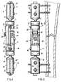
- a dynamic external axial fixator or splint of the inventionis generally indicated by reference numeral 1 and is seen to comprise a central body 2 having two end members 3, 4 each of which is coupled to an associated clamp 5, 6 via ball-joints 7, 8.
- Each clamp 5, 6may be of generally ellipsoidal section, constructed of two opposing halves 5', 5'' and 6', 6'' respectively, and having transversely grooved seats 9, 10 and bolts 11, 12 for securely clamping bolts or screws V which will be understood to have been anchored in the cortical tissue of a fractured bone 0.
- the outer ends of the halves of each clampare hinge-connected to each other, and one half (5', 6') of each clamp is fixedly related to the ball (7,8) of its associated ball-joint connection to the central body 2.
- the body members 3, 4are the first and second of three parts constituting the central body 2. Each of these first two parts 3, 4 has an elongate portion 13 (14) of generally semi-cylindrical section and is integrally formed at one end with a generally cylindrical head 15 (16).
- the semi-cylindrical portions 13, 14are longitudinally lapped, such that the overall appearance of central body 2 is in generally cylindrical conformance with the two heads 15 (16), adjacent to socket components of the respective ball joints 7 (8).
- Transverse bolts 17 (18) through the heads 15 (16)will be understood to enable releasable clamping of the respective ball joints 7 (8) for selective setting of particular angular orientation of the longitudinal axis of each bone screw clamp 5 (6) with respect to the longitudinal axis of central body 2, namely, with respect to the axis determined by the geometric line between ball centers at 7, 8.
- the overall generally cylindrical appearance of the central bodyapplies for the entire range of adjustable overlap of the elongate semi-cylindrical portions 13 (14), as will later become clear.
- the third part of the central bodyis an elongate intermediate member 19 having means determining the longitudinal connection between parts 3, 4 and any relative longitudinal displacement of parts 3, 4 with respect to each other, while also preventing any relative rotation of parts 3, 4 about the axis of the central body, or any significant axial misalignment of either of parts 3, 4 with respect to the axis of the central body.
- the elongate intermediate member 19extends at 20 with constant generally rectangular section for lap of substantially the longitudinal extent of the generally semi-cylindrical portion 14.
- member 19is integrally formed with a transverse head 21.
- the intermediate member 19has a resiliently snubbed and longitudinally guided relation to body part 4, wherein longitudinal guidance derives from the cylindrical shanks of two spaced parallel bolts 26 having relatively deep threaded engagement to tapped threads near the inner ends of deep longitudinal bores in the remote end of the generally semi-cylindrical portion 14 of body part 4.
- longitudinal dimensional notationsare helpful in a description of one of the bolts 26 and the bore to which it is fitted, it being understood that both bolts are identical.
- the dimensional notations a , b , creflect the full effective depth of the bore, wherein the deeply threaded portion is of limited extent b , and wherein, except for the shall depth c of a counterbore, a major fraction a of the bore is cylindrical, for accurate and substantial determination of correct orientation and support of the cylindrical remainder of the shank of the bolt 26, such that the cylindrical shank portion also projects beyond body portion 14, and through an aligned bore and counterbore in the transverse head portion 21 of intermediate body member 19.
- a precision-fitted bushing 30 in each of the bores of head 21is of hardened material and Teflon-lined, for low-friction guidance on the bolt shank.
- the bolt shankterminates at an enlarged head 31 having an exposed transverse slot for screwdriver adjustment.
- First and second sets of dished spring washers 38, 39are located in the respective counterbores in body portions 14 and 21, and the threaded advance of each of the bolts will be understood to selectively determine an axially preloaded and longitudinally neutral position of the intermediate body member 19 with respect of body member 4.
- a transverse slot 36 in each bolt shankwill register with a single transverse pin alignment 28 through both bores in body portion 14, twice for each adjusted full turn of bolts 26, and for a range d of several consecutive turns of bolt adjustment, thus enabling pin 28 to lock a given selected spring preload of the neutral position of body members 4, 19, with respect to each other.
- the intermediate membermay be retained against such transverse displacement as might otherwise jeopardise the fidelity of purely axial displaceability of intermediate member 29 with respect to body member 4. This may be assured by a rod-and-bore engagement similar to what has been described for bolts 26 and their bore-guiding function, but in the form shown it is indicated that a simple transverse link connection at 22 will serve the purpose, in view of the reality that the order of magnitude of maximum displaceability of members 14, 19 is 1.5mm either side of the longitudinally neutral position.
- body part 4is locally recessed at 23, and the corresponding end of intermediate member 19 is locally recessed to define transversely spaced arms for pivotal connection to the upper end of link 22, via a single pin 24; in similar fashion, another transverse pin 25 pivotally connects the lower end of link 22 to body part 4, between confronting sidewalls of the recess 23 in body part 4.
- a degree of looseness or playis tolerable in one or the other of the link (22) connections because the function of link 22 is primarily to assure against any jamming or frictional misalignment of the shank of bolt 26 with respect to its truly axial and resiliently snubbed guidance of the head bushing 30.
- the connected relation of body part 3 to the intermediate memberis one of selected longitudinal adjustment followed by clamping to retain the adjusted position.
- the interior of part 3is recessed to define a generally rectangular shell which derives longitudinal guidance from the generally rectangular section of portion 20 of member 19, all as clearly seen in the cross-section of Fig. 5.
- This guided relationis totally secured by integrally formed longitudinal flanges 31, 32 of body part 3 engaging under bottom edges of portion 20 of intermediate member 19.
- a given fixed longitudinal adjustment of body part 3 to intermediate member 19is achieved via a single bolt 33 and its washer 34, with bolt 33 passing through an elongate slot in the portion 13 of part 3, and with bolt 33 tightly engaged to the threads of a tapped bore 37 in intermediate member 19, as seen in Fig. 4 for the most longitudinally compact adjustment of part 3 on member 19.
- the splintIn the initial phase of applying the described dynamic axial splint to set the segments of a given fracture, it is desirable that the splint shall be a true fixator, i.e. with no provision for dynamic resiliently snubbed displacement of bone fragments.
- a set screw 42frictionally retained by an elastomeric O-ring in a tapped transverse bore in portion 14 of body part 4 may be selectively driven against the underside of portion 20 of intermediate member 19, thereby completely rigidising the spacing between bone-screw clamps 5, 6. Then later, as healing proceeds, release of set screw 42 from engagement with portion 20 will release the parts for dynamic-splint action.
- FIG. 7The fragmentary diagram of Fig. 7 is a detailed showing of a slight modification wherein resiliently snubbed displacements of the described nature can be at least in part implemented via relatively stiff elastomeric bushings 43, 44 which serve the upper and lower pin connections 24, 25 of link 22, it being understood that bushings 43, 44 are bonded both to their respective pins 24, 25 and to their respective bores in link 22, as well as to the pin-mounting bores in portions 14 and 20 respectively, thereby making bushings 43, 44 contribute to the resilient snubbing action via transient torsional stressing of the two elastomeric bushings.
- dished-washer stainless-steel springs and spring setscommercially available from Adolf Schnorr GmbH & Co. KG, of Sindelfingen, Federal Republic of Germany, offer a great variety of spring sizes and of spring constants, to suit the surgeon's prescription for the complete range of patient sizes and requirements.
- bolts 26may be viewed as involving longitudinal guidance via a rod-and-bore engagement, for each of the bolts 26.
- the threaded deep-bore engagementcoupled with the cylindrical shank and its close-fitting support in the bore of portion 14, and over the relatively great axial span a establishes the projecting remainder of the cylindrical part of the shank as a precision reference for axial guidance of the bushed region 30 of the intermediate member 19.
- this bushing 30 and cylindrical-shank engagementas a rod-and-bore engagement, which by reason of the opposed preloading of spring sets at 38, 39 establishes resiliently snubbed and longitudinally guided displaceability of the intermediate body part 19 with respect to one (4) of the central body parts.
- guided displaceabilitynamely, in the order of 1.5mm either side of the neutral or equilibrium position angular displacement of link 22 involves insignificant axial misalignment of the longitudinal axes of the central body parts 3 and 4, particularly if link pins 24, 25 are in a geometric plane that is normal to the axis of body 2, for the equilibrium condition established by spring sets 38, 39.
- the insignificance of such axial misalignmentflows from the fact that the bone-anchoring bolts or screws (V) respectively clamped to different fragments of the fractured bone (O) are themselves subject to small bending deflection when the fractured bone is under longitudinal stress, as when transiently weight-bearing or when a longitudinal adjustment of the spacing between clamps 5, 6 is intentionally made by the surgeon in the course of bone healing.
Landscapes
- Health & Medical Sciences (AREA)
- Orthopedic Medicine & Surgery (AREA)
- Life Sciences & Earth Sciences (AREA)
- Surgery (AREA)
- Public Health (AREA)
- Engineering & Computer Science (AREA)
- Biomedical Technology (AREA)
- Heart & Thoracic Surgery (AREA)
- Medical Informatics (AREA)
- Molecular Biology (AREA)
- Animal Behavior & Ethology (AREA)
- General Health & Medical Sciences (AREA)
- Nuclear Medicine, Radiotherapy & Molecular Imaging (AREA)
- Veterinary Medicine (AREA)
- Surgical Instruments (AREA)
- Materials For Medical Uses (AREA)
- Orthopedics, Nursing, And Contraception (AREA)
- Vessels, Lead-In Wires, Accessory Apparatuses For Cathode-Ray Tubes (AREA)
- Medicines Containing Material From Animals Or Micro-Organisms (AREA)
- Pharmaceuticals Containing Other Organic And Inorganic Compounds (AREA)
- Prostheses (AREA)
- Turbine Rotor Nozzle Sealing (AREA)
- Magnetic Bearings And Hydrostatic Bearings (AREA)
- Saccharide Compounds (AREA)
- Harvesting Machines For Specific Crops (AREA)
Abstract
Description
characterised ii, that said first connectionmeans includes first longitudinal slide means combinedwith resilient snubber means including at least onelink connection, for establishing limited resilientlysnubbed and axial displacement of said first end memberrelative to said intermediate member without anyrelative rotation about said longitudinal axis.
Claims (14)
- External axial fixator, in particular for thedynamic repair of bone fracture, comprising:a pair of clamps (5;6) for securing bone pins(V) implanted in respective stumps of a fractured bone;an elongate central body (2) formed by a firstend member (4) and a second end member (3) defining alongitudinal axis;a ball-joint (7;8) for connecting each end member(3;4) with a respective one of said clamps (5;6);means (17;18) for selectively locking said ball-joints(7;8) thereby fixing said clamps (5;6) atselected angular positions relative to said end members(3;4);a third intermediate member (19) for mutuallycoupling said first (4) and said second (3) end members;first connection means (22;26) for coupling saidthird intermediate member (19) to said first end member(4),;second connection means for stably connectingsaid second end member (3) to said third intermediatemember (19) at fixed longitudinal positions without anyrelative rotation about said longitudinal axis;
characterised in that said first connectionmeans (22,26) includes first longitudinal slide means (26,30)combined with resilient snubber means includingat least one link (22) connection, for establishing limitedresiliently snubbed and axial displacement of saidfirst end member (4) relative to said intermediatemember (19) without any relative rotation about saidlongitudinal axis. - External axial fixator as claimed in claim 1,wherein said link connection comprises at least onetransversely oriented link (22) connecting said second(3) and said third (19) member with such a play toprevent jamming or frictional misalignment thereof.
- External axial fixator as claimed in claim 1,wherein said link connection comprises a pair of links(22) having parallel end pins (24;25) defining ageometric plane that is substantially normal to saidlongitudinal axis.
- External axial fixator as claimed in claim 1,wherein said first (3) and said second (4) end membershave opposite expanded heads (15;16) and adjacentoverlapping portions (13;14) said third intermediatemember (19) being positioned between said overlappingportions (13;14).
- External axial fixator as claimed in claim 1,wherein said third intermediate member (19) has alongitudinal main portion (20) and a transversely offsetend portion (21).
- External axial fixator as claimed in claim 5,wherein said first longitudinal sliding means (26)includes at least one rod-and-bore longitudinal coupling.
- External axial fixator as claimed in claim 6,wherein said longitudinal sliding means (26) includes arod-and-bore engagement extending parallel to saidlongitudinal axis and being transversely spacedtherebetween.
- External axial fixator as claimed in claim 7,wherein said rod-and-bore engagement comprises a firstpair of rods (26) having cylindrical shanks guided inlongitudinal through holes formed in said transverselyoffset end portion (21) of said third intermediate member(19).
- External axial fixator as claimed in claim 8,wherein the ends (26) of said cylindrical shanks areenlarged to provide abutment means for said transverselyend portion (21).
- External axial fixator as claimed in claim 8,wherein said rods (26) have threaded ends remote fromsaid enlarged ends adapted for adjustable threadedengagement in tapped bores formed in said first endmember (4).
- External axial fixator as claimed in claim 10,wherein said second connection means further comprisesresilient means co-acting between said first end member(4) and said third intermediate member (19) forresiliently limiting the relative movement thereof uponapplication of either compressional or tensional forces.
- External axial fixator as claimed in claim 11,wherein said resilient means comprises a stackedplurality of Belleville spring elements (38; 39) guidedby said rods (26) and located between said first endmember (24) and said offset end portion (21) of saidintermediate member (19).
- External axial fixator as claimed in claim 11,wherein said resilient means comprises elastomeric bushes(40;41) inserted between said parallel end pins (24;25) and their connection point in said first end member (4).
- External axial fixator as claimed in claim 1,wherein said second connection means includes secondlongitudinal guide sliding means (35) and a releasablelocking means (37).
Applications Claiming Priority (3)
| Application Number | Priority Date | Filing Date | Title |
|---|---|---|---|
| ITVR920070AIT1258643B (en) | 1992-07-28 | 1992-07-28 | AXIAL DYNAMIC FIXER |
| ITVR920070 | 1992-07-28 | ||
| PCT/EP1993/001825WO1994002078A1 (en) | 1992-07-28 | 1993-07-11 | External axial fixator for osteosynthesis |
Publications (2)
| Publication Number | Publication Date |
|---|---|
| EP0609409A1 EP0609409A1 (en) | 1994-08-10 |
| EP0609409B1true EP0609409B1 (en) | 1998-09-02 |
Family
ID=11427568
Family Applications (1)
| Application Number | Title | Priority Date | Filing Date |
|---|---|---|---|
| EP93915887AExpired - LifetimeEP0609409B1 (en) | 1992-07-28 | 1993-07-11 | External axial fixator for osteosynthesis |
Country Status (22)
| Country | Link |
|---|---|
| US (1) | US5320622A (en) |
| EP (1) | EP0609409B1 (en) |
| JP (1) | JP3297875B2 (en) |
| KR (1) | KR100257734B1 (en) |
| CN (1) | CN1091364C (en) |
| AT (1) | ATE170386T1 (en) |
| AU (1) | AU659389B2 (en) |
| BR (1) | BR9305611A (en) |
| CA (1) | CA2101349C (en) |
| CZ (1) | CZ282378B6 (en) |
| DE (1) | DE69320781T2 (en) |
| ES (1) | ES2119903T3 (en) |
| HU (1) | HU217017B (en) |
| IT (1) | IT1258643B (en) |
| MX (1) | MX9304561A (en) |
| NO (1) | NO308574B1 (en) |
| PL (1) | PL171925B1 (en) |
| SK (1) | SK279818B6 (en) |
| TR (1) | TR27104A (en) |
| TW (1) | TW244333B (en) |
| WO (1) | WO1994002078A1 (en) |
| ZA (1) | ZA935390B (en) |
Cited By (2)
| Publication number | Priority date | Publication date | Assignee | Title |
|---|---|---|---|---|
| US7507240B2 (en) | 2005-03-18 | 2009-03-24 | Ron Anthon Olsen | Adjustable splint for osteosynthesis |
| US7731738B2 (en) | 2005-12-09 | 2010-06-08 | Orthopro, Llc | Cannulated screw |
Families Citing this family (66)
| Publication number | Priority date | Publication date | Assignee | Title |
|---|---|---|---|---|
| DE4231443C1 (en)* | 1992-09-19 | 1993-10-14 | Pennig Dietmar | Osteosynthesis tools |
| US5976134A (en)* | 1995-06-01 | 1999-11-02 | Huebner; Randall J. | External fixator for repairing fractures |
| US6171309B1 (en) | 1995-02-15 | 2001-01-09 | Acumed, Inc. | External fixator for repairing fractures of distal radius and wrist |
| US5624440A (en)* | 1996-01-11 | 1997-04-29 | Huebner; Randall J. | Compact small bone fixator |
| US5658283A (en)* | 1995-02-15 | 1997-08-19 | Huebner; Randall J. | External fixator for repairing fractures |
| US5545162A (en)* | 1995-02-15 | 1996-08-13 | Huebner; Randall J. | External fixator for repairing fractures of distal radius and wrist |
| US5662649A (en)* | 1995-02-15 | 1997-09-02 | Huebner; Randall J. | External fixator for repairing fractures of distal radius and wrist |
| US6162224A (en) | 1995-02-15 | 2000-12-19 | Acumed, Inc. | External fixator for repairing fractures of distal radius and wrist |
| IT1262781B (en)* | 1993-03-15 | 1996-07-04 | Giovanni Faccioli | TOOL AND METHOD FOR THE EXTERNAL REDUCTION OF FRACTURES |
| GB2280608A (en)* | 1993-08-05 | 1995-02-08 | Hi Shear Fasteners Europ Ltd | External bone fixator |
| FR2712481B1 (en)* | 1993-11-18 | 1996-01-12 | Graf Henry | Improvements to flexible inter-vertebral stabilizers. |
| GB9325698D0 (en)* | 1993-12-15 | 1994-02-16 | Richardson James B | Patient-operated orthopedic device |
| USD367531S (en) | 1994-06-27 | 1996-02-27 | Zimmer, Inc. | External fixation clamp |
| IT1268282B1 (en)* | 1994-08-23 | 1997-02-27 | Orthofix Srl | EXTERNAL TROCANTERIC FIXER |
| US5662650A (en) | 1995-05-12 | 1997-09-02 | Electro-Biology, Inc. | Method and apparatus for external fixation of large bones |
| US5743898A (en)* | 1995-05-12 | 1998-04-28 | Electro-Biology, Inc. | Method and apparatus for external fixation of small bones |
| IL114714A (en)* | 1995-07-24 | 1998-12-27 | Hadasit Med Res Service | Orthopedic fixator |
| US5976125A (en)* | 1995-08-29 | 1999-11-02 | The Cleveland Clinic Foundation | External distractor/fixator for the management of fractures and dislocations of interphalangeal joints |
| ES2109178B1 (en)* | 1995-10-26 | 1998-07-16 | Levante Ind Quirurgicas | EXTERNAL BONE FIXING DEVICE FOR HIGHER MEMBER. |
| USD373635S (en) | 1995-11-14 | 1996-09-10 | Zimmer, Inc. | External fixation clamp |
| BR9505235A (en)* | 1995-11-20 | 1997-09-16 | Onofre Gonzalez | External bone stabilization device |
| US5976133A (en)* | 1997-04-23 | 1999-11-02 | Trustees Of Tufts College | External fixator clamp and system |
| US5746741A (en)* | 1996-05-06 | 1998-05-05 | Tufts University | External fixator system |
| IT1289103B1 (en)* | 1996-05-15 | 1998-09-25 | Orthofix Srl | COMPACT EXTERNAL FIXER |
| DE29619711U1 (en) | 1996-11-13 | 1998-03-12 | Synthes AG Chur, Chur, Graubünden | Device for repositioning bone fracture fragments |
| IT1298413B1 (en)* | 1997-05-21 | 2000-01-05 | Orthofix Srl | EXTERNAL MINIFIXER DEVICE FOR SMALL BONE TREATMENT |
| US5944719A (en)* | 1998-11-10 | 1999-08-31 | Millennium Devices, L.L.C. | External fixator |
| US6231528B1 (en) | 1999-01-15 | 2001-05-15 | Jonathan J. Kaufman | Ultrasonic and growth factor bone-therapy: apparatus and method |
| US6245071B1 (en) | 1999-03-10 | 2001-06-12 | Synthes (U.S.A.) | External fixation device for bone |
| US6678562B1 (en) | 2000-01-12 | 2004-01-13 | Amei Technologies Inc. | Combined tissue/bone growth stimulator and external fixation device |
| US6423061B1 (en) | 2000-03-14 | 2002-07-23 | Amei Technologies Inc. | High tibial osteotomy method and apparatus |
| NL1015284C2 (en) | 2000-05-24 | 2001-11-27 | Gerrit Johannes Termaten | Fixation device for orthopedic applications. |
| IL152561A0 (en)* | 2000-05-26 | 2003-05-29 | Orthofix Srl | Disposable external fixation device |
| ES2228444T3 (en) | 2000-05-26 | 2005-04-16 | Orthofix International B.V. | IMPROVED EXTERNAL AXIAL FIXER. |
| KR20020005339A (en)* | 2000-07-06 | 2002-01-17 | 박찬협 | Anatomy conguest and maintenance of bone fracture |
| US6565564B2 (en) | 2000-12-14 | 2003-05-20 | Synthes U.S.A. | Multi-pin clamp and rod attachment |
| EP1238636B1 (en)* | 2001-03-05 | 2006-08-30 | Orthofix International B.V. | External fixation device with identification means |
| US7147640B2 (en) | 2003-03-12 | 2006-12-12 | Acumed Llc | External fixator |
| US7261713B2 (en)* | 2001-10-09 | 2007-08-28 | Synthes (Usa) | Adjustable fixator |
| WO2004026156A1 (en)* | 2002-09-18 | 2004-04-01 | Haci Kutlu | Stable dynamic axial fixator-ii (holyfix) |
| US20060235383A1 (en)* | 2005-03-07 | 2006-10-19 | Shane Hollawell | External fixator |
| US20060229605A1 (en)* | 2005-03-18 | 2006-10-12 | Olsen Ron A | Adjustable splint for osteosynthesis with incrementing assembly for adjustment in predetermined increments |
| US8758343B2 (en) | 2005-04-27 | 2014-06-24 | DePuy Synthes Products, LLC | Bone fixation apparatus |
| US8961516B2 (en) | 2005-05-18 | 2015-02-24 | Sonoma Orthopedic Products, Inc. | Straight intramedullary fracture fixation devices and methods |
| US20060264951A1 (en) | 2005-05-18 | 2006-11-23 | Nelson Charles L | Minimally Invasive Actuable Bone Fixation Devices Having a Retractable Interdigitation Process |
| US9060820B2 (en) | 2005-05-18 | 2015-06-23 | Sonoma Orthopedic Products, Inc. | Segmented intramedullary fracture fixation devices and methods |
| US7881771B2 (en)* | 2005-08-03 | 2011-02-01 | The Hong Kong Polytechnic University | Bone reposition device, method and system |
| US7850696B2 (en)* | 2005-09-28 | 2010-12-14 | Depuy Products, Inc. | Device for facilitating reduction and repair of fractures of the small bones |
| US7749224B2 (en)* | 2005-12-08 | 2010-07-06 | Ebi, Llc | Foot plate fixation |
| WO2008064346A2 (en) | 2006-11-22 | 2008-05-29 | Sonoma Orthopedic Products, Inc. | Fracture fixation device, tools and methods |
| US8277448B2 (en)* | 2007-03-07 | 2012-10-02 | Wright Medical Technology, Inc. | External fixation |
| AU2008318535B2 (en) | 2007-10-31 | 2014-06-19 | Wright Medical Technology, Inc. | Orthopedic device |
| EP2249721B1 (en)* | 2008-02-12 | 2017-07-05 | Texas Scottish Rite Hospital For Children | Fast adjust external fixation connection rod |
| JP2011523889A (en) | 2008-06-10 | 2011-08-25 | ソノマ・オーソペディック・プロダクツ・インコーポレーテッド | Device, tool and method for fixing fractures |
| JP2012504027A (en) | 2008-09-26 | 2012-02-16 | ソノマ・オーソペディック・プロダクツ・インコーポレーテッド | Bone fixation device, tool and method |
| WO2012004798A1 (en)* | 2010-07-07 | 2012-01-12 | Gabriel Waisman | Polyaxial external fixator and method of using the same |
| EP2689730A1 (en)* | 2012-07-24 | 2014-01-29 | WALDEMAR LINK GmbH & Co. KG | Holder for a medical instrument, in particular a surgical instrument |
| ITVR20130013A1 (en)* | 2013-01-21 | 2014-07-22 | Tecres Spa | EXTERNAL FIXING DEVICE FOR THE TREATMENT OF BONE FRACTURES |
| US9301783B2 (en)* | 2013-01-23 | 2016-04-05 | Fixx Orthopedics, LLC | Orthopedic external fixation device |
| US9408635B2 (en) | 2013-03-15 | 2016-08-09 | Wright Medical Technology, Inc. | External fixation |
| EP2967671B1 (en) | 2013-03-15 | 2021-11-17 | Biomet C.V. | Polyaxial pivot housing for external fixation system |
| US9770278B2 (en) | 2014-01-17 | 2017-09-26 | Arthrex, Inc. | Dual tip guide wire |
| US10314618B2 (en)* | 2014-07-25 | 2019-06-11 | The General Hospital Corporation | System and method for an external hip fixator |
| US9814499B2 (en) | 2014-09-30 | 2017-11-14 | Arthrex, Inc. | Intramedullary fracture fixation devices and methods |
| US10874433B2 (en) | 2017-01-30 | 2020-12-29 | Stryker European Holdings I, Llc | Strut attachments for external fixation frame |
| WO2020095217A1 (en)* | 2018-11-06 | 2020-05-14 | Moradi Ali | External orthopedic fixation device |
Family Cites Families (7)
| Publication number | Priority date | Publication date | Assignee | Title |
|---|---|---|---|---|
| US2333033A (en)* | 1943-06-11 | 1943-10-26 | Leslie E Mraz | Bone splint |
| DE3837228A1 (en)* | 1987-11-05 | 1990-05-03 | Robert Dr Sturtzkopf | DEVICE FOR EXTERNAL DETERMINATION OF BONE FRAGMENTS |
| DE3842255C2 (en)* | 1988-12-15 | 1995-08-03 | Leibinger Medizintech | External bone fragment connector |
| DE3936192C2 (en)* | 1989-10-31 | 1996-07-11 | Aesculap Ag | Fixator to fix pieces of bone |
| CH684928A5 (en)* | 1990-12-10 | 1995-02-15 | Jaquet Orthopedie | external fixator. |
| IT1258696B (en)* | 1991-08-02 | 1996-02-27 | Orthofix Srl | AXIAL EXTERNAL FIXER FOR THE COMPOSITION OF BONE FRACTURES |
| DE4139700A1 (en)* | 1991-10-02 | 1993-04-08 | Robert Dr Sturtzkopf | Surgical bone fragment anchor ball joints - has recesses across faces of T-shaped top jaw and vertical bottom jaw, for securing anchorage screws |
- 1992
- 1992-07-28ITITVR920070Apatent/IT1258643B/enactiveIP Right Grant
- 1993
- 1993-04-30USUS08/055,854patent/US5320622A/ennot_activeExpired - Lifetime
- 1993-07-08TWTW082105468Apatent/TW244333B/zhactive
- 1993-07-11ESES93915887Tpatent/ES2119903T3/ennot_activeExpired - Lifetime
- 1993-07-11HUHU9400836Apatent/HU217017B/enunknown
- 1993-07-11CZCZ94890Apatent/CZ282378B6/ennot_activeIP Right Cessation
- 1993-07-11EPEP93915887Apatent/EP0609409B1/ennot_activeExpired - Lifetime
- 1993-07-11BRBR9305611Apatent/BR9305611A/ennot_activeIP Right Cessation
- 1993-07-11ATAT93915887Tpatent/ATE170386T1/enactive
- 1993-07-11AUAU45677/93Apatent/AU659389B2/ennot_activeExpired
- 1993-07-11SKSK339-94Apatent/SK279818B6/ennot_activeIP Right Cessation
- 1993-07-11JPJP50411594Apatent/JP3297875B2/ennot_activeExpired - Lifetime
- 1993-07-11WOPCT/EP1993/001825patent/WO1994002078A1/enactiveIP Right Grant
- 1993-07-11KRKR1019940700994Apatent/KR100257734B1/ennot_activeExpired - Lifetime
- 1993-07-11DEDE69320781Tpatent/DE69320781T2/ennot_activeExpired - Lifetime
- 1993-07-11PLPL93302770Apatent/PL171925B1/enunknown
- 1993-07-19CNCN93108580Apatent/CN1091364C/ennot_activeExpired - Lifetime
- 1993-07-27ZAZA935390Apatent/ZA935390B/enunknown
- 1993-07-27CACA002101349Apatent/CA2101349C/ennot_activeExpired - Lifetime
- 1993-07-28TRTR00665/93Apatent/TR27104A/enunknown
- 1993-07-28MXMX9304561Apatent/MX9304561A/enunknown
- 1994
- 1994-03-24NONO19941072Apatent/NO308574B1/ennot_activeIP Right Cessation
Cited By (4)
| Publication number | Priority date | Publication date | Assignee | Title |
|---|---|---|---|---|
| US7507240B2 (en) | 2005-03-18 | 2009-03-24 | Ron Anthon Olsen | Adjustable splint for osteosynthesis |
| US7575575B2 (en) | 2005-03-18 | 2009-08-18 | Ron Anthon Olsen | Adjustable splint for osteosynthesis with modular components |
| US7588571B2 (en) | 2005-03-18 | 2009-09-15 | Ron Anthon Olsen | Adjustable splint for osteosynthesis with modular joint |
| US7731738B2 (en) | 2005-12-09 | 2010-06-08 | Orthopro, Llc | Cannulated screw |
Also Published As
| Publication number | Publication date |
|---|---|
| WO1994002078A1 (en) | 1994-02-03 |
| HU9400836D0 (en) | 1994-06-28 |
| NO941072L (en) | 1994-03-25 |
| BR9305611A (en) | 1994-10-18 |
| CZ89094A3 (en) | 1994-08-17 |
| NO308574B1 (en) | 2000-10-02 |
| ITVR920070A0 (en) | 1992-07-28 |
| CZ282378B6 (en) | 1997-07-16 |
| HUT68049A (en) | 1995-05-29 |
| NO941072D0 (en) | 1994-03-24 |
| ZA935390B (en) | 1994-02-16 |
| HU217017B (en) | 1999-11-29 |
| CA2101349C (en) | 1996-08-13 |
| AU659389B2 (en) | 1995-05-11 |
| SK279818B6 (en) | 1999-04-13 |
| TW244333B (en) | 1995-04-01 |
| KR100257734B1 (en) | 2000-06-01 |
| US5320622A (en) | 1994-06-14 |
| PL171925B1 (en) | 1997-06-30 |
| CN1082383A (en) | 1994-02-23 |
| SK33994A3 (en) | 1995-01-12 |
| DE69320781D1 (en) | 1998-10-08 |
| ITVR920070A1 (en) | 1994-01-28 |
| CN1091364C (en) | 2002-09-25 |
| TR27104A (en) | 1994-11-08 |
| IT1258643B (en) | 1996-02-27 |
| AU4567793A (en) | 1994-02-14 |
| CA2101349A1 (en) | 1994-01-29 |
| JPH06511411A (en) | 1994-12-22 |
| DE69320781T2 (en) | 1999-03-18 |
| ES2119903T3 (en) | 1998-10-16 |
| PL302770A1 (en) | 1994-08-22 |
| EP0609409A1 (en) | 1994-08-10 |
| JP3297875B2 (en) | 2002-07-02 |
| ATE170386T1 (en) | 1998-09-15 |
| MX9304561A (en) | 1994-03-31 |
Similar Documents
| Publication | Publication Date | Title |
|---|---|---|
| EP0609409B1 (en) | External axial fixator for osteosynthesis | |
| US6171308B1 (en) | Method and apparatus for external fixation of large bones | |
| US6162223A (en) | Dynamic wrist fixation apparatus for early joint motion in distal radius fractures | |
| CA1176529A (en) | Colles fracture fixature device | |
| US4600000A (en) | External fixation system | |
| US5803924A (en) | External fixator | |
| US5704936A (en) | Spinal osteosynthesis device | |
| US4745913A (en) | Apparatus for the stabilization of bone fractures | |
| US5810814A (en) | Bone fixing screw pin | |
| US12161366B2 (en) | External fixation device | |
| US20030109879A1 (en) | External fixator for distal radius fractures | |
| KR20040014202A (en) | Dynamic stabilization device for bones, in particular for vertebrae | |
| US4747400A (en) | External fixation device | |
| US4584995A (en) | External fixation device | |
| WO1995010240A1 (en) | A device for the mutual positioning of bone sections | |
| EP3494911A1 (en) | Dynamic footplate | |
| AU599015B2 (en) | Improved bone fixation system | |
| EP0104044A2 (en) | External fixation system for bone fractures | |
| CA2106333C (en) | External fixator | |
| HU186621B (en) | External fastening for wrist fracture |
Legal Events
| Date | Code | Title | Description |
|---|---|---|---|
| PUAI | Public reference made under article 153(3) epc to a published international application that has entered the european phase | Free format text:ORIGINAL CODE: 0009012 | |
| 17P | Request for examination filed | Effective date:19940603 | |
| AK | Designated contracting states | Kind code of ref document:A1 Designated state(s):AT BE CH DE DK ES FR GB GR IE IT LI LU MC NL PT SE | |
| 17Q | First examination report despatched | Effective date:19950928 | |
| GRAG | Despatch of communication of intention to grant | Free format text:ORIGINAL CODE: EPIDOS AGRA | |
| GRAG | Despatch of communication of intention to grant | Free format text:ORIGINAL CODE: EPIDOS AGRA | |
| GRAH | Despatch of communication of intention to grant a patent | Free format text:ORIGINAL CODE: EPIDOS IGRA | |
| GRAH | Despatch of communication of intention to grant a patent | Free format text:ORIGINAL CODE: EPIDOS IGRA | |
| GRAA | (expected) grant | Free format text:ORIGINAL CODE: 0009210 | |
| AK | Designated contracting states | Kind code of ref document:B1 Designated state(s):AT BE CH DE DK ES FR GB GR IE IT LI LU MC NL PT SE | |
| PG25 | Lapsed in a contracting state [announced via postgrant information from national office to epo] | Ref country code:LI Free format text:LAPSE BECAUSE OF FAILURE TO SUBMIT A TRANSLATION OF THE DESCRIPTION OR TO PAY THE FEE WITHIN THE PRESCRIBED TIME-LIMIT Effective date:19980902 Ref country code:CH Free format text:LAPSE BECAUSE OF FAILURE TO SUBMIT A TRANSLATION OF THE DESCRIPTION OR TO PAY THE FEE WITHIN THE PRESCRIBED TIME-LIMIT Effective date:19980902 Ref country code:BE Free format text:LAPSE BECAUSE OF FAILURE TO SUBMIT A TRANSLATION OF THE DESCRIPTION OR TO PAY THE FEE WITHIN THE PRESCRIBED TIME-LIMIT Effective date:19980902 | |
| REF | Corresponds to: | Ref document number:170386 Country of ref document:AT Date of ref document:19980915 Kind code of ref document:T | |
| REG | Reference to a national code | Ref country code:CH Ref legal event code:EP | |
| REF | Corresponds to: | Ref document number:69320781 Country of ref document:DE Date of ref document:19981008 | |
| REG | Reference to a national code | Ref country code:ES Ref legal event code:FG2A Ref document number:2119903 Country of ref document:ES Kind code of ref document:T3 | |
| ET | Fr: translation filed | ||
| PG25 | Lapsed in a contracting state [announced via postgrant information from national office to epo] | Ref country code:DK Free format text:LAPSE BECAUSE OF FAILURE TO SUBMIT A TRANSLATION OF THE DESCRIPTION OR TO PAY THE FEE WITHIN THE PRESCRIBED TIME-LIMIT Effective date:19981202 | |
| REG | Reference to a national code | Ref country code:IE Ref legal event code:FG4D | |
| REG | Reference to a national code | Ref country code:PT Ref legal event code:SC4A Free format text:AVAILABILITY OF NATIONAL TRANSLATION Effective date:19981202 | |
| REG | Reference to a national code | Ref country code:CH Ref legal event code:PL | |
| PLBE | No opposition filed within time limit | Free format text:ORIGINAL CODE: 0009261 | |
| STAA | Information on the status of an ep patent application or granted ep patent | Free format text:STATUS: NO OPPOSITION FILED WITHIN TIME LIMIT | |
| PG25 | Lapsed in a contracting state [announced via postgrant information from national office to epo] | Ref country code:LU Free format text:LAPSE BECAUSE OF NON-PAYMENT OF DUE FEES Effective date:19990711 Ref country code:IE Free format text:LAPSE BECAUSE OF NON-PAYMENT OF DUE FEES Effective date:19990711 | |
| 26N | No opposition filed | ||
| PG25 | Lapsed in a contracting state [announced via postgrant information from national office to epo] | Ref country code:MC Free format text:LAPSE BECAUSE OF NON-PAYMENT OF DUE FEES Effective date:20000131 | |
| REG | Reference to a national code | Ref country code:IE Ref legal event code:MM4A | |
| REG | Reference to a national code | Ref country code:GB Ref legal event code:IF02 | |
| REG | Reference to a national code | Ref country code:GB Ref legal event code:732E | |
| REG | Reference to a national code | Ref country code:FR Ref legal event code:TP | |
| NLS | Nl: assignments of ep-patents | Owner name:ORTHOFIX INTERNATIONAL B.V. | |
| REG | Reference to a national code | Ref country code:PT Ref legal event code:PC4A Free format text:ORTHOFIX INTERNATIONAL B. V. NL Effective date:20041230 | |
| REG | Reference to a national code | Ref country code:GB Ref legal event code:732E | |
| NLS | Nl: assignments of ep-patents | Owner name:ORTHOFIX S.R.L. Effective date:20070423 | |
| REG | Reference to a national code | Ref country code:ES Ref legal event code:PC2A | |
| REG | Reference to a national code | Ref country code:PT Ref legal event code:PC4A Owner name:ORTHOFIX S.R.L., IT Effective date:20080314 | |
| PGFP | Annual fee paid to national office [announced via postgrant information from national office to epo] | Ref country code:SE Payment date:20120626 Year of fee payment:20 Ref country code:GB Payment date:20120629 Year of fee payment:20 Ref country code:GR Payment date:20120625 Year of fee payment:20 | |
| PGFP | Annual fee paid to national office [announced via postgrant information from national office to epo] | Ref country code:IT Payment date:20120625 Year of fee payment:20 | |
| PGFP | Annual fee paid to national office [announced via postgrant information from national office to epo] | Ref country code:ES Payment date:20120716 Year of fee payment:20 Ref country code:DE Payment date:20120625 Year of fee payment:20 Ref country code:FR Payment date:20120806 Year of fee payment:20 | |
| PGFP | Annual fee paid to national office [announced via postgrant information from national office to epo] | Ref country code:NL Payment date:20120621 Year of fee payment:20 Ref country code:PT Payment date:20120111 Year of fee payment:20 | |
| PGFP | Annual fee paid to national office [announced via postgrant information from national office to epo] | Ref country code:AT Payment date:20120625 Year of fee payment:20 | |
| REG | Reference to a national code | Ref country code:DE Ref legal event code:R071 Ref document number:69320781 Country of ref document:DE | |
| REG | Reference to a national code | Ref country code:NL Ref legal event code:V4 Effective date:20130711 | |
| REG | Reference to a national code | Ref country code:PT Ref legal event code:MM4A Free format text:MAXIMUM VALIDITY LIMIT REACHED Effective date:20130711 | |
| REG | Reference to a national code | Ref country code:GB Ref legal event code:PE20 Expiry date:20130710 | |
| REG | Reference to a national code | Ref country code:SE Ref legal event code:EUG | |
| REG | Reference to a national code | Ref country code:AT Ref legal event code:MK07 Ref document number:170386 Country of ref document:AT Kind code of ref document:T Effective date:20130711 | |
| REG | Reference to a national code | Ref country code:GR Ref legal event code:MA Ref document number:980402632 Country of ref document:GR Effective date:20130712 | |
| PG25 | Lapsed in a contracting state [announced via postgrant information from national office to epo] | Ref country code:PT Free format text:LAPSE BECAUSE OF EXPIRATION OF PROTECTION Effective date:20130718 Ref country code:DE Free format text:LAPSE BECAUSE OF EXPIRATION OF PROTECTION Effective date:20130712 | |
| PG25 | Lapsed in a contracting state [announced via postgrant information from national office to epo] | Ref country code:GB Free format text:LAPSE BECAUSE OF EXPIRATION OF PROTECTION Effective date:20130710 | |
| REG | Reference to a national code | Ref country code:ES Ref legal event code:FD2A Effective date:20140828 | |
| PG25 | Lapsed in a contracting state [announced via postgrant information from national office to epo] | Ref country code:ES Free format text:LAPSE BECAUSE OF EXPIRATION OF PROTECTION Effective date:20130712 |