EP0608969B1 - Encapsulated liquid crystal apparatus with a polymer additive - Google Patents
Encapsulated liquid crystal apparatus with a polymer additiveDownload PDFInfo
- Publication number
- EP0608969B1 EP0608969B1EP94201020AEP94201020AEP0608969B1EP 0608969 B1EP0608969 B1EP 0608969B1EP 94201020 AEP94201020 AEP 94201020AEP 94201020 AEP94201020 AEP 94201020AEP 0608969 B1EP0608969 B1EP 0608969B1
- Authority
- EP
- European Patent Office
- Prior art keywords
- liquid crystal
- crystal material
- medium
- volumes
- latex particles
- Prior art date
- Legal status (The legal status is an assumption and is not a legal conclusion. Google has not performed a legal analysis and makes no representation as to the accuracy of the status listed.)
- Expired - Lifetime
Links
- 239000004973liquid crystal related substanceSubstances0.000titleclaimsdescription155
- 229920000642polymerPolymers0.000titledescription16
- 239000000654additiveSubstances0.000titledescription12
- 230000000996additive effectEffects0.000titledescription12
- 239000000463materialSubstances0.000claimsdescription79
- 239000004816latexSubstances0.000claimsdescription36
- 229920000126latexPolymers0.000claimsdescription36
- 239000000203mixtureSubstances0.000claimsdescription30
- 239000002245particleSubstances0.000claimsdescription29
- 239000000758substrateSubstances0.000claimsdescription24
- 230000005684electric fieldEffects0.000claimsdescription12
- 239000000839emulsionSubstances0.000claimsdescription12
- 230000004888barrier functionEffects0.000claimsdescription10
- 238000000034methodMethods0.000claimsdescription9
- 239000008346aqueous phaseSubstances0.000claimsdescription8
- -1polyethylenesPolymers0.000claimsdescription7
- 230000004044responseEffects0.000claimsdescription7
- 239000000725suspensionSubstances0.000claimsdescription7
- 229920001577copolymerPolymers0.000claimsdescription6
- 239000004988Nematic liquid crystalSubstances0.000claimsdescription4
- 238000010521absorption reactionMethods0.000claimsdescription4
- 238000001035dryingMethods0.000claimsdescription4
- 229920003169water-soluble polymerPolymers0.000claimsdescription4
- 229920006397acrylic thermoplasticPolymers0.000claimsdescription3
- 230000001804emulsifying effectEffects0.000claimsdescription3
- 238000004519manufacturing processMethods0.000claimsdescription3
- 238000002156mixingMethods0.000claimsdescription3
- 229920003229poly(methyl methacrylate)Polymers0.000claimsdescription3
- 229920002635polyurethanePolymers0.000claimsdescription3
- 239000004814polyurethaneSubstances0.000claimsdescription3
- 229920000036polyvinylpyrrolidonePolymers0.000claimsdescription3
- 235000013855polyvinylpyrrolidoneNutrition0.000claimsdescription3
- 239000004698PolyethyleneSubstances0.000claimsdescription2
- 239000004743PolypropyleneSubstances0.000claimsdescription2
- 125000002573ethenylidene groupChemical group[*]=C=C([H])[H]0.000claimsdescription2
- 230000001939inductive effectEffects0.000claimsdescription2
- 229920000573polyethylenePolymers0.000claimsdescription2
- 229920001155polypropylenePolymers0.000claimsdescription2
- 229920001296polysiloxanePolymers0.000claimsdescription2
- 239000001267polyvinylpyrrolidoneSubstances0.000claimsdescription2
- 229920000638styrene acrylonitrilePolymers0.000claimsdescription2
- ISXSCDLOGDJUNJ-UHFFFAOYSA-Ntert-butyl prop-2-enoateChemical compoundCC(C)(C)OC(=O)C=CISXSCDLOGDJUNJ-UHFFFAOYSA-N0.000claims1
- 239000002609mediumSubstances0.000description34
- 239000004094surface-active agentSubstances0.000description23
- 239000002775capsuleSubstances0.000description14
- 239000000975dyeSubstances0.000description8
- 239000012736aqueous mediumSubstances0.000description5
- 239000011148porous materialSubstances0.000description5
- 230000001681protective effectEffects0.000description5
- 239000000126substanceSubstances0.000description5
- 230000000740bleeding effectEffects0.000description4
- 239000000084colloidal systemSubstances0.000description4
- 239000011521glassSubstances0.000description4
- 239000011229interlayerSubstances0.000description4
- XLYOFNOQVPJJNP-UHFFFAOYSA-NwaterSubstancesOXLYOFNOQVPJJNP-UHFFFAOYSA-N0.000description4
- 238000010276constructionMethods0.000description3
- 238000003475laminationMethods0.000description3
- 229920003023plasticPolymers0.000description3
- 239000004033plasticSubstances0.000description3
- 229920002037poly(vinyl butyral) polymerPolymers0.000description3
- 239000004990Smectic liquid crystalSubstances0.000description2
- 230000001070adhesive effectEffects0.000description2
- 238000013019agitationMethods0.000description2
- 230000008901benefitEffects0.000description2
- 230000005540biological transmissionEffects0.000description2
- 230000015572biosynthetic processEffects0.000description2
- 230000003098cholesteric effectEffects0.000description2
- 239000011248coating agentSubstances0.000description2
- 238000000576coating methodMethods0.000description2
- 239000003431cross linking reagentSubstances0.000description2
- 230000001419dependent effectEffects0.000description2
- 230000000694effectsEffects0.000description2
- 238000004945emulsificationMethods0.000description2
- 239000005038ethylene vinyl acetateSubstances0.000description2
- 238000009472formulationMethods0.000description2
- 125000000524functional groupChemical group0.000description2
- 239000007788liquidSubstances0.000description2
- 229920006113non-polar polymerPolymers0.000description2
- 230000003287optical effectEffects0.000description2
- 229920000728polyesterPolymers0.000description2
- 238000007789sealingMethods0.000description2
- 239000007787solidSubstances0.000description2
- 230000000007visual effectEffects0.000description2
- FHNINJWBTRXEBC-UHFFFAOYSA-NSudan IIIChemical compoundOC1=CC=C2C=CC=CC2=C1N=NC(C=C1)=CC=C1N=NC1=CC=CC=C1FHNINJWBTRXEBC-UHFFFAOYSA-N0.000description1
- YCUVUDODLRLVIC-UHFFFAOYSA-NSudan black BChemical compoundC1=CC(=C23)NC(C)(C)NC2=CC=CC3=C1N=NC(C1=CC=CC=C11)=CC=C1N=NC1=CC=CC=C1YCUVUDODLRLVIC-UHFFFAOYSA-N0.000description1
- 239000000853adhesiveSubstances0.000description1
- 239000012790adhesive layerSubstances0.000description1
- 230000002411adverseEffects0.000description1
- 239000007864aqueous solutionSubstances0.000description1
- DQXBYHZEEUGOBF-UHFFFAOYSA-Nbut-3-enoic acid;etheneChemical compoundC=C.OC(=O)CC=CDQXBYHZEEUGOBF-UHFFFAOYSA-N0.000description1
- 230000008859changeEffects0.000description1
- 150000001875compoundsChemical class0.000description1
- 230000003247decreasing effectEffects0.000description1
- 230000007547defectEffects0.000description1
- 239000006185dispersionSubstances0.000description1
- 230000007613environmental effectEffects0.000description1
- RBTKNAXYKSUFRK-UHFFFAOYSA-Nheliogen blueChemical compound[Cu].[N-]1C2=C(C=CC=C3)C3=C1N=C([N-]1)C3=CC=CC=C3C1=NC([N-]1)=C(C=CC=C3)C3=C1N=C([N-]1)C3=CC=CC=C3C1=N2RBTKNAXYKSUFRK-UHFFFAOYSA-N0.000description1
- AMGQUBHHOARCQH-UHFFFAOYSA-Nindium;oxotinChemical compound[In].[Sn]=OAMGQUBHHOARCQH-UHFFFAOYSA-N0.000description1
- 239000004615ingredientSubstances0.000description1
- 238000010030laminatingMethods0.000description1
- 239000010410layerSubstances0.000description1
- 230000031700light absorptionEffects0.000description1
- 238000011068loading methodMethods0.000description1
- 239000000178monomerSubstances0.000description1
- 239000007764o/w emulsionSubstances0.000description1
- 239000003973paintSubstances0.000description1
- 239000012071phaseSubstances0.000description1
- 230000000704physical effectEffects0.000description1
- 229920001200poly(ethylene-vinyl acetate)Polymers0.000description1
- 229920002239polyacrylonitrilePolymers0.000description1
- 230000008569processEffects0.000description1
- 230000005855radiationEffects0.000description1
- 238000009877renderingMethods0.000description1
- 229940099373sudan iiiDrugs0.000description1
- 229920001169thermoplasticPolymers0.000description1
- 239000004416thermosoftening plasticSubstances0.000description1
- 238000009834vaporizationMethods0.000description1
- 230000008016vaporizationEffects0.000description1
Images
Classifications
- C—CHEMISTRY; METALLURGY
- C09—DYES; PAINTS; POLISHES; NATURAL RESINS; ADHESIVES; COMPOSITIONS NOT OTHERWISE PROVIDED FOR; APPLICATIONS OF MATERIALS NOT OTHERWISE PROVIDED FOR
- C09K—MATERIALS FOR MISCELLANEOUS APPLICATIONS, NOT PROVIDED FOR ELSEWHERE
- C09K19/00—Liquid crystal materials
- C09K19/52—Liquid crystal materials characterised by components which are not liquid crystals, e.g. additives with special physical aspect: solvents, solid particles
- C09K19/54—Additives having no specific mesophase characterised by their chemical composition
- C09K19/542—Macromolecular compounds
- C09K19/544—Macromolecular compounds as dispersing or encapsulating medium around the liquid crystal
- C—CHEMISTRY; METALLURGY
- C09—DYES; PAINTS; POLISHES; NATURAL RESINS; ADHESIVES; COMPOSITIONS NOT OTHERWISE PROVIDED FOR; APPLICATIONS OF MATERIALS NOT OTHERWISE PROVIDED FOR
- C09K—MATERIALS FOR MISCELLANEOUS APPLICATIONS, NOT PROVIDED FOR ELSEWHERE
- C09K2323/00—Functional layers of liquid crystal optical display excluding electroactive liquid crystal layer characterised by chemical composition
- C09K2323/05—Bonding or intermediate layer characterised by chemical composition, e.g. sealant or spacer
- C09K2323/057—Ester polymer, e.g. polycarbonate, polyacrylate or polyester
- Y—GENERAL TAGGING OF NEW TECHNOLOGICAL DEVELOPMENTS; GENERAL TAGGING OF CROSS-SECTIONAL TECHNOLOGIES SPANNING OVER SEVERAL SECTIONS OF THE IPC; TECHNICAL SUBJECTS COVERED BY FORMER USPC CROSS-REFERENCE ART COLLECTIONS [XRACs] AND DIGESTS
- Y10—TECHNICAL SUBJECTS COVERED BY FORMER USPC
- Y10S—TECHNICAL SUBJECTS COVERED BY FORMER USPC CROSS-REFERENCE ART COLLECTIONS [XRACs] AND DIGESTS
- Y10S516/00—Colloid systems and wetting agents; subcombinations thereof; processes of
- Y10S516/01—Wetting, emulsifying, dispersing, or stabilizing agents
- Y—GENERAL TAGGING OF NEW TECHNOLOGICAL DEVELOPMENTS; GENERAL TAGGING OF CROSS-SECTIONAL TECHNOLOGIES SPANNING OVER SEVERAL SECTIONS OF THE IPC; TECHNICAL SUBJECTS COVERED BY FORMER USPC CROSS-REFERENCE ART COLLECTIONS [XRACs] AND DIGESTS
- Y10—TECHNICAL SUBJECTS COVERED BY FORMER USPC
- Y10T—TECHNICAL SUBJECTS COVERED BY FORMER US CLASSIFICATION
- Y10T428/00—Stock material or miscellaneous articles
- Y10T428/29—Coated or structually defined flake, particle, cell, strand, strand portion, rod, filament, macroscopic fiber or mass thereof
- Y10T428/2982—Particulate matter [e.g., sphere, flake, etc.]
- Y10T428/2984—Microcapsule with fluid core [includes liposome]
- Y10T428/2985—Solid-walled microcapsule from synthetic polymer
Definitions
- the present inventionrelates generally to liquid crystal, and more particularly to a nematic curvilinear aligned phase (NCAP) liquid crystal film incorporating a polymer additive for forming a protective wall within the containment medium.
- NCAPnematic curvilinear aligned phase
- Liquid crystalsare used in a wide variety of devices, including visual display devices.
- the property of liquid crystals that enables them to be used, for example in visual displays,is the ability of liquid crystals to transmit light on the one hand and to scatter light and/or absorb it (especially when combined with an appropriate dye) on the other, depending on whether the liquid crystals are in a relatively free, that is de-energized or field-off state, or in a relatively aligned, that is energized or field-on state.
- An electric field selectively applied across the liquid crystalsmay be used to switch between the field-off and field-on states.
- liquid crystal materialwhich is operationally nematic.
- operationally nematicis meant that, in the absence of external fields, structural distortion of the liquid crystal is dominated by the orientation of the liquid crystal at its boundaries rather than by bulk effects, such as very strong twists (as in cholesteric material) or layering (as in smectic material).
- a liquid crystal material including chiral ingredientswhich induce a tendency to twist but which cannot overcome the effects of the boundary alignment of the liquid crystal material would be considered to be operationally nematic.
- NCAP liquid crystal and devices using NCAP liquid crystalare also described in the above-identified U.S. Patent No. 4,435,047.
- a functional NCAP liquid crystal devicemay consist of NCAP liquid crystal sandwiched between two electrode-coated substrates.
- the substratesmay be polyester (PET) coated with indium tin oxide to form electrodes.
- the encapsulated NCAP or filmmay comprise a containment medium containing plural volumes of operationally nematic liquid crystals.
- the plural volumesmay be discrete or interconnected cavities or capsules.
- the interconnecting channels or passagewaysmay also contain liquid crystal material. This structure is described in more detail in U.S. Patent No. 4,707,080.
- a voltage sourcemay be connected between the electrodes to selectively apply an electric field across the liquid crystal material.
- the liquid crystal materialwill scatter and/or absorb light in the field-off state and transmit light in the field-on state.
- the liquid crystal material or filmwill be clear in the field-on state and cloudy or hazy (in the absence of a pleochroic dye) in the field-off state.
- the NCAP filmmay be used in the construction of windows and the like. Such apparatus are described in U.S. Patent No. 4,749,261.
- a windowmay be fabricated by laminating the electrode-coated substrate that supports the NCAP film to a window surface, for example glass or a sheet plastic, by means of an optically-transparent adhesive or interlayer.
- a window surfacefor example glass or a sheet plastic
- an optically-transparent adhesive or interlayeris polyvinylbutyral (PVB).
- PVBpolyvinylbutyral
- EVAethylenevinyl acetate
- polyurethanepolyurethane
- PVB and EVAare thermoplastic film adhesives as opposed to liquids. As such, they offer convenient handling and processing. These interlayer materials also can provide safety glazing and impact resistance properties. Other advantages include: clearness, low haze, environmental stability, and ultra-violet light absorption.
- the lamination of a NCAP film substrate to a glass or plastic surfacemay, however, adversely affect the electro-optical performance of the film. That is, portions of the film may no longer scatter light as effectively in the field-off state. Thus, those portions would transmit light more specularly and be clearer in the field-off state. This is thought to be caused by mechanical stresses applied to the NCAP film during the lamination process. Such mechanical stresses are believed to cause a change in the shape and/or structure of the cavities, capsules or interconnecting passageways. Additionally, such stresses may cause a flow of liquid crystal, for example to the film's surface, through the passageways or pores in the containment medium. This phenomenon, called “stress clearing", degrades the film's electro-optical performance.
- an object of embodiments of the present inventionis to provide an encapsulated liquid crystal material that is more resistant to mechanical stress.
- a more specific object of embodiments of the present inventionis to provide a NCAP film incorporating a polymer additive that forms a wall within volumes of the containment medium containing liquid crystal material.
- the present inventionprovides a liquid crystal apparatus comprising a latex containment medium, a liquid crystal material dispersed in plural volumes in said medium, said medium inducing a generally distorted alignment of said liquid crystal material which in response to said alignment at least one of scatters and absorbs light and which in response to a prescribed input reduces the amount of such scattering or absorption, and wherein passageways extend from said volumes, characterised by barrier means formed at least substantially between said liquid crystal material and said medium to impede the flow of said liquid crystal material from said plural volumes to preserve the integrity of said volumes and forming a wall in at least some of said passageways to impede the flow of said liquid crystal material therethrough, said barrier means not being formed from polyvinylpyrrolidone.
- the barrier means and the liquid crystal materialhave solubility parameters that differ by at least two Hildebrand units.
- the liquid crystal materialcan be an operationally nematic liquid crystal having positive dielectric anisotropy. This liquid crystal material is contained in plural volumes in the containment medium.
- Figure 1is a schematic view illustrating a NCAP liquid crystal apparatus.
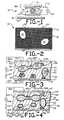
- Figure 2is a schematic view illustrating a mixture of an aqueous medium with a suspension of latex particles prior to drying.
- Figure 3is a schematic view illustrating a device formed from the mixture illustrated in Figure 2 in the absence of an electric field.
- Figure 4is a schematic view illustrating a device formed from the mixture illustrated in Figure 2 in the presence of an electric field.
- Figure 1shows a NCAP liquid crystal apparatus indicated generally by reference numeral 10 and disclosed in U.S. Patent No. 4,435,047.
- the apparatusincludes a NCAP liquid crystal 11 supported on a substrate 12 having an electrode 13 located thereon.
- the apparatusalso comprises a second electrode 14 mounted on substrate 15.
- substrate 12 and electrode 13may also be referred to as electrode-coated substrate 18, and, similarly, substrate 15 and electrode 14 may be referred to as electrode-coated substrate 18A.
- the NCAP liquid crystal 11includes a liquid crystal material 20 more or less contained within the confines of the interior volume 21 of a capsule 22.
- a voltagemay be applied to electrode-coated substrates 18 and 18A, and hence across liquid crystal 11 from an AC or DC voltage source 16.
- Voltage source 16is connected to electrode-coated substrates 18 and 18A by electrical leads and through selectively closeable switch 17.
- switch 17When switch 17 is closed, a voltage is applied across electrode-coated substrates 18 and 18A causing the liquid crystal molecules to align with the field thereby becoming optically transmissive.
- switch 17When switch 17 is open and no voltage is applied, the liquid crystal scatters and/or absorbs light.
- Mounting substrates 12 and 15, and electrodes 13 and 14can be optically transparent so that the liquid crystal apparatus 10 is capable of controlling the transmission of light therethrough in response to an electric field applied across electrode-coated substrates 18 and 18A.
- electrode coated substrate 18may be optically reflective or may have thereon an optically reflective coating so that reflection by such reflective coating of incident light will be a function of whether there is an electric field applied across the liquid crystal 11.
- the mounting substrates and electrodesare optically transmissive.
- Figure 2illustrates a layer of an undried mixture 19 obtained when liquid crystal material 20 is combined in an aqueous medium with a suspension of latex particles 24.
- Figure 2also schematically illustrates a polymer additive 30 added in mixture 19 to coalesce about liquid crystal particles 20 and latex particles 24. Additionally, this protective colloid polymer may be dispersed in the aqueous medium. As will be discussed, the polymer additive serves to maintain the integrity of the liquid crystal volumes as the mixture dries to form the NCAP film. That is, the polymer additive forms a barrier to the flow of liquid crystal material from one capsule to another, from a capsule to the film's surface and/or from a capsule into the film's containment medium.
- liquid crystal 20 in mixture 19there is a wide variety of materials from which liquid crystal 20 in mixture 19 may be chosen. This degree of choice also exists within the nematic category of liquid crystal. As a consequence and as discussed heretofore, this invention is not limited to any category of liquid crystal or to any specific material.
- liquid crystal and latex particleswill depend upon a variety of physical properties for each material, for example the solubility of the liquid crystal material in the latex particles. In general, the solubility of the liquid crystal material in the latex particles should be less than about 20% of the initial volume of liquid crystal material. If the liquid crystal is relatively insoluble in the latex, a dispersion of discrete liquid crystal particles in the latex medium may be formed. Such compositions are highly efficient in scattering and/or absorbing light in the field-off state but are optically transmissive in the field-on state.
- the units of ⁇are (cal/cm 3 ) but for convenience are designated as the Hildebrand unit (H).
- the solubility parameters of the latex polymersrange from 6H to 16H.
- the solubility parameter of typical liquid crystal materialranges from 12H to 13H although the range may extend from 10H to 15H.
- nonpolar liquidssuch as the liquid crystal material used in liquid crystal display devices, are miscible with nonpolar polymers when their solubility parameters differ by about 2H units or less. If the liquid crystal material has a solubility parameter of about 12H, it can be determined that latex particles with solubility parameters below 10H or greater than 14H should be capable of forming latex entrapped NCAP liquid crystal.
- groups of latex polymers with solubility parameters below 10Hinclude: polyethylenes, polypropylenes, polyurethanes, polyacrylics, and polysiloxanes.
- An example of a latex polymer with a solubility parameter greater than 14His polyacrylonitrile, which has a solubility parameter of 15.4H.
- Groups of latex copolymers with solubility parameters less than about 10Hinclude: methacrylate-acrylonitriles, urethane-acrylics, acrylate-acrylonitriles, styrene-acrylonitriles, and vinylidene chloride-acrylonitriles.
- These groups of latex polymers and copolymersinclude the unsubstituted polymer and copolymer as well as the wide variety of polymers and copolymers obtained by substituting various functional groups in the monomers used to make such polymers and copolymers.
- latex NCAP liquid crystal compositionsmay be made even if the theoretical solubility parameters of the liquid crystal and latex particles are close to each other.
- the theoretical solubility parameters of liquid crystal and latex particlesmay be used to select components for the composition when the solubility parameters differ by more than 2H units. If the difference in solubility parameters is less than 2H units, the choice of liquid crystal and latex particles may be based on an empirical determination that the liquid crystal and latex particles chosen can produce a functional composition.
- the choice of a surfactant which may be necessary to generate an emulsion of liquid crystal particles in an aqueous phaseis an important consideration, since the liquid crystal particle size may be controlled by the amount and chemical characteristics of the surfactant.
- the particle sizedetermines the electro-optical properties of an apparatus.
- the amount of surfactant used for emulsifying the liquid crystal materialshould be the minimal amount needed to stabilize the liquid crystal emulsion and to control the liquid crystal particle size. This is because an excessive amount of surfactant may cause excessive depression of the clearing point temperature of the liquid crystal, rendering a particular composition useless for its intended purpose.
- HLB coefficientlypophile-hydrophile balance coefficient
- the HLB coefficientreflects the solubility of a substance in oil or water.
- An HLB coefficient less than about 9indicates that the surfactant has lypophilic characteristics; i . e ., it interacts with the liquid crystal.
- An HLB coefficient greater than about 12indicates that the surfactant has hydrophilic characteristics, i . e ., it has an affinity for water.
- surfactantswith an HLB coefficient between 12 and 17 may be required to emulsify a liquid crystal material in an aqueous phase.
- the optimal HLB coefficient of the surfactantmay be determined experimentally by observing the extent and stability of a liquid crystal emulsion in an aqueous phase as a function of a surfactant's HLB coefficient.
- the HLB coefficientis, however, only one parameter which may be considered in choosing an appropriate surfactant.
- the amount of surfactant needed for emulsificationmay be related to the chemical characteristics of the surfactant. Since it is desirable to minimize the amount of surfactant, surfactants from different chemical classes with HLB coefficients close to the experimentally-determined optimal HLB coefficient may be selected to determine for each chemical class the minimal amount of surfactant needed. The preferred surfactant may then be chosen based on these results.
- the mixturefurther includes a protective colloid polymer 30 that forms walls 50 in the dried composition.
- a protective colloid polymer 30that forms walls 50 in the dried composition.
- volumes of liquid crystal 20are dispersed throughout containment medium 28.
- the liquid crystal 20may be located in capsules 23, and in passageways or channels 35 and 37.
- the capsules 23may be interconnected by passageways 35. Such interconnecting passages occur relatively randomly. Some capsules may not be interconnected to others, while some may be interconnected by one or more passages 35 to one or more other capsules.
- the interconnectionscan be continuous or substantially continuous, or may be discontinuous.
- the capsulesmay also be connected by pores or passageways 37 to the surface 39 of the film.
- Protective wall 50is formed in the volumes of liquid crystal material dispersed throughout containment medium 28.
- the wall 50is formed along the outer boundaries of capsules 23 at the interface with the containment medium, and along passageways 35 and 37. As such, the wall forms a barrier between containment medium 28 and liquid crystal 20. It is also believed that inner wall 50 is formed in passageways 35 to block the flow of liquid crystal 20 from one capsule to another. Similarly, wall 50 may exist across passageway 37 to prevent the flow of liquid crystal 20 to surface 39. In this manner, the integrity of the liquid crystal volumes as they exist in the aqueous medium are preserved in the dried film.
- This inner wall or interlayereffectively provides a shell around the liquid crystal material and a barrier to flow, e , g ., in the passageways.
- the NCAP filmhas improved resistance to mechanical stresses, which may be imposed thereon, for example, when the film is used in the construction of windows, displays, or other electro-optical devices. Accordingly, the above-discussed "stress clearing" problem is substantially reduced if not, in fact, eliminated.
- wall 50may seal pores 37 to reduce, if not prevent entirely, the bleeding or flow of liquid crystal to film surface 39, during drying of the mixture prior to lamination to an electrode-coated substrate.
- sealing pores 37permit higher loadings of liquid crystal (the amount of liquid crystal per unit of containment medium material), without bleeding, resulting in a better optical response, i . e . improved contrast between the on and off states.
- optical defects caused by "free" liquid crystal at the film surfacemay be substantially reduced or eliminated by sealing pores 37. Preventing such bleeding also provides a better surface for adhering the electrode-coated substrate.
- Latexis insoluble in water, and the additive that forms inner wall 50 is water soluble. As mentioned, this water-soluble polymer coalesces around the liquid crystal and latex particles during formation of the composition.
- the additive or wall-forming material 30should not react with the liquid crystal material; that is, it should not react with known functional groups of the liquid crystal material. Additionally, as in the case of the liquid crystal and latex, the liquid crystal should be relatively insoluble in additive 30.
- solubility parameter of a typical liquid crystal materialranges from 12H to 13H, and at temperatures below about 50°C, liquid crystal materials are miscible with nonpolar polymers when their solubility parameters differ by about 2H units or less.
- solubility parameteras a guide, it is believed that additive 30 should have a solubility parameter either below 10H or above 15H.
- the indices of refraction of the liquid crystal and the containment medium materialare preferably matched to maximize contrast between the field-on and field-off states. If the index of refraction of the containment medium is not closely matched to the ordinary index of refraction of the liquid crystal material, incident radiation may be refracted in the field-on state resulting in decreased transmission due to scattering and/or absorption.
- the closeness of the index matchingwill be dependent on the desired degree of contrast and transparency of the device, but the ordinary index of refraction of the liquid crystal and the index of refraction of the containment medium will preferably differ by no more than 0.07, more preferably 0.01, especially .001.
- the index of refraction of the wall material 50should be approximately the same as the containment medium.
- the inner wallmay be made relatively thin in comparison to the wavelength of light so that in the field-on state there is no excessive refraction of light at the boundaries of the containment medium, the inner wall and the liquid crystal material.
- the thickness of inner wall 50may be less than about 10 -7 m (1,000 angstroms). Thus, if inner wall is made thin enough, its index of refraction may not be important in maximizing contrast.
- the NCAP filmshould have a containment medium and an inner wall which each have a dielectric constant that is greater than the dielectric coefficient of the liquid crystal in the absence of an electric field.
- the dielectric constants of the containment medium and the inner wallare about equal. The efficiency of the electro-optical performance is enhanced when the liquid crystal material has a positive dielectric anisotropy, and its ordinary dielectric coefficient is less than the dielectric constants of the containment medium and the inner wall.
- the extraordinary dielectric coefficient of the liquid crystalshould be matched as closely as possible to the dielectric constants of the containment medium and the inner wall. However, it is more important that the extraordinary dielectric coefficient of the liquid crystal match the dielectric constant of the containment medium.
- the containment medium and the inner wallshould have a relatively large impedance to ensure that a maximum voltage drop occurs across the liquid crystal, resulting in maximum electro-optical efficiency.
- the compositionshould have a demonstrated resistance to moisture. That is, the contrast of an apparatus constructed as herein before described should not degrade when exposed to a high humidity environment, and there should be very little increase in moisture dependent leakage current. To prevent moisture from being a problem, it is preferred that the amount of PVP not exceed about 5.0% of the weight of the containment medium.
- mixture 19may be made according to the following methods.
- the liquid crystal and additive 30 that forms wall 50may be first emulsified by agitating the liquid crystal in an aqueous solution.
- the amount of liquid crystalranges from 30% to 60% of the total emulsion volume.
- the wall-forming material 50may be present in a range from 1.0% to 20.0% of the total weight of the resulting solid.
- Surfactantsmay be employed to generate and maintain the liquid crystal emulsion.
- the amount of surfactantmay be between 0.1 wt. % to 6.0 wt. %, preferably less than 3 wt. % of the total wet emulsion.
- a surfactant which may be usedis IGEPAL CO-610 (Trade Mark) (available through GAF Corp., New York, New York).
- Agitation to form the emulsionmay be performed in a colloid mill, a high speed disperser or other devices known to those skilled in the art.
- the agitationis terminated when the emulsified liquid crystal/protective colloid particles have a diameter from 1 micron to 10 microns, and preferably 1-5 microns.
- This emulsion and 1-3 volumes of a suspension of latex particleswhich range in size from 0.01 microns to 2.0 microns and comprising 20% to 60% of the suspension volume, may then be slowly combined with constant mixing.
- a cross-linking agentmay be added to further improve the tensile strength and the moisture resistance of the composition.
- the cross-linking agent utilizedis specific to the latex polymer.
- the mixturemay be layered onto an electrode-coated substrate 18 (see Figures 3 and 4) and dried to generate a solid medium 28 with liquid crystal 20 dispersed therein in volumes and wall 50 formed in such volumes.
- An alternate but preferred methodis to simply add all of the components together, and emulsify the liquid crystal directly into the aqueous medium.
- This methodhas the advantage of ease in processing, but some of the control over particle size may be sacrificed.
- the wall-forming material 50may be added to a mixture comprising the latex particles, the liquid crystal material and the surfactant. This is preferred if the amount of wall-forming material added causes the viscosity of the mixture to be too high.
- all the componentsmay be added at the same time and then mixed.
- Pleochroic dyessuch as Oil Blue N, Sudan black, Sudan III and Sudan II (all available through Aldrich Chemical Co., Milwaukee, WI) may also be employed.
- such dyesare dissolved in the liquid crystal prior to emulsifying the liquid crystal in an aqueous phase.
- Such dyesare typically 0.5 wt. % to 6 wt. % of the liquid crystal material.
- Isotropic dyessuch as copper phthalocyanine may also be used in quantities ranging from 0.5 wt. % to 6 wt. % of the liquid crystal material.
- Inner wall 50is particularly effective in isolating such dyes from the containment medium so that the dyes do not "bleed" into the containment medium.
- electrode-coated substrates 18 and 18Amay contact the opposite faces of the NCAP film, and be connected by leads 25 and 25A, respectively, to voltage source 26.
- switch 27When switch 27 is open no voltage is applied to the film and the molecules of liquid crystal, depicted as dashed lines, are shown to be distorted by capsules or cavities 23 and passageways 35 and 37 containing the liquid crystal. An array of such molecules will scatter and/or absorb light from all directions since the liquid crystal material as a whole has a random orientation.
- the NCAP liquid crystal film of the present inventionis extremely resistant to mechanical stress and has enhanced properties that prevent "bleeding" of the liquid crystal. As such, its electro-optical performance and durability are enhanced. The longevity of a liquid crystal apparatus is also improved when laminated to a glass or sheet plastic surface or substrate as may occur in the fabrication of a window.
Landscapes
- Chemical & Material Sciences (AREA)
- Crystallography & Structural Chemistry (AREA)
- Engineering & Computer Science (AREA)
- Materials Engineering (AREA)
- Organic Chemistry (AREA)
- Liquid Crystal (AREA)
Description
- The present invention relates generally to liquidcrystal, and more particularly to a nematiccurvilinear aligned phase (NCAP) liquid crystal filmincorporating a polymer additive for forming aprotective wall within the containment medium.
- Liquid crystals are used in a wide variety ofdevices, including visual display devices. Theproperty of liquid crystals that enables them to beused, for example in visual displays, is the abilityof liquid crystals to transmit light on the one handand to scatter light and/or absorb it (especially whencombined with an appropriate dye) on the other,depending on whether the liquid crystals are in arelatively free, that is de-energized or field-offstate, or in a relatively aligned, that is energizedor field-on state. An electric field selectivelyapplied across the liquid crystals may be used toswitch between the field-off and field-on states.
- There are three categories of liquid crystalmaterial, namely cholesteric, nematic and smectic. Thepresent invention relates in the preferred embodimentdescribed hereinafter to the use of liquid crystalmaterial which is operationally nematic. By"operationally nematic" is meant that, in the absenceof external fields, structural distortion of theliquid crystal is dominated by the orientation of theliquid crystal at its boundaries rather than by bulkeffects, such as very strong twists (as in cholestericmaterial) or layering (as in smectic material). Thus,for example, a liquid crystal material includingchiral ingredients which induce a tendency to twistbut which cannot overcome the effects of the boundaryalignment of the liquid crystal material would beconsidered to be operationally nematic.
- A more detailed explanation of operationally nematic liquid crystal material is provided in U.S.Patent No 4,616,903.
- Reference may also be made to U.S. Patent4,435,047.
- NCAP liquid crystal and devices using NCAP liquidcrystal are also described in the above-identifiedU.S. Patent No. 4,435,047. A functional NCAP liquidcrystal device may consist of NCAP liquid crystalsandwiched between two electrode-coated substrates.The substrates may be polyester (PET) coated withindium tin oxide to form electrodes. The encapsulatedNCAP or film may comprise a containment mediumcontaining plural volumes of operationally nematicliquid crystals. The plural volumes may be discreteor interconnected cavities or capsules. Theinterconnecting channels or passageways may alsocontain liquid crystal material. This structure isdescribed in more detail in U.S. Patent No. 4,707,080.
- A voltage source may be connected between theelectrodes to selectively apply an electric fieldacross the liquid crystal material. As is known, theliquid crystal material will scatter and/or absorblight in the field-off state and transmit light in thefield-on state. Thus, the liquid crystal material orfilm will be clear in the field-on state and cloudy orhazy (in the absence of a pleochroic dye) in thefield-off state.
- The NCAP film may be used in the construction ofwindows and the like. Such apparatus are described inU.S. Patent No. 4,749,261.
- A window may be fabricated by laminating theelectrode-coated substrate that supports the NCAP filmto a window surface, for example glass or a sheetplastic, by means of an optically-transparent adhesiveor interlayer. One of the more commonly used glass interlayers is polyvinylbutyral (PVB). Others areethylenevinyl acetate (EVA) and polyurethane.
- PVB and EVA are thermoplastic film adhesives asopposed to liquids. As such, they offer convenienthandling and processing. These interlayer materialsalso can provide safety glazing and impact resistanceproperties. Other advantages include: clearness, lowhaze, environmental stability, and ultra-violet lightabsorption.
- The lamination of a NCAP film substrate to aglass or plastic surface may, however, adverselyaffect the electro-optical performance of the film.That is, portions of the film may no longer scatterlight as effectively in the field-off state. Thus,those portions would transmit light more specularlyand be clearer in the field-off state. This isthought to be caused by mechanical stresses applied tothe NCAP film during the lamination process. Suchmechanical stresses are believed to cause a change inthe shape and/or structure of the cavities, capsulesor interconnecting passageways. Additionally, suchstresses may cause a flow of liquid crystal, forexample to the film's surface, through the passagewaysor pores in the containment medium. This phenomenon,called "stress clearing", degrades the film's electro-opticalperformance.
- Accordingly, an object of embodiments of thepresent invention is to provide an encapsulated liquidcrystal material that is more resistant to mechanicalstress.
- A more specific object of embodiments of thepresent invention is to provide a NCAP filmincorporating a polymer additive that forms a wallwithin volumes of the containment medium containingliquid crystal material.
- The present invention provides a liquid crystalapparatus comprising a latex containment medium, aliquid crystal material dispersed in plural volumes insaid medium, said medium inducing a generallydistorted alignment of said liquid crystal materialwhich in response to said alignment at least one ofscatters and absorbs light and which in response to aprescribed input reduces the amount of such scatteringor absorption, and wherein passageways extend fromsaid volumes, characterised by barrier means formed atleast substantially between said liquid crystalmaterial and said medium to impede the flow of saidliquid crystal material from said plural volumes topreserve the integrity of said volumes and forming awall in at least some of said passageways to impedethe flow of said liquid crystal material therethrough,said barrier means not being formed frompolyvinylpyrrolidone.
- Preferably, the barrier means and the liquidcrystal material have solubility parameters thatdiffer by at least two Hildebrand units.
- The liquid crystal material can be anoperationally nematic liquid crystal having positivedielectric anisotropy. This liquid crystal materialis contained in plural volumes in the containmentmedium.
- Examples of the invention will now be describedwith reference to the drawings in which:
- Figure 1 is a schematic view illustrating a NCAPliquid crystal apparatus.
- Figure 2 is a schematic view illustrating amixture of an aqueous medium with a suspension oflatex particles prior to drying.
- Figure 3 is a schematic view illustrating adevice formed from the mixture illustrated in Figure 2in the absence of an electric field.
- Figure 4 is a schematic view illustrating adevice formed from the mixture illustrated in Figure 2in the presence of an electric field.
- Referring now to the drawings, attention is firstdirected to Figure 1. Figure 1 shows a NCAP liquidcrystal apparatus indicated generally by
referencenumeral 10 and disclosed in U.S. Patent No. 4,435,047.The apparatus includes a NCAPliquid crystal 11supported on asubstrate 12 having anelectrode 13located thereon. The apparatus also comprises asecond electrode 14 mounted onsubstrate 15. For thesake of convenience,substrate 12 andelectrode 13 mayalso be referred to as electrode-coatedsubstrate 18,and, similarly,substrate 15 andelectrode 14 may bereferred to as electrode-coatedsubstrate 18A. - The NCAP
liquid crystal 11 includes aliquidcrystal material 20 more or less contained within theconfines of theinterior volume 21 of acapsule 22. - A voltage may be applied to electrode-coated
substrates liquid crystal 11 from an AC orDC voltage source 16.Voltage source 16 is connected to electrode-coatedsubstrates closeable switch 17. Whenswitch 17 is closed, avoltage is applied across electrode-coatedsubstrates switch 17 is open and no voltageis applied, the liquid crystal scatters and/or absorbslight. Mounting substrates electrodes liquidcrystal apparatus 10 is capable of controlling thetransmission of light therethrough in response to anelectric field applied across electrode-coatedsubstrates substrate 18 may be optically reflective or mayhave thereon an optically reflective coating so that reflection by such reflective coating of incidentlight will be a function of whether there is anelectric field applied across theliquid crystal 11.Typically, in window constructions, the mountingsubstrates and electrodes are optically transmissive.- Figure 2 illustrates a layer of an
undriedmixture 19 obtained whenliquid crystal material 20 iscombined in an aqueous medium with a suspension oflatex particles 24. - Figure 2 also schematically illustrates a
polymeradditive 30 added inmixture 19 to coalesce aboutliquid crystal particles 20 andlatex particles 24.Additionally, this protective colloid polymer may bedispersed in the aqueous medium. As will bediscussed, the polymer additive serves to maintain theintegrity of the liquid crystal volumes as the mixturedries to form the NCAP film. That is, the polymeradditive forms a barrier to the flow of liquid crystalmaterial from one capsule to another, from a capsuleto the film's surface and/or from a capsule into thefilm's containment medium. - It is known to those skilled in the art thatthere is a wide variety of materials from which
liquidcrystal 20 inmixture 19 may be chosen. This degree ofchoice also exists within the nematic category ofliquid crystal. As a consequence and as discussedheretofore, this invention is not limited to anycategory of liquid crystal or to any specificmaterial. - It is also known to those skilled in the art ofpaint formulation that there is a great number ofcompositions with which latex particles, such as thosein
mixture 19, may be made. This invention,therefore, is not limited to any particular latexcompositions disclosed but rather extends to any latex formulation which may be used to entrap liquid crystalmaterial. - The choice of liquid crystal and latex particleswill depend upon a variety of physical properties foreach material, for example the solubility of theliquid crystal material in the latex particles. Ingeneral, the solubility of the liquid crystal materialin the latex particles should be less than about 20%of the initial volume of liquid crystal material. Ifthe liquid crystal is relatively insoluble in thelatex, a dispersion of discrete liquid crystalparticles in the latex medium may be formed. Suchcompositions are highly efficient in scattering and/orabsorbing light in the field-off state but areoptically transmissive in the field-on state.
- The solubility parameter (δ) of a material can becalculated from the following equation:
- The solubility parameters of the latex polymersrange from 6H to 16H. The solubility parameter oftypical liquid crystal material ranges from 12Hto 13H although the range may extend from10H to 15H. At temperatures below about50° Centigrade (C), nonpolar liquids, such as theliquid crystal material used in liquid crystal displaydevices, are miscible with nonpolar polymers whentheir solubility parameters differ by about 2H unitsor less. If the liquid crystal material has asolubility parameter of about 12H, it can bedetermined that latex particles with solubilityparameters below 10H or greater than 14H should becapable of forming latex entrapped NCAP liquidcrystal.
- Examples of groups of latex polymers withsolubility parameters below 10H include:polyethylenes, polypropylenes, polyurethanes,polyacrylics, and polysiloxanes. An example of alatex polymer with a solubility parameter greater than14H is polyacrylonitrile, which has a solubilityparameter of 15.4H. Groups of latex copolymers withsolubility parameters less than about 10H include:methacrylate-acrylonitriles, urethane-acrylics,acrylate-acrylonitriles, styrene-acrylonitriles, andvinylidene chloride-acrylonitriles. These groups oflatex polymers and copolymers include theunsubstituted polymer and copolymer as well as thewide variety of polymers and copolymers obtained bysubstituting various functional groups in the monomersused to make such polymers and copolymers.
- It also has been observed experimentally thatlatex NCAP liquid crystal compositions may be made even if the theoretical solubility parameters of theliquid crystal and latex particles are close to eachother. Thus, the theoretical solubility parameters ofliquid crystal and latex particles may be used toselect components for the composition when thesolubility parameters differ by more than 2H units. Ifthe difference in solubility parameters is less than2H units, the choice of liquid crystal and latexparticles may be based on an empirical determinationthat the liquid crystal and latex particles chosen canproduce a functional composition.
- The choice of a surfactant which may be necessaryto generate an emulsion of liquid crystal particles inan aqueous phase is an important consideration, sincethe liquid crystal particle size may be controlled bythe amount and chemical characteristics of thesurfactant. The particle size, in turn, determinesthe electro-optical properties of an apparatus.
- The amount of surfactant used for emulsifying theliquid crystal material should be the minimal amountneeded to stabilize the liquid crystal emulsion and tocontrol the liquid crystal particle size. This isbecause an excessive amount of surfactant may causeexcessive depression of the clearing point temperatureof the liquid crystal, rendering a particularcomposition useless for its intended purpose.
- A useful guide in choosing a surfactant relatesto the lypophile-hydrophile balance coefficient ("HLBcoefficient") of the surfactant. The HLB coefficientreflects the solubility of a substance in oil orwater. An HLB coefficient less than about 9 indicatesthat the surfactant has lypophilic characteristics;i.e., it interacts with the liquid crystal. An HLBcoefficient greater than about 12 indicates that thesurfactant has hydrophilic characteristics,i.e., it has an affinity for water. Since the emulsificationof a liquid crystal material in an aqueous phase issimilar to the formation of an oil in water emulsion,surfactants with an HLB coefficient between 12and 17 may be required to emulsify a liquid crystalmaterial in an aqueous phase.
- For a particular application, the optimal HLBcoefficient of the surfactant may be determinedexperimentally by observing the extent and stabilityof a liquid crystal emulsion in an aqueous phase as afunction of a surfactant's HLB coefficient. The HLBcoefficient is, however, only one parameter which maybe considered in choosing an appropriate surfactant.
- Even though a surfactant may have an HLBcoefficient close to the experimentally-determinedoptimal HLB coefficient, the amount of surfactantneeded for emulsification may be related to thechemical characteristics of the surfactant. Since itis desirable to minimize the amount of surfactant,surfactants from different chemical classes with HLBcoefficients close to the experimentally-determinedoptimal HLB coefficient may be selected to determinefor each chemical class the minimal amount ofsurfactant needed. The preferred surfactant may thenbe chosen based on these results.
- As mentioned, the mixture further includes aprotective
colloid polymer 30 that formswalls 50 inthe dried composition. As shown in Figures 3 and 4,volumes ofliquid crystal 20 are dispersed throughoutcontainment medium 28. Theliquid crystal 20 may belocated incapsules 23, and in passageways orchannels capsules 23 may be interconnected bypassageways 35. Such interconnecting passages occurrelatively randomly. Some capsules may not beinterconnected to others, while some may be interconnected by one ormore passages 35 to one ormore other capsules. The interconnections can becontinuous or substantially continuous, or may bediscontinuous. The capsules may also be connected bypores orpassageways 37 to thesurface 39 of the film. Protective wall 50 is formed in the volumes ofliquid crystal material dispersed throughoutcontainment medium 28. Thewall 50 is formed alongthe outer boundaries ofcapsules 23 at the interfacewith the containment medium, and alongpassageways liquid crystal 20. It isalso believed thatinner wall 50 is formed inpassageways 35 to block the flow ofliquid crystal 20from one capsule to another. Similarly,wall 50 mayexist acrosspassageway 37 to prevent the flow ofliquid crystal 20 to surface 39. In this manner, theintegrity of the liquid crystal volumes as they existin the aqueous medium are preserved in the dried film.- This inner wall or interlayer effectivelyprovides a shell around the liquid crystal materialand a barrier to flow,e,g., in the passageways. As aresult, the NCAP film has improved resistance tomechanical stresses, which may be imposed thereon, forexample, when the film is used in the construction ofwindows, displays, or other electro-optical devices.Accordingly, the above-discussed "stress clearing"problem is substantially reduced if not, in fact,eliminated.
- As noted,
wall 50 may sealpores 37 to reduce, ifnot prevent entirely, the bleeding or flow of liquidcrystal to filmsurface 39, during drying of themixture prior to lamination to an electrode-coatedsubstrate. In addition to alleviating the "stressclearing" problem, sealingpores 37 permit higher loadings of liquid crystal (the amount of liquidcrystal per unit of containment medium material),without bleeding, resulting in a better opticalresponse,i.e. improved contrast between the on andoff states. Additionally, optical defects caused by"free" liquid crystal at the film surface may besubstantially reduced or eliminated by sealingpores 37. Preventing such bleeding also provides a bettersurface for adhering the electrode-coated substrate. - Latex is insoluble in water, and the additivethat forms
inner wall 50 is water soluble. Asmentioned, this water-soluble polymer coalesces aroundthe liquid crystal and latex particles duringformation of the composition. The additive or wall-formingmaterial 30 should not react with the liquidcrystal material; that is, it should not react withknown functional groups of the liquid crystalmaterial. Additionally, as in the case of the liquidcrystal and latex, the liquid crystal should berelatively insoluble inadditive 30. - As discussed, the solubility parameter of atypical liquid crystal material ranges from 12Hto 13H, and at temperatures below about 50°C, liquidcrystal materials are miscible with nonpolar polymerswhen their solubility parameters differ by about 2Hunits or less. Thus, using the solubility parameteras a guide, it is believed that
additive 30 shouldhave a solubility parameter either below 10H orabove 15H. - The indices of refraction of the liquid crystaland the containment medium material are preferablymatched to maximize contrast between the field-on andfield-off states. If the index of refraction of thecontainment medium is not closely matched to theordinary index of refraction of the liquid crystal material, incident radiation may be refracted in thefield-on state resulting in decreased transmission dueto scattering and/or absorption. The closeness of theindex matching will be dependent on the desired degreeof contrast and transparency of the device, but theordinary index of refraction of the liquid crystal andthe index of refraction of the containment medium willpreferably differ by no more than 0.07, morepreferably 0.01, especially .001.
- When no field is applied, there may be adifference in indices of refraction at the boundariesof the liquid crystal and the containment medium dueto the extraordinary index of refraction of the liquidcrystal. This may cause refraction at the interfacesor boundaries and thus enhance scattering and/orabsorption. It is thus desirable to choose a liquidcrystal material with an ordinary index of refractionmatching the index of refraction of the containmentmedium and an extraordinary index of refraction whichdiffers from the index of refraction of thecontainment medium and the inner wall.
- The index of refraction of the
wall material 50should be approximately the same as the containmentmedium. Alternatively and preferably, the inner wallmay be made relatively thin in comparison to thewavelength of light so that in the field-on statethere is no excessive refraction of light at theboundaries of the containment medium, the inner walland the liquid crystal material. For example, thethickness ofinner wall 50 may be less than about 10-7m(1,000 angstroms). Thus, if inner wall is made thinenough, its index of refraction may not be importantin maximizing contrast. - Another consideration in the choice of materialsrelates to their electrical properties. Ideally, the NCAP film should have a containment medium and aninner wall which each have a dielectric constant thatis greater than the dielectric coefficient of theliquid crystal in the absence of an electric field.Preferably, the dielectric constants of thecontainment medium and the inner wall are about equal.The efficiency of the electro-optical performance isenhanced when the liquid crystal material has apositive dielectric anisotropy, and its ordinarydielectric coefficient is less than the dielectricconstants of the containment medium and the innerwall.
- Ideally, the extraordinary dielectric coefficientof the liquid crystal should be matched as closely aspossible to the dielectric constants of thecontainment medium and the inner wall. However, it ismore important that the extraordinary dielectriccoefficient of the liquid crystal match the dielectricconstant of the containment medium.
- In addition, the containment medium and the innerwall should have a relatively large impedance toensure that a maximum voltage drop occurs across theliquid crystal, resulting in maximum electro-opticalefficiency. In this regard, the composition shouldhave a demonstrated resistance to moisture. That is,the contrast of an apparatus constructed as hereinbefore described should not degrade when exposed to ahigh humidity environment, and there should be verylittle increase in moisture dependent leakage current.To prevent moisture from being a problem, it ispreferred that the amount of PVP not exceed about 5.0%of the weight of the containment medium.
- Once the liquid crystal, latex particles andadditive 30 are selected,
mixture 19 may be madeaccording to the following methods. - The liquid crystal and additive 30 that forms
wall 50 may be first emulsified by agitating theliquid crystal in an aqueous solution. Typically, theamount of liquid crystal ranges from 30% to 60% of thetotal emulsion volume. As noted, the wall-formingmaterial 50 may be present in a range from 1.0% to20.0% of the total weight of the resulting solid.Surfactants may be employed to generate and maintainthe liquid crystal emulsion. Generally, the amount ofsurfactant may be between 0.1 wt. % to 6.0 wt. %,preferably less than 3 wt. % of the total wetemulsion. A surfactant which may be used is IGEPALCO-610 (Trade Mark) (available through GAF Corp., NewYork, New York). - Agitation to form the emulsion may be performed ina colloid mill, a high speed disperser or other devicesknown to those skilled in the art. The agitation isterminated when the emulsified liquidcrystal/protective colloid particles have a diameterfrom 1 micron to 10 microns, and preferably 1-5microns.
- This emulsion and 1-3 volumes of a suspension oflatex particles, which range in size from 0.01microns to 2.0 microns and comprising 20%to 60% of the suspension volume, may then beslowly combined with constant mixing. A cross-linkingagent may be added to further improve the tensilestrength and the moisture resistance of thecomposition. The cross-linking agent utilized isspecific to the latex polymer.
- Thereafter, the mixture may be layered onto anelectrode-coated substrate 18 (see Figures 3 and 4) anddried to generate a solid medium 28 with
liquid crystal 20 dispersed therein in volumes andwall 50 formed insuch volumes. - An alternate but preferred method is to simply addall of the components together, and emulsify the liquidcrystal directly into the aqueous medium. This methodhas the advantage of ease in processing, but some of thecontrol over particle size may be sacrificed. In thismethod, the wall-forming
material 50 may be added to amixture comprising the latex particles, the liquidcrystal material and the surfactant. This is preferredif the amount of wall-forming material added causes theviscosity of the mixture to be too high. Alternatively,all the components may be added at the same time andthen mixed. - Pleochroic dyes such as Oil Blue N, Sudan black,Sudan III and Sudan II (all available through AldrichChemical Co., Milwaukee, WI) may also be employed.
- Generally, such dyes are dissolved in the liquidcrystal prior to emulsifying the liquid crystal in anaqueous phase. Such dyes are typically 0.5 wt. %to 6 wt. % of the liquid crystal material.Isotropic dyes such as copper phthalocyanine may also beused in quantities ranging from 0.5 wt. % to 6 wt.% of the liquid crystal material.
Inner wall 50 isparticularly effective in isolating such dyes from thecontainment medium so that the dyes do not "bleed" intothe containment medium. - As shown in Figures 3 and 4, electrode-coated
substrates leads voltage source 26. Whenswitch 27 isopen no voltage is applied to the film and the moleculesof liquid crystal, depicted as dashed lines, are shownto be distorted by capsules orcavities 23 andpassageways - When
switch 27 is closed as shown in Figure 4, theelectric field causes the molecules of the liquidcrystal to align in relation to the electric field. Thisordering allows the film to transmit light. Whenswitch 27 is opened, the liquid crystal returns to theorientation schematically depicted in Figure 3. Responsetimes for the alignment and relaxation of liquid crystalin an electric field are typically on the order of a fewmilliseconds. A more detailed explanation of thisphenomenon may be found in the above-identified U.S.Patent Nos. 4,435,047 and 4,707,080. - The NCAP liquid crystal film of the presentinvention is extremely resistant to mechanical stressand has enhanced properties that prevent "bleeding" ofthe liquid crystal. As such, its electro-opticalperformance and durability are enhanced. The longevityof a liquid crystal apparatus is also improved whenlaminated to a glass or sheet plastic surface orsubstrate as may occur in the fabrication of a window.
Claims (17)
- A liquid crystal apparatus comprising a latexcontainment medium (28), a liquid crystal material (20)dispersed in plural volumes (23) in said medium (28),said medium (28) inducing a generally distortedalignment of said liquid crystal material (20) which inresponse to said alignment at least one of scatters andabsorbs light and which in response to a prescribedinput reduces the amount of such scattering orabsorption, and wherein passageways (35, 37) extend fromsaid volumes (23), characterised by barrier means (50)formed at least substantially between said liquidcrystal material (20) and said medium (28) to impede theflow of said liquid crystal material (20) from saidplural volumes to preserve the integrity of said volumesand forming a wall in at least some of said passageways(35, 37) to impede the flow of said liquid crystalmaterial (20) therethrough, said barrier means not beingformed from polyvinylpyrrolidone.
- The apparatus of Claim 1 characterised in that thethickness of said barrier means (50) is less than thewavelength of visible light.
- The apparatus of Claim 1 characterised in that saidbarrier means (50) and said liquid crystal material (20)have solubility parameters that differ by at least twoHildebrand units.
- The apparatus of Claim 1 characterised in that saidmedium (28) is selected from the group comprisingpolyethylenes, polypropylenes, polyurethanes,poly-acrylics, and polysiloxanes.
- The apparatus of Claim 1 characterised in that saidmedium (28) is a copolymer.
- The apparatus of Claim 5 characterised in that saidcopolymer is selected from the group comprisingmethacrylate-acrylonitriles, urethane-acrylics,acrylate-acrylonitriles, styrene-acrylonitriles andvinylidene chloride-acrylonitriles.
- The apparatus of Claim 1 characterised by electrodemeans (13, 14) for applying an electric field as theprescribed input, substrate means (12) for supportingsaid electrode means (13, 14), and circuit means (16,17) for energizing said electrode means (13, 14) toapply said electric field.
- The apparatus of Claim 1 characterised in that saidliquid crystal material (20) includes operationallynematic liquid crystal having positive dielectricanistropy.
- The apparatus of Claim 1 characterised by a dyedissolved in said liquid crystal material (20).
- The apparatus of Claim 1 characterised in that saidmedium (28), said wall (50) and said liquid crystalmaterial (20) have substantially matched indices ofrefraction in the presence of said prescribed input.
- The apparatus of Claim 1 characterised in that saidliquid crystal material (20) occupies 20% to 60% of thevolume of said apparatus.
- The apparatus of Claim 1 characterised in that saidliquid crystal material (20) is dispersed in said medium (28) as particles having a diameter from 1 micron to10 microns.
- A method of making the liquid crystal apparatus ofClaim 1 comprising the steps of mixing a liquid crystalmaterial (20), a water-soluble polymer (30) and anaqueous phase to form a liquid crystal emulsion,combining and mixing said liquid crystal emulsion with asuspension that includes latex particles (24) suspendedin an aqueous phase, and drying the mixture.
- A method of making the liquid crystal apparatus ofClaim 1 comprising the steps of combining a liquidcrystal material (20), a water soluble polymer and latexparticles (24) in an aqueous phase, emulsifying saidliquid crystal material (20), applying the compositionto a substrate (18), and drying the composition.
- The method of Claims 13 or 14 wherein said liquidcrystal material (20) and said water soluble polymer(30) have solubility parameters that differ by at leasttwo Hildebrand units.
- The method of any one of Claims 13 to 15 whereinthe amount of said liquid crystal material (20) is from30% to 60% of the volume of said liquid crystalemulsion, and the amount of said suspension (24) is 1 to3 times the volume of said liquid crystal emulsion, andsaid suspension (24) contains latex particles 20% to 60%of the volume thereof where said latex particles havediameters from 0.01 microns to 2.0 microns.
- The method of Claim 16 further comprising adding adye to said liquid crystal material (20).
Applications Claiming Priority (3)
| Application Number | Priority Date | Filing Date | Title |
|---|---|---|---|
| US07/237,974US4950052A (en) | 1988-08-29 | 1988-08-29 | Encapsulated liquid crystal apparatus with a polymer additive |
| US237974 | 1988-08-29 | ||
| EP89307822AEP0357234B1 (en) | 1988-08-29 | 1989-08-01 | Encapsulated liquid crystal apparatus with a polymer additive |
Related Parent Applications (2)
| Application Number | Title | Priority Date | Filing Date |
|---|---|---|---|
| EP89307822ADivisionEP0357234B1 (en) | 1988-08-29 | 1989-08-01 | Encapsulated liquid crystal apparatus with a polymer additive |
| EP89307822.0Division | 1989-08-01 |
Publications (2)
| Publication Number | Publication Date |
|---|---|
| EP0608969A1 EP0608969A1 (en) | 1994-08-03 |
| EP0608969B1true EP0608969B1 (en) | 1999-04-28 |
Family
ID=22895980
Family Applications (2)
| Application Number | Title | Priority Date | Filing Date |
|---|---|---|---|
| EP94201020AExpired - LifetimeEP0608969B1 (en) | 1988-08-29 | 1989-08-01 | Encapsulated liquid crystal apparatus with a polymer additive |
| EP89307822AExpired - LifetimeEP0357234B1 (en) | 1988-08-29 | 1989-08-01 | Encapsulated liquid crystal apparatus with a polymer additive |
Family Applications After (1)
| Application Number | Title | Priority Date | Filing Date |
|---|---|---|---|
| EP89307822AExpired - LifetimeEP0357234B1 (en) | 1988-08-29 | 1989-08-01 | Encapsulated liquid crystal apparatus with a polymer additive |
Country Status (5)
| Country | Link |
|---|---|
| US (1) | US4950052A (en) |
| EP (2) | EP0608969B1 (en) |
| JP (1) | JP2749385B2 (en) |
| CA (1) | CA1336939C (en) |
| DE (2) | DE68919389T2 (en) |
Families Citing this family (50)
| Publication number | Priority date | Publication date | Assignee | Title |
|---|---|---|---|---|
| JPH0486724A (en)* | 1990-07-31 | 1992-03-19 | Nippon Seiki Co Ltd | Capsule type liquid crystal display element |
| US5137070A (en)* | 1990-09-04 | 1992-08-11 | The Goodyear Tire & Rubber Company | Tire with coating thereon to inhibit staining |
| JPH04140718A (en)* | 1990-10-01 | 1992-05-14 | Semiconductor Energy Lab Co Ltd | Liquid crystal device |
| US5867238A (en)* | 1991-01-11 | 1999-02-02 | Minnesota Mining And Manufacturing Company | Polymer-dispersed liquid crystal device having an ultraviolet-polymerizable matrix and a variable optical transmission and a method for preparing same |
| EP0571550B1 (en)* | 1991-02-11 | 1996-08-21 | Raychem Corporation | Method for making encapsulated liquid crystal material |
| JP3078623B2 (en)* | 1991-09-21 | 2000-08-21 | 株式会社半導体エネルギー研究所 | Liquid crystal electro-optical device and manufacturing method thereof |
| JPH05105878A (en)* | 1991-03-13 | 1993-04-27 | Merck Patent Gmbh | Electro-optical system |
| JPH0651288A (en)* | 1991-06-10 | 1994-02-25 | Semiconductor Energy Lab Co Ltd | Liquid crystal electro-optical device |
| DE4124863A1 (en)* | 1991-07-26 | 1993-01-28 | Merck Patent Gmbh | ELECTROOPTIC ARRANGEMENT |
| EP0541912B1 (en) | 1991-09-13 | 1999-07-21 | Sharp Corporation | Electrooptical system |
| JPH0580302A (en)* | 1991-09-21 | 1993-04-02 | Semiconductor Energy Lab Co Ltd | Liquid crystal electrooptical device |
| US5739882A (en)* | 1991-11-18 | 1998-04-14 | Semiconductor Energy Laboratory Co., Ltd. | LCD polymerized column spacer formed on a modified substrate, from an acrylic resin, on a surface having hydrophilic and hydrophobic portions, or at regular spacings |
| WO1993018431A1 (en)* | 1992-03-10 | 1993-09-16 | Raychem Corporation | Encapsulated liquid crystal structures, apparatus containing the same, and methods therefor |
| US5812227A (en)* | 1992-04-02 | 1998-09-22 | Canon Kabushiki Kaisha | Liquid crystal device, display apparatus using same and display method using same |
| US5289301A (en)* | 1992-06-12 | 1994-02-22 | Boit, Inc. | Liquid crystal color modulation displays with dyes of different orders and circuitry for providing modulated AC excitation voltage |
| US5270843A (en)* | 1992-08-31 | 1993-12-14 | Jiansheng Wang | Directly formed polymer dispersed liquid crystal light shutter displays |
| US5546208A (en)* | 1993-02-19 | 1996-08-13 | Semiconductor Energy Laboratory Co., Ltd. | Electrooptical device involving a mixture of liquid crystal, photo curable resins and reaction initiating material for forming resinous columns |
| US5499121A (en)* | 1993-03-18 | 1996-03-12 | Boit Inc. | Color variance polymer matrix display having two scattering states or N.sub.<or> both NE and NO |
| FR2703690B1 (en)* | 1993-04-06 | 1995-05-12 | Thomson Csf | Electrooptical material based on liquid crystal dispersed in a polymer, process for production by chemical modification of the interface and device based on this material. |
| US5335101A (en)* | 1993-05-06 | 1994-08-02 | Raychem Corporation | Method of making liquid crystal material including polymerizing dispersion of prepolymer and liquid crystal which is immiscible in the prepolymer |
| US5539545A (en)* | 1993-05-18 | 1996-07-23 | Semiconductor Energy Laboratory Co., Ltd. | Method of making LCD in which resin columns are cured and the liquid crystal is reoriented |
| US5585035A (en)* | 1993-08-06 | 1996-12-17 | Minnesota Mining And Manufacturing Company | Light modulating device having a silicon-containing matrix |
| US5405551A (en)* | 1994-03-24 | 1995-04-11 | Raychem Corporation | Method of making liquid crystal composite |
| US5585947A (en)* | 1994-03-24 | 1996-12-17 | Raychem Corporation | Method of making liquid crystal composite which has interfacial material disposed between liquid crystal and encapsulating medium |
| US5395550A (en)* | 1994-03-31 | 1995-03-07 | Raychem Corporation | Amphiphilic telomers |
| WO1995029968A1 (en)* | 1994-04-29 | 1995-11-09 | Minnesota Mining And Manufacturing Company | Light modulating device having a matrix prepared from acid reactants |
| US5641426A (en)* | 1994-04-29 | 1997-06-24 | Minnesota Mining And Manufacturing Company | Light modulating device having a vinyl ether-based matrix |
| FR2721316B1 (en)* | 1994-06-21 | 1996-09-13 | Thomson Csf | Process for obtaining composite materials based on crosslinked polymer and fluid molecules, comprising a step of drying in supercritical phase. |
| JPH0815676A (en)* | 1994-06-30 | 1996-01-19 | Japan Gore Tex Inc | Optical liquid crystal material |
| JPH08104874A (en)* | 1994-10-06 | 1996-04-23 | Fujitsu Ltd | Liquid crystal material, liquid crystal display device and manufacturing method thereof |
| US5543944A (en)* | 1994-10-31 | 1996-08-06 | Raychem Corporation | Method of imbibing a component into a liquid crystal composite |
| WO1996019547A1 (en)* | 1994-12-21 | 1996-06-27 | Raychem Corporation | Method of making liquid crystal composite |
| WO1996020986A1 (en)* | 1995-01-05 | 1996-07-11 | Raychem Corporation | Method of making a liquid crystal composite including a dye |
| US6271898B1 (en) | 1996-09-19 | 2001-08-07 | Rohm And Haas Company | Particles and droplets containing liquid domains and method for forming in an aqueous medium |
| US5835174A (en)* | 1995-10-12 | 1998-11-10 | Rohm And Haas Company | Droplets and particles containing liquid crystal and films and apparatus containing the same |
| US5695594A (en)* | 1996-01-05 | 1997-12-09 | Raychem Corporation | Method of making a liquid crystal light valve |
| JP4278294B2 (en)* | 1997-08-08 | 2009-06-10 | タイコ・エレクトロニクス・コーポレイション | Liquid crystal composite and apparatus using the same |
| US20020197469A1 (en) | 1998-10-26 | 2002-12-26 | Richard Roy Clikeman | Particles and a process for preparing the same |
| US6556262B1 (en)* | 2000-01-06 | 2003-04-29 | Eastman Kodak Company | Display sheet having memory using limited coalescence domains |
| US20060257760A1 (en)* | 2003-08-11 | 2006-11-16 | Kenichi Mori | Near-infrared absorbing film, and process for production the same, near-infrared absorbing film roll, process for producing the same and near-infrared absorbing filter |
| GB0607745D0 (en) | 2006-04-20 | 2006-05-31 | Pilkington Plc | Glazing |
| US7817333B2 (en)* | 2007-02-06 | 2010-10-19 | Photon Dynamics, Inc. | Modulator with improved sensitivity and life time |
| TWI539215B (en)* | 2010-04-20 | 2016-06-21 | 友達光電股份有限公司 | Liquid crystal display panel |
| US8801964B2 (en) | 2010-12-22 | 2014-08-12 | Photon Dynamics, Inc. | Encapsulated polymer network liquid crystal material, device and applications |
| US8888304B2 (en) | 2012-05-10 | 2014-11-18 | Christopher V. Beckman | Optical control techniques |
| FR2991064B1 (en) | 2012-05-25 | 2014-05-16 | Saint Gobain | METHOD FOR PROJECTING OR RETROPROJECTING ON A GLAZING COMPRISING A TRANSPARENT LAYER ELEMENT HAVING DIFFUSED REFLECTION PROPERTIES |
| FR2991786B1 (en) | 2012-06-08 | 2014-06-20 | Saint Gobain | PROJECTION SCREEN OPERATING IN REFLECTION INCLUDING VARIABLE LUMINOUS DIFFUSION SYSTEM |
| FR3015059B1 (en) | 2013-12-12 | 2016-01-01 | Saint Gobain | ELECTROCOMMANDABLE DEVICE WITH VARIABLE OPTICAL PROPERTIES |
| KR20170089833A (en) | 2014-07-22 | 2017-08-04 | 바르코 인코포레이티드 | Display systems and methods employing time multiplexing of projection screens and projectors |
| KR102171277B1 (en)* | 2018-06-12 | 2020-10-28 | 주식회사 엘지화학 | Optical Device |
Family Cites Families (13)
| Publication number | Priority date | Publication date | Assignee | Title |
|---|---|---|---|---|
| US3852092A (en)* | 1972-06-05 | 1974-12-03 | J Patterson | Thermally responsive elastic membrane |
| US4707080A (en)* | 1981-09-16 | 1987-11-17 | Manchester R & D Partnership | Encapsulated liquid crystal material, apparatus and method |
| US4810063A (en)* | 1981-09-16 | 1989-03-07 | Manchester R & D Partnership | Enhanced scattering voltage sensitive encapsulated liquid crystal with light directing and interference layer features |
| US4435047A (en)* | 1981-09-16 | 1984-03-06 | Manchester R & D Partnership | Encapsulated liquid crystal and method |
| AU4117585A (en)* | 1984-03-19 | 1985-10-11 | Kent State University | Light modulating material comprising a liquid crystal dispersion in a synthetic resin matrix |
| EP0156615B1 (en)* | 1984-03-20 | 1990-05-23 | Taliq Corporation | Liquid crystal composition, method and apparatus |
| US4669828A (en)* | 1984-04-16 | 1987-06-02 | Taliq Corporation | Liquid crystal apparatus having concealed conductive paths |
| US4767625A (en)* | 1985-09-02 | 1988-08-30 | Kao Corporation | Lamella type single phase liquid crystal composition and oil-base cosmetic compositions using the same |
| US4671618A (en)* | 1986-05-22 | 1987-06-09 | Wu Bao Gang | Liquid crystalline-plastic material having submillisecond switch times and extended memory |
| US4673255A (en)* | 1986-05-22 | 1987-06-16 | John West | Method of controlling microdroplet growth in polymeric dispersed liquid crystal |
| JPS63144321A (en)* | 1986-12-08 | 1988-06-16 | Fuji Photo Film Co Ltd | Liquid crystal display element and its production |
| EP0272585B1 (en)* | 1986-12-23 | 1997-03-12 | Asahi Glass Company Ltd. | Liquid crystal optical device and process for its production. |
| JPH0833559B2 (en)* | 1988-04-21 | 1996-03-29 | 旭硝子株式会社 | Liquid crystal optical element manufacturing method |
- 1988
- 1988-08-29USUS07/237,974patent/US4950052A/ennot_activeExpired - Lifetime
- 1989
- 1989-08-01DEDE68919389Tpatent/DE68919389T2/ennot_activeExpired - Lifetime
- 1989-08-01EPEP94201020Apatent/EP0608969B1/ennot_activeExpired - Lifetime
- 1989-08-01DEDE68928981Tpatent/DE68928981T2/ennot_activeExpired - Lifetime
- 1989-08-01EPEP89307822Apatent/EP0357234B1/ennot_activeExpired - Lifetime
- 1989-08-02JPJP1201155Apatent/JP2749385B2/ennot_activeExpired - Lifetime
- 1989-08-08CACA000607727Apatent/CA1336939C/ennot_activeExpired - Lifetime
Also Published As
| Publication number | Publication date |
|---|---|
| EP0357234B1 (en) | 1994-11-17 |
| DE68919389D1 (en) | 1994-12-22 |
| JP2749385B2 (en) | 1998-05-13 |
| JPH0281024A (en) | 1990-03-22 |
| DE68928981T2 (en) | 1999-10-07 |
| DE68928981D1 (en) | 1999-06-02 |
| EP0357234A3 (en) | 1990-09-26 |
| EP0357234A2 (en) | 1990-03-07 |
| CA1336939C (en) | 1995-09-12 |
| DE68919389T2 (en) | 1995-03-30 |
| US4950052A (en) | 1990-08-21 |
| EP0608969A1 (en) | 1994-08-03 |
Similar Documents
| Publication | Publication Date | Title |
|---|---|---|
| EP0608969B1 (en) | Encapsulated liquid crystal apparatus with a polymer additive | |
| EP0156615B1 (en) | Liquid crystal composition, method and apparatus | |
| US4992201A (en) | Latex entrapped ncap liquid crystal composition, method and apparatus | |
| US4556289A (en) | Low birefringence encapsulated liquid crystal and optical shutter using same | |
| US5427713A (en) | Encapsulated liquid crystal structures, apparatus containing the same, and methods therefor | |
| US5156452A (en) | Encapsulated liquid crystal apparatus having low off-axis haze and operable by a sine-wave power source | |
| JP2776684B2 (en) | Field-responsive optical modulator | |
| EP0122737B1 (en) | Enhanced scattering in voltage sensitive encapsulted liquid crystal | |
| US4605284A (en) | Encapsulated liquid crystal and method | |
| EP0204537B1 (en) | Encapsulated liquid crystal having a smectic phase | |
| US5202063A (en) | Method for making encapsulated liquid crystal material | |
| HK1002127B (en) | Encapsulated liquid crystal having a smectic phase | |
| EP0751982B1 (en) | Method of making liquid crystal composite | |
| JP3692143B2 (en) | Method for absorbing components in a liquid crystal composite and device comprising the composite | |
| WO1996020986A1 (en) | Method of making a liquid crystal composite including a dye | |
| EP0260455A1 (en) | Enhanced scattering in voltage sensitive encapsulated liquid crystal | |
| HK30894A (en) | Low birefringence encapsulated liquid crystal and optical shutter using same | |
| HK1011703B (en) | Method of making liquid crystal composite |
Legal Events
| Date | Code | Title | Description |
|---|---|---|---|
| PUAI | Public reference made under article 153(3) epc to a published international application that has entered the european phase | Free format text:ORIGINAL CODE: 0009012 | |
| 17P | Request for examination filed | Effective date:19940414 | |
| AC | Divisional application: reference to earlier application | Ref document number:357234 Country of ref document:EP | |
| AK | Designated contracting states | Kind code of ref document:A1 Designated state(s):DE FR GB | |
| 17Q | First examination report despatched | Effective date:19960410 | |
| GRAG | Despatch of communication of intention to grant | Free format text:ORIGINAL CODE: EPIDOS AGRA | |
| GRAG | Despatch of communication of intention to grant | Free format text:ORIGINAL CODE: EPIDOS AGRA | |
| GRAG | Despatch of communication of intention to grant | Free format text:ORIGINAL CODE: EPIDOS AGRA | |
| GRAH | Despatch of communication of intention to grant a patent | Free format text:ORIGINAL CODE: EPIDOS IGRA | |
| GRAH | Despatch of communication of intention to grant a patent | Free format text:ORIGINAL CODE: EPIDOS IGRA | |
| GRAH | Despatch of communication of intention to grant a patent | Free format text:ORIGINAL CODE: EPIDOS IGRA | |
| GRAA | (expected) grant | Free format text:ORIGINAL CODE: 0009210 | |
| AC | Divisional application: reference to earlier application | Ref document number:357234 Country of ref document:EP | |
| AK | Designated contracting states | Kind code of ref document:B1 Designated state(s):DE FR GB | |
| REF | Corresponds to: | Ref document number:68928981 Country of ref document:DE Date of ref document:19990602 | |
| ET | Fr: translation filed | ||
| PLBE | No opposition filed within time limit | Free format text:ORIGINAL CODE: 0009261 | |
| STAA | Information on the status of an ep patent application or granted ep patent | Free format text:STATUS: NO OPPOSITION FILED WITHIN TIME LIMIT | |
| 26N | No opposition filed | ||
| REG | Reference to a national code | Ref country code:GB Ref legal event code:IF02 | |
| PGFP | Annual fee paid to national office [announced via postgrant information from national office to epo] | Ref country code:FR Payment date:20080818 Year of fee payment:20 | |
| PGFP | Annual fee paid to national office [announced via postgrant information from national office to epo] | Ref country code:GB Payment date:20080827 Year of fee payment:20 | |
| PGFP | Annual fee paid to national office [announced via postgrant information from national office to epo] | Ref country code:DE Payment date:20080930 Year of fee payment:20 | |
| REG | Reference to a national code | Ref country code:GB Ref legal event code:PE20 Expiry date:20090731 | |
| PG25 | Lapsed in a contracting state [announced via postgrant information from national office to epo] | Ref country code:GB Free format text:LAPSE BECAUSE OF EXPIRATION OF PROTECTION Effective date:20090731 |