EP0607230B1 - Spring loaded resin seal - Google Patents
Spring loaded resin sealDownload PDFInfo
- Publication number
- EP0607230B1 EP0607230B1EP92920959AEP92920959AEP0607230B1EP 0607230 B1EP0607230 B1EP 0607230B1EP 92920959 AEP92920959 AEP 92920959AEP 92920959 AEP92920959 AEP 92920959AEP 0607230 B1EP0607230 B1EP 0607230B1
- Authority
- EP
- European Patent Office
- Prior art keywords
- ring
- coil spring
- groove
- seal
- wall
- Prior art date
- Legal status (The legal status is an assumption and is not a legal conclusion. Google has not performed a legal analysis and makes no representation as to the accuracy of the status listed.)
- Expired - Lifetime
Links
Images

Classifications
- F—MECHANICAL ENGINEERING; LIGHTING; HEATING; WEAPONS; BLASTING
- F16—ENGINEERING ELEMENTS AND UNITS; GENERAL MEASURES FOR PRODUCING AND MAINTAINING EFFECTIVE FUNCTIONING OF MACHINES OR INSTALLATIONS; THERMAL INSULATION IN GENERAL
- F16J—PISTONS; CYLINDERS; SEALINGS
- F16J15/00—Sealings
- F16J15/16—Sealings between relatively-moving surfaces
- F16J15/32—Sealings between relatively-moving surfaces with elastic sealings, e.g. O-rings
- F16J15/3204—Sealings between relatively-moving surfaces with elastic sealings, e.g. O-rings with at least one lip
- F16J15/3232—Sealings between relatively-moving surfaces with elastic sealings, e.g. O-rings with at least one lip having two or more lips
- F16J15/3236—Sealings between relatively-moving surfaces with elastic sealings, e.g. O-rings with at least one lip having two or more lips with at least one lip for each surface, e.g. U-cup packings
- F—MECHANICAL ENGINEERING; LIGHTING; HEATING; WEAPONS; BLASTING
- F16—ENGINEERING ELEMENTS AND UNITS; GENERAL MEASURES FOR PRODUCING AND MAINTAINING EFFECTIVE FUNCTIONING OF MACHINES OR INSTALLATIONS; THERMAL INSULATION IN GENERAL
- F16J—PISTONS; CYLINDERS; SEALINGS
- F16J15/00—Sealings
- F16J15/02—Sealings between relatively-stationary surfaces
- F16J15/06—Sealings between relatively-stationary surfaces with solid packing compressed between sealing surfaces
- F16J15/10—Sealings between relatively-stationary surfaces with solid packing compressed between sealing surfaces with non-metallic packing
- F16J15/12—Sealings between relatively-stationary surfaces with solid packing compressed between sealing surfaces with non-metallic packing with metal reinforcement or covering
- F16J15/121—Sealings between relatively-stationary surfaces with solid packing compressed between sealing surfaces with non-metallic packing with metal reinforcement or covering with metal reinforcement
- Y—GENERAL TAGGING OF NEW TECHNOLOGICAL DEVELOPMENTS; GENERAL TAGGING OF CROSS-SECTIONAL TECHNOLOGIES SPANNING OVER SEVERAL SECTIONS OF THE IPC; TECHNICAL SUBJECTS COVERED BY FORMER USPC CROSS-REFERENCE ART COLLECTIONS [XRACs] AND DIGESTS
- Y10—TECHNICAL SUBJECTS COVERED BY FORMER USPC
- Y10S—TECHNICAL SUBJECTS COVERED BY FORMER USPC CROSS-REFERENCE ART COLLECTIONS [XRACs] AND DIGESTS
- Y10S277/00—Seal for a joint or juncture
- Y10S277/935—Seal made of a particular material
- Y10S277/944—Elastomer or plastic
- Y10S277/945—Containing fluorine
- Y10S277/946—PTFE
Definitions
- This inventionrelates to spring-loaded rings formed of deformable resin material for compressing between mating parts to provide a fluid seal around isolator diaphragms in pressure transmitters.
- Spring-loaded resin sealsare known, for example, as taught in USA Patent 4,508,356 to Janian, hereby incorporated herein by reference.
- a continuous sealing groovegenerally encircles an isolator diaphragm on the transmitter to receive a seal which, in turn, seals to a flange which delivers process fluid to the transmitter as shown in cross-section in FIG.1.
- various seal shapes and materialsare used.
- a resin polymer materialpolytetrafluoroethylene
- a portion of the seal materialcan extrude out of the groove.
- a backup ring made of less resilient materialis placed in the groove along with the seal to prevent extrusion of the ring outside of the groove.
- the seal materialextrudes out at high temperatures and then when the transmitter is returned to a lower temperature, the sealing force originally placed on the seal is reduced. Over time, the seal can develop leaks because of this reduced sealing force, and the flange must be retightened, or in some cases, the seal must be replaced.
- the high sealing force usedcan deflect the walls of the groove and deflect the adjacent isolator diaphragm leading to errors in the pressure transmitter output which requires re-calibration of the output.
- the high sealing force usedcan also cause instability of the transmitter output as the force varies with temperature.
- Seals formed of a metal shell surrounding a central springalso are used, but the metal shell has limited ability to deform to seal to the groove surfaces, and exerts very large forces on the seal surfaces which deflect the isolator diaphragm enough to undesirably shift the calibration of the pressure transmitter.
- Pressure transmitter seals surrounding isolator diaphragmspresent a special sealing problem because there is a desire for a relatively high initial sealing force to ensure complete sealing after temperature cycling, but a conflicting need to reduce the sealing force to a controlled level to avoid undue deflection of the isolator diaphragm from distortion of the surrounding seal groove.
- a more robust seal for pressure transmittersis desired which maintains an adequate sealing force over temperature cycling while also presenting a deformable surface to form a seal to the groove walls, without using excess force which would deflect the isolator diaphragm by an unacceptable amount.
- GB-A-735801discloses a seal arrangement between first and second parts comprising a seal for placement between first, second and third continuous groove walls of a continuous groove formed between said first and second parts and bounding a space to be sealed, said seal providing sealing between a surface of a second groove wall formed by a wall of the second part, and a surface of the first groove wall formed on the first part, the third groove wall being formed on the first part and being substantially perpendicular to the first groove wall, the seal comprising:
- a seal arrangementis characterised in that the said second groove wall is oblique of both the first and third groove walls, such that the groove has a substantially triangular cross section, in that said third ring wall has a continuous slot extending into the ring defined by a pair of parallel surfaces which in turn are generally parallel to the surface of the second groove wall, in that said slot defines said cavity, and in that the coil spring has a portion of its surface engaged by the surface of the third groove wall, the mating parts being movable toward each other for effecting sealing, the arrangement being such that the surface of the second groove wall creates a force on the ring which tends to cause the coil spring to expand in direction outwardly of the slot and against the third groove wall.
- the coil spring's compressioncontrols the sealing force to limit undesired distortion of the groove walls.
- the controlled sealing forceprovides a reliable seal under temperature cycling conditions.
- the resin ringcomprises the polymer polytetrafluoroethylene, which resists attack from many process chemicals used with pressure transmitters.
- Figure 1is a cross-sectional view of a PRIOR ART arrangement of a continuous sealing groove surrounding isolator diaphragms in a pressure transmitter.
- Figure 2is a cross-sectional view of a PRIOR ART polytetrafluoroethylene seal after compression in the sealing groove of FIG. 1.
- Pressure sensing cell 12 in pressure transmitter 10includes isolator diaphragms 14 which isolate pressure sensing cell 12 from process fluids, but are deflectable to transfer pressure inside cell 12 for sensing.
- Isolator diaphragms 14are welded around their outer rims to the cell body. When the outer rims of isolator diaphragms 14 are distorted, this deflects the isolator diaphragms and gives a false, undesired indication of a pressure change.
- Process fluidsare coupled to the transmitter by flanges 16 which are attached to transmitter 10 by bolts 18.
- a continuous, circular sealing cavity 22is formed between circular rims on cell 12 and beveled edges on flanges 16.
- Seals 24, which can be O-rings, metal seals, or solid Dupont Teflon ® polytetrafluoroethylene sealsare placed in circular sealing cavity 22, and then bolts 18 are tightened to place a sealing force on the seal selected.
- a PRIOR ART Teflon seal 24which is originally triangular in shape, is shown in cross-section in sealing cavity 22 after compression by tightening bolts 18. A portion of the seal has extruded out of cavity 22.
- a second ring of harder resinous materialknow as a "backup ring" (not shown) is sometimes placed near the opening of cavity 22 to contain the teflon and reduce problems with the material extruding out of the groove.
- the sealhas a limited life in temperature cycling applications and exerts excessive force on the adjacent isolator diaphragm 14 which results in pressure measurement errors.
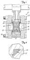
- seal 30according to the present invention is shown.
- the sealis continuous and has a shape selected to match the sealing cavity into which it is to be installed, in this case a circular shape.
- seal 30is shown in cross section placed in circular sealing groove or cavity 22.
- Cavity 22is defined by groove walls 24, 26, which are part of the pressure sensing cell 12, and by groove wall 28 which is a beveled circular edge of flange 16.
- the groove walls 24, 26, and 28are arranged in cross-section in a generally triangular configuration.
- a seal 30 according to the present inventionis placed between the groove walls 24, 26, and 28 between the mating cell 12 and the flange 16.
- the sealcomprises a ring 32 formed of resin material having first and second outer ring walls 34, 36 conformable to the first and second groove walls 24, 28 and having a third ring wall 38 with a continuous slot 42 extending into the ring.
- the ring 32is preferably formed of a polymer such as Teflon polytetrafluoroethylene which has resilient characteristics allowing it to conform to the groove walls 24, 28 to seal when force is applied.
- the groove walls 24, 28preferably have a very smooth, highly polished surface to effect a seal with the ring 32 without use of excessive sealing force.
- the resin ring 32has a generally triangular shape to fit the cavity 22, but the corners of the ring 32 are truncated to avoid high forces that would otherwise be encountered when these corners are squeezed together as the bolts 18 are tightened.
- Continuous slot 42is shaped to receive a coil spring and has a protrusion 44 near its opening to wall 38 which serves as a retainer for a coil spring.
- Coil spring 50is continuous and is positioned in the slot 42 such that, upon mating of the parts, the third wall presses the coil spring 50 toward the slot 42, compressing the coil spring to sealingly force the first and second outer ring walls against the first and second groove walls respectively with a controlled force, the coil spring's compression controlling the sealing force to limit undesired distortion of the groove walls.
- the third wall 26can either press directly on the coil spring 50, or the third wall 26 can press on coil spring 50 indirectly through a portion of ring 32, or the third wall 26 can press on the coil spring by a combination of both direct and indirect pressing as shown in Figure 4.
- An insert of harder materialcan also be included in the cavity 22 at 54 to limit extrusion of the ring out of the cavity if desired.
- the coil spring 50is preferably a helically wound coil spring which is wound to be slanted to provide improved spring characteristics.
- the outer shape of the spring winding 50can be round or oval as shown in Fig. 4.
Landscapes
- Engineering & Computer Science (AREA)
- General Engineering & Computer Science (AREA)
- Mechanical Engineering (AREA)
- Gasket Seals (AREA)
- Diaphragms And Bellows (AREA)
Abstract
Description
- This invention relates to spring-loaded rings formed of deformable resin material for compressing between mating parts to provide a fluid seal around isolator diaphragms in pressure transmitters. Spring-loaded resin seals are known, for example, as taught in USA Patent 4,508,356 to Janian, hereby incorporated herein by reference.
- In pressure transmitters, a continuous sealing groove generally encircles an isolator diaphragm on the transmitter to receive a seal which, in turn, seals to a flange which delivers process fluid to the transmitter as shown in cross-section in FIG.1. To meet the requirements of chemical, pressure and temperature cycling compatibility, various seal shapes and materials are used.
- In some applications, a resin polymer material, polytetrafluoroethylene, is selected for the seal and formed in a generally triangular shape to fit the groove. After compression in the groove, as shown in FIG. 2, a portion of the seal material can extrude out of the groove. In some applications, a backup ring made of less resilient material is placed in the groove along with the seal to prevent extrusion of the ring outside of the groove. In applications where the temperature changes cyclically, the seal material extrudes out at high temperatures and then when the transmitter is returned to a lower temperature, the sealing force originally placed on the seal is reduced. Over time, the seal can develop leaks because of this reduced sealing force, and the flange must be retightened, or in some cases, the seal must be replaced. The high sealing force used can deflect the walls of the groove and deflect the adjacent isolator diaphragm leading to errors in the pressure transmitter output which requires re-calibration of the output. The high sealing force used can also cause instability of the transmitter output as the force varies with temperature.
- Seals formed of a metal shell surrounding a central spring also are used, but the metal shell has limited ability to deform to seal to the groove surfaces, and exerts very large forces on the seal surfaces which deflect the isolator diaphragm enough to undesirably shift the calibration of the pressure transmitter.
- Pressure transmitter seals surrounding isolator diaphragms present a special sealing problem because there is a desire for a relatively high initial sealing force to ensure complete sealing after temperature cycling, but a conflicting need to reduce the sealing force to a controlled level to avoid undue deflection of the isolator diaphragm from distortion of the surrounding seal groove. A more robust seal for pressure transmitters is desired which maintains an adequate sealing force over temperature cycling while also presenting a deformable surface to form a seal to the groove walls, without using excess force which would deflect the isolator diaphragm by an unacceptable amount.
- GB-A-735801 discloses a seal arrangement between first and second parts comprising a seal for placement between first, second and third continuous groove walls of a continuous groove formed between said first and second parts and bounding a space to be sealed, said seal providing sealing between a surface of a second groove wall formed by a wall of the second part, and a surface of the first groove wall formed on the first part, the third groove wall being formed on the first part and being substantially perpendicular to the first groove wall, the seal comprising:
- a continuous ring formed of a resin material having first and second outer ring walls conformable to the surfaces of the first and second groove walls, and having a third ring wall positioned generally parallel to the third groove wall, said ring having a cavity, and
- a continuous coil spring formed to fit within the cavity, the coil spring being compressed to sealingly force the first and second ring walls against the first and second groove walls respectively with a controlled force, the compression of the coil spring controlling the sealing force to limit undesired distortion of the groove walls.
- A seal arrangement according to the present invention is characterised in that
the said second groove wall is oblique of both the first and third groove walls, such that the groove has a substantially triangular cross section, in that said third ring wall has a continuous slot extending into the ring defined by a pair of parallel surfaces which in turn are generally parallel to the surface of the second groove wall, in that said slot defines said cavity, and in that the coil spring has a portion of its surface engaged by the surface of the third groove wall, the mating parts being movable toward each other for effecting sealing, the arrangement being such that the surface of the second groove wall creates a force on the ring which tends to cause the coil spring to expand in direction outwardly of the slot and against the third groove wall. - The coil spring's compression controls the sealing force to limit undesired distortion of the groove walls. The controlled sealing force provides a reliable seal under temperature cycling conditions. In a preferred embodiment, the resin ring comprises the polymer polytetrafluoroethylene, which resists attack from many process chemicals used with pressure transmitters.
- Figure 1 is a cross-sectional view of a PRIOR ART arrangement of a continuous sealing groove surrounding isolator diaphragms in a pressure transmitter.
- Figure 2 is a cross-sectional view of a PRIOR ART polytetrafluoroethylene seal after compression in the sealing groove of FIG. 1.
- In Figure 3, a front view of an embodiment of a seal according to the present invention is shown.
- In Figure 4, a cross-section view of the seal of FIG. 3 disposed in a sealing groove is shown.
- In FIG. 1, a PRIOR
ART pressure transmitter 10 is shown in cross-section. Pressure sensingcell 12 inpressure transmitter 10 includesisolator diaphragms 14 which isolatepressure sensing cell 12 from process fluids, but are deflectable to transfer pressure insidecell 12 for sensing.Isolator diaphragms 14 are welded around their outer rims to the cell body. When the outer rims ofisolator diaphragms 14 are distorted, this deflects the isolator diaphragms and gives a false, undesired indication of a pressure change. Process fluids are coupled to the transmitter byflanges 16 which are attached totransmitter 10 bybolts 18. A continuous,circular sealing cavity 22 is formed between circular rims oncell 12 and beveled edges onflanges 16.Seals 24, which can be O-rings, metal seals, or solid Dupont Teflon ® polytetrafluoroethylene seals are placed incircular sealing cavity 22, and thenbolts 18 are tightened to place a sealing force on the seal selected. - In FIG. 2, a PRIOR ART Teflon
seal 24, which is originally triangular in shape, is shown in cross-section in sealingcavity 22 after compression by tighteningbolts 18. A portion of the seal has extruded out ofcavity 22. A second ring of harder resinous material know as a "backup ring" (not shown) is sometimes placed near the opening ofcavity 22 to contain the teflon and reduce problems with the material extruding out of the groove. As stated above, the seal has a limited life in temperature cycling applications and exerts excessive force on theadjacent isolator diaphragm 14 which results in pressure measurement errors. - In FIG. 3,
seal 30 according to the present invention is shown. The seal is continuous and has a shape selected to match the sealing cavity into which it is to be installed, in this case a circular shape. - In FIG. 4,
seal 30 is shown in cross section placed in circular sealing groove orcavity 22.Cavity 22 is defined bygroove walls pressure sensing cell 12, and bygroove wall 28 which is a beveled circular edge offlange 16. Thegroove walls seal 30 according to the present invention is placed between thegroove walls mating cell 12 and theflange 16. The seal comprises aring 32 formed of resin material having first and secondouter ring walls second groove walls third ring wall 38 with acontinuous slot 42 extending into the ring. Thering 32 is preferably formed of a polymer such as Teflon polytetrafluoroethylene which has resilient characteristics allowing it to conform to thegroove walls groove walls ring 32 without use of excessive sealing force. Theresin ring 32 has a generally triangular shape to fit thecavity 22, but the corners of thering 32 are truncated to avoid high forces that would otherwise be encountered when these corners are squeezed together as thebolts 18 are tightened. Continuous slot 42 is shaped to receive a coil spring and has aprotrusion 44 near its opening towall 38 which serves as a retainer for a coil spring.Coil spring 50 is continuous and is positioned in theslot 42 such that, upon mating of the parts, the third wall presses thecoil spring 50 toward theslot 42, compressing the coil spring to sealingly force the first and second outer ring walls against the first and second groove walls respectively with a controlled force, the coil spring's compression controlling the sealing force to limit undesired distortion of the groove walls. Thethird wall 26 can either press directly on thecoil spring 50, or thethird wall 26 can press oncoil spring 50 indirectly through a portion ofring 32, or thethird wall 26 can press on the coil spring by a combination of both direct and indirect pressing as shown in Figure 4.- An insert of harder material can also be included in the
cavity 22 at 54 to limit extrusion of the ring out of the cavity if desired. - The
coil spring 50 is preferably a helically wound coil spring which is wound to be slanted to provide improved spring characteristics. The outer shape of the spring winding 50 can be round or oval as shown in Fig. 4.
Claims (9)
- A seal arrangement between first and second parts (12, 16) comprising a seal (30) for placement between first, second and third continuous groove walls (24, 26, 28) of a continuous groove (22) formed between said first and second parts (12, 16) and bounding a space to be sealed, said seal (30) providing sealing between a surface of a second groove wall (28) formed by a wall of the second part (16), and a surface of the first groove wall (24) formed on the first part (12), the third groove wall (26) being formed on the first part (12) and being substantially perpendicular to the first groove wall (24), the seal (30) comprising:a continuous ring (32) formed of a resin material having first and second outer ring walls (34, 36) conformable to the surfaces of the first and second groove walls (24, 28), and having a third ring wall (38) positioned generally parallel to the third groove wall (26), said ring (32) having a cavity (42), anda continuous coil spring (50) formed to fit within the cavity (42), the coil spring (50) being compressed to sealingly force the first and second ring walls (34, 36) against the first and second groove walls (24, 28) respectively with a controlled force, the compression of the coil spring (50) controlling the sealing force to limit undesired distortion of the groove walls,characterised in that
the said second groove wall (28) is oblique of both the first and third groove walls (24, 26), such that the groove (22) has a substantially triangular cross section, in that said third ring wall (38) has a continuous slot (42) extending into the ring defined by a pair of parallel surfaces which in turn are generally parallel to the surface of the second groove wall (28), in that said slot (42) defines said cavity, and in that the coil spring (50) has a portion of its surface engaged by the surface of the third groove wall (26), the mating parts being movable toward each other for effecting sealing, the arrangement being such that the surface of the second groove wall (28) creates a force on the ring (32) which tends to cause the coil spring (50) to expand in direction outwardly of the slot (42) and against the third groove wall (26). - The seal arrangement of claim 1 wherein the ring (32) is formed of a material which comprises a polymer.
- The seal arrangement of claim 2 wherein the polymer comprises polytetrafluoroethylene.
- The seal arrangement of claim 3 wherein the material forming the ring (32) further comprises a filler material.
- The seal arrangement of any one of claims 1 to 4 wherein the slot (42) has a central axis on a locus of lines inclined relative to the axis of mating of the parts.
- The seal arrangement of any one of the preceding claims wherein the coil spring (50) is oval in cross-section, the length of the oval being substantially parallel to the pair of parallel surfaces of the slot.
- The seal arrangement of any one of claims 1 to 5 wherein the coil spring (50) is a helically wound coil spring.
- The seal arrangement of claim 7 wherein the coil spring (50) is oval in cross-section.
- The seal arrangement of any one of the preceding claims wherein a protrusion (44) is provided near the opening of the continuous slot (42), the protrusion (44) serving as a retainer for the coil spring (50).
Applications Claiming Priority (3)
| Application Number | Priority Date | Filing Date | Title |
|---|---|---|---|
| US07/763,822US5236202A (en) | 1991-09-23 | 1991-09-23 | Spring loaded resin seal |
| US763822 | 1991-09-23 | ||
| PCT/US1992/007855WO1993006390A1 (en) | 1991-09-23 | 1992-09-17 | Spring loaded resin seal |
Publications (3)
| Publication Number | Publication Date |
|---|---|
| EP0607230A4 EP0607230A4 (en) | 1994-06-02 |
| EP0607230A1 EP0607230A1 (en) | 1994-07-27 |
| EP0607230B1true EP0607230B1 (en) | 1997-03-12 |
Family
ID=25068912
Family Applications (1)
| Application Number | Title | Priority Date | Filing Date |
|---|---|---|---|
| EP92920959AExpired - LifetimeEP0607230B1 (en) | 1991-09-23 | 1992-09-17 | Spring loaded resin seal |
Country Status (8)
| Country | Link |
|---|---|
| US (1) | US5236202A (en) |
| EP (1) | EP0607230B1 (en) |
| JP (1) | JPH06511070A (en) |
| CN (1) | CN1071495A (en) |
| CA (1) | CA2115148A1 (en) |
| DE (1) | DE69218231T2 (en) |
| RU (1) | RU2091650C1 (en) |
| WO (1) | WO1993006390A1 (en) |
Families Citing this family (33)
| Publication number | Priority date | Publication date | Assignee | Title |
|---|---|---|---|---|
| US5314165A (en)* | 1993-07-14 | 1994-05-24 | Bray International, Inc. | Rotary valve |
| JP3437312B2 (en)* | 1995-02-16 | 2003-08-18 | 株式会社リケン | Seal ring and sealing device |
| US7134354B2 (en)* | 1999-09-28 | 2006-11-14 | Rosemount Inc. | Display for process transmitter |
| US6487912B1 (en) | 1999-09-28 | 2002-12-03 | Rosemount Inc. | Preinstallation of a pressure sensor module |
| US6571132B1 (en) | 1999-09-28 | 2003-05-27 | Rosemount Inc. | Component type adaptation in a transducer assembly |
| US6484107B1 (en) | 1999-09-28 | 2002-11-19 | Rosemount Inc. | Selectable on-off logic modes for a sensor module |
| JP3798693B2 (en) | 1999-09-28 | 2006-07-19 | ローズマウント インコーポレイテッド | Perimeter-sealed instrument loop adapter |
| US6510740B1 (en) | 1999-09-28 | 2003-01-28 | Rosemount Inc. | Thermal management in a pressure transmitter |
| US6765968B1 (en) | 1999-09-28 | 2004-07-20 | Rosemount Inc. | Process transmitter with local databus |
| US6401546B1 (en) | 2000-02-15 | 2002-06-11 | P I Components Corporation | Press-fit remote diaphragm assembly |
| US6546805B2 (en) | 2000-03-07 | 2003-04-15 | Rosemount Inc. | Process fluid transmitter with an environmentally sealed service block |
| US6662662B1 (en) | 2000-05-04 | 2003-12-16 | Rosemount, Inc. | Pressure transmitter with improved isolator system |
| US6504489B1 (en) | 2000-05-15 | 2003-01-07 | Rosemount Inc. | Process control transmitter having an externally accessible DC circuit common |
| US6480131B1 (en) | 2000-08-10 | 2002-11-12 | Rosemount Inc. | Multiple die industrial process control transmitter |
| US6516672B2 (en) | 2001-05-21 | 2003-02-11 | Rosemount Inc. | Sigma-delta analog to digital converter for capacitive pressure sensor and process transmitter |
| US6684711B2 (en) | 2001-08-23 | 2004-02-03 | Rosemount Inc. | Three-phase excitation circuit for compensated capacitor industrial process control transmitters |
| US7109883B2 (en)* | 2002-09-06 | 2006-09-19 | Rosemount Inc. | Low power physical layer for a bus in an industrial transmitter |
| US7773715B2 (en) | 2002-09-06 | 2010-08-10 | Rosemount Inc. | Two wire transmitter with isolated can output |
| US7036381B2 (en)* | 2004-06-25 | 2006-05-02 | Rosemount Inc. | High temperature pressure transmitter assembly |
| US7525419B2 (en)* | 2006-01-30 | 2009-04-28 | Rosemount Inc. | Transmitter with removable local operator interface |
| JP5166742B2 (en)* | 2006-02-14 | 2013-03-21 | トヨタ自動車株式会社 | Damping gasket and manufacturing method thereof, manifold gasket |
| US8511972B2 (en)* | 2009-12-16 | 2013-08-20 | Siemens Energy, Inc. | Seal member for use in a seal system between a transition duct exit section and a turbine inlet in a gas turbine engine |
| US8334788B2 (en) | 2010-03-04 | 2012-12-18 | Rosemount Inc. | Process variable transmitter with display |
| CN103335103A (en)* | 2013-07-12 | 2013-10-02 | 昆山新莱洁净应用材料股份有限公司 | Sealing mechanism without dead angle |
| CN106133412B (en)* | 2014-04-04 | 2018-07-31 | 川崎重工业株式会社 | Sealed construction of shell elements |
| BR112016023078B1 (en)* | 2014-05-05 | 2022-08-02 | Sulzer Management Ag | SEALING ARRANGEMENT FOR A HIGH PRESSURE PUMP AND HIGH PRESSURE PUMP WITH SUCH SEALING ARRANGEMENT |
| EP3198132B1 (en)* | 2014-09-23 | 2018-11-28 | Continental Automotive GmbH | Adjustment device for a fuel injection valve and fuel-injection system |
| JP2018520324A (en)* | 2015-07-28 | 2018-07-26 | サン−ゴバン パフォーマンス プラスティックス コーポレイション | seal |
| US10746037B2 (en) | 2016-11-30 | 2020-08-18 | Rolls-Royce Corporation | Turbine shroud assembly with tandem seals |
| US10480337B2 (en) | 2017-04-18 | 2019-11-19 | Rolls-Royce North American Technologies Inc. | Turbine shroud assembly with multi-piece seals |
| JP7095445B2 (en)* | 2018-07-18 | 2022-07-05 | 株式会社デンソー | Seal ring and valve device using it |
| DE102019205356A1 (en)* | 2019-04-12 | 2020-10-15 | Zf Friedrichshafen Ag | Process for creating a connection between two components |
| CN110500406B (en)* | 2019-06-27 | 2021-02-19 | 北京七星华创流量计有限公司 | Sealing structure and mass flow controller |
Family Cites Families (25)
| Publication number | Priority date | Publication date | Assignee | Title |
|---|---|---|---|---|
| GB735801A (en)* | 1953-05-22 | 1955-08-31 | Rolls Royce | Improvements relating to fluid seals |
| DE957704C (en)* | 1955-03-23 | 1957-02-07 | Ziefle Kg Eisenbau Albert | Seal for pipe connections |
| FR1231867A (en)* | 1959-04-17 | 1960-10-04 | Dispositifs Oleo Pneumatiques | Seals for corrosive fluids |
| US3129021A (en)* | 1959-12-03 | 1964-04-14 | Aeroquip Corp | Flexible joint |
| US3223426A (en)* | 1964-08-03 | 1965-12-14 | Aeroquip Corp | Sealing ring |
| US3258279A (en)* | 1964-11-30 | 1966-06-28 | Robert R Rcddy | Connector seal |
| US3508736A (en)* | 1967-05-24 | 1970-04-28 | Rockwell Mfg Co | Seat ring assemblies for valves |
| US3635499A (en)* | 1969-02-24 | 1972-01-18 | Robert R Reddy | Lip seal |
| US3653670A (en)* | 1970-05-11 | 1972-04-04 | Cascade Corp | Spring-loaded seal with symmetrical cross section |
| US3680874A (en)* | 1970-08-24 | 1972-08-01 | Federal Mogul Corp | Flexible pneumatic duct connectors assembled with internal seals |
| US3827558A (en)* | 1972-11-09 | 1974-08-06 | Donaldson Co Inc | Fluid filter with bypass and condition indicator |
| US3895833A (en)* | 1974-02-19 | 1975-07-22 | Certain Teed Prod Corp | Flange connector assembly for grooved pipe |
| DE2644419C3 (en)* | 1976-09-30 | 1979-05-17 | Borsig Gmbh, 1000 Berlin | Drive pin sealing of a ball valve |
| US4143883A (en)* | 1978-02-07 | 1979-03-13 | Controlex Corporation Of America | Push-pull control with spring-loaded seal |
| US4173129A (en)* | 1978-04-13 | 1979-11-06 | Caterpillar Tractor Co. | Universal joint structure with improved seal |
| US4239242A (en)* | 1978-12-18 | 1980-12-16 | Burns William G | Pipe union and seal |
| US4228917A (en)* | 1979-05-07 | 1980-10-21 | E. I. Du Pont De Nemours And Company | Gasket for yarn spinning pack |
| US4328972A (en)* | 1980-12-10 | 1982-05-11 | Parker-Hannifin Corporation | Seal ring and method of manufacture |
| US4508356A (en)* | 1984-06-06 | 1985-04-02 | Robert Janian | Modified C-shaped mechanical spring seal |
| US4655462A (en)* | 1985-01-07 | 1987-04-07 | Peter J. Balsells | Canted coiled spring and seal |
| DD240767A1 (en)* | 1985-09-09 | 1986-11-12 | Polygraph Leipzig | DEVICE FOR SEALING A ROTATING ANGLE ENGINE |
| US4850600A (en)* | 1987-11-05 | 1989-07-25 | Siemens Aktiengesellschaft | Sealing device for pipe connectors discharging into a vessel, in particular a steam generator |
| US5108078A (en)* | 1988-04-25 | 1992-04-28 | Peter J. Balsells | Canted-coil spring loaded while in a cavity |
| US4974821A (en)* | 1988-04-25 | 1990-12-04 | Peter J. Balsells | Canted-coil spring with major axis radial loading |
| US4907788A (en)* | 1988-04-25 | 1990-03-13 | Peter J. Balsells | Dual concentric canted-coil spring apparatus |
- 1991
- 1991-09-23USUS07/763,822patent/US5236202A/ennot_activeExpired - Lifetime
- 1992
- 1992-09-17EPEP92920959Apatent/EP0607230B1/ennot_activeExpired - Lifetime
- 1992-09-17CACA002115148Apatent/CA2115148A1/ennot_activeAbandoned
- 1992-09-17WOPCT/US1992/007855patent/WO1993006390A1/enactiveIP Right Grant
- 1992-09-17DEDE69218231Tpatent/DE69218231T2/ennot_activeExpired - Lifetime
- 1992-09-17JPJP5506212Apatent/JPH06511070A/enactivePending
- 1992-09-17RURU9294019484Apatent/RU2091650C1/enactive
- 1992-09-22CNCN92110984Apatent/CN1071495A/enactivePending
Also Published As
| Publication number | Publication date |
|---|---|
| DE69218231D1 (en) | 1997-04-17 |
| WO1993006390A1 (en) | 1993-04-01 |
| RU2091650C1 (en) | 1997-09-27 |
| EP0607230A4 (en) | 1994-06-02 |
| CN1071495A (en) | 1993-04-28 |
| DE69218231T2 (en) | 1997-08-07 |
| US5236202A (en) | 1993-08-17 |
| CA2115148A1 (en) | 1993-04-01 |
| EP0607230A1 (en) | 1994-07-27 |
| JPH06511070A (en) | 1994-12-08 |
Similar Documents
| Publication | Publication Date | Title |
|---|---|---|
| EP0607230B1 (en) | Spring loaded resin seal | |
| US6039319A (en) | Hygienic fitting with thermal expansion area for gasket | |
| RU2524587C2 (en) | Pressure relief device, having support element with recessed areas | |
| EP0646738B1 (en) | Fluid sealing means | |
| US3931834A (en) | Expansion tank diaphragm assembly | |
| US5947533A (en) | Gasket assembly with elastomer expansion area | |
| US4109535A (en) | Diaphragm seal for pressure sensing instrument | |
| US4371179A (en) | T-Shaped sealing ring with elongated lip | |
| CA1154044A (en) | Self-compensation gasket for grooved end pipe couplings | |
| EP1180631B1 (en) | Hose end fitting | |
| EP0961895B1 (en) | Hygienic flange-type tube joint thermal expansion area for gasket | |
| KR20010021281A (en) | Liquid container | |
| EP1982101B1 (en) | Sealed flange joint for high pressure and high purity gas channels | |
| US20020014123A1 (en) | Press-fit remote diaphragm assembly | |
| US5955675A (en) | Self energizing process seal for process control transmitter | |
| EP0009368A1 (en) | Pipe coupling and pipe joint connection | |
| EP0084538B1 (en) | Sealing assembly in fluid coupling | |
| US6481761B2 (en) | Frusto-conical seal fitting | |
| EP1197686B1 (en) | Superelastic seal for liquid natural gas processing plants | |
| GB2157374A (en) | Ring seal | |
| US3983902A (en) | Means for mounting a diaphragm in an accumulator-reservoir device | |
| US4285896A (en) | Isostatic molding process and seal | |
| JPS6263022A (en) | Device for expanding pipe section by hydraulic pressure | |
| WO2001014779A1 (en) | Improved hygienic fitting with thermal expansion area for gasket | |
| CA2282606C (en) | Hygienic flange-type tube joint thermal expansion area for gasket |
Legal Events
| Date | Code | Title | Description |
|---|---|---|---|
| A4 | Supplementary search report drawn up and despatched | ||
| AK | Designated contracting states | Kind code of ref document:A4 Designated state(s):DE GB | |
| PUAI | Public reference made under article 153(3) epc to a published international application that has entered the european phase | Free format text:ORIGINAL CODE: 0009012 | |
| 17P | Request for examination filed | Effective date:19940224 | |
| AK | Designated contracting states | Kind code of ref document:A1 Designated state(s):DE GB | |
| 17Q | First examination report despatched | Effective date:19951102 | |
| GRAG | Despatch of communication of intention to grant | Free format text:ORIGINAL CODE: EPIDOS AGRA | |
| GRAH | Despatch of communication of intention to grant a patent | Free format text:ORIGINAL CODE: EPIDOS IGRA | |
| GRAH | Despatch of communication of intention to grant a patent | Free format text:ORIGINAL CODE: EPIDOS IGRA | |
| GRAA | (expected) grant | Free format text:ORIGINAL CODE: 0009210 | |
| RAP1 | Party data changed (applicant data changed or rights of an application transferred) | Owner name:ROSEMOUNT INC. | |
| AK | Designated contracting states | Kind code of ref document:B1 Designated state(s):DE GB | |
| REF | Corresponds to: | Ref document number:69218231 Country of ref document:DE Date of ref document:19970417 | |
| PLBE | No opposition filed within time limit | Free format text:ORIGINAL CODE: 0009261 | |
| STAA | Information on the status of an ep patent application or granted ep patent | Free format text:STATUS: NO OPPOSITION FILED WITHIN TIME LIMIT | |
| 26N | No opposition filed | ||
| PGFP | Annual fee paid to national office [announced via postgrant information from national office to epo] | Ref country code:GB Payment date:19990902 Year of fee payment:8 | |
| PG25 | Lapsed in a contracting state [announced via postgrant information from national office to epo] | Ref country code:GB Free format text:LAPSE BECAUSE OF NON-PAYMENT OF DUE FEES Effective date:20000917 | |
| GBPC | Gb: european patent ceased through non-payment of renewal fee | Effective date:20000917 | |
| PGFP | Annual fee paid to national office [announced via postgrant information from national office to epo] | Ref country code:DE Payment date:20100929 Year of fee payment:19 | |
| REG | Reference to a national code | Ref country code:DE Ref legal event code:R071 Ref document number:69218231 Country of ref document:DE | |
| REG | Reference to a national code | Ref country code:DE Ref legal event code:R071 Ref document number:69218231 Country of ref document:DE | |
| PG25 | Lapsed in a contracting state [announced via postgrant information from national office to epo] | Ref country code:DE Free format text:LAPSE BECAUSE OF EXPIRATION OF PROTECTION Effective date:20120918 |