EP0605281B1 - Method of vectorial noise reduction in speech and device for performing said method - Google Patents
Method of vectorial noise reduction in speech and device for performing said methodDownload PDFInfo
- Publication number
- EP0605281B1 EP0605281B1EP93403076AEP93403076AEP0605281B1EP 0605281 B1EP0605281 B1EP 0605281B1EP 93403076 AEP93403076 AEP 93403076AEP 93403076 AEP93403076 AEP 93403076AEP 0605281 B1EP0605281 B1EP 0605281B1
- Authority
- EP
- European Patent Office
- Prior art keywords
- microphones
- signals
- source
- noise
- filter
- Prior art date
- Legal status (The legal status is an assumption and is not a legal conclusion. Google has not performed a legal analysis and makes no representation as to the accuracy of the status listed.)
- Expired - Lifetime
Links
- 238000000034methodMethods0.000titleclaimsdescription29
- 230000009467reductionEffects0.000titleclaimsdescription5
- 230000003044adaptive effectEffects0.000claimsdescription12
- 238000007792additionMethods0.000claimsdescription8
- 239000011159matrix materialSubstances0.000claimsdescription5
- 230000009466transformationEffects0.000claimsdescription3
- 230000035945sensitivityEffects0.000claimsdescription2
- 230000005236sound signalEffects0.000claims5
- 230000001360synchronised effectEffects0.000claims1
- 239000013598vectorSubstances0.000description16
- 238000012545processingMethods0.000description11
- 230000008569processEffects0.000description7
- 238000010586diagramMethods0.000description6
- 238000001914filtrationMethods0.000description6
- 238000005070samplingMethods0.000description4
- 230000001755vocal effectEffects0.000description3
- 238000003491arrayMethods0.000description2
- 238000004364calculation methodMethods0.000description2
- 230000014509gene expressionEffects0.000description2
- 230000010363phase shiftEffects0.000description2
- 238000004458analytical methodMethods0.000description1
- 238000013459approachMethods0.000description1
- 230000005540biological transmissionEffects0.000description1
- 230000015572biosynthetic processEffects0.000description1
- 230000000903blocking effectEffects0.000description1
- 238000004891communicationMethods0.000description1
- 238000000354decomposition reactionMethods0.000description1
- 230000007547defectEffects0.000description1
- 230000003111delayed effectEffects0.000description1
- 238000013461designMethods0.000description1
- 239000006185dispersionSubstances0.000description1
- 238000005516engineering processMethods0.000description1
- 238000005259measurementMethods0.000description1
- 230000037361pathwayEffects0.000description1
- 238000011160researchMethods0.000description1
- 238000001228spectrumMethods0.000description1
Images


Classifications
- G—PHYSICS
- G01—MEASURING; TESTING
- G01S—RADIO DIRECTION-FINDING; RADIO NAVIGATION; DETERMINING DISTANCE OR VELOCITY BY USE OF RADIO WAVES; LOCATING OR PRESENCE-DETECTING BY USE OF THE REFLECTION OR RERADIATION OF RADIO WAVES; ANALOGOUS ARRANGEMENTS USING OTHER WAVES
- G01S3/00—Direction-finders for determining the direction from which infrasonic, sonic, ultrasonic, or electromagnetic waves, or particle emission, not having a directional significance, are being received
- G01S3/80—Direction-finders for determining the direction from which infrasonic, sonic, ultrasonic, or electromagnetic waves, or particle emission, not having a directional significance, are being received using ultrasonic, sonic or infrasonic waves
- G01S3/86—Direction-finders for determining the direction from which infrasonic, sonic, ultrasonic, or electromagnetic waves, or particle emission, not having a directional significance, are being received using ultrasonic, sonic or infrasonic waves with means for eliminating undesired waves, e.g. disturbing noises
- G—PHYSICS
- G01—MEASURING; TESTING
- G01S—RADIO DIRECTION-FINDING; RADIO NAVIGATION; DETERMINING DISTANCE OR VELOCITY BY USE OF RADIO WAVES; LOCATING OR PRESENCE-DETECTING BY USE OF THE REFLECTION OR RERADIATION OF RADIO WAVES; ANALOGOUS ARRANGEMENTS USING OTHER WAVES
- G01S3/00—Direction-finders for determining the direction from which infrasonic, sonic, ultrasonic, or electromagnetic waves, or particle emission, not having a directional significance, are being received
- G01S3/80—Direction-finders for determining the direction from which infrasonic, sonic, ultrasonic, or electromagnetic waves, or particle emission, not having a directional significance, are being received using ultrasonic, sonic or infrasonic waves
- G01S3/802—Systems for determining direction or deviation from predetermined direction
- G01S3/805—Systems for determining direction or deviation from predetermined direction using adjustment of real or effective orientation of directivity characteristics of a transducer or transducer system to give a desired condition of signal derived from that transducer or transducer system, e.g. to give a maximum or minimum signal
- H—ELECTRICITY
- H04—ELECTRIC COMMUNICATION TECHNIQUE
- H04R—LOUDSPEAKERS, MICROPHONES, GRAMOPHONE PICK-UPS OR LIKE ACOUSTIC ELECTROMECHANICAL TRANSDUCERS; DEAF-AID SETS; PUBLIC ADDRESS SYSTEMS
- H04R3/00—Circuits for transducers, loudspeakers or microphones
Definitions
- the present inventionrelates to a denoising process speech vector and an implementation device.
- FIG. 1shows a conventional device for implementation of such a method.
- This deviceessentially comprises a noisy signal source (speech signal) 1 connected to the input + of a subtractor 2.
- a single noise source 3is connected via an adaptive filter 4 at the subtractor subtraction input 2.
- the subtractor output 2which constitutes the outlet of the denoiser, is also connected to the inlet of control of the filter 4 to send it a residual error signal ⁇ .
- Source 3constitutes a noise model, within the meaning of a certain criterion, for example the minimization of a quadratic error, this noise being adaptively subtracted from the noisy signal.
- the operating principle of this deviceis based on a postulate according to which there is stationarity of the useful signal s, of the noise n o affecting this signal, of the noise model n 1 and of the output signal y of the filter 4, and that, more, there is a decorrelation between s and n o , and between s and n 1 , and that there is a strong correlation between n o and n 1 .
- the output of filter 4is adjusted so that Emin is minimized. This minimization of the total output power leads to a reduction in the power of the noise, and consequently to maximization of the signal / noise ratio.
- the adaptive filter 4is of the LMS (Least Mean Square, that is to say minimization of the quadratic error) type, or else of the RLS (Recursive Least Square) type.
- This solutionconsists essentially to be treated by DFT (discrete Fourier transform) the noisy signal, and to produce, from its power value, the signal y to subtract from it through the discrete Fourier transform inverse of this power.
- DFTdiscrete Fourier transform
- This treatmentconsists in breaking down the noisy useful signal in independent sub-bands, for example by Fourier analysis, then to treat each sub-band independently to increase the size of the observation vector space. This kind of cutting is unusable for speech processing, since we knows that the speech signal is not frequently stationary, and does not occupy, statistically, the same frequency bands (which occurs for example with neighboring structures).
- Speech outputaffects all microphone output signals 5, the differences between these signals being mainly due to the difference in propagation time between the speaker and the different microphones.
- spatial processingconsists in form an antenna by forming conventional channels (generally by linear combinations of the signals of microphones), to detect by phase shift (or by pure delay) the lobe directivity of the antenna thus formed. The limitations mentioned above for the other known methods remain valid.
- the present inventionrelates to a denoising process speech vector to obtain a noise source of reference with the best possible correlation with noise affecting noisy speech, regardless of the vocal content of the noisy speech, without particular constraints for frequency or duration of the speech signal.
- the present inventionalso relates to a device for implementation of this process, a device which is simple and inexpensive.
- the method according to the inventionconsists in carrying out a vector sound recording using at least four evenly spaced microphones arranged in front of the signal source to be processed, to be sampled synchronously the signals from all microphones, to form linear combinations by additions and subtractions of signals of said microphones, so as to obtain, in the direction of the source a main sensitivity lobe, the sum of all the output signals microphones representing the noisy signal, the other combinations, each comprising as many subtractions as additions of signals, and being used as noise sources alone and processed by a filter adaptive vector to produce an estimate of the noise subtracted from the noisy signal.
- the inventionis described below with reference to denoising of the vocal emission of a speaker located in a noisy environment, but it is good understood that it is not limited to such an application, and can be used used for denoising useful signals from any sound source that we can assume to be punctual and located in a noisy environment, and possibly mobile.
- the speakerat a usual distance from it (distance of about 1 to 4 m for example) two sets each comprising for example eight aligned and evenly spaced microphones.
- the step of the distance between neighboring microphonesis for example of the order of a few centimeters about ten centimeters.
- the maximum frequency processedis: fmax: C / 2d, or approximately 1.7 kHz, C being the speed of sound in air.
- These two setsare for example arranged in a cross.
- the number of microphones and their layoutmay be different.
- These microphonescan example be four or another multiple of four for each set, and they can for example be arranged in the form of "V", in a circle.
- these two setsare coplanar.
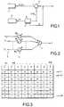
- the eight microphones of each of these two setsare referenced M1 to M8. Their output signals are combined with one another in eight different combinations.
- One of these combinations(1st row of the table in FIG. 3) provides a resulting signal S1, and it is the one corresponding to the addition of all these signals.
- the other seven combinationseach have four additions and four subtractions and respectively provide the resulting signals S2 to S8.
- the signal S1corresponds to the main directional lobe of a conventional channel
- the other signals S2 to S8can be considered as those produced by "noise" pathways only ", since having a zero in the direction of the main lobe.
- represented in FIG. 4the diagram giving the arbitrary value U of the directivity lobe on the different outputs S1 to S8 defined above, for each of the two sets of microphones, depending on the angle formed between the perpendicular to the plane of the two sets of microphones and the different measurement directions.
- the abscissasare graduated in values of ⁇ / d, ⁇ being the speed of sound and d the pitch of microphones ..
- a prior pointing of all the microphones towards the source soundcan use any known process suitable, for example a broadband super-resolving method, such as AR, Capon, Music ... to determine the site and the source deposit sound.
- a broadband super-resolving methodsuch as AR, Capon, Music ...
- the output signals from all microphonesare sampled synchronously. So we have signals taken all at the same time. The stationarity of noise affecting all these signals is thus ensured.
- the weights of the different broadband filterscan be calculated by one of the super-resolving methods shown in the table below.
- Wis the weight vector of the filters
- D ( ⁇ ) and D + ( ⁇ )are respectively the conventional vector and its conjugate transpose
- ⁇ xis the interspectral matrix
- ⁇ x + and ⁇ x -1are respectively the transpose conjugate of ⁇ x
- the inverse (or the pseudo-inverse) of ⁇ xthe parameters ⁇ k and V denote the smallest eigenvalue of ⁇ x and the associated eigenvector.
- Eis the vector made up of the noise power for its first component (the other components being zero).
- the processing of the different channelsis broadband, the covariance matrix is then an interspectral matrix (correlation matrix of the observation vectors).
- the two-dimensional network of microphones arranged in a crossallows the site and the source of the sound source to be evaluated by detecting the maximum of the function ⁇ k /
- This slavingis done by electronic pointing (in the manner of tracking radar antennas) of the network of microphones by varying the phase shift applied to their respective signals.
- Vector processing by error minimization quadratic, and, equivalently, the search for optimal filtering,are generally carried out by iterative research techniques gradient.
- ⁇designates the incrementation step of the algorithm, which is positive and constant. On the value of this step depend the speed, the residual variance, and the finesse of convergence of the algorithm.
- the LMS algorithmallows to minimize the mean square error of an adaptive device compared to a reference signal ("noise only”) which we know the value at each sampling instant.
- This algorithmis advantageous because it has good stability, but it is of course possible to use other algorithms, for example that of the least recursive square (RLS) whose speed of convergence is higher. However, a compromise must be sought between the speed of convergence and the residual variance of the estimation error.
- a set of eight equally spaced microphonesis shown at 8 M'1 to M'8.
- the other set 9, drawn in broken lines,is arranged crosswise with respect to the first and coplanar with the latter.
- the microphones of this second setare identical to those of the microphones in set 8 up to the location, and have not been shown for clarity of design.
- Each of the microphones in set 8is followed by a preamplifier (the whole of which is referenced 10), of a device sampling (the whole of which is referenced 11) and a filter non-recursive transverse (the whole of which is referenced 12).
- the exits microphones M'2, M'4, M'6 and M'8are connected to an adder 13.
- the outputs of the filters of the assembly 12 relating to microphones M'3 to M'6are connected to another adder 14.
- the output of the adder 13is connected via a filter compensator 15 (for example of the FIR type) at a first entry of a adder 16, and the output of adder 14 is connected via a filter 17, identical to filter 15, to a second input of adder 16.
- a filter compensator 15for example of the FIR type
- the output of the adder 16is connected to a device 18 of location of the speaker.
- This site control device 18 and deposit of the two sets of microphones 8 and 9is of the super-resolving type, operating according to one of the methods mentioned above.
- the samplers 11 of the microphones M'1 to M'8are by elsewhere connected to a combiner device 19 with binary transformation, type described above with reference to Figure 3.
- the "main lobe" output (combination comprising only additions) of the combiner 19is connected to the input (+) of a subtractor 20.
- the other seven outputs of "noise only”are connected via an adaptive filter 21 to the input (-) of the subtractor 20.
- the two sets of microphones 8 and 9provide a double spatial sampling of the speaker's voice broadcast.
- the compensating filters 15 and 17correct the dispersions between the extreme frequencies of the received sound spectrum.
- the signals from the two filters 15, 17are added at 16.
- We obtain so at the exit of 16a constant directivity lobe (corresponding to main lobes of sets 8 and 9). This is true when normal to the plane formed by the sets 8 and 9 (we assimilate the microphones to coplanar points) and passing through the point of intersection C of sets 8 and 9 is directed to the speaker (also assumed punctual).
- the locator servo device 18directs the plan in site and / or deposit, in a manner known per se microphones to find at the output of 16 the maximum of one functional.
- FIG. 5Schematically is shown in Figure 5 an embodiment of the broadband adaptive filter 21 of Figure 6.
- This filtercomprises, for each of the (L-1) channels of microphones x o x L an elementary filter, respectively referenced 22 o to 22 L.
- Each of these elementary filterscomprises, in a manner known per se, k cascade processing blocks.
- Each processing blockessentially comprises a delay cell Z -1 (for example in the form of a buffer register), and a convolution cell W i, j (i going from o to L for channels 22 o to 22 L and j going from o to k-1 in each channel).
- the first processing block(W o, o to W L, o ) does not include a delay cell.
- the outputs of channels 22 o to 22 Lare connected to a parallel adder 23.
- the weights of the various processing blocks(coefficients affecting the delayed discrete values processed by each processing block) are slaved to the output signal of the adder 20.
Landscapes
- Physics & Mathematics (AREA)
- Engineering & Computer Science (AREA)
- General Physics & Mathematics (AREA)
- Radar, Positioning & Navigation (AREA)
- Remote Sensing (AREA)
- Acoustics & Sound (AREA)
- Signal Processing (AREA)
- Circuit For Audible Band Transducer (AREA)
- Filters That Use Time-Delay Elements (AREA)
- Cable Transmission Systems, Equalization Of Radio And Reduction Of Echo (AREA)
Description
Translated fromFrenchLa présente invention se rapporte à un procédé de débruitagevectoriel de la parole et à un dispositif de mise en oeuvre.The present invention relates to a denoising processspeech vector and an implementation device.
Des procédés connus de débruitage de la parole font appelau filtrage linéaire. On a représenté en figure 1 un dispositif classique demise en oeuvre d'un tel procédé. Ce dispositif comporte essentiellementune source de signal bruitée (signal de parole) 1 reliée à l'entrée + d'unsoustracteur 2. Une source 3 de bruit seul est reliée via un filtre adaptatif4 à l'entrée de soustraction du soustracteur 2. La sortie du soustracteur2 qui constitue la sortie du débruiteur, est par ailleurs reliée à l'entrée decommande du filtre 4 pour lui envoyer un signal ε d'erreur résiduelle.Known methods for denoising speech uselinear filtering. FIG. 1 shows a conventional device forimplementation of such a method. This device essentially comprisesa noisy signal source (speech signal) 1 connected to the input + of asubtractor 2. A single noise source 3 is connected via an adaptive filter4 at the subtractor subtraction input 2. The subtractor output2 which constitutes the outlet of the denoiser, is also connected to the inlet ofcontrol of the filter 4 to send it a residual error signal ε.
La source 3 constitue un modèle de bruit, au sens d'un certaincritère, par exemple la minimisation d'une erreur quadratique, ce bruitétant soustrait adaptativement du signal bruité. Le principe defonctionnement de ce dispositif repose sur un postulat selon lequel il y astationnarité du signal utile s, du bruit no affectant ce signal, du modèlede bruit n1 et du signal de sortie y du filtre 4, et que, de plus, il existeune décorrélation entre s et no, et entre s et n1, et qu'il existe une fortecorrélation entre no et n1.Source 3 constitutes a noise model, within the meaning of a certain criterion, for example the minimization of a quadratic error, this noise being adaptively subtracted from the noisy signal. The operating principle of this device is based on a postulate according to which there is stationarity of the useful signal s, of the noise no affecting this signal, of the noise model n1 and of the output signal y of the filter 4, and that, more, there is a decorrelation between s and no , and between s and n1 , and that there is a strong correlation between no and n1 .
Le signal de sortie e vaut :
soit :
is :
Le signal de sortie n'étant pas affecté par le filtrage adaptatif,
on a :
we have :
La sortie du filtre 4 est ajustée de façon que Emin soitminimisée. Cette minimisation de la puissance totale de sortie conduit àune réduction de la puissance du bruit, et par voie de conséquence àune maximisation du rapport signal/bruit.The output of filter 4 is adjusted so that Emin isminimized. This minimization of the total output power leads toa reduction in the power of the noise, and consequently tomaximization of the signal / noise ratio.
Au mieux, on obtient :
En d'autres termes, lorsque le signal de la source 3 n'est pasdécorrélé du signal de la source 1, on a :
Le principal défaut de cette solution connue est l'impérieusenécessité de disposer physiquement de cette source de bruit 3. Cettesource peut comporter une part plus ou moins importante de signaux neprésentant pas les caractéristiques du bruit seul. Les performances duprocédé de débruitage en sont alors largement affectées, comme ledémontrent les calculs théoriques classiques, qui ne sont pas repris ici.The main shortcoming of this known solution is the imperiousneed to physically have this noise source 3. Thissource can contain a more or less significant part of signalsnot having the characteristics of noise alone. The performance ofdenoising process are then largely affected, as thedemonstrate the classical theoretical calculations, which are not repeated here.
Une première possibilité pour remédier à ce défaut serait demettre en oeuvre la "diversité fréquentielle". Cette solution consisteessentiellement à traiter par DFT (transformée de Fourier discrète) lesignal bruité, et à produire, à partir de sa valeur de puissance, le signaly à en soustraire en passant par la transformée de Fourier discrèteinverse de cette puissance. Ce traitement consiste à décomposer lesignal utile bruité en sous-bandes indépendantes, par exemple paranalyse de Fourier, puis à traiter chaque sous-bande indépendammentpour augmenter la taille de l'espace vectoriel d'observation. Ce type dedécoupage est inexploitable pour le traitement de la parole, puisque l'on sait que le signal de parole n'est pas fréquentiellement stationnaire, etn'occupe pas, statistiquement, les mêmes bandes fréquentielles (ce quise produit par exemple avec les structures voisées).A first possibility to remedy this defect would be toimplement "frequency diversity". This solution consistsessentially to be treated by DFT (discrete Fourier transform) thenoisy signal, and to produce, from its power value, the signaly to subtract from it through the discrete Fourier transforminverse of this power. This treatment consists in breaking down thenoisy useful signal in independent sub-bands, for example byFourier analysis, then to treat each sub-band independentlyto increase the size of the observation vector space. This kind ofcutting is unusable for speech processing, since weknows that the speech signal is not frequently stationary, anddoes not occupy, statistically, the same frequency bands (whichoccurs for example with neighboring structures).
Une autre solution serait l'exploitation de la "diversitétemporelle". Cette solution n'est pas non plus exploitable, car lastationnarité de l'émission vocale n'est pas physiquement réaliste. Toutau plus, on pourrait observer une stationnarité sur quelques dizaines detrames de 25,6 ms (correspondant à 256 points d'un signal échantillonnéà 10 kHz) pour des noyaux vocaliques stables, mais cette stationnaritéserait réduite à une durée égale à celle de 1 à 3 trames pour desplosives (sons tels que "t").Another solution would be the exploitation of "diversityThis solution is not usable either, because thestationarity of voice transmission is not physically realistic. Allat most, we could observe stationarity over a few dozen25.6 ms frames (corresponding to 256 points of a sampled signalat 10 kHz) for stable vocal nuclei, but this stationaritywould be reduced to a duration equal to that of 1 to 3 frames forplosives (sounds such as "t").
Une dernière solution serait la "diversité spatiale", quiconsiste à répartir dans l'espace plusieurs points de prise de signal(prise d'information vectorielle). Le filtrage serait alors réalisé commeschématiquement représenté en figure 2.A final solution would be "spatial diversity", whichconsists of distributing several signal pickup points in space(taking vector information). Filtering would then be carried out asschematically shown in Figure 2.
On dispose, face à un locuteur, un ensemble 5 de (L+1)microphones qui peuvent par exemple être équi-espacés, dont lessignaux de sortie sont notés xo, x1 ... xL. Chacun de ces microphonesest suivi d'un filtre adaptatif bande étroite, dont l'ensemble est référencé6, ces filtres étant respectivement référencés Wo, W1 ... WL. Leurssorties sont reliées à un sommateur 7 dont la sortie constitue celle dudispositif.We have, facing a speaker, a set 5 of (L + 1) microphones which can, for example, be equally spaced, whose output signals are denoted xo , x1 ... xL. Each of these microphones is followed by an adaptive narrow band filter, the assembly of which is referenced 6, these filters being respectively referenced Wo , W1 ... WL. Their outputs are connected to an adder 7, the output of which constitutes that of the device.
On note Xk l'un quelconque des vecteurs d'entrée, WkT levecteur transposé, du poids à appliquer au filtre, et gk le scalaire desortie.We denote by Xk any of the input vectors, WkT the transposed vector, of the weight to be applied to the filter, and gk the output scalar.
On a :
A un instant donné (déterminé par exemple paréchantillonnage et blocage), on dispose de L signaux d'entrée.L'émission de parole affecte tous les signaux de sortie des microphones5, les différences entre ces signaux étant principalement dues à ladifférence de temps de propagation entre le locuteur et les différents microphones. De façon connue en soi, le traitement spatial consiste àformer une antenne par formation de voies conventionnelles(généralement par combinaisons linéaires des signaux desmicrophones), pour dépointer par déphasage (ou par retard pur) le lobede directivité de l'antenne ainsi formée. Les limitations citées ci-dessuspour les autres procédés connus restent valables.At a given time (determined for example bysampling and blocking), there are L input signals.Speech output affects all microphone output signals5, the differences between these signals being mainly due to thedifference in propagation time between the speaker and the differentmicrophones. In a manner known per se, spatial processing consists inform an antenna by forming conventional channels(generally by linear combinations of the signals ofmicrophones), to detect by phase shift (or by pure delay) the lobedirectivity of the antenna thus formed. The limitations mentioned abovefor the other known methods remain valid.
On connaít d'après les documents IEEE TRANSACTIONS ONVEHICULAR TECHNOLOGY, vol. 40, n° 1, février 1991, NEW YORKUS, pages 194-202, INGVAR CLAESSON ET AL. 〈 A Multi-DSPImplementation of a Broad-Band Adaptative Beamformer for Use in aHands-Free Mobile Radio Telephone 〉, SPEECH COMMUNICATION,vol. 9, n° 5/6, décembre 1990, AMSTERDAM NL, pages 433-442, DIRKVAN COMPERNOLLE ET AL. 〈 Speech Recognition in NoisyEnvironments with the Aid of Microphone Arrays 〉, et IEEETRANSACTIONS ON ANTENNAS AND PROPAGATION, vol. AP-30,n° 1, janvier 1982, NEW YORK US, pages 27-34, LLOYD J. GRIFFITHSET AL. 〈 An Alternative Approach to Linearly Constrained AdaptativeBeamforming 〉 des procédés de débruitage à l'aide de dispositionsclassiques, rectilignes, de microphones, présentant également l'une aumoins des limitations précitées.We know from the documents IEEE TRANSACTIONS ONVEHICULAR TECHNOLOGY, vol. 40, n ° 1, February 1991, NEW YORKUS, pages 194-202, INGVAR CLAESSON ET AL. 〈A Multi-DSPImplementation of a Broad-Band Adaptative Beamformer for Use in aHands-Free Mobile Radio Telephone〉, SPEECH COMMUNICATION,flight. 9, n ° 5/6, December 1990, AMSTERDAM NL, pages 433-442, DIRKVAN COMPERNOLLE ET AL. 〈Speech Recognition in NoisyEnvironments with the Aid of Microphone Arrays〉, and IEEETRANSACTIONS ON ANTENNAS AND PROPAGATION, vol. AP-30,n ° 1, January 1982, NEW YORK US, pages 27-34, LLOYD J. GRIFFITHSET AL. 〈An Alternative Approach to Linearly Constrained AdaptativeBeamforming〉 denoising processes using arrangementsclassical, rectilinear, microphone, also having one atless of the above limitations.
La présente invention a pour objet un procédé de débruitagevectoriel de la parole permettant d'obtenir une source de bruit deréférence présentant la meilleure corrélation possible avec le bruitaffectant la parole bruitée, et ce, quel que soit le contenu vocalique de laparole bruitée, sans contraintes particulières pour la fréquence ou ladurée du signal de parole.The present invention relates to a denoising processspeech vector to obtain a noise source ofreference with the best possible correlation with noiseaffecting noisy speech, regardless of the vocal content of thenoisy speech, without particular constraints for frequency orduration of the speech signal.
La présente invention a également pour objet un dispositif demise en oeuvre de ce procédé, dispositif qui soit simple et peu onéreux.The present invention also relates to a device forimplementation of this process, a device which is simple and inexpensive.
Le procédé conforme à l'invention consiste à effectuer uneprise de son vectorielle à l'aide d'au moins quatre microphones équiespacésdisposés devant la source de signaux à traiter, à échantillonnerde façon synchrone les signaux de tous les microphones, à former descombinaisons linéaires par additions et soustractions des signaux desdits microphones, de façon à obtenir, dans la direction de la sourceun lobe principal de sensibilité, la somme de tous les signaux de sortiedes microphones représentant le signal bruité, les autres combinaisons,comportant chacune autant de soustractions que d'additions de signaux,et étant utilisées en tant que sources de bruit seul et traitées par un filtrevectoriel adaptatif pour produire une estimation du bruit que l'onsoustrait au signal bruité.The method according to the invention consists in carrying out avector sound recording using at least four evenly spaced microphonesarranged in front of the signal source to be processed, to be sampledsynchronously the signals from all microphones, to formlinear combinations by additions and subtractions of signalsof said microphones, so as to obtain, in the direction of the sourcea main sensitivity lobe, the sum of all the output signalsmicrophones representing the noisy signal, the other combinations,each comprising as many subtractions as additions of signals,and being used as noise sources alone and processed by a filteradaptive vector to produce an estimate of the noisesubtracted from the noisy signal.
La présente invention sera mieux comprise à la lecture de ladescription détaillée d'un mode de réalisation, pris à titre d'exemple nonlimitatif, et illustrée par le dessin annexé, sur lequel :
- les figures 1 et 2, déjà décrites ci-dessus, sont des blocs-diagrammesde dispositifs de débruitage et de filtrage connus ;
- la figure 3 est un tableau d'un exemple, conforme à l'invention, decombinaisons linéaires de signaux de sortie d'un ensemble de huitmicrophones ;
- la figure 4 représente les quatre premiers diagrammes de directivitéd'un ensemble de huit microphones, disposés, conformément àl'invention, face à un locuteur ;
- la figure 5 est un bloc-diagramme d'un dispositif de filtrage à largebande utilisé dans le dispositif de l'invention ; et
- la figure 6 est un bloc-diagramme d'un dispositif débruiteur conforme àl'invention.
- Figures 1 and 2, already described above, are block diagrams of known denoising and filtering devices;
- FIG. 3 is a table of an example, according to the invention, of linear combinations of output signals from a set of eight microphones;
- FIG. 4 represents the first four directivity diagrams of a set of eight microphones, arranged, in accordance with the invention, facing a speaker;
- FIG. 5 is a block diagram of a broadband filtering device used in the device of the invention; and
- Figure 6 is a block diagram of a denoising device according to the invention.
L'invention est décrite ci-dessous en référence au débruitagede l'émission vocale d'un locuteur situé en milieu bruité, mais il est bienentendu qu'elle n'est pas limitée à une telle application, et peut être miseen oeuvre pour le débruitage des signaux utiles de toute source sonoreque l'on peut supposer ponctuelle et située en milieu bruité, etéventuellement mobile.The invention is described below with reference to denoisingof the vocal emission of a speaker located in a noisy environment, but it is goodunderstood that it is not limited to such an application, and can be usedused for denoising useful signals from any sound sourcethat we can assume to be punctual and located in a noisy environment, andpossibly mobile.
Dans l'exemple décrit ci-dessous, on dispose face aulocuteur, à une distance habituelle de celui-ci (distance d'environ 1 à4 m par exemple) deux ensembles comportant chacun par exemple huitmicrophones alignés et équi-espacés. Le pas de la distance entremicrophones voisins est par exemple de l'ordre de quelques centimètresà une dizaine de centimètres environ. A titre d'exemple, pour un pasd = 10 cm, la fréquence maximale traitée est: fmax: C/2d, soit environ1,7 kHz, C étant la vitesse du son dans l'air. Ces deux ensembles sontpar exemple disposés en croix. Toutefois, le nombre de microphones etleur disposition peuvent être différentes. Ces microphones peuvent parexemple être au nombre de quatre ou d'un autre multiple de quatre pourchaque ensemble, et ils peuvent être par exemple disposés en forme de"V", en cercle. De préférence, ces deux ensembles sont coplanaires.In the example described below, we have in front of thespeaker, at a usual distance from it (distance of about 1 to4 m for example) two sets each comprising for example eightaligned and evenly spaced microphones. The step of the distance betweenneighboring microphones is for example of the order of a few centimetersabout ten centimeters. For example, for one stepd = 10 cm, the maximum frequency processed is: fmax: C / 2d, or approximately1.7 kHz, C being the speed of sound in air. These two sets arefor example arranged in a cross. However, the number of microphones andtheir layout may be different. These microphones canexample be four or another multiple of four foreach set, and they can for example be arranged in the form of"V", in a circle. Preferably, these two sets are coplanar.
Les huit microphones de chacun de ces deux ensembles sontréférencés M1 à M8. Leurs signaux de sortie sont combinés entre euxselon huit combinaisons différentes. L'une de ces combinaisons (1èreligne du tableau de la figure 3) fournit un signal résultant S1, et elle estcelle correspondant à l'addition de tous ces signaux. Les sept autrescombinaisons comportent chacune quatre additions et quatresoustractions et fournissent respectivement les signaux résultants S2 à S8. Ainsi, par exemple, la combinaison de la deuxième ligne du tableaude la figure 3 correspond à l'addition des signaux de M1 à M4, lessignaux de M5 à M8 étant tous soustraits, donc
Il est à noter que ces huit combinaisons sont orthogonales(c'est-à-dire faisant partie d'une base de fonctions orthonormées tellequ'une base de décomposition de Haar). Le signal S1 correspond aulobe principal de directivité d'une voie classique, les autres signaux S2 àS8 peuvent être considérés comme ceux produits par des voies "bruitseul", puisque présentant un zéro dans la direction du lobe principal. Ona représenté en figure 4 le diagramme donnant la valeur arbitraire U dulobe de directivité sur les différentes sorties S1 à S8 définies ci-dessus,pour chacun des deux ensembles de microphones, en fonction del'angle formé entre la perpendiculaire au plan des deux ensembles demicrophones et les différentes directions de mesure. Les abscisses sontgraduées en valeurs de λ/d, λ étant la vitesse du son et d le pas desmicrophones..It should be noted that these eight combinations are orthogonal(i.e. forming part of a base of orthonormal functions suchthan a Haar decomposition base). The signal S1 corresponds to themain directional lobe of a conventional channel, the other signals S2 toS8 can be considered as those produced by "noise" pathwaysonly ", since having a zero in the direction of the main lobe.represented in FIG. 4 the diagram giving the arbitrary value U of thedirectivity lobe on the different outputs S1 to S8 defined above,for each of the two sets of microphones, depending onthe angle formed between the perpendicular to the plane of the two sets ofmicrophones and the different measurement directions. The abscissas aregraduated in values of λ / d, λ being the speed of sound and d the pitch ofmicrophones ..
Pour simplifier les explications, on suppose que lesmicrophones utilisés sont omnidirectionnels. Si l'on prend en compte desdiagrammes directifs, les explications exposées ici restent valables, àcondition, bien entendu, que tous les microphones soient identiques, ouque l'on compense leurs disparités (par pondération complexe enamplitude et phase).To simplify the explanations, it is assumed that themicrophones used are omnidirectional. If we take into accountdirective diagrams, the explanations presented here remain valid, exceptprovided, of course, that all microphones are identical, orthat we compensate for their disparities (by complex weighting inamplitude and phase).
Pour la mise en oeuvre du procédé de l'invention, on effectueun pointage préalable de l'ensemble des microphones vers la sourcesonore (le locuteur). Ce pointage peut faire appel à tout procédé connuapproprié, par exemple un procédé super-résolvant large bande, tel queAR, Capon, Music... pour déterminer le site et le gisement de la sourcesonore.For the implementation of the method of the invention,a prior pointing of all the microphones towards the sourcesound (the speaker). This score can use any known processsuitable, for example a broadband super-resolving method, such asAR, Capon, Music ... to determine the site and the source depositsound.
Il est important de noter que le procédé de l'invention nenécessite, pour la formation des voies "bruit seul", aucun calcul. Lescombinaisons décrites ci-dessus en référence au tableau de la figure 3 ne sont en fait que de simples mises en série (combinaisons "+") etl'utilisation d'inverseurs (pour les combinaisons "-").It is important to note that the method of the invention does notrequires no calculation for the formation of "noise only" channels. Thecombinations described above with reference to the table in Figure 3are in fact only simple serialization ("+" combinations) andthe use of reversers (for combinations "-").
Les signaux de sortie de tous les microphones sontéchantillonnés de manière synchrone. On dispose donc de signauxprélevés tous au même instant. La stationnarité du bruit affectant tousces signaux est ainsi assurée.The output signals from all microphones aresampled synchronously. So we have signalstaken all at the same time. The stationarity of noise affecting allthese signals is thus ensured.
Bien que, d'un point de vue spatial, il subsiste une ambiguïtégauche/droite par rapport au locuteur (les lobes des microphones sontsymétriques par rapport au milieu du réseau, comme c'est le cas pourdes lobes images de réseaux d'antennes), cette ambiguïté n'affecte pasle fonctionnement du débruiteur puisque les signaux élaborés sont d'unepart le signal somme de tous les signaux de microphones, et d'autre partceux de voies de "bruit". La détermination de la position du locuteur estfaite indépendamment de cette ambiguïté.Although, from a spatial point of view, there remains an ambiguityleft / right with respect to the speaker (the microbe lobes aresymmetrical with respect to the middle of the network, as is the case forimage lobes of antenna arrays), this ambiguity does not affectthe operation of the denoiser since the signals produced are of apart the signal sum of all the microphone signals, and secondlythose of "noise" tracks. Determining the speaker's position ismade regardless of this ambiguity.
Les poids des différents filtres large bande peuvent êtrecalculés par l'un des procédés super-résolvants figurant dans le tableauci-dessous.
Dans ce tableau W est le vecteur poids des filtres, D () etD+ () sont respectivement le vecteur conventionnel et son transposéconjugué, Γx est la matrice interspectrale, Γx+ etΓx-1sontrespectivement la transposée conjuguée de Γx, et l'inverse (ou lapseudo-inverse) de Γx, les paramètres λk et V désignent la plus petitevaleur propre de Γx et le vecteur propre associé. E est le vecteurconstitué de la puissance du bruit pour sa première composante (lesautres composantes étant nulles).In this table W is the weight vector of the filters, D () and D+ () are respectively the conventional vector and its conjugate transpose, Γx is the interspectral matrix, Γx+ and Γx-1 are respectively the transpose conjugate of Γx , and the inverse (or the pseudo-inverse) of Γx , the parameters λk and V denote the smallest eigenvalue of Γx and the associated eigenvector. E is the vector made up of the noise power for its first component (the other components being zero).
Le terme générique "super-résolvants" indique simplementque les procédés en question peuvent résoudre (discriminer) deuxsources séparées par une distance inférieure à λ/L (L étant la longueurtotale de l'antenne physique composée de la série de huit microphonesalignés et λ la longueur d'onde.The generic term "super-resolvers" simply indicatesthat the processes in question can solve (discriminate) twosources separated by a distance less than λ / L (L being the lengthtotal of the physical antenna composed of the series of eight microphonesaligned and λ the wavelength.
Le traitement des différentes voies est à large bande, lamatrice des covariances est alors une matrice interspectrale (matrice decorrélation des vecteurs d'observation). Le réseau bi-dimensionnel demicrophones disposés en croix permet d'évaluer le site et le gisement dela source sonore par détection du maximum de la fonction λk/|D+()V|2(figure 4), ce qui permet d'asservir le réseau à la position du locuteur.Cet asservissement se fait par pointage électronique (à la manière desantennes de radars de poursuite) du réseau de microphones en faisantvarier le déphasage appliqué à leurs signaux respectifs.The processing of the different channels is broadband, the covariance matrix is then an interspectral matrix (correlation matrix of the observation vectors). The two-dimensional network of microphones arranged in a cross allows the site and the source of the sound source to be evaluated by detecting the maximum of the function λk / |D+ ()V |2 (Figure 4), which allows the network to be controlled by the speaker's position. This slaving is done by electronic pointing (in the manner of tracking radar antennas) of the network of microphones by varying the phase shift applied to their respective signals.
Lorsque ce pointage est réalisé, on applique unetransformation binaire (figure 3) aux signaux issus des microphones, cequi fournit d'une part une voie signal bruité, et d'autre part sept voies"bruit seul" (dans le cas de 8 microphones). Un traitement vectoriel (dutype LMS ou RLS par exemple) permet de filtrer cette valeur estimée dubruit. La soustraction de cette valeur estimée dudit signal bruité permetde réaliser un débruitage adaptatif.When this score is achieved, abinary transformation (Figure 3) to signals from microphones, thiswhich provides on the one hand a noisy signal channel, and on the other hand seven channels"noise only" (in the case of 8 microphones). Vector processing (fromLMS or RLS type for example) allows this estimated value to be filterednoise. Subtracting this estimated value from said noisy signal allowsperform adaptive denoising.
Le traitement vectoriel par minimisation de l'erreurquadratique, et, de façon équivalente, la recherche du filtrage optimal,sont généralement réalisés par des techniques itératives de recherchede gradient.Vector processing by error minimizationquadratic, and, equivalently, the search for optimal filtering,are generally carried out by iterative research techniquesgradient.
Lorsque les signaux des microphones sont échantillonnés à lapériode Te avec
Dans ces équations µ désigne le pas d'incrémentation del'algorithme, qui est positif et constant. De la valeur de ce pas dépendentla vitesse, la variance résiduellle, et la finesse de convergence del'algorithme. Un algorithme avantageux pour la mise en oeuvre dutraitement vectoriel est l'algorithme du gradient stochastique, encoreappelé LMS. Cet algorithme utilise une estimation stochastique dugradient, de sorte que le vecteur de filtrage est ajusté conformément auxexpressions suivantes :
On a affaire ici à des expressions réelles puisque les signauxde parole sont considérés en bande de base, sans nécessité d'unedémodulation complexe.We are dealing here with real expressions since the signalsspeech are considered in baseband, without the need for acomplex demodulation.
L'algorithme LMS permet de minimiser l'erreur quadratiquemoyenne d'un dispositif adaptatif par rapport à un signal de référence("bruit seul") dont on connaít la valeur à chaque instantd'échantillonnage. Cet algorithme permet d'obtenir en moyenne lasolution optimale
On a schématiquement représenté en figure 6 un exemple deréalisation d'un dispositif de mise en oeuvre du procédé de l'invention.An example ofrealization of a device for implementing the method of the invention.
On a représenté en 8 un ensemble de huit microphones équi-espacésM'1 à M'8. L'autre ensemble 9, dessiné en traits interrompus,est disposé en croix par rapport au premier et coplanaire à celui-ci. Lesbranchements des microphones de ce second ensemble sont identiquesà ceux des microphones de l'ensemble 8 jusqu'au dispositif delocalisation, et n'ont pas été représentés pour la clarté du dessin.A set of eight equally spaced microphones is shown at 8M'1 to M'8. The other set 9, drawn in broken lines,is arranged crosswise with respect to the first and coplanar with the latter. Themicrophones of this second set are identicalto those of the microphones in set 8 up to thelocation, and have not been shown for clarity of design.
Chacun des microphones de l'ensemble 8 est suivi d'unpréamplificateur (dont l'ensemble est référencé 10), d'un dispositifd'échantillonnage (dont l'ensemble est référencé 11) et d'un filtretransversal non récursif (dont l'ensemble est référencé 12). Les sortiesdes microphones M'2, M'4, M'6 et M'8 sont reliées à un sommateur 13.Les sorties des filtres de l'ensemble 12 relatifs aux microphones M'3 àM'6 sont reliées à un autre sommateur 14.Each of the microphones in set 8 is followed by apreamplifier (the whole of which is referenced 10), of a devicesampling (the whole of which is referenced 11) and a filternon-recursive transverse (the whole of which is referenced 12). The exitsmicrophones M'2, M'4, M'6 and M'8 are connected to an adder 13.The outputs of the filters of the assembly 12 relating to microphones M'3 toM'6 are connected to another adder 14.
La sortie du sommateur 13 est reliée via un filtrecompensateur 15 (par exemple du type FIR) à une première entrée d'unsommateur 16, et la sortie du sommateur 14 est reliée via un filtre 17,identique au filtre 15, à une deuxième entrée du sommateur 16.The output of the adder 13 is connected via a filtercompensator 15 (for example of the FIR type) at a first entry of aadder 16, and the output of adder 14 is connected via a filter 17,identical to filter 15, to a second input of adder 16.
La sortie du sommateur 16 est reliée à un dispositif 18 delocalisation du locuteur. Ce dispositif 18 d'asservissement en site etgisement des deux ensembles de microphones 8 et 9 est du type super-résolvant,fonctionnant selon l'un des procédés mentionnés ci-dessus.The output of the adder 16 is connected to a device 18 oflocation of the speaker. This site control device 18 anddeposit of the two sets of microphones 8 and 9 is of the super-resolving type,operating according to one of the methods mentioned above.
Les échantillonneurs 11 des microphones M'1 à M'8 sont parailleurs reliés à un dispositif combineur 19 à transformation binaire, dutype décrit ci-dessus en référence à la figure 3. La sortie "lobe principal"(combinaison ne comportant que des additions) du combineur 19 estreliée à l'entrée (+) d'un soustracteur 20. Les sept autres sorties de"bruit seul" sont reliées via un filtre adaptatif 21 à l'entrée (-) dusoustracteur 20. Le filtre 21 est par exemple un filtre transversal, dontles coefficients sont recalculés à chaque trame de parole (1 trame = 25,6 ms par exemple) de façon à minimiser le bruit à la sortie dusoustracteur 20.The samplers 11 of the microphones M'1 to M'8 are byelsewhere connected to a combiner device 19 with binary transformation,type described above with reference to Figure 3. The "main lobe" output(combination comprising only additions) of the combiner 19 isconnected to the input (+) of a subtractor 20. The other seven outputs of"noise only" are connected via an adaptive filter 21 to the input (-) of thesubtractor 20. The filter 21 is for example a transverse filter, of whichthe coefficients are recalculated for each speech frame (1 frame =25.6 ms for example) so as to minimize the noise at the output of thesubtractor 20.
Les deux ensembles de microphones 8 et 9 réalisent undouble échantillonnage spatial de l'émission vocale du locuteur. Onforme aux sorties des sommateurs 13 et 14 deux antennes physiquesprésentant le même lobe principal, mais à deux fréquences séparéesd'une octave. Les filtres compensateurs 15 et 17 corrigent lesdispersions entre les fréquences extrêmes du spectre sonore reçu. Lessignaux issus des deux filtres 15, 17 sont additionnés en 16. On obtientdonc à la sortie de 16 un lobe de directivité constant (correspondant auxlobes principaux des ensembles 8 et 9). Ceci est vrai lorsque la normaleau plan formé par les ensembles 8 et 9 (on assimile les microphones àdes points coplanaires) et passant par le point d'intersection C desensembles 8 et 9 est dirigée vers le locuteur (lui aussi supposéponctuel). Lorsque ceci n'est pas le cas, l'un au moins des deux lobesprincipaux est décalé par rapport au centre (C) du diagramme dedirectivité correspondant, et le signal de sortie de 16 en est affecté(perte de puissance). Le dispositif d'asservissement du localisateur 18oriente alors en site et/ou en gisement, de façon connue en soi, le plande microphones pour retrouver à la sortie de 16 le maximum d'unefonctionnelle.The two sets of microphones 8 and 9 provide adouble spatial sampling of the speaker's voice broadcast. Weforms two physical antennas at the outputs of summers 13 and 14having the same main lobe, but at two separate frequenciesan octave. The compensating filters 15 and 17 correct thedispersions between the extreme frequencies of the received sound spectrum. Thesignals from the two filters 15, 17 are added at 16. We obtainso at the exit of 16 a constant directivity lobe (corresponding tomain lobes of sets 8 and 9). This is true when normalto the plane formed by the sets 8 and 9 (we assimilate the microphones tocoplanar points) and passing through the point of intersection C ofsets 8 and 9 is directed to the speaker (also assumedpunctual). When this is not the case, at least one of the two lobesmain is offset from the center (C) of thecorresponding directivity, and the output signal of 16 is affected(power loss). The locator servo device 18then directs the plan in site and / or deposit, in a manner known per semicrophones to find at the output of 16 the maximum of onefunctional.
On a représenté de façon simplifiée en figure 5 un exemplede réalisation du filtre adaptatif large bande 21 de la figure 6. Ce filtrecomporte, pour chacune des (L-1) voies de microphones xo à xL un filtreélémentaire, respectivement référencé 22o à 22L. Chacun de ces filtresélémentaires comporte, de façon connue en soi, k blocs de traitement encascade. Chaque bloc de traitement comporte essentiellement unecellule de retard Z-1 (par exemple sous forme d'un registre tampon), etune cellule de convolution Wi,j (i allant de o à L pour les voies 22o à 22Let j allant de o à k-1 dans chaque voie). Le premier bloc de traitement(Wo,o à WL,o) ne comporte pas de cellule de retard. Les sorties desvoies 22o à 22L sont reliées à un additionneur parallèle 23. Les poidsdes différents blocs de traitement (coefficients affectant les valeurs discrètes retardées traitées par chaque bloc de traitement) sont asservisau signal de sortie de l'additionneur 20.Schematically is shown in Figure 5 an embodiment of the broadband adaptive filter 21 of Figure 6. This filter comprises, for each of the (L-1) channels of microphones xo xL an elementary filter, respectively referenced 22o to 22L. Each of these elementary filters comprises, in a manner known per se, k cascade processing blocks. Each processing block essentially comprises a delay cell Z-1 (for example in the form of a buffer register), and a convolution cell Wi, j (i going from o to L for channels 22o to 22L and j going from o to k-1 in each channel). The first processing block (Wo, o to WL, o ) does not include a delay cell. The outputs of channels 22o to 22L are connected to a parallel adder 23. The weights of the various processing blocks (coefficients affecting the delayed discrete values processed by each processing block) are slaved to the output signal of the adder 20.
Claims (8)
- Method of vectorial noise reduction of asubstantially point source of sound signals, accordingto which a sound capture is performed with the aid ofat least four equispaced microphones (M1 ... M4)arranged in a plane in front of the source of signalsto be processed, characterized in that the signals fromall the microphones (11) are sampled synchronously, inthat linear combinations are formed by additions andsubtractions of the signals from the said microphonesso as to obtain, in the direction of the source, a mainsensitivity lobe, the sum of all the output signalsfrom the microphones representing the noisy signal, theother combinations each comprising as many subtractionsas additions of signals and being used as noise-onlysources and processed by an adaptive vectorial filter(21) so as to produce an estimate of the noise which issubtracted from the noisy signal.
- Method according to Claim 1, characterized inthat the microphones are arranged in two coplanar sets(8, 9) which intersect, the normal to the plane thusformed and passing through the point of intersection ofthe two sets being directed towards the source of soundsignals to be processed.
- Method according to Claim 2, characterized inthat for each set of microphones, the microphones formtwo physical antennas having the same main directivitylobe at two frequencies separated by an octave, and inthat the signals from these two antennas are added together (16) so as to slave (18) the orientation, inelevation and bearing, of the plane of microphones withrespect to the source of sound signals.
- Method according to either of Claims 2 and 3,characterized in that the elevational and bearingorientation of the plane of microphones with respect tothe source of sound signals is determined by asuper-resolving method.
- Method according to Claim 4, characterized inthat the super-resolving method is chosen from amongthe CAPON, LAGUNAS, AR or MUSIC methods.
- Method according to one of the precedingclaims, characterized in that the vectorial noisereduction implements an algorithm of the LMS or RLStype.
- Device for the vectorial noise reduction of asubstantially point source of sound signals,characterized in that it comprises at least one set (8,9) of at least four equispaced microphones (M'1 ...M'8) each followed by a preamplifier (10), by a sampler(11), the samplers all being synchronous, and linked toa binary transformation matrix (19) comprisingserializing connections and inverters, a first of itsoutputs (S1) corresponding to the placing in series ofall the inputs, its other outputs (S2 ... S8) eachcorresponding to a different combination ofserializations and inversions of inputs, the firstoutput (S1) of this combiner device being linked to theinput (+) of a subtractor (20), and the others beinglinked via an adaptive filter (21) to the input (-) ofthe subtractor.
- Device according to Claim 7, characterized inthat it comprises two orthogonal and coplanar sets (8,9) of microphones, the outputs of the samplers (11)each being linked via a filter (12), for each of thetwo sets, for a first portion of these outputs, to afirst summator (13), and for the other portion to asecond summator (14), the two summators each beinglinked via a compensating filter (15, 17) to another summator (16) whose output is linked to a device (18)for the positional slaving of the plane of microphones.
Applications Claiming Priority (2)
| Application Number | Priority Date | Filing Date | Title |
|---|---|---|---|
| FR9215904AFR2700055B1 (en) | 1992-12-30 | 1992-12-30 | Method for denoising vector speech and device for implementing it. |
| FR9215904 | 1992-12-30 |
Publications (2)
| Publication Number | Publication Date |
|---|---|
| EP0605281A1 EP0605281A1 (en) | 1994-07-06 |
| EP0605281B1true EP0605281B1 (en) | 2000-02-16 |
Family
ID=9437266
Family Applications (1)
| Application Number | Title | Priority Date | Filing Date |
|---|---|---|---|
| EP93403076AExpired - LifetimeEP0605281B1 (en) | 1992-12-30 | 1993-12-17 | Method of vectorial noise reduction in speech and device for performing said method |
Country Status (4)
| Country | Link |
|---|---|
| US (1) | US5500903A (en) |
| EP (1) | EP0605281B1 (en) |
| JP (1) | JPH06245291A (en) |
| FR (1) | FR2700055B1 (en) |
Families Citing this family (129)
| Publication number | Priority date | Publication date | Assignee | Title |
|---|---|---|---|---|
| US5862240A (en)* | 1995-02-10 | 1999-01-19 | Sony Corporation | Microphone device |
| JP2758846B2 (en)* | 1995-02-27 | 1998-05-28 | 埼玉日本電気株式会社 | Noise canceller device |
| FR2744277B1 (en)* | 1996-01-26 | 1998-03-06 | Sextant Avionique | VOICE RECOGNITION METHOD IN NOISE AMBIENCE, AND IMPLEMENTATION DEVICE |
| FR2744320B1 (en)* | 1996-01-26 | 1998-03-06 | Sextant Avionique | SOUND AND LISTENING SYSTEM FOR HEAD EQUIPMENT IN NOISE ATMOSPHERE |
| FR2744871B1 (en)* | 1996-02-13 | 1998-03-06 | Sextant Avionique | SOUND SPATIALIZATION SYSTEM, AND PERSONALIZATION METHOD FOR IMPLEMENTING SAME |
| US7146012B1 (en)* | 1997-11-22 | 2006-12-05 | Koninklijke Philips Electronics N.V. | Audio processing arrangement with multiple sources |
| US6173059B1 (en) | 1998-04-24 | 2001-01-09 | Gentner Communications Corporation | Teleconferencing system with visual feedback |
| US7209567B1 (en) | 1998-07-09 | 2007-04-24 | Purdue Research Foundation | Communication system with adaptive noise suppression |
| US20040066940A1 (en)* | 2002-10-03 | 2004-04-08 | Silentium Ltd. | Method and system for inhibiting noise produced by one or more sources of undesired sound from pickup by a speech recognition unit |
| JP2000115881A (en) | 1998-10-05 | 2000-04-21 | Matsushita Electric Ind Co Ltd | Sound collector |
| US8645137B2 (en) | 2000-03-16 | 2014-02-04 | Apple Inc. | Fast, language-independent method for user authentication by voice |
| US6668062B1 (en)* | 2000-05-09 | 2003-12-23 | Gn Resound As | FFT-based technique for adaptive directionality of dual microphones |
| GB2364121B (en)* | 2000-06-30 | 2004-11-24 | Mitel Corp | Method and apparatus for locating a talker |
| US7349849B2 (en)* | 2001-08-08 | 2008-03-25 | Apple, Inc. | Spacing for microphone elements |
| US20030033153A1 (en)* | 2001-08-08 | 2003-02-13 | Apple Computer, Inc. | Microphone elements for a computing system |
| US20030033144A1 (en)* | 2001-08-08 | 2003-02-13 | Apple Computer, Inc. | Integrated sound input system |
| US6874796B2 (en)* | 2002-12-04 | 2005-04-05 | George A. Mercurio | Sulky with buck-bar |
| US7783060B2 (en)* | 2005-05-10 | 2010-08-24 | The United States Of America As Represented By The Administrator Of The National Aeronautics And Space Administration | Deconvolution methods and systems for the mapping of acoustic sources from phased microphone arrays |
| US8170234B2 (en)* | 2005-05-10 | 2012-05-01 | The United States of America by the Administrator of the National Aeronautics and Space Adminstration | Deconvolution methods and systems for the mapping of acoustic sources from phased microphone arrays |
| DE102005039621A1 (en)* | 2005-08-19 | 2007-03-01 | Micronas Gmbh | Method and apparatus for the adaptive reduction of noise and background signals in a speech processing system |
| US8677377B2 (en) | 2005-09-08 | 2014-03-18 | Apple Inc. | Method and apparatus for building an intelligent automated assistant |
| US9318108B2 (en) | 2010-01-18 | 2016-04-19 | Apple Inc. | Intelligent automated assistant |
| US7995771B1 (en)* | 2006-09-25 | 2011-08-09 | Advanced Bionics, Llc | Beamforming microphone system |
| US8977255B2 (en) | 2007-04-03 | 2015-03-10 | Apple Inc. | Method and system for operating a multi-function portable electronic device using voice-activation |
| US9330720B2 (en) | 2008-01-03 | 2016-05-03 | Apple Inc. | Methods and apparatus for altering audio output signals |
| US8996376B2 (en) | 2008-04-05 | 2015-03-31 | Apple Inc. | Intelligent text-to-speech conversion |
| US10496753B2 (en) | 2010-01-18 | 2019-12-03 | Apple Inc. | Automatically adapting user interfaces for hands-free interaction |
| US20100030549A1 (en) | 2008-07-31 | 2010-02-04 | Lee Michael M | Mobile device having human language translation capability with positional feedback |
| WO2010067118A1 (en) | 2008-12-11 | 2010-06-17 | Novauris Technologies Limited | Speech recognition involving a mobile device |
| US9858925B2 (en) | 2009-06-05 | 2018-01-02 | Apple Inc. | Using context information to facilitate processing of commands in a virtual assistant |
| US10241644B2 (en) | 2011-06-03 | 2019-03-26 | Apple Inc. | Actionable reminder entries |
| US10241752B2 (en) | 2011-09-30 | 2019-03-26 | Apple Inc. | Interface for a virtual digital assistant |
| US20120309363A1 (en) | 2011-06-03 | 2012-12-06 | Apple Inc. | Triggering notifications associated with tasks items that represent tasks to perform |
| US9431006B2 (en) | 2009-07-02 | 2016-08-30 | Apple Inc. | Methods and apparatuses for automatic speech recognition |
| US10679605B2 (en) | 2010-01-18 | 2020-06-09 | Apple Inc. | Hands-free list-reading by intelligent automated assistant |
| US10705794B2 (en) | 2010-01-18 | 2020-07-07 | Apple Inc. | Automatically adapting user interfaces for hands-free interaction |
| US10276170B2 (en) | 2010-01-18 | 2019-04-30 | Apple Inc. | Intelligent automated assistant |
| US10553209B2 (en) | 2010-01-18 | 2020-02-04 | Apple Inc. | Systems and methods for hands-free notification summaries |
| DE112011100329T5 (en) | 2010-01-25 | 2012-10-31 | Andrew Peter Nelson Jerram | Apparatus, methods and systems for a digital conversation management platform |
| US8682667B2 (en) | 2010-02-25 | 2014-03-25 | Apple Inc. | User profiling for selecting user specific voice input processing information |
| US10762293B2 (en) | 2010-12-22 | 2020-09-01 | Apple Inc. | Using parts-of-speech tagging and named entity recognition for spelling correction |
| US9262612B2 (en) | 2011-03-21 | 2016-02-16 | Apple Inc. | Device access using voice authentication |
| KR20120128542A (en)* | 2011-05-11 | 2012-11-27 | 삼성전자주식회사 | Method and apparatus for processing multi-channel de-correlation for cancelling multi-channel acoustic echo |
| US10057736B2 (en) | 2011-06-03 | 2018-08-21 | Apple Inc. | Active transport based notifications |
| US8994660B2 (en) | 2011-08-29 | 2015-03-31 | Apple Inc. | Text correction processing |
| US10134385B2 (en) | 2012-03-02 | 2018-11-20 | Apple Inc. | Systems and methods for name pronunciation |
| US9483461B2 (en) | 2012-03-06 | 2016-11-01 | Apple Inc. | Handling speech synthesis of content for multiple languages |
| US9280610B2 (en) | 2012-05-14 | 2016-03-08 | Apple Inc. | Crowd sourcing information to fulfill user requests |
| US9721563B2 (en) | 2012-06-08 | 2017-08-01 | Apple Inc. | Name recognition system |
| US9495129B2 (en) | 2012-06-29 | 2016-11-15 | Apple Inc. | Device, method, and user interface for voice-activated navigation and browsing of a document |
| US9576574B2 (en) | 2012-09-10 | 2017-02-21 | Apple Inc. | Context-sensitive handling of interruptions by intelligent digital assistant |
| US9547647B2 (en) | 2012-09-19 | 2017-01-17 | Apple Inc. | Voice-based media searching |
| DE212014000045U1 (en) | 2013-02-07 | 2015-09-24 | Apple Inc. | Voice trigger for a digital assistant |
| US9368114B2 (en) | 2013-03-14 | 2016-06-14 | Apple Inc. | Context-sensitive handling of interruptions |
| AU2014233517B2 (en) | 2013-03-15 | 2017-05-25 | Apple Inc. | Training an at least partial voice command system |
| WO2014144579A1 (en) | 2013-03-15 | 2014-09-18 | Apple Inc. | System and method for updating an adaptive speech recognition model |
| WO2014197336A1 (en) | 2013-06-07 | 2014-12-11 | Apple Inc. | System and method for detecting errors in interactions with a voice-based digital assistant |
| US9582608B2 (en) | 2013-06-07 | 2017-02-28 | Apple Inc. | Unified ranking with entropy-weighted information for phrase-based semantic auto-completion |
| WO2014197334A2 (en) | 2013-06-07 | 2014-12-11 | Apple Inc. | System and method for user-specified pronunciation of words for speech synthesis and recognition |
| WO2014197335A1 (en) | 2013-06-08 | 2014-12-11 | Apple Inc. | Interpreting and acting upon commands that involve sharing information with remote devices |
| US10176167B2 (en) | 2013-06-09 | 2019-01-08 | Apple Inc. | System and method for inferring user intent from speech inputs |
| DE112014002747T5 (en) | 2013-06-09 | 2016-03-03 | Apple Inc. | Apparatus, method and graphical user interface for enabling conversation persistence over two or more instances of a digital assistant |
| AU2014278595B2 (en) | 2013-06-13 | 2017-04-06 | Apple Inc. | System and method for emergency calls initiated by voice command |
| DE112014003653B4 (en) | 2013-08-06 | 2024-04-18 | Apple Inc. | Automatically activate intelligent responses based on activities from remote devices |
| US9620105B2 (en) | 2014-05-15 | 2017-04-11 | Apple Inc. | Analyzing audio input for efficient speech and music recognition |
| US10592095B2 (en) | 2014-05-23 | 2020-03-17 | Apple Inc. | Instantaneous speaking of content on touch devices |
| US9502031B2 (en) | 2014-05-27 | 2016-11-22 | Apple Inc. | Method for supporting dynamic grammars in WFST-based ASR |
| US10170123B2 (en) | 2014-05-30 | 2019-01-01 | Apple Inc. | Intelligent assistant for home automation |
| US9633004B2 (en) | 2014-05-30 | 2017-04-25 | Apple Inc. | Better resolution when referencing to concepts |
| US9842101B2 (en) | 2014-05-30 | 2017-12-12 | Apple Inc. | Predictive conversion of language input |
| US9760559B2 (en) | 2014-05-30 | 2017-09-12 | Apple Inc. | Predictive text input |
| US9715875B2 (en) | 2014-05-30 | 2017-07-25 | Apple Inc. | Reducing the need for manual start/end-pointing and trigger phrases |
| US9734193B2 (en) | 2014-05-30 | 2017-08-15 | Apple Inc. | Determining domain salience ranking from ambiguous words in natural speech |
| US9430463B2 (en) | 2014-05-30 | 2016-08-30 | Apple Inc. | Exemplar-based natural language processing |
| CN110797019B (en) | 2014-05-30 | 2023-08-29 | 苹果公司 | Multi-command single speech input method |
| US10078631B2 (en) | 2014-05-30 | 2018-09-18 | Apple Inc. | Entropy-guided text prediction using combined word and character n-gram language models |
| US9785630B2 (en) | 2014-05-30 | 2017-10-10 | Apple Inc. | Text prediction using combined word N-gram and unigram language models |
| US10289433B2 (en) | 2014-05-30 | 2019-05-14 | Apple Inc. | Domain specific language for encoding assistant dialog |
| US10659851B2 (en) | 2014-06-30 | 2020-05-19 | Apple Inc. | Real-time digital assistant knowledge updates |
| US9338493B2 (en) | 2014-06-30 | 2016-05-10 | Apple Inc. | Intelligent automated assistant for TV user interactions |
| US10446141B2 (en) | 2014-08-28 | 2019-10-15 | Apple Inc. | Automatic speech recognition based on user feedback |
| US9818400B2 (en) | 2014-09-11 | 2017-11-14 | Apple Inc. | Method and apparatus for discovering trending terms in speech requests |
| US10789041B2 (en) | 2014-09-12 | 2020-09-29 | Apple Inc. | Dynamic thresholds for always listening speech trigger |
| US9668121B2 (en) | 2014-09-30 | 2017-05-30 | Apple Inc. | Social reminders |
| US10074360B2 (en) | 2014-09-30 | 2018-09-11 | Apple Inc. | Providing an indication of the suitability of speech recognition |
| US9646609B2 (en) | 2014-09-30 | 2017-05-09 | Apple Inc. | Caching apparatus for serving phonetic pronunciations |
| US10127911B2 (en) | 2014-09-30 | 2018-11-13 | Apple Inc. | Speaker identification and unsupervised speaker adaptation techniques |
| US9886432B2 (en) | 2014-09-30 | 2018-02-06 | Apple Inc. | Parsimonious handling of word inflection via categorical stem + suffix N-gram language models |
| US10552013B2 (en) | 2014-12-02 | 2020-02-04 | Apple Inc. | Data detection |
| US9711141B2 (en) | 2014-12-09 | 2017-07-18 | Apple Inc. | Disambiguating heteronyms in speech synthesis |
| US9865280B2 (en) | 2015-03-06 | 2018-01-09 | Apple Inc. | Structured dictation using intelligent automated assistants |
| US9721566B2 (en) | 2015-03-08 | 2017-08-01 | Apple Inc. | Competing devices responding to voice triggers |
| US9886953B2 (en) | 2015-03-08 | 2018-02-06 | Apple Inc. | Virtual assistant activation |
| US10567477B2 (en) | 2015-03-08 | 2020-02-18 | Apple Inc. | Virtual assistant continuity |
| US9899019B2 (en) | 2015-03-18 | 2018-02-20 | Apple Inc. | Systems and methods for structured stem and suffix language models |
| US9842105B2 (en) | 2015-04-16 | 2017-12-12 | Apple Inc. | Parsimonious continuous-space phrase representations for natural language processing |
| US10083688B2 (en) | 2015-05-27 | 2018-09-25 | Apple Inc. | Device voice control for selecting a displayed affordance |
| US10127220B2 (en) | 2015-06-04 | 2018-11-13 | Apple Inc. | Language identification from short strings |
| US10101822B2 (en) | 2015-06-05 | 2018-10-16 | Apple Inc. | Language input correction |
| US10255907B2 (en) | 2015-06-07 | 2019-04-09 | Apple Inc. | Automatic accent detection using acoustic models |
| US10186254B2 (en) | 2015-06-07 | 2019-01-22 | Apple Inc. | Context-based endpoint detection |
| US11025565B2 (en) | 2015-06-07 | 2021-06-01 | Apple Inc. | Personalized prediction of responses for instant messaging |
| US10747498B2 (en) | 2015-09-08 | 2020-08-18 | Apple Inc. | Zero latency digital assistant |
| US10671428B2 (en) | 2015-09-08 | 2020-06-02 | Apple Inc. | Distributed personal assistant |
| US9697820B2 (en) | 2015-09-24 | 2017-07-04 | Apple Inc. | Unit-selection text-to-speech synthesis using concatenation-sensitive neural networks |
| US10366158B2 (en) | 2015-09-29 | 2019-07-30 | Apple Inc. | Efficient word encoding for recurrent neural network language models |
| US11010550B2 (en) | 2015-09-29 | 2021-05-18 | Apple Inc. | Unified language modeling framework for word prediction, auto-completion and auto-correction |
| US11587559B2 (en) | 2015-09-30 | 2023-02-21 | Apple Inc. | Intelligent device identification |
| US10691473B2 (en) | 2015-11-06 | 2020-06-23 | Apple Inc. | Intelligent automated assistant in a messaging environment |
| US10049668B2 (en) | 2015-12-02 | 2018-08-14 | Apple Inc. | Applying neural network language models to weighted finite state transducers for automatic speech recognition |
| US10223066B2 (en) | 2015-12-23 | 2019-03-05 | Apple Inc. | Proactive assistance based on dialog communication between devices |
| US10446143B2 (en) | 2016-03-14 | 2019-10-15 | Apple Inc. | Identification of voice inputs providing credentials |
| US9934775B2 (en) | 2016-05-26 | 2018-04-03 | Apple Inc. | Unit-selection text-to-speech synthesis based on predicted concatenation parameters |
| US9972304B2 (en) | 2016-06-03 | 2018-05-15 | Apple Inc. | Privacy preserving distributed evaluation framework for embedded personalized systems |
| US10249300B2 (en) | 2016-06-06 | 2019-04-02 | Apple Inc. | Intelligent list reading |
| US10049663B2 (en) | 2016-06-08 | 2018-08-14 | Apple, Inc. | Intelligent automated assistant for media exploration |
| DK179309B1 (en) | 2016-06-09 | 2018-04-23 | Apple Inc | Intelligent automated assistant in a home environment |
| US10067938B2 (en) | 2016-06-10 | 2018-09-04 | Apple Inc. | Multilingual word prediction |
| US10586535B2 (en) | 2016-06-10 | 2020-03-10 | Apple Inc. | Intelligent digital assistant in a multi-tasking environment |
| US10192552B2 (en) | 2016-06-10 | 2019-01-29 | Apple Inc. | Digital assistant providing whispered speech |
| US10509862B2 (en) | 2016-06-10 | 2019-12-17 | Apple Inc. | Dynamic phrase expansion of language input |
| US10490187B2 (en) | 2016-06-10 | 2019-11-26 | Apple Inc. | Digital assistant providing automated status report |
| DK179049B1 (en) | 2016-06-11 | 2017-09-18 | Apple Inc | Data driven natural language event detection and classification |
| DK201670540A1 (en) | 2016-06-11 | 2018-01-08 | Apple Inc | Application integration with a digital assistant |
| DK179415B1 (en) | 2016-06-11 | 2018-06-14 | Apple Inc | Intelligent device arbitration and control |
| DK179343B1 (en) | 2016-06-11 | 2018-05-14 | Apple Inc | Intelligent task discovery |
| US10593346B2 (en) | 2016-12-22 | 2020-03-17 | Apple Inc. | Rank-reduced token representation for automatic speech recognition |
| DK179745B1 (en) | 2017-05-12 | 2019-05-01 | Apple Inc. | SYNCHRONIZATION AND TASK DELEGATION OF A DIGITAL ASSISTANT |
| DK201770431A1 (en) | 2017-05-15 | 2018-12-20 | Apple Inc. | Optimizing dialogue policy decisions for digital assistants using implicit feedback |
Family Cites Families (3)
| Publication number | Priority date | Publication date | Assignee | Title |
|---|---|---|---|---|
| US4363112A (en)* | 1980-04-18 | 1982-12-07 | Bernard Widrow | Apparatus and method for determining the position of a gas-saturated porous rock in the vicinity of a deep borehole in the earth |
| US4589137A (en)* | 1985-01-03 | 1986-05-13 | The United States Of America As Represented By The Secretary Of The Navy | Electronic noise-reducing system |
| FR2652164A1 (en)* | 1989-09-15 | 1991-03-22 | Thomson Csf | METHOD FOR FORMATION OF TRACKS FOR SONAR, IN PARTICULAR FOR SONAR TRAILER. |
- 1992
- 1992-12-30FRFR9215904Apatent/FR2700055B1/ennot_activeExpired - Lifetime
- 1993
- 1993-12-17EPEP93403076Apatent/EP0605281B1/ennot_activeExpired - Lifetime
- 1993-12-28JPJP5337089Apatent/JPH06245291A/enactivePending
- 1993-12-28USUS08/174,420patent/US5500903A/ennot_activeExpired - Lifetime
Also Published As
| Publication number | Publication date |
|---|---|
| JPH06245291A (en) | 1994-09-02 |
| EP0605281A1 (en) | 1994-07-06 |
| US5500903A (en) | 1996-03-19 |
| FR2700055B1 (en) | 1995-01-27 |
| FR2700055A1 (en) | 1994-07-01 |
Similar Documents
| Publication | Publication Date | Title |
|---|---|---|
| EP0605281B1 (en) | Method of vectorial noise reduction in speech and device for performing said method | |
| EP2680262B1 (en) | Method for suppressing noise in an acoustic signal for a multi-microphone audio device operating in a noisy environment | |
| CN1100400C (en) | Reproducing method and receiving device of multipath distorted signal | |
| EP2428810B1 (en) | Multi-transmitter geo-positioning method by space-time processing. | |
| EP2538409B1 (en) | Noise reduction method for multi-microphone audio equipment, in particular for a hands-free telephony system | |
| EP1759435B1 (en) | Multiparametric direction finding method comprising the separation of the incidence and nuisance parameters | |
| EP2579063B1 (en) | Method and system for locating interference by frequency sub-band | |
| EP2368129B1 (en) | Method for determining azimuth and elevation angles of arrival of coherent sources | |
| CA2400763A1 (en) | Method for locating radioelectric sources using two-channel high resolution radiogoniometer | |
| EP0903960B1 (en) | Antenna formed by a plurality of acoustic detectors | |
| FR2773039A1 (en) | SPATIO-TEMPORAL LOCALIZATION METHOD, RADIO-MOBILES IN URBAN ENVIRONMENT | |
| FR2917180A1 (en) | PROCESS FOR ESTIMATING THE ANGLES OF ARRIVALS OF CONSISTENT SOURCES BY A SPATIAL SMOOTHING TECHNIQUE ON ANY SENSOR NETWORK | |
| EP1230784B1 (en) | Echo attenuating method and device | |
| CN101470195B (en) | Non-parameter type high-resolution beam forming method and apparatus | |
| WO1993018416A1 (en) | Process and device for locating sound-producing devices using an antenna consisting of passive radio-sonic buoys | |
| CA2407646A1 (en) | Reception system for multisensor antenna | |
| WO2006081871A1 (en) | 1d or 2d goniometry method of diffuse sources | |
| EP0418141A1 (en) | Method for sonar beam forming, particularly for towed sonar | |
| EP1291664A1 (en) | Method and system for cooperative radio direction finding in transmission mode | |
| Zhang et al. | A study of target localization based on underwater small-scale vertical vector hydrophone array | |
| CA2031719C (en) | Method and device for imposing a radiation pattern at rest to a receiving antenna array using adaptive beam forming by computation | |
| Lorenzelli et al. | Broadband array processing using subband techniques | |
| US20250317685A1 (en) | Microphone signalbeamforming processing method, electronic device, and non-transitory storage medium | |
| Zhuang et al. | Direction of Arrival Estimation of Wideband Noncircular Signals in Frequency Domain | |
| Talantzis et al. | Using a differential microphone array to estimate the direction of arrival of two acoustic sources. |
Legal Events
| Date | Code | Title | Description |
|---|---|---|---|
| PUAI | Public reference made under article 153(3) epc to a published international application that has entered the european phase | Free format text:ORIGINAL CODE: 0009012 | |
| AK | Designated contracting states | Kind code of ref document:A1 Designated state(s):BE GB NL | |
| 17P | Request for examination filed | Effective date:19940922 | |
| 17Q | First examination report despatched | Effective date:19970408 | |
| GRAG | Despatch of communication of intention to grant | Free format text:ORIGINAL CODE: EPIDOS AGRA | |
| GRAG | Despatch of communication of intention to grant | Free format text:ORIGINAL CODE: EPIDOS AGRA | |
| GRAH | Despatch of communication of intention to grant a patent | Free format text:ORIGINAL CODE: EPIDOS IGRA | |
| GRAH | Despatch of communication of intention to grant a patent | Free format text:ORIGINAL CODE: EPIDOS IGRA | |
| RAP1 | Party data changed (applicant data changed or rights of an application transferred) | Owner name:THOMSON-CSF SEXTANT | |
| GRAA | (expected) grant | Free format text:ORIGINAL CODE: 0009210 | |
| AK | Designated contracting states | Kind code of ref document:B1 Designated state(s):BE GB NL | |
| GBT | Gb: translation of ep patent filed (gb section 77(6)(a)/1977) | Effective date:20000426 | |
| EN | Fr: translation not filed | ||
| EN4 | Fr: notification of non filing translation in an earlier bopi is erroneous | ||
| PLBE | No opposition filed within time limit | Free format text:ORIGINAL CODE: 0009261 | |
| STAA | Information on the status of an ep patent application or granted ep patent | Free format text:STATUS: NO OPPOSITION FILED WITHIN TIME LIMIT | |
| 26N | No opposition filed | ||
| PGFP | Annual fee paid to national office [announced via postgrant information from national office to epo] | Ref country code:NL Payment date:20011204 Year of fee payment:9 | |
| REG | Reference to a national code | Ref country code:GB Ref legal event code:IF02 | |
| PGFP | Annual fee paid to national office [announced via postgrant information from national office to epo] | Ref country code:BE Payment date:20020121 Year of fee payment:9 | |
| PG25 | Lapsed in a contracting state [announced via postgrant information from national office to epo] | Ref country code:BE Free format text:LAPSE BECAUSE OF NON-PAYMENT OF DUE FEES Effective date:20021231 | |
| BERE | Be: lapsed | Owner name:*THOMSON-CSF SEXTANT Effective date:20021231 | |
| PG25 | Lapsed in a contracting state [announced via postgrant information from national office to epo] | Ref country code:NL Free format text:LAPSE BECAUSE OF NON-PAYMENT OF DUE FEES Effective date:20030701 | |
| NLV4 | Nl: lapsed or anulled due to non-payment of the annual fee | Effective date:20030701 | |
| PGFP | Annual fee paid to national office [announced via postgrant information from national office to epo] | Ref country code:GB Payment date:20081217 Year of fee payment:16 | |
| GBPC | Gb: european patent ceased through non-payment of renewal fee | Effective date:20091217 | |
| PG25 | Lapsed in a contracting state [announced via postgrant information from national office to epo] | Ref country code:GB Free format text:LAPSE BECAUSE OF NON-PAYMENT OF DUE FEES Effective date:20091217 |