EP0600851B1 - Robot apparatus - Google Patents
Robot apparatusDownload PDFInfo
- Publication number
- EP0600851B1 EP0600851B1EP94101717AEP94101717AEP0600851B1EP 0600851 B1EP0600851 B1EP 0600851B1EP 94101717 AEP94101717 AEP 94101717AEP 94101717 AEP94101717 AEP 94101717AEP 0600851 B1EP0600851 B1EP 0600851B1
- Authority
- EP
- European Patent Office
- Prior art keywords
- robot
- chamber
- wall
- motor
- vacuum
- Prior art date
- Legal status (The legal status is an assumption and is not a legal conclusion. Google has not performed a legal analysis and makes no representation as to the accuracy of the status listed.)
- Expired - Lifetime
Links
Images


Classifications
- B—PERFORMING OPERATIONS; TRANSPORTING
- B25—HAND TOOLS; PORTABLE POWER-DRIVEN TOOLS; MANIPULATORS
- B25J—MANIPULATORS; CHAMBERS PROVIDED WITH MANIPULATION DEVICES
- B25J11/00—Manipulators not otherwise provided for
- H—ELECTRICITY
- H01—ELECTRIC ELEMENTS
- H01L—SEMICONDUCTOR DEVICES NOT COVERED BY CLASS H10
- H01L21/00—Processes or apparatus adapted for the manufacture or treatment of semiconductor or solid state devices or of parts thereof
- H01L21/67—Apparatus specially adapted for handling semiconductor or electric solid state devices during manufacture or treatment thereof; Apparatus specially adapted for handling wafers during manufacture or treatment of semiconductor or electric solid state devices or components ; Apparatus not specifically provided for elsewhere
- H01L21/677—Apparatus specially adapted for handling semiconductor or electric solid state devices during manufacture or treatment thereof; Apparatus specially adapted for handling wafers during manufacture or treatment of semiconductor or electric solid state devices or components ; Apparatus not specifically provided for elsewhere for conveying, e.g. between different workstations
- H01L21/67739—Apparatus specially adapted for handling semiconductor or electric solid state devices during manufacture or treatment thereof; Apparatus specially adapted for handling wafers during manufacture or treatment of semiconductor or electric solid state devices or components ; Apparatus not specifically provided for elsewhere for conveying, e.g. between different workstations into and out of processing chamber
- H01L21/67742—Mechanical parts of transfer devices
- B—PERFORMING OPERATIONS; TRANSPORTING
- B25—HAND TOOLS; PORTABLE POWER-DRIVEN TOOLS; MANIPULATORS
- B25J—MANIPULATORS; CHAMBERS PROVIDED WITH MANIPULATION DEVICES
- B25J21/00—Chambers provided with manipulation devices
- B25J21/005—Clean rooms
- B—PERFORMING OPERATIONS; TRANSPORTING
- B25—HAND TOOLS; PORTABLE POWER-DRIVEN TOOLS; MANIPULATORS
- B25J—MANIPULATORS; CHAMBERS PROVIDED WITH MANIPULATION DEVICES
- B25J9/00—Programme-controlled manipulators
- B25J9/10—Programme-controlled manipulators characterised by positioning means for manipulator elements
- B25J9/106—Programme-controlled manipulators characterised by positioning means for manipulator elements with articulated links
- B25J9/1065—Programme-controlled manipulators characterised by positioning means for manipulator elements with articulated links with parallelograms
- B25J9/107—Programme-controlled manipulators characterised by positioning means for manipulator elements with articulated links with parallelograms of the froglegs type
- B—PERFORMING OPERATIONS; TRANSPORTING
- B25—HAND TOOLS; PORTABLE POWER-DRIVEN TOOLS; MANIPULATORS
- B25J—MANIPULATORS; CHAMBERS PROVIDED WITH MANIPULATION DEVICES
- B25J9/00—Programme-controlled manipulators
- B25J9/10—Programme-controlled manipulators characterised by positioning means for manipulator elements
- B25J9/12—Programme-controlled manipulators characterised by positioning means for manipulator elements electric
- B25J9/126—Rotary actuators
Definitions
- This inventionrelates to a robot apparatus especially for use in integrated circuit production.
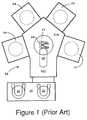
- Figure 1illustrates an existing wafer handling system 20 that allows a robot 21 to supply wafers to any of a plurality of IC processing chambers.
- Robot 21includes an extensible arm 28 that can extend a wafer blade 29 radially into any of chambers 23-27. Arm 28 is mounted on a rotatable table 210 that enables the extensible arm to be directed at any selected one of chambers 23-27.
- a vacuumis maintained in chamber 211 containing the robot so that the chambers 24-27 and 211 can be carefully cleaned and purged before wafers are introduced for processing.
- This systemenables wafers 22 to be exchanged between a wafer cassette elevator 23 and any of the chambers 24-27 without breaking vacuum in these chambers.
- Rotatable table 210 and robot 21are each coupled to motors exterior to chamber 211 to prevent wafers from being contaminated by operation of such motors.
- These motorsare typically in an atmospheric environment, so rotary seals are required to separate chamber 211 from the environment in which the motors are contained. These seals enable the motor shafts to extend between the motor and robot chambers while preserving the pressure difference between these chambers.
- Coupler 30consists of an outer assembly 31, a vacuum assembly 38 and an inner assembly 313.
- Outer assembly 31includes a cylindrical casing 32, a bottom cap 33 and a top cap 34.
- Casing 32encloses a chamber 35 and has attached to its inner wall a set of six bar magnets 36 polarized in the radial direction of casing 32.
- Bottom cap 33includes a ball bearing ring 37 into which can be fitted vacuum assembly 38.
- Vacuum assembly 38includes a flange 39 and a cylindrical shell 310 enclosing an inner cavity 311.
- wall 40(see Figure 3) between chamber 41 containing motor 42 and chamber 211 containing the robot contains a hole of diameter slightly larger than the outer diameter of cylindrical shell 310.
- a vacuum ring 43(see Figure 3) is slipped over cylindrical shell 310 which is then inserted through this hole in the wall and attached to the wall by flange bolts through range 39 with sufficient pressure against the vacuum ring to maintain the pressure difference between the motor and robot chambers.
- Inner assembly 313includes a ferrite inner pole section 314 having a set of six poles 315. On one end of section 314 is a ball bearing ring 316 and on the other end is a shaft 317 over which is slipped a ball bearing ring 318. When this inner assembly is inserted into inner cavity 311, ball bearing rings 316 and 318 cooperate to center shaft 317 and inner pole section 314 within cavity 311 and to enable inner pole section 314 and shaft 317 to rotate easy within this cavity. Shaft 317 is then connected to the robot to activate various operations of that robot.
- Outer assembly 31is slipped over shell 310 until shell 310 fits into ball bearing ring 37.
- Ball bearing rings 37, 316 and 318enable both inner assembly 313 and outer assembly 31 to rotate relative to vacuum assembly 38.
- a motoris connected to outer assembly 31 to controllably rotate that assembly relative to the vacuum assembly.
- Pole magnets 36 within outer assembly 36each magnetically couple to an associated pole 315 of ferrite inner pole section 314 so that the inner assembly rotates with the outer assembly.
- This magnetic couplerenables elimination of the rotary seals, but exhibits several deficiencies.
- the structure of the couplingshould be such that the vertical position of the robot does not vary when a vacuum is established in the robot chamber. Such variation could produce misalignment of a robot blade with a wafer in a chamber external to chamber 211.
- EP-A-0 160 305a device is disclosed comprising a first arm rotatably attached at one end thereof to a support base, a second arm rotatably attached to the other end of the first arm.
- the only function of the support base of such a deviceis to carry the arms.
- the problem described concerning the effects of the vacuum, however,is not solved by the device of EP-A-0 160 305.
- the apparatus of the inventioncomprises the features of claim 1.
- the motor chamberextends upward into the robot chamber so that the magnets that are attached directly to a motor are inside of the portion of the magnetic coupling that is within the robot chamber. This enables the side wall of the motor chamber to extend entirely through the robot chamber and provide support to both the top and bottom walls of the robot chamber.
- Figure 3illustrates a problem that occurs in a robot system, in which the drive motor 42 directly attaches to magnets that are outside of the inner pole section 314 that is attached directly to robot 44.
- inner pole section 314couples to a robot 44 having a wafer blade 45 that is to controllably extend through a wafer exchange slot 46 in sidewall 47 of robot chamber 211 to transfer wafers into and out of chamber 21 1.
- a vacuumis created in chamber 211 this bows wall 40 inward producing a vertical displacement of blade 45 upward relative to wafers in other chambers of a wafer handling systems such as shown in Figure 1.
- outer assembly 31which is directly attached to motor 42, is at a greater distance from the motor rotation axes than is inner pole section 314, which is attached directly to robot 44, this outer assembly 31 cannot be extended upward through chamber 211 without interfering with the operation of robot 44.
- motor chamber 41extended upward into the robot chamber and the power coupled from inside the motor chamber outward across the sidewall of the motor chamber into the robot chamber (instead of from outside inward as in Figure 3), then the motor chamber sidewall could extend from the bottom wall of the robot chamber to the top wall of robot chamber.
- the sidewall of the motor chamberprevents the bottom wall of the robot chamber from bowing upward and displacing the robot vertically relative to wafers in other chambers of the wafer handling system. Also, the motor chamber is accessible from above, thereby simplifying repair or replacement of parts within the motor chamber.
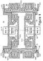
- Figure 4illustrates a magnetic coupler suitable for magnetically coupling one or more motors 51 and 52 from a cylindrical motor chamber 53 into a second chamber 54 that radially encircles the cylindrical motor chamber 53.
- a sidewall 55defines the radial extent of motor chamber 53 and enables a pressure difference to exist between chambers 53 and 54.
- Chamber 54is a robot vacuum chamber in which is contained a robot that is to transfer wafers to and from a set of reaction chambers disposed circumferentially around the robot. Selection of one of these chambers for wafer transfer is achieved by rotation of the robot. Transfer of a wafer into or out of the selected chamber is achieved by linear, radial extension of a robot arm into and out of the selected chamber.
- Motor 51is coupled to a reduction gear 513 to reduce the rotation speed of a typical motor to a rotation of gear output shaft 514 more appropriate for providing power to the robot.
- Reduction gear output shaft 514is attached to a magnet clamp 515 that presses against a bearing 516 and that holds a set of sixteen magnets 517, each of which is closely space from sidewall 55.
- motor 52is connected through a reduction gear 518 and a gear output shaft 519 to a magnet clamp 520 that presses against a bearing 521 and that holds a set of sixteen magnets 522.
- a magnet clamp 520that presses against a bearing 521 and that holds a set of sixteen magnets 522.
- Bolted to this magnet clamp above and below the magnetsare a pair of magnet retainer rings that prevent vertical motion of these magnets.
- Robot vacuum chamber 54is enclosed by cylindrical inner wall 55, top wall 523 and bottom wall 524 continuing in an outer wall (not shown). A vacuum seal of chamber 54 is created by vacuum rings 525 and 526.
- a magnet clamp 528that is similar to clamps 515 and 520, except that the fingers extend radially inward. Magnet retainer rings above and below the magnets are bolted to clamp 528 to retain these magnets vertically.
- a similar set of magnet clamp 529 and retainer rings 30hold a set of 16 magnets 530.
- a set of bearings 531 - 534enable clamps 528 and 529 to rotate about motor axis A.
- Figure 5illustrates an alternate embodiment of providing additional support between a top wall 1001 and a bottom wall 1002 of the robot chamber 1003.
- This "additional" supportis in addition to support by sidewall 1004.
- the additional supportis provided by a rotatable shaft 1005.
- the robotconsists of motor 1010, thrust bearings 1006 and 1007, and wafer blade.
- This robothas the single degree of freedom to rotate a wafer 1009 to any selected angular position about shaft 1005.
- Thrust bearings 1006 and 1007enable shaft 1005 to rotate even though shaft 1005 is compressed by a force equal to twice the atmospheric pressure on top wall 1001.
- motor 1010is anchored to bottom wall 1002 by support 1011 and thrust bearing 1007 is located within motor 1010.
- wall 55should be selected to be conductive so that eddy currents therein are produced to damp such oscillations.
- This wallcan be coated with a conductive coating to enhance these eddy currents, but preferably wall 55 is of a conductive material such as aluminum so that bulk eddy currents can be generated.
Landscapes
- Engineering & Computer Science (AREA)
- Robotics (AREA)
- Mechanical Engineering (AREA)
- Physics & Mathematics (AREA)
- Condensed Matter Physics & Semiconductors (AREA)
- General Physics & Mathematics (AREA)
- Manufacturing & Machinery (AREA)
- Computer Hardware Design (AREA)
- Microelectronics & Electronic Packaging (AREA)
- Power Engineering (AREA)
- Manipulator (AREA)
- Container, Conveyance, Adherence, Positioning, Of Wafer (AREA)
Description
- This invention relates to a robot apparatus especially foruse in integrated circuit production.
- Figure 1 illustrates an existing
wafer handling system 20that allows arobot 21 to supply wafers to any of aplurality of IC processing chambers.Robot 21 includes anextensible arm 28 that can extend awafer blade 29 radiallyinto any of chambers 23-27.Arm 28 is mounted on arotatable table 210 that enables the extensible arm to bedirected at any selected one of chambers 23-27. A vacuum ismaintained inchamber 211 containing the robot so that thechambers 24-27 and 211 can be carefully cleaned and purgedbefore wafers are introduced for processing. This systemenableswafers 22 to be exchanged between awafer cassetteelevator 23 and any of the chambers 24-27 without breakingvacuum in these chambers. - Rotatable table 210 and
robot 21 are each coupled to motorsexterior tochamber 211 to prevent wafers from beingcontaminated by operation of such motors. These motors aretypically in an atmospheric environment, so rotary sealsare required to separatechamber 211 from the environmentin which the motors are contained. These seals enable themotor shafts to extend between the motor and robot chamberswhile preserving the pressure difference between thesechambers. - In a robot system manufactured by Anelva, these rotaryseals are replaced by a
magnetic coupler 30 illustrated inFigure 2.Coupler 30 consists of anouter assembly 31, avacuum assembly 38 and aninner assembly 313. Outer assembly 31 includes acylindrical casing 32, abottom cap 33 and atop cap 34. Casing 32 encloses achamber 35 and has attached to its inner wall a set of sixbar magnets 36 polarized in the radial direction ofcasing 32.Bottom cap 33 includes a ball bearingring 37 intowhich can be fittedvacuum assembly 38.Vacuum assembly 38 includes aflange 39 and acylindricalshell 310 enclosing aninner cavity 311. In an integratedcircuit processing system using a robot such as that shownin Figure 1, wall 40 (see Figure 3) betweenchamber 41containingmotor 42 andchamber 211 containing the robotcontains a hole of diameter slightly larger than the outerdiameter ofcylindrical shell 310. A vacuum ring 43 (seeFigure 3) is slipped overcylindrical shell 310 which isthen inserted through this hole in the wall and attached tothe wall by flange bolts throughrange 39 with sufficientpressure against the vacuum ring to maintain the pressuredifference between the motor and robot chambers.Inner assembly 313 includes a ferriteinner pole section 314 having a set of sixpoles 315. On one end ofsection 314 is a ball bearingring 316 and on the other end is ashaft 317 over which is slipped a ball bearing ring 318.When this inner assembly is inserted intoinner cavity 311,ball bearingrings 316 and 318 cooperate to center shaft317 andinner pole section 314 withincavity 311 and toenableinner pole section 314 and shaft 317 to rotate easywithin this cavity. Shaft 317 is then connected to therobot to activate various operations of that robot.Outer assembly 31 is slipped overshell 310 untilshell 310fits into ball bearingring 37.Ball bearing rings inner assembly 313 andouter assembly 31 to rotate relative tovacuum assembly 38. A motor isconnected toouter assembly 31 to controllably rotate thatassembly relative to the vacuum assembly.Pole magnets 36withinouter assembly 36 each magnetically couple to anassociatedpole 315 of ferriteinner pole section 314 sothat the inner assembly rotates with the outer assembly.- This magnetic coupler enables elimination of the rotaryseals, but exhibits several deficiencies. In particular,the structure of the coupling should be such that thevertical position of the robot does not vary when a vacuumis established in the robot chamber. Such variation couldproduce misalignment of a robot blade with a wafer in achamber external to
chamber 211. - In EP-A-0 160 305 a device is disclosed comprising a firstarm rotatably attached at one end thereof to a supportbase, a second arm rotatably attached to the other end ofthe first arm. The only function of the support base ofsuch a device is to carry the arms. The problem describedconcerning the effects of the vacuum, however, is notsolved by the device of EP-A-0 160 305.
- It is the object of the invention to provide an apparatusespecially for use in integrated circuit production, havingarranged a robot within a vacuum chamber, the positions of said robot being maintained unchanged within that chamberupon application of a vacuum.
- The apparatus of the invention comprises the features ofclaim 1.
- With the specific embodiment, the motor chamber extendsupward into the robot chamber so that the magnets that areattached directly to a motor are inside of the portion ofthe magnetic coupling that is within the robot chamber.This enables the side wall of the motor chamber to extendentirely through the robot chamber and provide support toboth the top and bottom walls of the robot chamber. Theutility of this can be understood by reference to Figure 3.
- Figure 3 illustrates a problem that occurs in a robotsystem, in which the
drive motor 42 directly attaches tomagnets that are outside of theinner pole section 314 thatis attached directly torobot 44. In this illustratedembodiment,inner pole section 314 couples to arobot 44having awafer blade 45 that is to controllably extendthrough awafer exchange slot 46 insidewall 47 ofrobotchamber 211 to transfer wafers into and out ofchamber 211. When a vacuum is created inchamber 211 thisbows wall 40 inward producing a vertical displacement ofblade 45upward relative to wafers in other chambers of a waferhandling systems such as shown in Figure 1. Becauseouterassembly 31, which is directly attached tomotor 42, is ata greater distance from the motor rotation axes than isinner pole section 314, which is attached directly torobot 44, thisouter assembly 31 cannot be extended upwardthroughchamber 211 without interfering with the operationofrobot 44. However, ifmotor chamber 41 extended upwardinto the robot chamber and the power coupled from insidethe motor chamber outward across the sidewall of the motorchamber into the robot chamber (instead of from outside inward as in Figure 3), then the motor chamber sidewallcould extend from the bottom wall of the robot chamber tothe top wall of robot chamber. For such a configuration,when a vacuum is produced in the robot chamber, thesidewall of the motor chamber prevents the bottom wall ofthe robot chamber from bowing upward and displacing therobot vertically relative to wafers in other chambers ofthe wafer handling system. Also, the motor chamber isaccessible from above, thereby simplifying repair orreplacement of parts within the motor chamber. - Figure 1
- illustrates a
wafer handling system 20 thatallows arobot 21 to supply wafers to any of aplurality of IC processing chambers. - Figure 2
- illustrates the components of a magnetic couplerutilized in a robot manufactured by Anelva.
- Figure 3
- illustrates an integrated circuit processingsystem utilizing the magnetic coupler of Figure 2.
- Figure 4
- illustrates a magnetic coupler for magneticallycoupling rotational motion from one or moremotors in a motor chamber into another chambersurrounding the motor chamber.
- Figure 5
- illustrates an alternate embodiment in whichadditional support is provided between the topand bottom walls of a robot vacuum chamber tosubstantially eliminate vertical displacement ofa robot when vacuum is produced within this chamber.
- Figure 4 illustrates a magnetic coupler suitable formagnetically coupling one or
more motors cylindrical motor chamber 53 into asecond chamber 54 thatradially encircles thecylindrical motor chamber 53. Asidewall 55 defines the radial extent ofmotor chamber 53and enables a pressure difference to exist betweenchambers Chamber 54 is a robot vacuum chamber in which iscontained a robot that is to transfer wafers to and from aset of reaction chambers disposed circumferentially aroundthe robot. Selection of one of these chambers for wafertransfer is achieved by rotation of the robot. Transfer ofa wafer into or out of the selected chamber is achieved bylinear, radial extension of a robot arm into and out of theselected chamber. Motor 51 is coupled to areduction gear 513 to reduce therotation speed of a typical motor to a rotation ofgearoutput shaft 514 more appropriate for providing power tothe robot. Reductiongear output shaft 514 is attached to amagnet clamp 515 that presses against abearing 516 andthat holds a set of sixteenmagnets 517, each of which isclosely space from sidewall 55.- Similarly,
motor 52 is connected through areduction gear 518 and agear output shaft 519 to amagnet clamp 520 thatpresses against abearing 521 and that holds a set ofsixteenmagnets 522. Bolted to this magnet clamp above andbelow the magnets are a pair of magnet retainer rings thatprevent vertical motion of these magnets. Robot vacuum chamber 54 is enclosed by cylindrical innerwall 55,top wall 523 andbottom wall 524 continuing in an outer wall (not shown). A vacuum seal ofchamber 54 iscreated by vacuum rings 525 and 526. Withinrobot chamber 54 are a set of sixteenmagnets 527 retained within theplane of the magnets by amagnet clamp 528 that is similartoclamps magnet clamp 529 and retainerrings 30 hold a set of 16 magnets 530. A set of bearings531 - 534 enable clamps 528 and 529 to rotate about motoraxis A.- Because side wall 55 extends between
top wall 523 andbottom wall 524, when a vacuum is produced withinchamber 54, there is no vertical displacement of robot blade 45(Fig. 3) with respect to wafer rest positions withinexternal chambers, thereby maintaining alignment of waferblade 86 with wafers external to the robot vacuum chamberfor any range of internal pressures withincavity 54. - Figure 5 illustrates an alternate embodiment of providingadditional support between a
top wall 1001 and abottomwall 1002 of therobot chamber 1003. This "additional"support is in addition to support bysidewall 1004. In thisembodiment, the additional support is provided by arotatable shaft 1005. In this embodiment, the robotconsists ofmotor 1010, thrustbearings wafer 1009 to any selected angularposition aboutshaft 1005.Thrust bearings shaft 1005 to rotate even thoughshaft 1005 iscompressed by a force equal to twice the atmosphericpressure ontop wall 1001. In an alternate of thisembodiment,motor 1010 is anchored tobottom wall 1002 bysupport 1011 and thrustbearing 1007 is located withinmotor 1010. - To dampen oscillations in the robot during rotation orblade extension, wall 55 should be selected to beconductive so that eddy currents therein are produced todamp such oscillations. This wall can be coated with aconductive coating to enhance these eddy currents, butpreferably wall 55 is of a conductive material such asaluminum so that bulk eddy currents can be generated.
- Further details about the design and arrangement of therobot are disclosed in EP-A-0423608 which is the parentapplication for the present application.
Claims (5)
- A robot apparatus comprising:a robot vacuum chamber (54, 1003) having an outerwall (1104), a top wall (523, 1001) and a bottom wall (524,1002);a robot (80, 1008) within said vacuum chamber (54,1003); anda support (55, 1005, 1006, 1007) within said vacuumchamber
characterized in thatsaid support (55, 1005, 1006, 1007) within saidvacuum chamber (54, 1003) is extending from the top wall(523, 1001) to the bottom wall (524, 1002), whereby when avacuum is produced within said vacuum chamber (54, 1003),said support (55, 1005, 1006, 1007) significantly reducesvertical displacement of said top and bottom walls (523,1001; 534, 1002) by ambient pressure; andsaid robot (80, 1008) is attached to said support(1005, 1006); - A robot apparatus according to claim 1,
wherein said support comprises a cylindrical wall (55)extending between the top and bottom walls (523, 524) ofthe vacuum chamber. - A robot apparatus according to claim 2,
wherein said cylindrical wall (55) is a wall enclosing amotor chamber (53) of the robot (80). - A robot apparatus according to claim 1,
wherein said support comprises a rotatable shaft (1005) anda thrust bearing (1006, 1007) between an end of said shaft(1005) an the top or bottom wall (1001, 1002) of saidvacuum chamber (1003). - A robot apparatus according to claim 4,
wherein a motor (1010) driving said shaft is anchored tosaid top or bottom wall and said thrust bearing (1007) islocated within said motor (1010).
Priority Applications (1)
| Application Number | Priority Date | Filing Date | Title |
|---|---|---|---|
| EP98106428AEP0858867A3 (en) | 1989-10-20 | 1990-10-10 | Robot apparatus |
Applications Claiming Priority (3)
| Application Number | Priority Date | Filing Date | Title |
|---|---|---|---|
| US42477189A | 1989-10-20 | 1989-10-20 | |
| US424771 | 1989-10-20 | ||
| EP90119433AEP0423608B1 (en) | 1989-10-20 | 1990-10-10 | Two-axis magnetically coupled robot |
Related Parent Applications (2)
| Application Number | Title | Priority Date | Filing Date |
|---|---|---|---|
| EP90119433ADivisionEP0423608B1 (en) | 1989-10-20 | 1990-10-10 | Two-axis magnetically coupled robot |
| EP90119433.2Division | 1990-10-10 |
Related Child Applications (1)
| Application Number | Title | Priority Date | Filing Date |
|---|---|---|---|
| EP98106428ADivisionEP0858867A3 (en) | 1989-10-20 | 1990-10-10 | Robot apparatus |
Publications (3)
| Publication Number | Publication Date |
|---|---|
| EP0600851A2 EP0600851A2 (en) | 1994-06-08 |
| EP0600851A3 EP0600851A3 (en) | 1994-08-17 |
| EP0600851B1true EP0600851B1 (en) | 1999-02-03 |
Family
ID=23683794
Family Applications (3)
| Application Number | Title | Priority Date | Filing Date |
|---|---|---|---|
| EP94101717AExpired - LifetimeEP0600851B1 (en) | 1989-10-20 | 1990-10-10 | Robot apparatus |
| EP98106428AWithdrawnEP0858867A3 (en) | 1989-10-20 | 1990-10-10 | Robot apparatus |
| EP90119433AExpired - LifetimeEP0423608B1 (en) | 1989-10-20 | 1990-10-10 | Two-axis magnetically coupled robot |
Family Applications After (2)
| Application Number | Title | Priority Date | Filing Date |
|---|---|---|---|
| EP98106428AWithdrawnEP0858867A3 (en) | 1989-10-20 | 1990-10-10 | Robot apparatus |
| EP90119433AExpired - LifetimeEP0423608B1 (en) | 1989-10-20 | 1990-10-10 | Two-axis magnetically coupled robot |
Country Status (6)
| Country | Link |
|---|---|
| US (5) | US5583408A (en) |
| EP (3) | EP0600851B1 (en) |
| JP (1) | JPH0755464B2 (en) |
| KR (1) | KR100204161B1 (en) |
| DE (2) | DE69032945T2 (en) |
| ES (2) | ES2090074T3 (en) |
Families Citing this family (129)
| Publication number | Priority date | Publication date | Assignee | Title |
|---|---|---|---|---|
| US5447409A (en)* | 1989-10-20 | 1995-09-05 | Applied Materials, Inc. | Robot assembly |
| EP0600851B1 (en)* | 1989-10-20 | 1999-02-03 | Applied Materials, Inc. | Robot apparatus |
| CH684686A5 (en)* | 1991-10-24 | 1994-11-30 | Rico Ursin Ruffner | Robot with direct drive system. |
| JP2598353B2 (en)* | 1991-12-04 | 1997-04-09 | アネルバ株式会社 | Substrate processing device, substrate transfer device, and substrate replacement method |
| JPH0773833B2 (en)* | 1992-04-23 | 1995-08-09 | アプライド マテリアルズ インコーポレイテッド | Robot assembly |
| US5376862A (en)* | 1993-01-28 | 1994-12-27 | Applied Materials, Inc. | Dual coaxial magnetic couplers for vacuum chamber robot assembly |
| CN1046654C (en)* | 1993-04-16 | 1999-11-24 | 布鲁克斯自动化公司 | Articulated arm transfer device |
| EP0634784A1 (en)* | 1993-07-16 | 1995-01-18 | Applied Materials, Inc. | Variable speed wafer exchange robot |
| US5647724A (en)* | 1995-10-27 | 1997-07-15 | Brooks Automation Inc. | Substrate transport apparatus with dual substrate holders |
| US6481956B1 (en) | 1995-10-27 | 2002-11-19 | Brooks Automation Inc. | Method of transferring substrates with two different substrate holding end effectors |
| US6299404B1 (en)* | 1995-10-27 | 2001-10-09 | Brooks Automation Inc. | Substrate transport apparatus with double substrate holders |
| US6065858A (en)* | 1995-12-20 | 2000-05-23 | Fujitsu Limited | Milling machine and methods of milling and menu selection |
| JP3740770B2 (en)* | 1995-12-28 | 2006-02-01 | 日本精工株式会社 | Sealed actuator |
| TW349897B (en)* | 1996-02-02 | 1999-01-11 | Komatsu Mfg Co Ltd | Operational robot |
| US6102164A (en)* | 1996-02-28 | 2000-08-15 | Applied Materials, Inc. | Multiple independent robot assembly and apparatus for processing and transferring semiconductor wafers |
| US20040005211A1 (en)* | 1996-02-28 | 2004-01-08 | Lowrance Robert B. | Multiple independent robot assembly and apparatus and control system for processing and transferring semiconductor wafers |
| EP0891840A4 (en)* | 1996-03-18 | 2000-01-19 | Komatsu Mfg Co Ltd | Control device for a work carrying system |
| EP0960696A4 (en)* | 1996-03-22 | 2000-02-02 | Komatsu Mfg Co Ltd | Robot for handling |
| US6062798A (en)* | 1996-06-13 | 2000-05-16 | Brooks Automation, Inc. | Multi-level substrate processing apparatus |
| US5911834A (en)* | 1996-11-18 | 1999-06-15 | Applied Materials, Inc. | Gas delivery system |
| US5844195A (en)* | 1996-11-18 | 1998-12-01 | Applied Materials, Inc. | Remote plasma source |
| US5855681A (en)* | 1996-11-18 | 1999-01-05 | Applied Materials, Inc. | Ultra high throughput wafer vacuum processing system |
| US5838121A (en)* | 1996-11-18 | 1998-11-17 | Applied Materials, Inc. | Dual blade robot |
| US5961269A (en) | 1996-11-18 | 1999-10-05 | Applied Materials, Inc. | Three chamber load lock apparatus |
| US5905302A (en)* | 1996-11-18 | 1999-05-18 | Applied Materials, Inc. | Loadlock cassette with wafer support rails |
| US5902088A (en)* | 1996-11-18 | 1999-05-11 | Applied Materials, Inc. | Single loadlock chamber with wafer cooling function |
| US6077157A (en)* | 1996-11-18 | 2000-06-20 | Applied Materials, Inc. | Process chamber exhaust system |
| US6152070A (en) | 1996-11-18 | 2000-11-28 | Applied Materials, Inc. | Tandem process chamber |
| US5909994A (en)* | 1996-11-18 | 1999-06-08 | Applied Materials, Inc. | Vertical dual loadlock chamber |
| US6224312B1 (en) | 1996-11-18 | 2001-05-01 | Applied Materials, Inc. | Optimal trajectory robot motion |
| US6082950A (en)* | 1996-11-18 | 2000-07-04 | Applied Materials, Inc. | Front end wafer staging with wafer cassette turntables and on-the-fly wafer center finding |
| US5955858A (en)* | 1997-02-14 | 1999-09-21 | Applied Materials, Inc. | Mechanically clamping robot wrist |
| JP3757016B2 (en)* | 1997-02-20 | 2006-03-22 | ローツェ株式会社 | Handling robot |
| US6432203B1 (en)* | 1997-03-17 | 2002-08-13 | Applied Komatsu Technology, Inc. | Heated and cooled vacuum chamber shield |
| US6129704A (en) | 1997-06-12 | 2000-10-10 | Schneider (Usa) Inc. | Perfusion balloon catheter having a magnetically driven impeller |
| US6155773A (en)* | 1997-09-22 | 2000-12-05 | Applied Materials, Inc. | Substrate clamping apparatus |
| US6071055A (en)* | 1997-09-30 | 2000-06-06 | Applied Materials, Inc. | Front end vacuum processing environment |
| US6235634B1 (en) | 1997-10-08 | 2001-05-22 | Applied Komatsu Technology, Inc. | Modular substrate processing system |
| US6688375B1 (en) | 1997-10-14 | 2004-02-10 | Applied Materials, Inc. | Vacuum processing system having improved substrate heating and cooling |
| JPH11176822A (en)* | 1997-12-05 | 1999-07-02 | Hitachi Ltd | Semiconductor processing equipment |
| US6169933B1 (en) | 1998-04-23 | 2001-01-02 | Sandia Corporation | Method and apparatus for monitoring plasma processing operations |
| US6275740B1 (en) | 1998-04-23 | 2001-08-14 | Sandia Corporation | Method and apparatus for monitoring plasma processing operations |
| US6246473B1 (en) | 1998-04-23 | 2001-06-12 | Sandia Corporation | Method and apparatus for monitoring plasma processing operations |
| US6254717B1 (en) | 1998-04-23 | 2001-07-03 | Sandia Corporation | Method and apparatus for monitoring plasma processing operations |
| US6077386A (en)* | 1998-04-23 | 2000-06-20 | Sandia Corporation | Method and apparatus for monitoring plasma processing operations |
| US6419801B1 (en) | 1998-04-23 | 2002-07-16 | Sandia Corporation | Method and apparatus for monitoring plasma processing operations |
| US6090302A (en)* | 1998-04-23 | 2000-07-18 | Sandia | Method and apparatus for monitoring plasma processing operations |
| US6223755B1 (en) | 1998-04-23 | 2001-05-01 | Sandia Corporation | Method and apparatus for monitoring plasma processing operations |
| US6132577A (en)* | 1998-04-23 | 2000-10-17 | Sandia Corporation | Method and apparatus for monitoring plasma processing operations |
| US6269278B1 (en) | 1998-04-23 | 2001-07-31 | Sandia Corporation | Method and apparatus for monitoring plasma processing operations |
| US6165312A (en)* | 1998-04-23 | 2000-12-26 | Sandia Corporation | Method and apparatus for monitoring plasma processing operations |
| US6221679B1 (en)* | 1998-04-23 | 2001-04-24 | Sandia Corporation | Method and apparatus for monitoring plasma processing operations |
| US6123983A (en)* | 1998-04-23 | 2000-09-26 | Sandia Corporation | Method and apparatus for monitoring plasma processing operations |
| US6261470B1 (en) | 1998-04-23 | 2001-07-17 | Sandia Corporation | Method and apparatus for monitoring plasma processing operations |
| US6134005A (en)* | 1998-04-23 | 2000-10-17 | Sandia Corporation | Method and apparatus for monitoring plasma processing operations |
| US6192826B1 (en) | 1998-04-23 | 2001-02-27 | Sandia Corporation | Method and apparatus for monitoring plasma processing operations |
| US6157447A (en)* | 1998-04-23 | 2000-12-05 | Sandia Corporation | Method and apparatus for monitoring plasma processing operations |
| US6213704B1 (en) | 1998-05-20 | 2001-04-10 | Applied Komatsu Technology, Inc. | Method and apparatus for substrate transfer and processing |
| US6086362A (en) | 1998-05-20 | 2000-07-11 | Applied Komatsu Technology, Inc. | Multi-function chamber for a substrate processing system |
| US6176668B1 (en) | 1998-05-20 | 2001-01-23 | Applied Komatsu Technology, Inc. | In-situ substrate transfer shuttle |
| US6215897B1 (en) | 1998-05-20 | 2001-04-10 | Applied Komatsu Technology, Inc. | Automated substrate processing system |
| US6206176B1 (en) | 1998-05-20 | 2001-03-27 | Applied Komatsu Technology, Inc. | Substrate transfer shuttle having a magnetic drive |
| US6517303B1 (en) | 1998-05-20 | 2003-02-11 | Applied Komatsu Technology, Inc. | Substrate transfer shuttle |
| US6224319B1 (en) | 1998-07-10 | 2001-05-01 | Equibe Technologies | Material handling device with overcenter arms and method for use thereof |
| US6247889B1 (en) | 1998-07-31 | 2001-06-19 | Bks Lab. Ltd. | Multiple-shaft power transmission apparatus and wafer transport arm link |
| US6217272B1 (en) | 1998-10-01 | 2001-04-17 | Applied Science And Technology, Inc. | In-line sputter deposition system |
| US6328858B1 (en) | 1998-10-01 | 2001-12-11 | Nexx Systems Packaging, Llc | Multi-layer sputter deposition apparatus |
| US6106634A (en)* | 1999-02-11 | 2000-08-22 | Applied Materials, Inc. | Methods and apparatus for reducing particle contamination during wafer transport |
| US6322312B1 (en) | 1999-03-18 | 2001-11-27 | Applied Materials, Inc. | Mechanical gripper for wafer handling robots |
| TW543079B (en)* | 1999-06-03 | 2003-07-21 | Applied Materials Inc | Robot blade for semiconductor processing equipment |
| US6513848B1 (en) | 1999-09-17 | 2003-02-04 | Applied Materials, Inc. | Hydraulically actuated wafer clamp |
| US6298685B1 (en) | 1999-11-03 | 2001-10-09 | Applied Materials, Inc. | Consecutive deposition system |
| US6949143B1 (en)* | 1999-12-15 | 2005-09-27 | Applied Materials, Inc. | Dual substrate loadlock process equipment |
| US6537011B1 (en) | 2000-03-10 | 2003-03-25 | Applied Materials, Inc. | Method and apparatus for transferring and supporting a substrate |
| US6530733B2 (en) | 2000-07-27 | 2003-03-11 | Nexx Systems Packaging, Llc | Substrate processing pallet and related substrate processing method and machine |
| US6821912B2 (en) | 2000-07-27 | 2004-11-23 | Nexx Systems Packaging, Llc | Substrate processing pallet and related substrate processing method and machine |
| US6682288B2 (en) | 2000-07-27 | 2004-01-27 | Nexx Systems Packaging, Llc | Substrate processing pallet and related substrate processing method and machine |
| WO2002023597A2 (en) | 2000-09-15 | 2002-03-21 | Applied Materials, Inc. | Double dual slot load lock for process equipment |
| US6817640B2 (en)* | 2001-06-28 | 2004-11-16 | Applied Materials, Inc. | Four-bar linkage wafer clamping mechanism |
| US6591850B2 (en)* | 2001-06-29 | 2003-07-15 | Applied Materials, Inc. | Method and apparatus for fluid flow control |
| US7316966B2 (en) | 2001-09-21 | 2008-01-08 | Applied Materials, Inc. | Method for transferring substrates in a load lock chamber |
| US6682113B2 (en) | 2001-11-16 | 2004-01-27 | Applied Materials, Inc. | Wafer clamping mechanism |
| US6670807B2 (en)* | 2002-01-16 | 2003-12-30 | Applied Materials, Inc. | Proximity sensor detecting loss of magnetic field complete |
| US7458914B2 (en) | 2002-03-29 | 2008-12-02 | Matsushita Electric Industrial Co., Ltd. | Method and apparatus for a low cost and high force transmission using elastically deformable driving element for friction drive |
| KR100555683B1 (en)* | 2003-01-27 | 2006-03-03 | 조만수 | Supplements for Health Supplements based on Herbal Medicines and Manufacturing Method Thereof |
| US7077973B2 (en) | 2003-04-18 | 2006-07-18 | Applied Materials, Inc. | Methods for substrate orientation |
| US7226512B2 (en)* | 2003-06-18 | 2007-06-05 | Ekc Technology, Inc. | Load lock system for supercritical fluid cleaning |
| US7100954B2 (en) | 2003-07-11 | 2006-09-05 | Nexx Systems, Inc. | Ultra-thin wafer handling system |
| US7207766B2 (en) | 2003-10-20 | 2007-04-24 | Applied Materials, Inc. | Load lock chamber for large area substrate processing system |
| US7128806B2 (en) | 2003-10-21 | 2006-10-31 | Applied Materials, Inc. | Mask etch processing apparatus |
| US20050133166A1 (en)* | 2003-12-19 | 2005-06-23 | Applied Materials, Inc. | Tuned potential pedestal for mask etch processing apparatus |
| US20050133158A1 (en)* | 2003-12-19 | 2005-06-23 | Applied Materials, Inc. | Mask handler apparatus |
| JP2005286102A (en)* | 2004-03-30 | 2005-10-13 | Hitachi High-Technologies Corp | Vacuum processing apparatus and vacuum processing method |
| US7384228B2 (en)* | 2004-05-24 | 2008-06-10 | Asml Netherlands B.V. | Insertion device, lithographic apparatus with said insertion device and device manufacturing method |
| US7497414B2 (en) | 2004-06-14 | 2009-03-03 | Applied Materials, Inc. | Curved slit valve door with flexible coupling |
| JP2008521261A (en)* | 2004-11-22 | 2008-06-19 | アプライド マテリアルズ インコーポレイテッド | Substrate processing apparatus using batch processing chamber |
| US20070196011A1 (en)* | 2004-11-22 | 2007-08-23 | Cox Damon K | Integrated vacuum metrology for cluster tool |
| US7290813B2 (en)* | 2004-12-16 | 2007-11-06 | Asyst Technologies, Inc. | Active edge grip rest pad |
| JP4233520B2 (en)* | 2004-12-28 | 2009-03-04 | ローツェ株式会社 | Handling robot |
| JP4581757B2 (en)* | 2005-03-11 | 2010-11-17 | 日本精工株式会社 | Motor system |
| JP4580845B2 (en)* | 2005-08-24 | 2010-11-17 | パナソニック株式会社 | Task execution device |
| US7845891B2 (en) | 2006-01-13 | 2010-12-07 | Applied Materials, Inc. | Decoupled chamber body |
| US7665951B2 (en) | 2006-06-02 | 2010-02-23 | Applied Materials, Inc. | Multiple slot load lock chamber and method of operation |
| US7845618B2 (en) | 2006-06-28 | 2010-12-07 | Applied Materials, Inc. | Valve door with ball coupling |
| US8124907B2 (en) | 2006-08-04 | 2012-02-28 | Applied Materials, Inc. | Load lock chamber with decoupled slit valve door seal compartment |
| TW200900210A (en)* | 2006-11-09 | 2009-01-01 | Ihi Corp | Frog-leg arm robot and control method thereof |
| US7695080B2 (en)* | 2007-06-05 | 2010-04-13 | King Slide Works Co., Ltd. | Securing device for a drawer slide |
| US9752615B2 (en)* | 2007-06-27 | 2017-09-05 | Brooks Automation, Inc. | Reduced-complexity self-bearing brushless DC motor |
| KR101660894B1 (en) | 2007-06-27 | 2016-10-10 | 브룩스 오토메이션 인코퍼레이티드 | Multiple dimension position sensor |
| CN101790673B (en) | 2007-06-27 | 2013-08-28 | 布鲁克斯自动化公司 | Position feedback for self-bearing motors |
| US8283813B2 (en) | 2007-06-27 | 2012-10-09 | Brooks Automation, Inc. | Robot drive with magnetic spindle bearings |
| KR101825595B1 (en) | 2007-07-17 | 2018-02-05 | 브룩스 오토메이션 인코퍼레이티드 | Substrate processing apparatus with motors integral to chamber walls |
| US7861540B2 (en)* | 2008-01-25 | 2011-01-04 | Hamilton Storage Technologies, Inc. | Automated storage and retrieval system for storing biological or chemical samples at ultra-low temperatures |
| CH699897A2 (en)* | 2008-11-10 | 2010-05-14 | Etel Sa | SCARA-type parallel robot. |
| US9273557B2 (en)* | 2011-02-17 | 2016-03-01 | Hitachi Metals, Ltd. | Motor device |
| JP2013096443A (en)* | 2011-10-28 | 2013-05-20 | Ulvac Japan Ltd | Rotation introducing machine, robot device and rotation introducing method |
| TW201434668A (en)* | 2013-03-14 | 2014-09-16 | Kinpo Elect Inc | Multi-function printer |
| KR102177156B1 (en) | 2014-03-10 | 2020-11-10 | 삼성전자주식회사 | robot and substrate processing apparatus including the same |
| DE102014009892B4 (en)* | 2014-07-04 | 2018-05-30 | gomtec GmbH | Drive unit with magnetic interface |
| KR101511258B1 (en) | 2014-07-08 | 2015-04-14 | (주)해피글로벌솔루션 | robot arm coupler device of a improved balance |
| JP6513508B2 (en)* | 2015-07-01 | 2019-05-15 | 東京エレクトロン株式会社 | Transport apparatus, control method therefor, and substrate processing system |
| CN108214452B (en)* | 2016-12-21 | 2020-09-15 | 深圳市肯綮科技有限公司 | Lower limb assistance exoskeleton device and power joint device thereof |
| CN107435700A (en)* | 2017-09-13 | 2017-12-05 | 东莞市思榕智能装备有限公司 | A new method of using power-off brakes in series |
| SG11202004931PA (en) | 2017-11-27 | 2020-06-29 | Murata Machinery Ltd | Storage device |
| US11561359B2 (en)* | 2018-02-09 | 2023-01-24 | Carl Zeiss Meditec Ag | Balancing device for rotary apparatus |
| TWI815869B (en) | 2018-03-16 | 2023-09-21 | 美商布魯克斯自動機械美國公司 | Substrate transport apparauts and method therefor |
| US12076859B2 (en) | 2020-10-14 | 2024-09-03 | Applied Materials, Inc. | Infinite rotation of vacuum robot linkage through timing belt with isolated environment |
| DE102023130797A1 (en)* | 2023-11-07 | 2025-05-08 | KyooBe Tech GmbH | Swivel unit |
| CN119601523A (en)* | 2024-10-23 | 2025-03-11 | 西北电子装备技术研究所(中国电子科技集团公司第二研究所) | A small dynamic sealing wafer grabbing and anti-collision device |
Family Cites Families (96)
| Publication number | Priority date | Publication date | Assignee | Title |
|---|---|---|---|---|
| US2722617A (en)* | 1951-11-28 | 1955-11-01 | Hartford Nat Bank & Trust Comp | Magnetic circuits and devices |
| US2993152A (en)* | 1957-07-18 | 1961-07-18 | Westinghouse Electric Corp | Shields for magnets |
| FR1187997A (en)* | 1959-01-20 | 1959-09-17 | Commissariat Energie Atomique | Magnetic transmission remote manipulator for manipulation inside sealed enclosures |
| US3523204A (en)* | 1968-01-19 | 1970-08-04 | Sydney Rand | Magnetic transmission system |
| JPS5122150B1 (en)* | 1970-12-31 | 1976-07-07 | ||
| US3799057A (en)* | 1972-01-26 | 1974-03-26 | Palmer Shile Co | Electrical control system |
| GB1489055A (en)* | 1973-08-17 | 1977-10-19 | Pont Res & Investment Services | Magnetic coupling |
| US3954191A (en)* | 1974-11-18 | 1976-05-04 | Extrion Corporation | Isolation lock for workpieces |
| US4163914A (en)* | 1977-04-11 | 1979-08-07 | Keyes John H | Infinitely variable ratio permanent magnet transmission |
| US4163164A (en)* | 1977-10-11 | 1979-07-31 | Micropump Corporation | Split magnet drive |
| US4215330A (en)* | 1977-12-20 | 1980-07-29 | Ethel Hartman | Permanent magnet propulsion system |
| JPS5656396A (en)* | 1979-10-12 | 1981-05-18 | Hiroshi Makino | Robot for assembly |
| DE3012740A1 (en)* | 1980-03-28 | 1981-10-08 | Siemens AG, 1000 Berlin und 8000 München | MAGNETIC CENTRAL TURNTABLE |
| US4379598A (en)* | 1980-12-22 | 1983-04-12 | North American Philips Corporation | Magnetic bearing |
| FR2499647B1 (en)* | 1981-02-06 | 1989-03-03 | Nova Scotia Res Found | IMPROVEMENTS ON HERMETIC MAGNETIC COUPLINGS |
| IT1144724B (en)* | 1981-06-03 | 1986-10-29 | Comau Spa | TWO-PIECE ARMS MANIPULATOR APPARATUS |
| JPS5843421A (en)* | 1981-09-09 | 1983-03-14 | Toshiba Corp | Optical deflector for rotary mirror |
| DE3141312A1 (en)* | 1981-10-17 | 1983-07-07 | Leybold-Heraeus GmbH, 5000 Köln | VACUUM ARC MELTING AND MOLDING OVEN WITH VACUUM CHAMBER AND TILTING JAR |
| US4424473A (en)* | 1982-02-05 | 1984-01-03 | American Robot Corporation | Drive apparatus for an industrial robot |
| JPS5950538A (en)* | 1982-09-17 | 1984-03-23 | Hitachi Ltd | Wafer carrier |
| FR2537301B1 (en)* | 1982-12-07 | 1986-01-24 | France Etat | ELECTRO-MECHANICAL CONVERTER WITH MULTIPLE DEGREES OF FREEDOM |
| US4666366A (en)* | 1983-02-14 | 1987-05-19 | Canon Kabushiki Kaisha | Articulated arm transfer device |
| US4909701A (en)* | 1983-02-14 | 1990-03-20 | Brooks Automation Inc. | Articulated arm transfer device |
| DE3465405D1 (en)* | 1983-02-14 | 1987-09-17 | Aeronca Electronics Inc | Articulated arm transfer device |
| US4553069A (en)* | 1984-01-05 | 1985-11-12 | General Ionex Corporation | Wafer holding apparatus for ion implantation |
| US4544317A (en)* | 1984-04-16 | 1985-10-01 | International Business Machines Corporation | Vacuum-to-vacuum entry system apparatus |
| EP0160305B1 (en)* | 1984-05-02 | 1989-10-25 | Kabushiki Kaisha Tokuda Seisakusho | Carrying device |
| DE3418720A1 (en)* | 1984-05-19 | 1985-11-21 | Kuka Schweissanlagen + Roboter Gmbh, 8900 Augsburg | SAFETY DEVICE FOR HANDLING DEVICES FOR SWITCHING OFF THE MOTOR DRIVE IN A COLLISION |
| DE3441332A1 (en)* | 1984-11-12 | 1986-05-22 | Forschungsinstitut für Steuerungstechnik der Werkzeugmaschinen und Fertigungseinrichtungen in der Institutsgemeinschaft Stuttgart e.V., 7000 Stuttgart | JOINT DRIVE, ESPECIALLY FOR INDUSTRIAL ROBOTS |
| JPS61121880A (en)* | 1984-11-19 | 1986-06-09 | 松下電器産業株式会社 | Direct drive robot |
| US4712971A (en)* | 1985-02-13 | 1987-12-15 | The Charles Stark Draper Laboratory, Inc. | Control arm assembly |
| DE3527687A1 (en)* | 1985-08-01 | 1987-02-12 | Siemens Ag | MAGNETIC COUPLING WITH INTEGRATED MAGNETIC BEARING RELIEF |
| JPS6276246A (en)* | 1985-09-30 | 1987-04-08 | Toshiba Corp | Rotating anode X-ray tube |
| US4715764A (en)* | 1986-04-28 | 1987-12-29 | Varian Associates, Inc. | Gate valve for wafer processing system |
| JPS62296235A (en)* | 1986-06-17 | 1987-12-23 | Matsushita Electric Ind Co Ltd | External interrupt signal control circuit |
| US4841908A (en)* | 1986-06-23 | 1989-06-27 | Minnesota Mining And Manufacturing Company | Multi-chamber deposition system |
| US5000652A (en)* | 1986-09-22 | 1991-03-19 | International Business Machines Corporation | Wafer transfer apparatus |
| US4867629A (en)* | 1986-11-20 | 1989-09-19 | Shimizu Construction Co., Ltd. | Dusttight storage cabinet apparatus for use in clean rooms |
| US5292393A (en)* | 1986-12-19 | 1994-03-08 | Applied Materials, Inc. | Multichamber integrated process system |
| US4951601A (en)* | 1986-12-19 | 1990-08-28 | Applied Materials, Inc. | Multi-chamber integrated process system |
| JPS63252439A (en)* | 1986-12-19 | 1988-10-19 | アプライド マテリアルズインコーポレーテッド | Multi-chamber integrated processing system |
| JP2506356B2 (en)* | 1987-01-10 | 1996-06-12 | 日本真空技術株式会社 | Wafer transfer device |
| DE3704505A1 (en)* | 1987-02-13 | 1988-08-25 | Leybold Ag | INSERT UNIT FOR VACUUM SYSTEMS |
| US4819167A (en)* | 1987-04-20 | 1989-04-04 | Applied Materials, Inc. | System and method for detecting the center of an integrated circuit wafer |
| US4785962A (en)* | 1987-04-20 | 1988-11-22 | Applied Materials, Inc. | Vacuum chamber slit valve |
| US5080549A (en)* | 1987-05-11 | 1992-01-14 | Epsilon Technology, Inc. | Wafer handling system with Bernoulli pick-up |
| US4861563A (en)* | 1987-05-14 | 1989-08-29 | Spectrum Cvd, Inc. | Vacuum load lock |
| US4955590A (en)* | 1988-12-08 | 1990-09-11 | Tokyo Electron Limited | Plate-like member receiving apparatus |
| US5065495A (en)* | 1987-06-10 | 1991-11-19 | Tokyo Electron Limited | Method for holding a plate-like member |
| US4786359A (en)* | 1987-06-24 | 1988-11-22 | Tegal Corporation | Xenon enhanced plasma etch |
| FR2620837B1 (en)* | 1987-09-21 | 1990-11-30 | Commissariat Energie Atomique | DEVICE FOR ORIENTATION OF AN OBJECT AROUND TWO ROTATION AXES |
| US5092728A (en)* | 1987-10-15 | 1992-03-03 | Epsilon Technology, Inc. | Substrate loading apparatus for a CVD process |
| US5020475A (en)* | 1987-10-15 | 1991-06-04 | Epsilon Technology, Inc. | Substrate handling and transporting apparatus |
| US5156521A (en)* | 1987-10-15 | 1992-10-20 | Epsilon Technology, Inc. | Method for loading a substrate into a GVD apparatus |
| JPH01125821A (en)* | 1987-11-10 | 1989-05-18 | Matsushita Electric Ind Co Ltd | Vapor growth device |
| US4808869A (en)* | 1987-11-18 | 1989-02-28 | Sundstrand Corp. | Integral magnetic torque limiting coupling/motor |
| US4836826A (en)* | 1987-12-18 | 1989-06-06 | The United States Of America As Represented By The Administrator Of The National Aeronautics And Space Administration | Magnetic drive coupling |
| JP2502661B2 (en)* | 1988-03-04 | 1996-05-29 | 松下電器産業株式会社 | Vapor phase growth equipment |
| US4908095A (en)* | 1988-05-02 | 1990-03-13 | Tokyo Electron Limited | Etching device, and etching method |
| FR2633863A1 (en)* | 1988-07-07 | 1990-01-12 | Margery Alain | Handling robot with circular horizontal movement |
| JPH0825151B2 (en)* | 1988-09-16 | 1996-03-13 | 東京応化工業株式会社 | Handling unit |
| US4952299A (en)* | 1988-10-31 | 1990-08-28 | Eaton Corporation | Wafer handling apparatus |
| US5019233A (en)* | 1988-10-31 | 1991-05-28 | Eaton Corporation | Sputtering system |
| US4923584A (en)* | 1988-10-31 | 1990-05-08 | Eaton Corporation | Sealing apparatus for a vacuum processing system |
| US4944860A (en)* | 1988-11-04 | 1990-07-31 | Eaton Corporation | Platen assembly for a vacuum processing system |
| US5007784A (en)* | 1989-01-20 | 1991-04-16 | Genmark Automation | Dual end effector robotic arm |
| US4975586A (en)* | 1989-02-28 | 1990-12-04 | Eaton Corporation | Ion implanter end station |
| US4962441A (en)* | 1989-04-10 | 1990-10-09 | Applied Materials, Inc. | Isolated electrostatic wafer blade clamp |
| US5186718A (en)* | 1989-05-19 | 1993-02-16 | Applied Materials, Inc. | Staged-vacuum wafer processing system and method |
| US5046909A (en)* | 1989-06-29 | 1991-09-10 | Applied Materials, Inc. | Method and apparatus for handling semiconductor wafers |
| EP0600851B1 (en)* | 1989-10-20 | 1999-02-03 | Applied Materials, Inc. | Robot apparatus |
| US5227708A (en)* | 1989-10-20 | 1993-07-13 | Applied Materials, Inc. | Two-axis magnetically coupled robot |
| US5310410A (en)* | 1990-04-06 | 1994-05-10 | Sputtered Films, Inc. | Method for processing semi-conductor wafers in a multiple vacuum and non-vacuum chamber apparatus |
| JPH03296235A (en)* | 1990-04-13 | 1991-12-26 | Nec Corp | Wire bonding device |
| JP2808826B2 (en)* | 1990-05-25 | 1998-10-08 | 松下電器産業株式会社 | Substrate transfer device |
| DE4117639A1 (en)* | 1990-05-31 | 1991-12-05 | Toshiba Kawasaki Kk | SYNCHROTRON RADIATION DEVICE |
| US5013949A (en)* | 1990-06-25 | 1991-05-07 | Sundstrand Corporation | Magnetic transmission |
| JP2938160B2 (en)* | 1990-07-20 | 1999-08-23 | 東京エレクトロン株式会社 | Vacuum processing equipment |
| US5204572A (en)* | 1990-09-13 | 1993-04-20 | Sundstrand Corporation | Radial magnetic coupling |
| US5180955A (en)* | 1990-10-11 | 1993-01-19 | International Business Machines Corporation | Positioning apparatus |
| JP2919065B2 (en)* | 1990-11-29 | 1999-07-12 | 株式会社東芝 | Transfer device |
| JP3196218B2 (en)* | 1991-01-10 | 2001-08-06 | ソニー株式会社 | Wafer transfer device and wafer transfer method |
| US5297910A (en)* | 1991-02-15 | 1994-03-29 | Tokyo Electron Limited | Transportation-transfer device for an object of treatment |
| US5178512A (en)* | 1991-04-01 | 1993-01-12 | Equipe Technologies | Precision robot apparatus |
| JPH04308090A (en)* | 1991-04-05 | 1992-10-30 | M B K Maikurotetsuku:Kk | Load-lock mechanism for vapor-phase chemical reaction device |
| US5180276A (en)* | 1991-04-18 | 1993-01-19 | Brooks Automation, Inc. | Articulated arm transfer device |
| EP0512516B1 (en)* | 1991-05-08 | 1995-12-20 | Koyo Seiko Co., Ltd. | Magnetic drive device |
| US5204573A (en)* | 1991-07-17 | 1993-04-20 | Vision Applications, Inc. | Two-dimensional pointing motor |
| US5294209A (en)* | 1991-07-25 | 1994-03-15 | Yamaha Hatsudoki Kabushiki Kaisha | Tool attaching device |
| JP3238432B2 (en)* | 1991-08-27 | 2001-12-17 | 東芝機械株式会社 | Multi-chamber type single wafer processing equipment |
| DE9200071U1 (en)* | 1992-01-04 | 1992-04-30 | G + W Bühler Maschinenbau GmbH & Co. KG, 7836 Bahlingen | Handling device |
| US5229615A (en)* | 1992-03-05 | 1993-07-20 | Eaton Corporation | End station for a parallel beam ion implanter |
| US5534072A (en)* | 1992-06-24 | 1996-07-09 | Anelva Corporation | Integrated module multi-chamber CVD processing system and its method for processing subtrates |
| US5387067A (en)* | 1993-01-14 | 1995-02-07 | Applied Materials, Inc. | Direct load/unload semiconductor wafer cassette apparatus and transfer system |
| US5293107A (en)* | 1993-02-24 | 1994-03-08 | Fanuc Robotics North America, Inc. | Motorized rotary joint and method of constructing a modular robot utilizing same |
| US5569014A (en)* | 1994-08-08 | 1996-10-29 | Brooks Automation, Inc. | Frog-leg robot having walking-beams |
- 1990
- 1990-10-10EPEP94101717Apatent/EP0600851B1/ennot_activeExpired - Lifetime
- 1990-10-10ESES90119433Tpatent/ES2090074T3/ennot_activeExpired - Lifetime
- 1990-10-10DEDE69032945Tpatent/DE69032945T2/ennot_activeExpired - Fee Related
- 1990-10-10DEDE69027273Tpatent/DE69027273T2/ennot_activeExpired - Fee Related
- 1990-10-10ESES94101717Tpatent/ES2130295T3/ennot_activeExpired - Lifetime
- 1990-10-10EPEP98106428Apatent/EP0858867A3/ennot_activeWithdrawn
- 1990-10-10EPEP90119433Apatent/EP0423608B1/ennot_activeExpired - Lifetime
- 1990-10-18JPJP2280531Apatent/JPH0755464B2/ennot_activeExpired - Lifetime
- 1990-10-19KRKR1019900016725Apatent/KR100204161B1/ennot_activeExpired - Lifetime
- 1994
- 1994-07-20USUS08/277,781patent/US5583408A/ennot_activeExpired - Lifetime
- 1994-08-30USUS08/298,382patent/US5469035A/ennot_activeExpired - Lifetime
- 1995
- 1995-10-26USUS08/548,945patent/US5656902A/ennot_activeExpired - Lifetime
- 1997
- 1997-04-22USUS08/844,871patent/US5764012A/ennot_activeExpired - Fee Related
- 1998
- 1998-03-27USUS09/049,035patent/US5990585A/ennot_activeExpired - Fee Related
Also Published As
| Publication number | Publication date |
|---|---|
| EP0600851A3 (en) | 1994-08-17 |
| KR910007637A (en) | 1991-05-30 |
| EP0600851A2 (en) | 1994-06-08 |
| ES2090074T3 (en) | 1996-10-16 |
| EP0858867A3 (en) | 1999-03-17 |
| JPH03136779A (en) | 1991-06-11 |
| DE69027273D1 (en) | 1996-07-11 |
| DE69027273T2 (en) | 1997-01-23 |
| EP0858867A2 (en) | 1998-08-19 |
| US5764012A (en) | 1998-06-09 |
| DE69032945T2 (en) | 1999-09-16 |
| US5990585A (en) | 1999-11-23 |
| US5583408A (en) | 1996-12-10 |
| EP0423608A1 (en) | 1991-04-24 |
| ES2130295T3 (en) | 1999-07-01 |
| DE69032945D1 (en) | 1999-03-18 |
| US5469035A (en) | 1995-11-21 |
| JPH0755464B2 (en) | 1995-06-14 |
| EP0423608B1 (en) | 1996-06-05 |
| KR100204161B1 (en) | 1999-06-15 |
| US5656902A (en) | 1997-08-12 |
Similar Documents
| Publication | Publication Date | Title |
|---|---|---|
| EP0600851B1 (en) | Robot apparatus | |
| US5355066A (en) | Two-axis magnetically coupled robot | |
| EP0696242B2 (en) | Articulated arm transfer device | |
| US6355999B1 (en) | Twin-shaft concentric motor | |
| US5270600A (en) | Magnetic drive device | |
| US4822182A (en) | Rotary motion driving apparatus | |
| US20060245905A1 (en) | Multi-axis vacuum motor assembly | |
| US6189404B1 (en) | Robot for handling | |
| EP0501427B1 (en) | Magnetic drive device | |
| KR102552870B1 (en) | Wafer transfer robot apparatus based on direct drive motor | |
| JP4228634B2 (en) | Rotation driving mechanism and workpiece transfer apparatus | |
| CN221379308U (en) | Vacuum transmission device | |
| JP3564038B2 (en) | Shaft sealing device | |
| JPH0686514A (en) | Biaxial independent driving device | |
| JP2004299808A (en) | Transport device | |
| JP2004304102A (en) | Connection structure to rotating body in airtight container, rotation driving mechanism, and conveyor | |
| JP3841191B2 (en) | Coaxial multi-stage rotation introduction machine | |
| JPH04264749A (en) | Wafer transfer robot | |
| JP2001352708A (en) | Vacuum actuator and transfer device | |
| JPH0735139A (en) | Superconductive magnetic bearing unit | |
| JPH0251621A (en) | Gas bearing spindle with supply and exhaust mechanism | |
| JPH0297268A (en) | magnetic levitation transfer arm | |
| JPH02209623A (en) | Gas bearing spindle with supply and exhaust mechanism | |
| JPS6455062A (en) | Rotor for superconducting electrical rotary machine | |
| JPS61280763A (en) | Drive device |
Legal Events
| Date | Code | Title | Description |
|---|---|---|---|
| PUAI | Public reference made under article 153(3) epc to a published international application that has entered the european phase | Free format text:ORIGINAL CODE: 0009012 | |
| AC | Divisional application: reference to earlier application | Ref document number:423608 Country of ref document:EP | |
| AK | Designated contracting states | Kind code of ref document:A2 Designated state(s):BE DE ES FR GB IT NL | |
| PUAL | Search report despatched | Free format text:ORIGINAL CODE: 0009013 | |
| AK | Designated contracting states | Kind code of ref document:A3 Designated state(s):BE DE ES FR GB IT NL | |
| 17P | Request for examination filed | Effective date:19950217 | |
| 17Q | First examination report despatched | Effective date:19960524 | |
| GRAG | Despatch of communication of intention to grant | Free format text:ORIGINAL CODE: EPIDOS AGRA | |
| GRAG | Despatch of communication of intention to grant | Free format text:ORIGINAL CODE: EPIDOS AGRA | |
| GRAG | Despatch of communication of intention to grant | Free format text:ORIGINAL CODE: EPIDOS AGRA | |
| GRAG | Despatch of communication of intention to grant | Free format text:ORIGINAL CODE: EPIDOS AGRA | |
| GRAH | Despatch of communication of intention to grant a patent | Free format text:ORIGINAL CODE: EPIDOS IGRA | |
| GRAH | Despatch of communication of intention to grant a patent | Free format text:ORIGINAL CODE: EPIDOS IGRA | |
| GRAH | Despatch of communication of intention to grant a patent | Free format text:ORIGINAL CODE: EPIDOS IGRA | |
| GRAA | (expected) grant | Free format text:ORIGINAL CODE: 0009210 | |
| AC | Divisional application: reference to earlier application | Ref document number:423608 Country of ref document:EP | |
| AK | Designated contracting states | Kind code of ref document:B1 Designated state(s):BE DE ES FR GB IT NL | |
| REF | Corresponds to: | Ref document number:69032945 Country of ref document:DE Date of ref document:19990318 | |
| ET | Fr: translation filed | ||
| ITF | It: translation for a ep patent filed | ||
| REG | Reference to a national code | Ref country code:ES Ref legal event code:FG2A Ref document number:2130295 Country of ref document:ES Kind code of ref document:T3 | |
| PLBE | No opposition filed within time limit | Free format text:ORIGINAL CODE: 0009261 | |
| STAA | Information on the status of an ep patent application or granted ep patent | Free format text:STATUS: NO OPPOSITION FILED WITHIN TIME LIMIT | |
| 26N | No opposition filed | ||
| PGFP | Annual fee paid to national office [announced via postgrant information from national office to epo] | Ref country code:FR Payment date:20010928 Year of fee payment:12 | |
| PGFP | Annual fee paid to national office [announced via postgrant information from national office to epo] | Ref country code:BE Payment date:20011002 Year of fee payment:12 | |
| PGFP | Annual fee paid to national office [announced via postgrant information from national office to epo] | Ref country code:ES Payment date:20011024 Year of fee payment:12 | |
| PGFP | Annual fee paid to national office [announced via postgrant information from national office to epo] | Ref country code:NL Payment date:20011031 Year of fee payment:12 Ref country code:DE Payment date:20011031 Year of fee payment:12 | |
| REG | Reference to a national code | Ref country code:GB Ref legal event code:IF02 | |
| PGFP | Annual fee paid to national office [announced via postgrant information from national office to epo] | Ref country code:GB Payment date:20021007 Year of fee payment:13 | |
| PG25 | Lapsed in a contracting state [announced via postgrant information from national office to epo] | Ref country code:ES Free format text:LAPSE BECAUSE OF NON-PAYMENT OF DUE FEES Effective date:20021011 | |
| PG25 | Lapsed in a contracting state [announced via postgrant information from national office to epo] | Ref country code:BE Free format text:LAPSE BECAUSE OF NON-PAYMENT OF DUE FEES Effective date:20021031 | |
| BERE | Be: lapsed | Owner name:*APPLIED MATERIALS INC. Effective date:20021031 | |
| PG25 | Lapsed in a contracting state [announced via postgrant information from national office to epo] | Ref country code:NL Free format text:LAPSE BECAUSE OF NON-PAYMENT OF DUE FEES Effective date:20030501 Ref country code:DE Free format text:LAPSE BECAUSE OF NON-PAYMENT OF DUE FEES Effective date:20030501 | |
| PG25 | Lapsed in a contracting state [announced via postgrant information from national office to epo] | Ref country code:FR Free format text:LAPSE BECAUSE OF NON-PAYMENT OF DUE FEES Effective date:20030630 | |
| NLV4 | Nl: lapsed or anulled due to non-payment of the annual fee | Effective date:20030501 | |
| REG | Reference to a national code | Ref country code:FR Ref legal event code:ST | |
| PG25 | Lapsed in a contracting state [announced via postgrant information from national office to epo] | Ref country code:GB Free format text:LAPSE BECAUSE OF NON-PAYMENT OF DUE FEES Effective date:20031010 | |
| REG | Reference to a national code | Ref country code:ES Ref legal event code:FD2A Effective date:20031112 | |
| GBPC | Gb: european patent ceased through non-payment of renewal fee | Effective date:20031010 | |
| PG25 | Lapsed in a contracting state [announced via postgrant information from national office to epo] | Ref country code:IT Free format text:LAPSE BECAUSE OF NON-PAYMENT OF DUE FEES Effective date:20051010 |