EP0600410B1 - A notebook type information processing apparatus having input function with pen - Google Patents
A notebook type information processing apparatus having input function with penDownload PDFInfo
- Publication number
- EP0600410B1 EP0600410B1EP93119205AEP93119205AEP0600410B1EP 0600410 B1EP0600410 B1EP 0600410B1EP 93119205 AEP93119205 AEP 93119205AEP 93119205 AEP93119205 AEP 93119205AEP 0600410 B1EP0600410 B1EP 0600410B1
- Authority
- EP
- European Patent Office
- Prior art keywords
- display
- apparatus body
- connector
- control signals
- information processing
- Prior art date
- Legal status (The legal status is an assumption and is not a legal conclusion. Google has not performed a legal analysis and makes no representation as to the accuracy of the status listed.)
- Expired - Lifetime
Links
Images


Classifications
- G—PHYSICS
- G09—EDUCATION; CRYPTOGRAPHY; DISPLAY; ADVERTISING; SEALS
- G09G—ARRANGEMENTS OR CIRCUITS FOR CONTROL OF INDICATING DEVICES USING STATIC MEANS TO PRESENT VARIABLE INFORMATION
- G09G5/00—Control arrangements or circuits for visual indicators common to cathode-ray tube indicators and other visual indicators
- G09G5/003—Details of a display terminal, the details relating to the control arrangement of the display terminal and to the interfaces thereto
- G09G5/006—Details of the interface to the display terminal
- G—PHYSICS
- G06—COMPUTING OR CALCULATING; COUNTING
- G06F—ELECTRIC DIGITAL DATA PROCESSING
- G06F1/00—Details not covered by groups G06F3/00 - G06F13/00 and G06F21/00
- G06F1/16—Constructional details or arrangements
- G06F1/1613—Constructional details or arrangements for portable computers
- G06F1/1615—Constructional details or arrangements for portable computers with several enclosures having relative motions, each enclosure supporting at least one I/O or computing function
- G06F1/1616—Constructional details or arrangements for portable computers with several enclosures having relative motions, each enclosure supporting at least one I/O or computing function with folding flat displays, e.g. laptop computers or notebooks having a clamshell configuration, with body parts pivoting to an open position around an axis parallel to the plane they define in closed position
- G06F1/162—Constructional details or arrangements for portable computers with several enclosures having relative motions, each enclosure supporting at least one I/O or computing function with folding flat displays, e.g. laptop computers or notebooks having a clamshell configuration, with body parts pivoting to an open position around an axis parallel to the plane they define in closed position changing, e.g. reversing, the face orientation of the screen with a two degrees of freedom mechanism, e.g. for folding into tablet PC like position or orienting towards the direction opposite to the user to show to a second user
- G—PHYSICS
- G06—COMPUTING OR CALCULATING; COUNTING
- G06F—ELECTRIC DIGITAL DATA PROCESSING
- G06F1/00—Details not covered by groups G06F3/00 - G06F13/00 and G06F21/00
- G06F1/16—Constructional details or arrangements
- G06F1/1613—Constructional details or arrangements for portable computers
- G06F1/1633—Constructional details or arrangements of portable computers not specific to the type of enclosures covered by groups G06F1/1615 - G06F1/1626
- G06F1/1637—Details related to the display arrangement, including those related to the mounting of the display in the housing
- G06F1/1654—Details related to the display arrangement, including those related to the mounting of the display in the housing the display being detachable, e.g. for remote use
- G—PHYSICS
- G06—COMPUTING OR CALCULATING; COUNTING
- G06F—ELECTRIC DIGITAL DATA PROCESSING
- G06F1/00—Details not covered by groups G06F3/00 - G06F13/00 and G06F21/00
- G06F1/16—Constructional details or arrangements
- G06F1/1613—Constructional details or arrangements for portable computers
- G06F1/1633—Constructional details or arrangements of portable computers not specific to the type of enclosures covered by groups G06F1/1615 - G06F1/1626
- G06F1/1675—Miscellaneous details related to the relative movement between the different enclosures or enclosure parts
- G06F1/1677—Miscellaneous details related to the relative movement between the different enclosures or enclosure parts for detecting open or closed state or particular intermediate positions assumed by movable parts of the enclosure, e.g. detection of display lid position with respect to main body in a laptop, detection of opening of the cover of battery compartment
- G—PHYSICS
- G06—COMPUTING OR CALCULATING; COUNTING
- G06F—ELECTRIC DIGITAL DATA PROCESSING
- G06F1/00—Details not covered by groups G06F3/00 - G06F13/00 and G06F21/00
- G06F1/16—Constructional details or arrangements
- G06F1/1613—Constructional details or arrangements for portable computers
- G06F1/1633—Constructional details or arrangements of portable computers not specific to the type of enclosures covered by groups G06F1/1615 - G06F1/1626
- G06F1/1675—Miscellaneous details related to the relative movement between the different enclosures or enclosure parts
- G06F1/1679—Miscellaneous details related to the relative movement between the different enclosures or enclosure parts for locking or maintaining the movable parts of the enclosure in a fixed position, e.g. latching mechanism at the edge of the display in a laptop or for the screen protective cover of a PDA
- G—PHYSICS
- G06—COMPUTING OR CALCULATING; COUNTING
- G06F—ELECTRIC DIGITAL DATA PROCESSING
- G06F1/00—Details not covered by groups G06F3/00 - G06F13/00 and G06F21/00
- G06F1/16—Constructional details or arrangements
- G06F1/1613—Constructional details or arrangements for portable computers
- G06F1/1633—Constructional details or arrangements of portable computers not specific to the type of enclosures covered by groups G06F1/1615 - G06F1/1626
- G06F1/1675—Miscellaneous details related to the relative movement between the different enclosures or enclosure parts
- G06F1/1683—Miscellaneous details related to the relative movement between the different enclosures or enclosure parts for the transmission of signal or power between the different housings, e.g. details of wired or wireless communication, passage of cabling
- G—PHYSICS
- G06—COMPUTING OR CALCULATING; COUNTING
- G06F—ELECTRIC DIGITAL DATA PROCESSING
- G06F2200/00—Indexing scheme relating to G06F1/04 - G06F1/32
- G06F2200/16—Indexing scheme relating to G06F1/16 - G06F1/18
- G06F2200/161—Indexing scheme relating to constructional details of the monitor
- G06F2200/1614—Image rotation following screen orientation, e.g. switching from landscape to portrait mode
- G—PHYSICS
- G09—EDUCATION; CRYPTOGRAPHY; DISPLAY; ADVERTISING; SEALS
- G09G—ARRANGEMENTS OR CIRCUITS FOR CONTROL OF INDICATING DEVICES USING STATIC MEANS TO PRESENT VARIABLE INFORMATION
- G09G2340/00—Aspects of display data processing
- G09G2340/04—Changes in size, position or resolution of an image
- G09G2340/0492—Change of orientation of the displayed image, e.g. upside-down, mirrored
Definitions
- the present inventionrelates to a light weight and compact notebook type information processing apparatus and, more particularly, to a notebook type information processing apparatus having an apparatus body and a display separable from each other and allowing data and commands to be entered by a pen.
- the apparatus taught in this prior arthas an apparatus body constructed integrally with a keyboard accessible for entering data and commands, and an LCD (Liquid Crystal Display) display physically separable from the apparatus body.
- the apparatus bodyincorporates a CPU (Central Processing Unit) for executing arithmetic and logical operations in response to data and commands and outputting the results of such operations.
- the LCD displayis implemented as a single panel having an LCD screen on one side thereof for displaying an image, and two first plugs. The two first plugs are used to connect the LCD display to the apparatus body and essential with the LCD display.
- the first plugsare each provided with a lever which is pulled when the LCD display is removed from the apparatus body or pushed when the former is set on the latter. Further, one of the two plugs has a female type electric connector therein. A signal line is connected to the connector for feeding a power source signal and control signals to the LCD display.
- the plugsare each connected to respective socket provided on the apparatus body.
- One of the sockets associated with the plug having the female type connectoris provided with a male type connector which mates with the female type connector when the plug is inserted into the socket.
- the male type connectorreceives the power source signal and control signals sent from the apparatus body to the LCD display.
- the power source signal and control signalsare fed to the LCD display via the female type connector built in the plug.
- the socketsare rotatably mounted on the apparatus body. The user of the apparatus can bring down the LCD display affixed to the sockets to a position where the display fully covers the keyboard or to a predetermined angular position.
- a CRT (Cathode Ray Rube) displaymay be connected to the apparatus body in place of the LCD display.
- the CRT displayis connected to the apparatus body via a second plug having a female type connector matching the male type connector of the associated socket, and a cable.
- the male and female connectorsmate with each other to complete electrical and mechanical connection.
- the power source signal and control signalsare sent from the apparatus body to the CRT display via the second plug and cable. The user can remove the CRT display from the apparatus body easily by pulling out the second plug from the socket.
- the LCD display connected to the apparatus body electrically and mechanicallyis usually positioned such that the screen thereof stands, i.e., faces obliquely upward, so that the operator can see it easily.
- the LDC displayis bodily moved in the same direction as the pen. This is undesirable from a manipulation standpoint.
- the operator's armis continuously lifted above the desk or the like. This causes the operator's arm to fatigue noticeably and makes it difficult for the operator to enter data and commands with the pen for a long time.
- an object of the present invention t oprovide a notebook type information processing apparatus which enhances easy manipulation, reduces the fatigue of the operator's arm, and allows the operator to enter data and commands with a pen for a long time.
- a notebook type information processing apparatus of the present inventionis generally made up of a display and an apparatus body.
- the displayhas a screen on one side thereof for displaying numerical data, graphic data and other data, a support supporting the screen rotatably, a first connector provided on the bottom of the support and connectable to the apparatus body mechanically and electrically, and a latch rotatable 180 degrees for locking the display to the apparatus body in either of a normal position and a position turned over in the front-and-rear direction.
- the apparatus bodyhas a groove engageable with the support and located at the rear of a keyboard used to enter data and commands, a second connector positioned in the groove and connectable to the first connector mechanically and electrically, a pair of rotatable levers engageable with opposite ends of the support for locking the display, a control section for generating control signals meant for the screen, a position detecting circuit for determining whether the display is mounted in the normal position or not electrically, and a selector circuit for selectively outputting the control signals from the control section on the basis of the output of the detecting circuit.
- a notebook type information processing apparatus embodying the present inventionis shown.
- the apparatusis generally made up of an apparatus body 1 and a display 2.
- the display 2has a screen 17 on one side thereof for displaying numerical data, graphic data, etc.
- the screen 17is rotatably mounted on a support 4.
- a first connector 6is provided on the bottom of the support 4 and connectable to a second connector 7, which will be described, mechanically and electrically.
- a latch 15is provided on the display 2 and rotatable 180 degrees to lock the display 2 with the screen 17 facing inside or outside.
- the apparatus body 1is formed with a groove 3 at the rear end of a keyboard which is used to enter data and commands.
- the support 4 of the display 2is received in the groove 3.
- the second connector 7is positioned in the groove 3 and connectable to the first connector 6 mechanically and electrically.
- a pair of levers 5are rotatably mounted on the apparatus body 1 and engaged with opposite ends of the support 4 to connect the display 2 to the body 1.
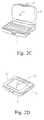
- the display 2may be turned over 180 degrees and mounted on the apparatus body 1 inside out, as will be described with reference to Figs. 2A-2D. Assume that the apparatus is in a closed position with the keyboard of the apparatus body 1 and the screen 17 of the display 2 facing each other, and that the user of the apparatus desires to use a pen input function in place of a keyboard input function. Then, a hook forming part of the latch 15 of the display 2 is released (see Fig. 2A). After the display 2 has been rotated away from the apparatus body 1 to a upright position, the levers 5 are rotated outwardly, and then the display 2 is bodily lifted away from the apparatus body 1. The latch 15 provided on the display 2 is rotated 180 degrees (see Fig. 2B).
- the display 2is turned 180 degrees such that the screen 17 thereof faces outside, i.e., the display 2 is positioned inside out.
- the levers 5are rotated inwardly to connect the display 2 to the apparatus body 1.
- the display 2is lowered to the closed position and then locked to the apparatus body 1 by the hook of the latch 15 (see Fig. 2C).
- the display 2is locked to the apparatus body 1 with the screen 17 thereof facing upward (see FIG. 2D). In this condition, the user can enter data and commands by pressing the screen 17 with a pin 18.
- Figs. 3A and 3Bshow the configurations of the first and second connectors 6 and 7 specifically.
- the connector 6protrudes from the bottom of the support 4 of the display 2 while the connector 1 is positioned in the groove 3 of the apparatus body 1, as stated earlier.
- the connectors 6 and 7each has a symmetric configuration in the right-and-left direction. This allows the display 2 to be connected to the apparatus body with the screen 17 thereof facing inside or outside, as desired.
- Figs. 4A and 4Bare representative of an electrical relation between the connectors 6 and 7. As shown, signal terminals included in the connector 7 and signal terminals included in the connector 6 are exactly symmetrical in respect of the order of arrangement in the right-and-left direction.
- Figs. 5A and 5Bshow respectively the flow of control signals to occur when the display 2 is mounted on the apparatus body 1 with the screen 17 facing inside and the flow to occur when the former is mounted on the latter with the screen 1 7 facing outside.
- the former position and the latter positionbe referred to as a normal position and an inverted position, respectively.
- a control section 11, a position detecting circuit 12 and a selector circuit 9are built in the apparatus body 1.
- the control section 11generates various control signals 14 to be sent to the screen 17 of the display 2.
- the position detecting circuit 12determines if the display 2 is mounted on the apparatus body 1 in the normal position or in the inverted position electrically.
- the selector circuit 9selects particular control signals from the control section 11 in response to a position signal generated by the detecting circuit 12.
- the position detecting circuit 12is implemented by a pull-up resistor 10 by way of example and responsive to the level of a signal line 13 connecting the display 2 and apparatus body 1.
- the detecting circuit 12determines that the display 2 is mounted on the apparatus body 1 in the normal position.
- the detecting circuit 12delivers a high level signal to the selector circuit 9 as a select signal over the signal line 13.
- the selector circuit 9determines that the display 2 is held in the normal position.
- the control signals 14 generated by the control section 11 and meant for the display 2are directly sent to the display 2 via the selector circuit 9 as display data signals 8 (see Fig. 5A).
- the position detecting circuit 12determines that the display 2 is mounted on the apparatus body 1 in the inverted position with the screen 17 facing outside, and delivers a low level signal to the selector circuit 9 via the signal line 13 as a select signal.
- the selector circuit 9inverts the control signals 14 from the control section 11 and then sends them to the display 2 as display data signals 8 (see Fig. 5B).
- the position detecting circuit 12As stated above, whether or not the display 2 is mounted on the apparatus body 1 inside out is automatically determined by the combination of the position detecting circuit 12 and selector circuit 9. This decision is made- when a power switch, not shown, provided on the apparatus body 1 is turned on.
- the selector circuit 9selects control signals 14 matching the position of the display 2 relative to the apparatus body 1 and sends them to the display 2 as display data signals 8.
- numerical data or graphic datafor example, appear on the display 2 in a correct orientation in the up-and-down direction and right-and-left direction.
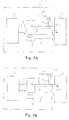
- FIG. 6shows a specific construction of the selector circuit 9.
- the control signals 14 to be sent from the control section 11 to the display 2are represented by DATA1-DATA4, CLK1 and CLK2.
- the select signal to be generated by the position detecting circuit 12 and indicative of the position of the display 2is labeled SELECT.
- the display data signals 8 to be sent from the selector circuit 9 to the display 2are represented by DATA1-DATA4/DATA4-DATA1 and CLK1-CLK2/CLK2-CLK1.
- the position detecting circuit 12produces a high level signal on the signal line 13, turning the signal SELECT meant for the selector 9 to a high level.
- the high level signal SELECTis applied to NAND gates A1-A6, the NAND gates A1-A6 produce NAND of DATA1-DATA4, CLK1 and CLK2 fed thereto from the control section 11.
- the high level signal SELECTis routed through an inverter D1 to NAND gates B1-B6.
- a low level signal SELECTis constantly applied to the NAND gates B1-B6, causing them to output high level signals continuously.
- NAND gates C1-C6receive respectively the high level signals from the NAND gates B1-B6 continuously and, therefore, produce NAND of NAND of DATA1-DATA4, CLK1 and CLK2 fed from the NAND gates A 1-A6.
- the selector 9determines that the display 2 2 is mounted on the apparatus body 1 in the normal position, and sends the control signals 14 (DATA1-DATA4, CLK1 and CLK2) directly to the display 2 as display data signal 8.
- the position detecting circuit 12When the display 2 is mounted on the apparatus body 1 in the inverted position with the screen 17 thereof facing outside, the position detecting circuit 12 produces a low level signal on the signal line 13. This turns the signal SELECT for the selector circuit 9 to a low level.
- the NAND gates A1-A6output high level signals continuously since the signal SELECT remains in a low level.
- the low level signal SELECTis continuously applied to the NAND gates B1-B6 via the inverter D1, causing them to output NAND of DATA4-DATA1, CLK2 and CLK1 fed from the control section 11.
- the NAND gates C1-C6receive respectively the high level signals from the NAND gates A1-A6 continuously and, therefore, produce NAND of NAND of DATA1-DATA4, CLK2 and CLK1 fed from the NAND gates B1-B6.
- the selector circuit 9determines that the display 2 is mounted on the apparatus body 1 inside out, inverts the control signals 14 (DATA1-DATA4, CLK1 and CLK2) fed from the control section 11 in the right-and-left direction, and then sends the inverted control signals 14 to the display 2 as display data signals 8 (DATA4-DATA1, CLK2 and CLK1).
- the latch 15 of the display 2is shown specifically in Figs. 7A, 7B and 7C. As shown, the latch 15 is provided on one edge of the display 2 above the screen 17 and rotatable 180 degrees about a fulcrum 16. When the display 2 is mounted on the apparatus body 1 in the normal position, the hook located at the center of the latch 15 is caused to protrude to the screen 17 side and then fixed in place (see Fig. 7A). When the display 2 is mounted on the apparatus body 1 in the inverted position or inside out, the latch 15 is rotated 180 degrees such that the hook thereof protrudes toward the rear of the screen 17 (see Fig. 7C).
- Figs. 8A and 8Bshow the display 2 mounted on the apparatus body in the normal position and the inverted position, respectively.
- the first connector 6 provided on the bottom of the support 4is connected to the screen, not shown, by a plurality of signal lines, not shown, and receives a power source signal and various control signals from the apparatus body 1.
- the second connector 7 positioned in the groove 3 of the apparatus body 1is connected to other circuitry built in the apparatus 1 by a plurality of signal lines, not shown, and sends the power source signal and control signals to the display 2.
- the support 4mounts the display 2 on the apparatus body such that the former is rotatable relative to the latter about a shaft, not shown, disposed in the support 4. To connect the display 2 to the apparatus body 1, after the support 4 has been aligned with the groove 3, the display 2 is pressed downward to insert the support 4 into the groove 3. As a result, the connectors 6 and 7 are caused to mate each other.
- Figs. 9A and 9Bthere are shown the levers 5 provided at opposite ends of the apparatus body, i.e., at opposite sides of the groove 3 and engageable with opposite ends of the support 4.
- the levers 5are held in a folded or closed position.
- the levers 5are rotated outwardly by the user. Assume that the display 2 should be removed from the apparatus body 1.
- the levers 5are rotated outwardly to release them from opposite ends of the support 4 of the display 2.
- the display 2is bodily lifted while being held together with the support 4 by the user. As the support 4 of the display 2 is pulled out from the groove 3 of the apparatus body 1, the display 2 is fully separated from the body 1.
- the groove 3 of the apparatus body 1is symmetrical in the right-and-left direction. This allows the display 2 to be mounted on the apparatus body 1 in either of the two different positions by being rotated 180 degrees. Further, the levers 5 engaging with opposite ends of the support 4 of the display 2 surely lock the display 2 to the apparatus body 1 without regard to the position of the display 2. Since the levers 5 are rotatably positioned on the apparatus body 1, they can be rotated by the user easily and, therefore, facilitate the mounting and dismounting of the display 2.
- a notebook type information processing apparatus of the present inventionis generally made up of a display and an apparatus body.
- the displayhas a screen on one side thereof for displaying numerical data, graphic data and other data, a support supporting the screen rotatably, a first connector provided on the bottom of the support and connectable to the apparatus body mechanically and electrically, and a latch rotatable 180 degrees for locking the display to the apparatus body in either of a normal position and an inverted position.
- the apparatus bodyhas a groove engageable with the support and located at the rear of a keyboard used to enter data and commands, a second connector positioned in the groove and connectable to the first connector mechanically and electrically, a pair of rotatable levers engageable with opposite ends of the support for locking the display, a control section for generating control signals meant for the screen, a position detecting circuit for determining whether the display is mounted in the normal position or not electrically, and a selector circuit for selectively outputting the control signals from the control section on the basis of the output of the detecting circuit.
- the apparatusallows the user to enter data and commands with a pen easily, reduces the fatigue of the user's arm, and allows the entering operation to be continued for a long time.
Landscapes
- Engineering & Computer Science (AREA)
- Computer Hardware Design (AREA)
- Theoretical Computer Science (AREA)
- Physics & Mathematics (AREA)
- General Physics & Mathematics (AREA)
- Human Computer Interaction (AREA)
- General Engineering & Computer Science (AREA)
- Computer Networks & Wireless Communication (AREA)
- Mathematical Physics (AREA)
- Calculators And Similar Devices (AREA)
Description
- The present invention relates to a light weight andcompact notebook type information processing apparatus and,more particularly, to a notebook type information processingapparatus having an apparatus body and a display separablefrom each other and allowing data and commands to be enteredby a pen.
- An information processing apparatus of the type describedis disclosed in U.S. Patent 4,749,364 by way of example. Theapparatus taught in this prior art has an apparatus bodyconstructed integrally with a keyboard accessible for enteringdata and commands, and an LCD (Liquid Crystal Display) displayphysically separable from the apparatus body. The apparatusbody incorporates a CPU (Central Processing Unit) for executingarithmetic and logical operations in response to data andcommands and outputting the results of such operations. TheLCD display is implemented as a single panel having an LCDscreen on one side thereof for displaying an image, and twofirst plugs. The two first plugs are used to connect the LCD display to the apparatus body and essential with the LCDdisplay.
- The first plugs are each provided with a lever which ispulled when the LCD display is removed from the apparatus bodyor pushed when the former is set on the latter. Further, one ofthe two plugs has a female type electric connector therein. Asignal line is connected to the connector for feeding a powersource signal and control signals to the LCD display. The plugsare each connected to respective socket provided on theapparatus body. One of the sockets associated with the plughaving the female type connector is provided with a male typeconnector which mates with the female type connector whenthe plug is inserted into the socket. The male type connectorreceives the power source signal and control signals sent fromthe apparatus body to the LCD display. The power source signaland control signals are fed to the LCD display via the femaletype connector built in the plug. The sockets are rotatablymounted on the apparatus body. The user of the apparatus canbring down the LCD display affixed to the sockets to a positionwhere the display fully covers the keyboard or to apredetermined angular position.
- A CRT (Cathode Ray Rube) display may be connected to theapparatus body in place of the LCD display. In this case, theCRT display is connected to the apparatus body via a secondplug having a female type connector matching the male type connector of the associated socket, and a cable. When thesecond plug is received in the associated socket, the male andfemale connectors mate with each other to complete electricaland mechanical connection. The power source signal and controlsignals are sent from the apparatus body to the CRT display viathe second plug and cable. The user can remove the CRT displayfrom the apparatus body easily by pulling out the second plugfrom the socket.
- However, the conventional apparatus described above hassome problems left unsolved, as follows. The LCD displayconnected to the apparatus body electrically and mechanicallyis usually positioned such that the screen thereof stands, i.e.,faces obliquely upward, so that the operator can see it easily.Hence, when the operator enters data and commands by pressingthe screen with a pen associated with the apparatus, the LDCdisplay is bodily moved in the same direction as the pen. Thisis undesirable from a manipulation standpoint. In addition,while the operator enters data and commands with a pen on theupright LCD display, the operator's arm is continuously liftedabove the desk or the like. This causes the operator's arm tofatigue noticeably and makes it difficult for the operator toenter data and commands with the pen for a long time.
- Other conventional portable information processing devicesare disclosed in DE-U-9210478, EP-A-0454120, WO 91/05327and a patent abstract of JP-A-02 144 681. This latter documentdescribes a portable type data input device including inversiondetection means which can invert the displayed data verticallyand horizontally so as to be observed by the operatoralways as an erected image.
- It is, therefore, an object of the present invention t oprovide a notebook type information processing apparatus whichenhances easy manipulation, reduces the fatigue of theoperator's arm, and allows the operator to enter data andcommands with a pen for a long time.
- A notebook type information processing apparatus of thepresent invention is generally made up of a display and anapparatus body. The display has a screen on one side thereof fordisplaying numerical data, graphic data and other data, asupport supporting the screen rotatably, a first connectorprovided on the bottom of the support and connectable to theapparatus body mechanically and electrically, and a latchrotatable 180 degrees for locking the display to the apparatusbody in either of a normal position and a position turned over inthe front-and-rear direction. The apparatus body has a grooveengageable with the support and located at the rear of akeyboard used to enter data and commands, a second connectorpositioned in the groove and connectable to the first connectormechanically and electrically, a pair of rotatable leversengageable with opposite ends of the support for locking thedisplay, a control section for generating control signals meantfor the screen, a position detecting circuit for determiningwhether the display is mounted in the normal position or notelectrically, and a selector circuit for selectively outputting the control signals from the control section on the basis of theoutput of the detecting circuit.
- The features and advantages of the present invention willbecome apparent from the following description when taken inconjunction with the accompanying drawings in which:
- Fig. 1 is a perspective view showing a notebook typeinformation processing apparatus embodying the presentinvention;
- Figs. 2A, 2B, 2C and 2D are perspective viewsdemonstrating a procedure for turning a display included in theembodiment 180 degrees and then connecting it to an apparatusbody also included in the embodiment;
- Figs. 3A and 3B are fragmentary views representative of arelation between a first and a second connector provided in thedisplay and the apparatus body, respectively;
- Figs. 4A and 4B are views representative of electricalconnection of the first and second connectors;
- Figs. 5A and 5B are block diagrams schematically showingthe flow of control signals to occur when the display ismounted on the apparatus body in a normal position and the flowto occur when the former is mounted inside out;
- Fig. 6 is a circuit diagram showing a specific constructionof a selector circuit included in the apparatus body;
- Figs. 7A, 7B and 7C are fragmentary perspective viewsshowing a latch for locking the display to the apparatus body;
- Figs. 8A and 8B are fragmentary enlarged sections eachshowing a relation between the apparatus body and the displayin a particular condition; and
- Figs. 9A and 9B are views illustrating the configurationand operation of levers provided on the apparatus body.
- In the figures, the same constituent parts are designatedby the same reference numerals.
- Referring to Fig. 1 of the drawings, a notebook typeinformation processing apparatus embodying the presentinvention is shown. As shown, the apparatus is generally madeup of an
apparatus body 1 and adisplay 2. Thedisplay 2 has ascreen 17 on one side thereof for displaying numerical data,graphic data, etc. Thescreen 17 is rotatably mounted on asupport 4. Afirst connector 6 is provided on the bottom of thesupport 4 and connectable to asecond connector 7, which willbe described, mechanically and electrically. Alatch 15 isprovided on thedisplay 2 and rotatable 180 degrees to lock thedisplay 2 with thescreen 17 facing inside or outside. Theapparatus body 1 is formed with agroove 3 at the rear end of akeyboard which is used to enter data and commands. Thesupport 4 of thedisplay 2 is received in thegroove 3. Thesecond connector 7 is positioned in thegroove 3 andconnectable to thefirst connector 6 mechanically andelectrically. A pair of levers 5 are rotatably mounted on theapparatus body 1 and engaged with opposite ends of thesupport 4 to connect thedisplay 2 to thebody 1. - The
display 2 may be turned over 180 degrees and mountedon theapparatus body 1 inside out, as will be described withreference to Figs. 2A-2D. Assume that the apparatus is in aclosed position with the keyboard of theapparatus body 1 andthescreen 17 of thedisplay 2 facing each other, and that theuser of the apparatus desires to use a pen input function inplace of a keyboard input function. Then, a hook forming part ofthelatch 15 of thedisplay 2 is released (see Fig. 2A). After thedisplay 2 has been rotated away from theapparatus body 1 to aupright position, the levers 5 are rotated outwardly, and thenthedisplay 2 is bodily lifted away from theapparatus body 1.Thelatch 15 provided on thedisplay 2 is rotated 180 degrees(see Fig. 2B). - Subsequently, the
display 2 is turned 180 degrees suchthat thescreen 17 thereof faces outside, i.e., thedisplay 2 ispositioned inside out. After thedisplay 2 in such a position hasbeen inserted into theapparatus body 1, the levers 5 arerotated inwardly to connect thedisplay 2 to theapparatus body 1. Finally, thedisplay 2 is lowered to the closed position andthen locked to theapparatus body 1 by the hook of the latch 15 (see Fig. 2C). As a result, thedisplay 2 is locked to theapparatus body 1 with thescreen 17 thereof facing upward (seeFIG. 2D). In this condition, the user can enter data andcommands by pressing thescreen 17 with apin 18. - Figs. 3A and 3B show the configurations of the first and
second connectors connector 6protrudes from the bottom of thesupport 4 of thedisplay 2while theconnector 1 is positioned in thegroove 3 of theapparatus body 1, as stated earlier. Theconnectors display 2 to be connected to theapparatus body with thescreen 17 thereof facing inside oroutside, as desired. - Figs. 4A and 4B are representative of an electricalrelation between the
connectors connector 7 and signal terminalsincluded in theconnector 6 are exactly symmetrical in respectof the order of arrangement in the right-and-left direction. - Figs. 5A and 5B show respectively the flow of controlsignals to occur when the
display 2 is mounted on theapparatusbody 1 with thescreen 17 facing inside and the flow to occurwhen the former is mounted on the latter with thescreen 1 7facing outside. Let the former position and the latter positionbe referred to as a normal position and an inverted position,respectively. As shown, acontrol section 11, aposition detecting circuit 12 and aselector circuit 9 are built in theapparatus body 1. Thecontrol section 11 generatesvariouscontrol signals 14 to be sent to thescreen 17 of thedisplay 2.Theposition detecting circuit 12 determines if thedisplay 2 ismounted on theapparatus body 1 in the normal position or in theinverted position electrically. Theselector circuit 9 selectsparticular control signals from thecontrol section 11 inresponse to a position signal generated by the detectingcircuit 12. Theposition detecting circuit 12 is implemented by a pull-upresistor 10 by way of example and responsive to the level ofasignal line 13 connecting thedisplay 2 andapparatus body 1.When thesignal line 13 is in a high level, the detectingcircuit 12 determines that thedisplay 2 is mounted on theapparatusbody 1 in the normal position. Then, the detectingcircuit 12delivers a high level signal to theselector circuit 9 as a selectsignal over thesignal line 13. In response, theselector circuit 9 determines that thedisplay 2 is held in the normal position.In this case, the control signals 14 generated by thecontrolsection 11 and meant for thedisplay 2 are directly sent to thedisplay 2 via theselector circuit 9 as display data signals 8(see Fig. 5A). - Assume that the
signal line 13 is in a low level. Then, theposition detecting circuit 12 determines that thedisplay 2 ismounted on theapparatus body 1 in the inverted position withthescreen 17 facing outside, and delivers a low level signal to theselector circuit 9 via thesignal line 13 as a select signal.In response, theselector circuit 9 inverts the control signals14 from thecontrol section 11 and then sends them to thedisplay 2 as display data signals 8 (see Fig. 5B). - As stated above, whether or not the
display 2 is mountedon theapparatus body 1 inside out is automatically determinedby the combination of theposition detecting circuit 12 andselector circuit 9. This decision is made- when a power switch,not shown, provided on theapparatus body 1 is turned on. Theselector circuit 9 selects control signals 14 matching theposition of thedisplay 2 relative to theapparatus body 1 andsends them to thedisplay 2 as display data signals 8. Hence,numerical data or graphic data, for example, appear on thedisplay 2 in a correct orientation in the up-and-down directionand right-and-left direction. - FIG. 6 shows a specific construction of the
selectorcircuit 9. As shown, the control signals 14 to be sent from thecontrol section 11 to thedisplay 2 are represented by DATA1-DATA4,CLK1 and CLK2. The select signal to be generated by theposition detecting circuit 12 and indicative of the position ofthedisplay 2 is labeled SELECT. Further, the display datasignals 8 to be sent from theselector circuit 9 to thedisplay 2are represented by DATA1-DATA4/DATA4-DATA1 and CLK1-CLK2/CLK2-CLK1. - Assume that the
display 2 is mounted on theapparatusbody 1 in the normal position. Then, theposition detectingcircuit 12 produces a high level signal on thesignal line 13,turning the signal SELECT meant for theselector 9 to a highlevel. As the high level signal SELECT is applied to NAND gatesA1-A6, the NAND gates A1-A6 produce NAND of DATA1-DATA4,CLK1 and CLK2 fed thereto from thecontrol section 11. At thesame time, the high level signal SELECT is routed through aninverter D1 to NAND gates B1-B6. Hence, a low level signalSELECT is constantly applied to the NAND gates B1-B6, causingthem to output high level signals continuously. NAND gates C1-C6receive respectively the high level signals from the NANDgates B1-B6 continuously and, therefore, produce NAND of NANDof DATA1-DATA4, CLK1 and CLK2 fed from the NAND gates A 1-A6.As a result, theselector 9 determines that thedisplay 2 2 ismounted on theapparatus body 1 in the normal position, andsends the control signals 14 (DATA1-DATA4, CLK1 and CLK2)directly to thedisplay 2 as display data signal 8. - When the
display 2 is mounted on theapparatus body 1 inthe inverted position with thescreen 17 thereof facing outside,theposition detecting circuit 12 produces a low level signal onthesignal line 13. This turns the signal SELECT for theselector circuit 9 to a low level. In this case, the NAND gatesA1-A6 output high level signals continuously since the signalSELECT remains in a low level. At the same time, the low level signal SELECT is continuously applied to the NAND gates B1-B6via the inverter D1, causing them to output NAND of DATA4-DATA1,CLK2 and CLK1 fed from thecontrol section 11. TheNAND gates C1-C6 receive respectively the high level signalsfrom the NAND gates A1-A6 continuously and, therefore,produce NAND of NAND of DATA1-DATA4, CLK2 and CLK1 fedfrom the NAND gates B1-B6. As a result, theselector circuit 9determines that thedisplay 2 is mounted on theapparatus body 1 inside out, inverts the control signals 14 (DATA1-DATA4,CLK1 and CLK2) fed from thecontrol section 11 in the right-and-leftdirection, and then sends the inverted control signals14 to thedisplay 2 as display data signals 8 (DATA4-DATA1,CLK2 and CLK1). - The
latch 15 of thedisplay 2 is shown specifically in Figs.7A, 7B and 7C. As shown, thelatch 15 is provided on one edgeof thedisplay 2 above thescreen 17 and rotatable 180 degreesabout afulcrum 16. When thedisplay 2 is mounted on theapparatus body 1 in the normal position, the hook located at thecenter of thelatch 15 is caused to protrude to thescreen 17side and then fixed in place (see Fig. 7A). When thedisplay 2 ismounted on theapparatus body 1 in the inverted position orinside out, thelatch 15 is rotated 180 degrees such that thehook thereof protrudes toward the rear of the screen 17 (seeFig. 7C). - Figs. 8A and 8B show the
display 2 mounted on theapparatus body in the normal position and the inverted position,respectively. Thefirst connector 6 provided on the bottom ofthesupport 4 is connected to the screen, not shown, by aplurality of signal lines, not shown, and receives a powersource signal and various control signals from theapparatusbody 1. Thesecond connector 7 positioned in thegroove 3 oftheapparatus body 1 is connected to other circuitry built intheapparatus 1 by a plurality of signal lines, not shown, andsends the power source signal and control signals to thedisplay 2. Thesupport 4 mounts thedisplay 2 on the apparatus bodysuch that the former is rotatable relative to the latter about ashaft, not shown, disposed in thesupport 4. To connect thedisplay 2 to theapparatus body 1, after thesupport 4 has beenaligned with thegroove 3, thedisplay 2 is pressed downward toinsert thesupport 4 into thegroove 3. As a result, theconnectors - Referring to Figs. 9A and 9B, there are shown the levers 5provided at opposite ends of the apparatus body, i.e., at oppositesides of the
groove 3 and engageable with opposite ends of thesupport 4. Usually, the levers 5 are held in a folded or closedposition. To remove thedisplay 2 from theapparatus body 1 orto mount the former on the latter, the levers 5 are rotatedoutwardly by the user. Assume that thedisplay 2 should beremoved from theapparatus body 1. Then, the levers 5 are rotated outwardly to release them from opposite ends of thesupport 4 of thedisplay 2. Subsequently, thedisplay 2 is bodilylifted while being held together with thesupport 4 by the user.As thesupport 4 of thedisplay 2 is pulled out from thegroove 3of theapparatus body 1, thedisplay 2 is fully separated fromthebody 1. - The
groove 3 of theapparatus body 1 is symmetrical inthe right-and-left direction. This allows thedisplay 2 to bemounted on theapparatus body 1 in either of the two differentpositions by being rotated 180 degrees. Further, the levers 5engaging with opposite ends of thesupport 4 of thedisplay 2surely lock thedisplay 2 to theapparatus body 1 without regardto the position of thedisplay 2. Since the levers 5 arerotatably positioned on theapparatus body 1, they can berotated by the user easily and, therefore, facilitate themounting and dismounting of thedisplay 2. - In summary, a notebook type information processingapparatus of the present invention is generally made up of adisplay and an apparatus body. The display has a screen on oneside thereof for displaying numerical data, graphic data andother data, a support supporting the screen rotatably, a firstconnector provided on the bottom of the support andconnectable to the apparatus body mechanically andelectrically, and a latch rotatable 180 degrees for locking thedisplay to the apparatus body in either of a normal position and an inverted position. The apparatus body has a grooveengageable with the support and located at the rear of akeyboard used to enter data and commands, a second connectorpositioned in the groove and connectable to the first connectormechanically and electrically, a pair of rotatable leversengageable with opposite ends of the support for locking thedisplay, a control section for generating control signals meantfor the screen, a position detecting circuit for determiningwhether the display is mounted in the normal position or notelectrically, and a selector circuit for selectively outputtingthe control signals from the control section on the basis of theoutput of the detecting circuit. Hence, the apparatus allows theuser to enter data and commands with a pen easily, reduces thefatigue of the user's arm, and allows the entering operation tobe continued for a long time.
- While the present invention has been described inconjunction with the preferred embodiment thereof, it will nowbe readily possible for those skilled in the art to put thepresent invention into practice in various other manners.
Claims (4)
- A notebook type information processing apparatus having aninput function with a pen, comprising an apparatus body (1) anda display (2),characterized in that said connector means comprises:wherein said display includes a first connector (6) throughwhich control signals are transmitted,and wherein said apparatus body includes:a groove formed on said apparatus body for selectivelylocking and unlocking said display to and from said apparatusbody;connector means (7, 9 and 10), connectable to said firstconnector and through which said control signals are transmittedfrom and to said apparatus body in a configurationally andelectrically symmetrical condition, for connecting said displayto said apparatus bodydetermining means (12) for determining in which of twoorientation states said display is connected to said apparatus body,wherein said display is selectively connected to said apparatusbody in a first and a second orientation state, and said displayis changed back and forth between said first and secondorientation states by disconnecting said display from saidapparatus body, turning said display by 180 degrees around thecenter line of said display, said center line being substantiallyperpendicular to a connecting line between said display and saidapparatus body, and reconnecting said display to said apparatus body;a second connector (7) connectable to said first connectorthrough which said control signals are transmitted from and tosaid apparatus body; andan arranging circuit (9) for arranging spatial orders ofsaid control signals on the basis of said orientation states,said arranging circuit maintaining said spatial orders of saidcontrol signals from and to said second connector when saiddetermining means determines said display is at one of said twoorientation states, and said arranging circuit arranging saidspatial orders of said control signals in the reverse order andsupplying said arranged control signals from and to said secondconnector when said determining means determines said display is inthe other of said two orientation states.
- The notebook type information processing apparatus asclaimed in claim 1, wherein said display (2) comprises a latch (15)rotatable 180 degrees for locking said display (2) to said apparatusbody (1) when said display (2) is closed while selectively facing insideor outside.
- The notebook type information processing apparatus asclaimed in claim 1, wherein said determining means (12) comprises apull-up resistor (10), and wherein a signal line (13) connects said display (2)and said apparatus body (1), said determining means (12) being responsiveto a level of said signal line (13).
- The notebook type information processing apparatus as claimed in claim 1, wherein said processing apparatus includesa support (4) on which said display (2) is rotatably supported, saidfirst connector (6) protruding from this support (4), and wherein saidconnector means is provided in said groove (3) in said apparatusbody (1), said first connector (6) being mechanically and electricallyconnected with said second connector (7) of said connector means insaid groove (3).
Applications Claiming Priority (6)
| Application Number | Priority Date | Filing Date | Title |
|---|---|---|---|
| JP32097792 | 1992-11-30 | ||
| JP32097792 | 1992-11-30 | ||
| JP320977/92 | 1992-11-30 | ||
| JP32410892 | 1992-12-03 | ||
| JP32410892 | 1992-12-03 | ||
| JP324108/92 | 1992-12-03 |
Publications (2)
| Publication Number | Publication Date |
|---|---|
| EP0600410A1 EP0600410A1 (en) | 1994-06-08 |
| EP0600410B1true EP0600410B1 (en) | 2001-06-13 |
Family
ID=26570305
Family Applications (1)
| Application Number | Title | Priority Date | Filing Date |
|---|---|---|---|
| EP93119205AExpired - LifetimeEP0600410B1 (en) | 1992-11-30 | 1993-11-29 | A notebook type information processing apparatus having input function with pen |
Country Status (5)
| Country | Link |
|---|---|
| US (1) | US5600580A (en) |
| EP (1) | EP0600410B1 (en) |
| AU (1) | AU668432B2 (en) |
| CA (1) | CA2110189C (en) |
| DE (1) | DE69330334T2 (en) |
Cited By (4)
| Publication number | Priority date | Publication date | Assignee | Title |
|---|---|---|---|---|
| DE102005008201B4 (en)* | 2004-08-27 | 2007-05-10 | Fujitsu Ltd., Kawasaki | Electronic device and attachment unit |
| US8102457B1 (en) | 1997-07-09 | 2012-01-24 | Flashpoint Technology, Inc. | Method and apparatus for correcting aspect ratio in a camera graphical user interface |
| US8127232B2 (en) | 1998-12-31 | 2012-02-28 | Flashpoint Technology, Inc. | Method and apparatus for editing heterogeneous media objects in a digital imaging device |
| US9224145B1 (en) | 2006-08-30 | 2015-12-29 | Qurio Holdings, Inc. | Venue based digital rights using capture device with digital watermarking capability |
Families Citing this family (38)
| Publication number | Priority date | Publication date | Assignee | Title |
|---|---|---|---|---|
| KR0178893B1 (en)* | 1995-10-04 | 1999-05-15 | 김광호 | Hinged device combined with LCD screen of notebook computer |
| JP3222764B2 (en)* | 1996-05-17 | 2001-10-29 | シャープ株式会社 | Information processing device |
| US5805415A (en)* | 1996-10-03 | 1998-09-08 | Hewlett-Packard Company | Detachable flat panel computer display and support |
| DE19700875A1 (en)* | 1997-01-04 | 1998-07-09 | Roland Dr Ing Timmel | Portable data processing equipment |
| US5831817A (en)* | 1997-06-16 | 1998-11-03 | Mitac International Corporation | Computer apparatus having a movable liquid crystal display |
| US6205021B1 (en)* | 1998-02-26 | 2001-03-20 | Micron Electronics, Inc. | Method for operating an input device and a laptop computer |
| US6163326A (en)* | 1998-02-26 | 2000-12-19 | Micron Electronics, Inc. | Input device for a laptop computer |
| US6125040A (en)* | 1998-02-27 | 2000-09-26 | Fujitsu Limited | Information processing apparatus and hook mechanism applicable to the apparatus |
| JP4212708B2 (en)* | 1998-03-16 | 2009-01-21 | 富士通株式会社 | Information processing apparatus and electronic device |
| DE19835432C2 (en)* | 1998-08-05 | 2002-01-31 | Fujitsu Siemens Computers Gmbh | Portable computer system with a screen suitable for combined use |
| US6343006B1 (en) | 1998-11-20 | 2002-01-29 | Jerry Moscovitch | Computer display screen system and adjustable screen mount, and swinging screens therefor |
| WO2000039493A1 (en) | 1998-12-23 | 2000-07-06 | Jerry Moscovitch | Computer display screen system and adjustable screen mount, and swinging screens therefor |
| US6702604B1 (en)* | 1999-08-23 | 2004-03-09 | Jerry Moscovitch | Universal quick connector apparatus for an LCD monitor |
| JP2003507768A (en) | 1999-08-23 | 2003-02-25 | マス エンジニアード デザイン | Universal immediate connection device for LCD monitor |
| JP3584010B2 (en) | 2000-06-08 | 2004-11-04 | 株式会社ソニー・コンピュータエンタテインメント | Entertainment device and monitor device used therefor |
| GB2367389A (en)* | 2000-09-30 | 2002-04-03 | Graham John Marklew | An electronic notebook and textbook with removable hinges |
| US7046233B2 (en)* | 2001-03-27 | 2006-05-16 | Sony Corporation | Electronic apparatus |
| DE10126474C2 (en)* | 2001-05-31 | 2003-07-31 | Adrian Thome | Portable data processing equipment |
| US6963487B2 (en)* | 2001-10-25 | 2005-11-08 | Hewlett-Packard Development Company, L.P. | Pedestal computer docking station |
| KR100460956B1 (en)* | 2002-07-03 | 2004-12-09 | 삼성전자주식회사 | A Keyboard of a personal digital assistant |
| WO2004017026A1 (en)* | 2002-08-13 | 2004-02-26 | Vega Grieshaber Kg | Input and output device for detachable connection to an electronic device |
| TW594126B (en)* | 2002-10-03 | 2004-06-21 | Wistron Corp | Liquid crystal display panel and notebook computer having the same |
| TWI248017B (en)* | 2003-03-27 | 2006-01-21 | Benq Corp | A display for electronic devices |
| KR100745813B1 (en)* | 2003-08-11 | 2007-08-02 | 엘지전자 주식회사 | Bidirectional latch assembly and electronic device using same |
| KR100585105B1 (en)* | 2003-11-05 | 2006-06-01 | 삼성전자주식회사 | A timing controller capable of reducing memory update operation current, an LCD driver having the same, and a display data output method |
| EP1530118A1 (en)* | 2003-11-06 | 2005-05-11 | Dicom AG | Expansion device for a flat screen and flat screen |
| US20050202879A1 (en)* | 2004-03-09 | 2005-09-15 | Intec, Inc. | Detachable display for video console |
| JP4603317B2 (en)* | 2004-08-27 | 2010-12-22 | 富士通株式会社 | Electronic device and circuit board |
| US7673838B2 (en)* | 2005-02-16 | 2010-03-09 | Innovative Office Products, Inc. | Quick release assembly for an electronic device |
| GB0609240D0 (en) | 2006-05-10 | 2006-06-21 | Mitchell Ciaran | Seat top console for vehicle entertainment and accessories |
| GB2448958B (en)* | 2006-05-10 | 2009-06-17 | Audiovox Incaar Systems Gmbh | Entertainment apparatus |
| TWI324291B (en)* | 2006-07-26 | 2010-05-01 | Compal Electronics Inc | Connection assembly for connecting bodies, and portable electronic apparatus and base using the same |
| US20080316695A1 (en)* | 2007-06-07 | 2008-12-25 | Xplore Technologies Corporation Of America | Electronic Enclosure Fastening Belt |
| TWI454967B (en)* | 2008-07-16 | 2014-10-01 | Htc Corp | Electronic device and keyboard module thereof |
| US20110155873A1 (en)* | 2009-12-30 | 2011-06-30 | Winegard Company | Mounting system for releasably securing an entertainment module to an automotive headrest |
| TW201447537A (en)* | 2013-06-05 | 2014-12-16 | Hon Hai Prec Ind Co Ltd | Electronic device |
| WO2015047245A1 (en)* | 2013-09-25 | 2015-04-02 | Hewlett-Packard Development Company, L.P. | Locking bar for a computer |
| CN105508837B (en)* | 2015-12-31 | 2018-01-19 | 深圳科润视讯技术有限公司 | Interactive intelligent all-in-one and its operating method |
Family Cites Families (11)
| Publication number | Priority date | Publication date | Assignee | Title |
|---|---|---|---|---|
| AU594385B2 (en)* | 1986-03-20 | 1990-03-08 | Wang Laboratories, Inc. | Display attachment apparatus |
| JPS6339731A (en)* | 1986-08-05 | 1988-02-20 | Mitsubishi Electric Corp | Wire electric spark machining device |
| JPH02144681A (en)* | 1988-11-26 | 1990-06-04 | Nitto Kohki Co Ltd | portable data entry device |
| US5240427A (en)* | 1989-06-23 | 1993-08-31 | Kabushiki Kaisha Toshiba | Portable apparatus having cable electrically connecting display unit and base unit |
| US5049862A (en)* | 1989-10-06 | 1991-09-17 | Communication Intelligence Corporation ("Cic") | Keyless flat panel portable computer--computer aided notebook |
| JPH03144818A (en)* | 1989-10-31 | 1991-06-20 | Toshiba Corp | Portable electronic equipment |
| US5268817A (en)* | 1990-04-27 | 1993-12-07 | Kabushiki Kaisha Toshiba | Portable computer with keyboard and having display with coordinate input tablet rotatably mounted to face either toward or away from keyboard when closed over keyboard |
| EP0454120A3 (en)* | 1990-04-27 | 1992-12-30 | Kabushiki Kaisha Toshiba | Portable computer comprising keyboard and coordinate input tablet |
| US5333116A (en)* | 1990-05-04 | 1994-07-26 | Ast Research, Inc. | Combination laptop and pad computer |
| US5241303A (en)* | 1991-12-26 | 1993-08-31 | Dell Usa, L.P. | Portable computer with physical reconfiguration of display connection for stylus and keyboard entry |
| DE9210478U1 (en)* | 1992-08-05 | 1992-10-01 | Ma, Hsi Kuang, Taipeh/T'ai-pei | computer |
- 1993
- 1993-11-29CACA002110189Apatent/CA2110189C/ennot_activeExpired - Lifetime
- 1993-11-29DEDE69330334Tpatent/DE69330334T2/ennot_activeExpired - Lifetime
- 1993-11-29EPEP93119205Apatent/EP0600410B1/ennot_activeExpired - Lifetime
- 1993-11-30AUAU52059/93Apatent/AU668432B2/ennot_activeExpired
- 1995
- 1995-06-06USUS08/468,334patent/US5600580A/ennot_activeExpired - Lifetime
Cited By (6)
| Publication number | Priority date | Publication date | Assignee | Title |
|---|---|---|---|---|
| US8102457B1 (en) | 1997-07-09 | 2012-01-24 | Flashpoint Technology, Inc. | Method and apparatus for correcting aspect ratio in a camera graphical user interface |
| US8970761B2 (en) | 1997-07-09 | 2015-03-03 | Flashpoint Technology, Inc. | Method and apparatus for correcting aspect ratio in a camera graphical user interface |
| US8127232B2 (en) | 1998-12-31 | 2012-02-28 | Flashpoint Technology, Inc. | Method and apparatus for editing heterogeneous media objects in a digital imaging device |
| US8972867B1 (en) | 1998-12-31 | 2015-03-03 | Flashpoint Technology, Inc. | Method and apparatus for editing heterogeneous media objects in a digital imaging device |
| DE102005008201B4 (en)* | 2004-08-27 | 2007-05-10 | Fujitsu Ltd., Kawasaki | Electronic device and attachment unit |
| US9224145B1 (en) | 2006-08-30 | 2015-12-29 | Qurio Holdings, Inc. | Venue based digital rights using capture device with digital watermarking capability |
Also Published As
| Publication number | Publication date |
|---|---|
| EP0600410A1 (en) | 1994-06-08 |
| AU5205993A (en) | 1994-06-09 |
| CA2110189C (en) | 1999-06-15 |
| AU668432B2 (en) | 1996-05-02 |
| DE69330334T2 (en) | 2002-05-29 |
| DE69330334D1 (en) | 2001-07-19 |
| CA2110189A1 (en) | 1994-05-31 |
| US5600580A (en) | 1997-02-04 |
Similar Documents
| Publication | Publication Date | Title |
|---|---|---|
| EP0600410B1 (en) | A notebook type information processing apparatus having input function with pen | |
| JP3571635B2 (en) | Apparatus having multiple display devices and display method thereof | |
| US5526493A (en) | Docking detection and suspend circuit for portable computer/expansion chassis docking system | |
| US5745340A (en) | Separable display of computer generated information | |
| US4749364A (en) | Display attachment apparatus | |
| US7221562B2 (en) | Portable computer | |
| US5193069A (en) | Portable computer to which different types of flat display panels can be attached | |
| US6208508B1 (en) | Space-saving docking station for vertically supporting an opened notebook computer | |
| US8127066B2 (en) | Computer system with peripheral modules attached to a display/CPU assembly | |
| US5969696A (en) | Standard interface system between different LCD panels and a common frame buffer output | |
| JPH0159592B2 (en) | ||
| KR100378996B1 (en) | portable computer mounted separable monitor or multifuntional augmented separable multi-monitor | |
| US20040263423A1 (en) | Video signal converter for a detachable display module of a portable computer | |
| JPH06222857A (en) | Note book type information processor having pen input function | |
| JPH10171382A (en) | Display device and electronic equipment | |
| KR100584685B1 (en) | Monitor folding all-in-one computer | |
| CN207199238U (en) | Display device | |
| EP0395033A2 (en) | Portable computer to which different types of flat display panels can be attached | |
| JP3145587B2 (en) | Image forming device | |
| KR100294261B1 (en) | Portable computer | |
| JPH11149327A (en) | Portable information electronic equipment | |
| JP3190695B2 (en) | Interface adapters and portable electronic devices | |
| JP2559451Y2 (en) | Notebook computer system | |
| JPH0519700A (en) | Picture display device | |
| JPH09294221A (en) | Electronic equipment provided with image pickup device |
Legal Events
| Date | Code | Title | Description |
|---|---|---|---|
| PUAI | Public reference made under article 153(3) epc to a published international application that has entered the european phase | Free format text:ORIGINAL CODE: 0009012 | |
| 17P | Request for examination filed | Effective date:19940411 | |
| AK | Designated contracting states | Kind code of ref document:A1 Designated state(s):DE FR GB | |
| 17Q | First examination report despatched | Effective date:19980202 | |
| GRAG | Despatch of communication of intention to grant | Free format text:ORIGINAL CODE: EPIDOS AGRA | |
| GRAG | Despatch of communication of intention to grant | Free format text:ORIGINAL CODE: EPIDOS AGRA | |
| GRAG | Despatch of communication of intention to grant | Free format text:ORIGINAL CODE: EPIDOS AGRA | |
| GRAH | Despatch of communication of intention to grant a patent | Free format text:ORIGINAL CODE: EPIDOS IGRA | |
| GRAH | Despatch of communication of intention to grant a patent | Free format text:ORIGINAL CODE: EPIDOS IGRA | |
| GRAA | (expected) grant | Free format text:ORIGINAL CODE: 0009210 | |
| AK | Designated contracting states | Kind code of ref document:B1 Designated state(s):DE FR GB | |
| REF | Corresponds to: | Ref document number:69330334 Country of ref document:DE Date of ref document:20010719 | |
| ET | Fr: translation filed | ||
| REG | Reference to a national code | Ref country code:GB Ref legal event code:IF02 | |
| PLBE | No opposition filed within time limit | Free format text:ORIGINAL CODE: 0009261 | |
| STAA | Information on the status of an ep patent application or granted ep patent | Free format text:STATUS: NO OPPOSITION FILED WITHIN TIME LIMIT | |
| 26N | No opposition filed | ||
| REG | Reference to a national code | Ref country code:FR Ref legal event code:TP Owner name:NEC PERSONAL COMPUTERS, LTD, JP Effective date:20111024 | |
| REG | Reference to a national code | Ref country code:GB Ref legal event code:732E Free format text:REGISTERED BETWEEN 20120223 AND 20120229 | |
| PGFP | Annual fee paid to national office [announced via postgrant information from national office to epo] | Ref country code:FR Payment date:20121130 Year of fee payment:20 Ref country code:DE Payment date:20121128 Year of fee payment:20 | |
| PGFP | Annual fee paid to national office [announced via postgrant information from national office to epo] | Ref country code:GB Payment date:20121126 Year of fee payment:20 | |
| REG | Reference to a national code | Ref country code:DE Ref legal event code:R071 Ref document number:69330334 Country of ref document:DE | |
| REG | Reference to a national code | Ref country code:GB Ref legal event code:PE20 Expiry date:20131128 | |
| PG25 | Lapsed in a contracting state [announced via postgrant information from national office to epo] | Ref country code:GB Free format text:LAPSE BECAUSE OF EXPIRATION OF PROTECTION Effective date:20131128 Ref country code:DE Free format text:LAPSE BECAUSE OF EXPIRATION OF PROTECTION Effective date:20131130 |