EP0600298A1 - Working method for operating and means for determination and evaluation of the conditions of the vascular systems - Google Patents
Working method for operating and means for determination and evaluation of the conditions of the vascular systemsDownload PDFInfo
- Publication number
- EP0600298A1 EP0600298A1EP93118494AEP93118494AEP0600298A1EP 0600298 A1EP0600298 A1EP 0600298A1EP 93118494 AEP93118494 AEP 93118494AEP 93118494 AEP93118494 AEP 93118494AEP 0600298 A1EP0600298 A1EP 0600298A1
- Authority
- EP
- European Patent Office
- Prior art keywords
- time
- function
- values
- determined
- blood
- Prior art date
- Legal status (The legal status is an assumption and is not a legal conclusion. Google has not performed a legal analysis and makes no representation as to the accuracy of the status listed.)
- Withdrawn
Links
Images


Classifications
- A—HUMAN NECESSITIES
- A61—MEDICAL OR VETERINARY SCIENCE; HYGIENE
- A61B—DIAGNOSIS; SURGERY; IDENTIFICATION
- A61B5/00—Measuring for diagnostic purposes; Identification of persons
- A61B5/02—Detecting, measuring or recording for evaluating the cardiovascular system, e.g. pulse, heart rate, blood pressure or blood flow
- A61B5/02007—Evaluating blood vessel condition, e.g. elasticity, compliance
- A—HUMAN NECESSITIES
- A61—MEDICAL OR VETERINARY SCIENCE; HYGIENE
- A61B—DIAGNOSIS; SURGERY; IDENTIFICATION
- A61B5/00—Measuring for diagnostic purposes; Identification of persons
- A61B5/02—Detecting, measuring or recording for evaluating the cardiovascular system, e.g. pulse, heart rate, blood pressure or blood flow
- A61B5/024—Measuring pulse rate or heart rate
- A61B5/02416—Measuring pulse rate or heart rate using photoplethysmograph signals, e.g. generated by infrared radiation
- A—HUMAN NECESSITIES
- A61—MEDICAL OR VETERINARY SCIENCE; HYGIENE
- A61B—DIAGNOSIS; SURGERY; IDENTIFICATION
- A61B8/00—Diagnosis using ultrasonic, sonic or infrasonic waves
- A61B8/06—Measuring blood flow
Definitions
- the inventionrelates to a working method for operating and to a device for determining and evaluating the state of vascular systems according to the preamble of claims 1 and 33, respectively.
- a device for recording and analyzing the blood supply to human skinhas become known, for example, from German patent DE 33 18 746 C2.
- the facilityuses the principle of light reflection rheography (LRR).
- LRRlight reflection rheography
- a measuring deviceis used, which is equipped with a light measuring head to be attached to a skin area to be examined with double-adhesive foil rings, the measuring head having openings in which an optical radiation receiver and a plurality of radiation sources are arranged, and the radiation receiver and the radiation sources directly lie on the surface of the skin.
- the radiation sourceemits radiation with a wavelength in the near IR range of the spectrum.
- An electronic evaluation circuitselectively detects and records the time profile of the reflected or backscattered radiation component, while at the same time suppressing the volume pulsations.
- the above-mentioned measuring deviceis disclosed in European Patent 0 063 649 B1.
- the arithmetic circuitshould then calculate physical evaluation parameters for the analog LRR curves.
- the output signalis frequency-analyzed by means of the arithmetic circuit and, in addition to determining the amplitude profile of the circulatory rhythm, the frequency composition thereof is also determined.
- a Fourier transformation of the output signal of the measuring devicetakes place in selected frequency ranges. The filling time of the blood vessels t0, the fall time t a from a measured value 90% to a measured value 10%, and the half-life t h , ie the time in which a drop from 100% to 50% occurs, are determined as evaluation parameters.
- the computer analysis of the LRR curvesis summarized in four points in the known solution.
- the results of the calculation of the venous filling phaseare output first.
- the fall time t awhich is free from the fault-prone boundary conditions, the half-life already mentioned and other parameters are calculated.
- the pressure differenceis calculated by filling the vessels and under load.
- the area under the LRR curve or the steepness of the filling phase for diagnosis of the state of the venous hemodynamicsare also used as evaluation parameters.
- the object of the inventionis therefore to provide a working method for operating and a device for determining and evaluating the state of macro and micro vessel systems on the basis of a qualitatively new photoplethysmography, the clinical information content of the detected bio-signals being significantly increased and a comprehensive relevant assignment of statistically verified changes in characteristics to corresponding pathophysical and clinical conditions are possible.
- the inventionis based on the basic idea that it is possible to determine the dynamic behavior of a linear system in that the system to be examined has a defined input function x e (t), which can be, for example, a step or delta function , is applied.
- x e (t)a defined input function
- x a (t)a typical jump or shock transition function is obtained at the system output.
- This functioncharacterizes the dynamic system behavior.
- dimensionless or standardized variablesare expediently sought.
- the dynamic behavior of the step response or output variable x a (t)can be described by characteristic values which can be derived from the function curve of x a (t).
- the settling time t Eis typical, for example.
- a step functionis triggered by sudden, one-time action, for example the sudden lifting of a hand or a leg, an acoustic signal or in the form of a pressure mechanical load.
- the output size of the systemi. H. of the peripheral area to be examined, for example a big toe, then adjusts itself according to the respective concrete condition.
- microcirculation in the sense of chaos theoryhas a basic order, i. H. a working point. There is also determined chaos. In order to determine the operating point, the microcirculation is determined in the stationary state of the system to be examined over a certain measuring time.
- analysis of the spread of the heart ratecan be used to determine whether there is a non-normal condition. It It was recognized that the smaller the spread of the heart rate, the greater the risk or the potential probability of an illness.
- the procedure described abovecan then be used to determine, for example, the effects of pharmaceuticals or drugs directly and without subjective influence from the subject or a third party.
- the working method for operating a device for determining and evaluating the state of vascular systemscan be used in regular flight fitness examinations or similar fitness examinations.
- periodic or continuous on-board monitoringsuch.
- the onset of cardiac deathis characterized by the transition from an irregular pattern of cardiac activity to a simple pattern. From the analysis of the microcirculation in a peripheral area (tissue region) it is therefore possible, by simply monitoring the continuity or discontinuity of the cardiac activity or the heart rate, to determine a heart disease or to recognize imminent cardiac arrest in good time.
- the method according to the inventionbased on the evaluation of micro and macro circulation processes in blood vessels, is based on the above-described knowledge of the stochastic function x tot (t) in the time domain.
- the measure x I (t) for the waves of the 1st order already mentionedcontains the "carrier frequency" of the microcirculation function, the heart rate (cardiac period T I ). At such an operating point T I is modulated, the scatter S T occurring.
- a simpler cardiac rhythm patternmeans that the scatter S T decreases more and more and the working point is outside the optimal range.
- the working point and the scatterare therefore to determine the so-called normal case depending on the respective age as well as the possible optimum and to save it for further evaluation as comparison values or in the form of a normal characteristic curve.
- the function X I (t) from x tot (t)can be hidden, separated and represented by a bandpass filter with a cut-off frequency of 0.6 Hz ⁇ f ⁇ 9 Hz.
- the measure for the higher order wavescan be summarized with x bio (t). These higher-order waves, which are long-wave, can also be filtered out of x ges (t) by a low-pass filter or bandpass filter with an upper cut-off frequency f g of approximately 0.5 ... 0.6 Hz.
- error-detecting and error-correcting codesare used according to the invention.
- additional redundancyis built into the respective code.
- a method of correcting errorsconsists in realizing this redundancy by repeating the respective evaluations and comparing their results. If there is a match, there is no error; if there is a mismatch, a repeated repetition is carried out, it being very likely that the two matching code words (characteristic values) are recognized as the correct code word, and error correction can thus be made possible.
- the complex system of the blood circulation in the sense of a Modelcan be traced back to the basic circuit of electrical engineering and thus the interaction of the heart with the entire blood circulation system including periphery can be modeled by a voltage source E, an associated internal resistance R i and a consumer (load resistance) R a .
- T Brepresents the systolic peak time in the blood pressure curve
- T Athe fall time between the systolic peak and the dicrotic notch (incisor).
- RPW2 ⁇applies analogously to RPW1 ⁇
- the relationshipwas recognized as the target value for the cardiac period T H that T H SHOULD [ms] ⁇ 508 [1 + 1 / RPW1 ⁇ ] ⁇ 508 [1 + P D / P S ] is taking the difference [T H ACTUAL - T H TARGET ] taking into account the modulation limits for P S and P D for a therapy to be initiated (change in cardiac output as a product of stroke volume and heart rate).
- the method for evaluating micro and macro circulation processes in blood vesselsis based on a representation of the generalized average function derived from x tot (t): the autocorrelation function ⁇ xges ( ⁇ ).
- a so-called microcirculation gradient M micro and a cross-correlation function ⁇ xy ( ⁇ ) for two microcirculation signalsare introduced.
- an autocorrelation function(for the subfunctions x I (t), x II (t), x III (t)) is formed on the assumption that the N-th order waves are statistically independent of one another.
- ⁇ xges ( ⁇ )⁇ xI ( ⁇ ) + ⁇ xII ( ⁇ ) + ⁇ xIII ( ⁇ ), where ges xges ( ⁇ ) represents the autocorrelation function of the integral total volume pulsation .
- the mean period of ⁇ xI ( ⁇ )is in the range 0.7 ... 1.3 s, that of ⁇ xII ( ⁇ ) is in the interval 3 ...
- ⁇ xIII ( ⁇ )is in the range from approx. 10 ... 15 s.
- ⁇ xges ( ⁇ )⁇ xI ( ⁇ ) + ⁇ xbio ( ⁇ ) with ⁇ xbio ( ⁇ ) as an autocorrelation function of the bio-periodic.
- the envelope of ⁇ xges ( ⁇ )is now considered in a simple manner, which, in the presence of x II (t) and x III (t), does not form a horizontal line except in the maxima and minima, but has a corresponding tangential inclination. If a horizontal occurs as a tangent, the proportion of x bio (t) according to the invention is zero on average.
- Mikrozirkulationsgradientthe micro M, which is derived from the autocorrelation function ⁇ x tot ( ⁇ ), defined and used for evaluation.
- the average blood flow velocity between two measuring pointscan be derived in a simple manner from the determination of the temporal position ⁇ opt of the maximum of ⁇ x1x2 ( ⁇ ).
- defined input functionsare created according to the invention for determining and assessing the dynamic behavior of the vessel area to be examined. This can be done, for example, by a sudden or sudden change in the pressing force of a sensor for detecting the reflected light in the area under investigation.
- the response function or jump transition function recorded with the sensoris now an expression of the dynamic behavior of the microcirculation area penetrated by the radiation, ie the integral volume pulsation of the microcirculation.
- a positive or a negative hydrostatic jumpis conceivable as an input function.
- the step response obtainedcan now be used for evaluation in a simple manner, for example by the size of the settling time t E a classification is carried out. This means that time-discrete photoplethsymography is also used as a basis for this dynamic system diagnosis.
- By triggering a negative and positive hydrostatic pressure jumpthe otherwise required, complicated exercise program for test subjects or patients is eliminated.
- the emptying and therefrom a "settling" or "emptying time” t EL of the micro and connected macrovascular systemis measured and as a result of the positive hydrostatic pressure jump the refilling with the "settling" or "filling time t EF is determined. It was recognized that normally the connection between emptying and filling applies t EF ⁇ 1.6 t EL , in the case of venous valve insufficiency, however, the settling times are the same.
- the vasomotor systemcan be determined with a further embodiment of the invention.
- the quality of the vasomotoris z. B. judged by triggering an acoustic stimulus (shock) as an input variable.
- the response x a (t) obtainedarises as a shock transfer function.
- the settling time t Eis understood to be the time after which the response to the input shock function remains within the range of ⁇ 5% of x a ( ⁇ ).
- vasomotor gradient M vaso 1was introduced according to the invention .
- the vasomotor gradient M vaso 2can be introduced as another possible parameter from the amplitude relationships .
- the amplitudes of the photoplethysmographically determined signalhave the disadvantage that they are pressure-dependent, are determined in part by multiple factors which can hardly be influenced from the outside and are hardly verifiable. With the equivalent evaluation of time parameters, a similar leap in quality as in communications technology is achieved in the transition from amplitudes to frequency modulation. In order to be able to generalize the results, it is also based on relative (related or standardized) quantities.
- T D / T I0.5
- B / A0.618.
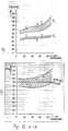
- FIGS. 3a to 3cillustrate the normal values of standardized parameters T D / T I , T G / T I , S TI / T I and the conditions in the optimal case OPT, depending on the age. It should be noted that the representations are normalized values.
- the ratio T D / T Idenotes the normalized dicrotic time, the ratio T G / T I the normalized peak time and the ratio S TI / T I the normalized spread of the pulse period.
- the classification of normal valuescan be clearly seen.
- the solid lineseach represent the mean value curve without consideration of the scatter range for healthy people.
- the dash-dotted line in FIGS. 3a and 3brepresent the theoretical optimum OPT.
- the proposed measurement of the standardized time relationships and the determination of the scattering, taking into account the standardized amplitude values,can eliminate measurement errors that otherwise occur and thus simplify the evaluation.
- the blood circulationcan be represented as a model in which an analogy to the basic electrical circuit in the sense of the interaction between the voltage source (heart) and the periphery R a (resistance vessels of the microcirculation functional unit, 25 shows) is considered via the bloodstream.
- the relative peripheral resistance RPW 1can be determined as an expression of the internal resistance R i acting in the basic circuit.
- Fig. 7the dependence between systolic and diastolic blood pressure P S , P D with different values of the relative peripheral resistance RPW1 is shown as a parameter, the normal blood pressure values including the fixed modulation limits. It is clear that the resistance RPW 1 introduced is a quantitative measure of the interaction with the periphery.
- FIG. 8shows a flow velocity in an arm artery recorded with an ultrasound Doppler, from which the characteristic time parameters T A , T B according to FIG. 6 can also be derived.
- FIG. 9shows the dependency of the relative peripheral resistance RPW2 defined in accordance with the invention, which corresponds to the load resistance R a in the basic circuit and can be determined for each volume pulse of the microcirculation that occurs, as a function of age.
- the dicrotic times T D based on this resistance and the basic arterial vibration T AGare also listed.
- Fig. 9ashows the relationships in female, Fig. 9b in male subjects.
- the classification of the determined optimal resistance RPW2 opt1.618 is clearly shown.
- FIG. 11shows the optimal interaction between heart and periphery in the sense of FIG. 5.
- P a *represents the normalized consumer power (consumer power P a is related to the power output P k of the generator in the event of a short circuit).
- FIG. 12as a further exemplary embodiment of the invention, normal ranges as a function of age for the resting blood pressure (FIG. 12a) are derived therefrom for the relative peripheral resistance RPW1 ⁇ (Fig. 12b), for RPW2 ⁇ (Fig. 12c) and for the relative mean (blood) current flow I real (Fig. 12d).
- Examples A, B, Care the measured values for test subjects shown in Fig. 10. This shows that only subject C is in the normal range.
- the autocorrelation functionsare formed for evaluating the information obtained from the microcirculation.
- the proportions of the partial autocorrelation functionsdepend on the proportions of the associated time functions x I (t), x II (t), x III (t) within x tot (t).
- the total autocorrelation functionpresents itself as a superposition of the partial autocorrelation functions.
- the mean periods of ⁇ xI ( ⁇ )are approximately 0.75 s, those of ⁇ xIII ( ⁇ ) approximately 14 s; in Fig. 13b the respiratory component for about 5 s.
- M microThe envelope of ⁇ xges ( ⁇ ) must normally fall and rise again in a certain time interval, as shown in FIGS. 13a and 13b.
- a cross-correlation function ⁇ xy ( ⁇ )can be determined as a measure of the statistical dependency of two functions x (t) and y (t).
- FIG. 14illustrates how on the basis of the cross correlation function CCF, the mean blood flow velocity v can be determined Ström between two measuring points.
- the receivers E1 and E2 showndeliver the signals x 1 (t) and x 2 (t) emitted by the transmitter S and reflected in the peripheral area.
- the input variable at measuring point E1can be abruptly changed by a single, short cough, whereby a quasi needle pulse is generated which propagates from measuring point E1 to measuring point E2.
- t Eis the time after which the response x a (t) to an input-side jump remains within the bounds of ⁇ 5% of x a ( ⁇ ).
- t Eis the time after which the response x a (t) to an input-side jump remains within the bounds of ⁇ 5% of x a ( ⁇ ).
- the measurement of the specific settling time t E of the examined peripheral areaallows an assessment of the subject's vasomotor system. This is based on the fact that the vasomotor system cannot be separated from the microcirculation and is part of the pulsating system. In other words, the quality of the vasomotor system can be assessed by triggering an acoustic stimulus (impact function).
- the answer x a (t) to thisis an easy-to-evaluate shock transfer function.
- the time between the triggering of the stimulus and the beginning of the transitionis referred to as t0 (running time).
- FIG. 17ashows vasomotor reactions in a test person measured on the finger and FIG. 17b shows the reactions measured simultaneously on the big toe.
- M vaso 11 - t A / n ⁇ t A respectively.
- M vaso 11 - 1 / n.
- the number of enveloping volume pulsesis therefore a measure of the quality of the vasomotor system. The more volume pulses are detected by the vasomotor reaction, the closer M vaso 1 approaches the value 1.
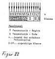
- vasolinealBy assigning the number n of the volume pulses detected to a class, a type of vasolineal can be constructed, as shown in FIG. 22. 22, this ruler is based on an average cardiac cycle duration of approximately 850 ms. It is applied to the vasomotor curve and the number n and the class are read. On the basis of this, a classification in M vaso 1 of very good, good, little reaction, no reaction.
- vasomotor gradient M vaso 2can be determined as an additional parameter.
- a classificationcan be carried out in the area defined above.
- the following procedureproves to be significantly more advantageous. Because of the connected vessels in the peripheral area to be examined, there is a direct connection when the pressure changes between the macro and micro vessels.
- the following system testis carried out to determine and assess the dynamic behavior of the peripheral vascular region to be examined. At room temperature of approx. 22 to 24 ° C, a sensor head (e.g. by means of a clamp) is placed in the starting position in the patient's back position on the tissue region to be examined, e.g. B. positioned on the big toe. In this position, the subject has approximately a hydrostatic pressure of 0.
- the vascular systemempties due to a negative, hydrostatic jump, the suction effect creates a permanent reaction back into the capillary and arterial area.
- a settling or emptying time t EL of the micro and macrovascular systemis thus obtained, which is achieved where the emptying process has assumed a constant value. Consequently, the emptying time t EL is a direct measure of the dynamic behavior of the examined venous system, for example a leg.
- the jump duration ⁇ tmust normally be greater than t EL , so the system must be steady. From experience, the duration of the jump should not be less than 20 s.
- a jump in the form of a positive hydrostatic pressureis applied to the system.
- the legis returned to the horizontal starting position as quickly as possible.
- the settling or filling time t EF(corresponds to the venous filling time) of the micro-macro vessels is measured.
- the settling times for emptying and fillingare the same.
- the connection between emptying and fillingapplies with sufficient approximation t EF approximately equal to 1.6 t EL . Due to the function of the venous valves, the filling process is normally extended by approximately 1.6 times compared to the emptying process.
- the general hemodynamic grading for emptying and fillingcan be carried out by means of a so-called vessel state ruler according to FIG. 19, which can be applied to a recorded measurement curve taking into account the writing speed.
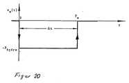
- the basis for fillingare the standard values of phlebology. Because of the relationship between t EL and t EF, these values can be extended to emptying and generally characterize the micro-macro vessel state. 20 shows the system input variable "hydrostatic pressure".
- the system testis advantageously repeated approximately two to three times in succession.
- 23a and 23billustrate a simultaneous measurement of the microcirculation function x micro (t) in a diabetic in the advanced state according to a) on the right index finger and b) on the right big toe.
- FIGS. 24a and 24bshow the associated autocorrelation curves from the measured values in FIGS. 23a and 23b.
- the AKF on the index fingershows a falling tendency, from which it can be seen that the microcirculation function contains biosignals.
- Fig. 24bit is clear that the microcirculation signal contains a large non-periodic portion (range 0 ⁇ ⁇ 1 s), but only a weak periodic microcirculation as the cause of the walking difficulties.
- microvascular system connected to the macro vesselsie the microcirculation functional unit
- the microcirculation functional unitpresents itself as a system with an arterial inflow, a venous outflow and a memory.
- the arterial blood inflow into the arteriolescan be determined by the venous blood outflow from the microvascular system which is directly caused thereby.
- pulsed NIR and red radiation of a medium intensitycan be introduced into the tissue in multiplex mode, which means that, due to the low scattering and absorption in the tissue, relatively large tissue volumes can be evaluated without harmful repercussions.
- the dynamic system status and thus also the amount stored per unit of timecan be determined.
- a practical implementationcan be carried out according to an embodiment of the invention in that a double sensor is attached, for example to the toe or a finger of a subject.
- This double sensorenables multiplex operation for simultaneous red and NIR photoplethysmography at the same time and place.
- a step function in the form of a negative and positive hydrostatic pressurecan be applied to the periphery to be examined and the emptying and filling of the microcirculation functional unit and the resulting ones dynamic jump transition functions can be determined.
- Characteristic system parameterscan be derived from this, which enable a simple evaluation of the state, as is shown in FIG. 26a.
- 26bshows a quantitative course of the arterial inflow and venous outflow within the functional unit of the microcirculation, recorded with the aforementioned implementation variant of a double sensor in multiplex operation.
- test variable hydrostatic pressure applied to the microvascular systemis particularly advantageous.
- This test sizecan be used reproducibly, non-invasively and quantitatively clearly defined.
- the hydrostatic pressure as a quantity caused by the gravitational forceis only dependent on the height in, for example, cm water column and the area on which this water column stands.
- the assessment of a disturbed arterial inflow from the macrovesselsfor example as a result of arteriosclerotic obliterations, as well as statements about the venous outflow from the microvascular system, including venous outflow disorders in the macrog vessels, such as venous thrombosis and venous valve insufficiency, can be made.
- Another area of applicationis the simultaneous red and NIR photoplethysmography for the differentiated assessment of the effect of pharmaceuticals or drugs on the microvascular system under consideration, for example the vasomotor responsiveness of the microvessels.
- the principle of determining the microcirculation and the method of the jump transition functioncan be transferred to the macrovessels (arteries, veins) by detecting the change in flow velocity over time when an appropriate hydrostatic pressure is applied, for example by means of dynamic ultrasound Doppler, i.e. also characteristic time values derived from it.
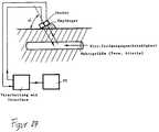
- Fig. 27the basic structure of a dynamic Doppler is shown, from which it can be seen that the transmitter / receiver are separated from the processing electronics because of the minimal size and in a separate, for. B.Clamp sensor housing can be integrated.
- a complex methodresults with the following steps. First, the clamp red NIR sensor is positioned at the patient's starting position (e.g. on the big toe) at a constant room temperature. Approximately a hydrostatic pressure of 0 occurs there. The microcirculation is then measured and a negative and positive hydrostatic pressure jump created. From the course of the jump transition functions for emptying and filling the vessels, it can now be determined whether there are normal values or deviating courses. If the course is normal, the evaluation can be ended. In the event of deviations, it must be determined whether these are in the arterial or venous.
- a continuation of the examinationis carried out specifically with a dynamic ultrasound Doppler, in that the Doppler is fixed at the corresponding measuring point.
- the flow velocity measurementis now not, as is known, purely stationary, but dynamic.
- the dynamic DopplerWith the dynamic Doppler, the jump transition functions and, analogously to the microcirculation measurement, the dynamic system parameters of the corresponding macro vessel are determined in the time domain. A negative and positive hydrostatic pressure jump is also created for this, but a hydrodynamic pressure jump is also possible. It is advantageous to start with the examination and localization of the system with the largest vessels (vein, artery) in order to keep the effort low.
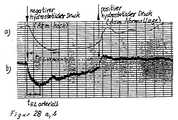
- the Doppler jump transition functions determined in the macro rangeare similar in principle to the curves obtained in the micro range with red or NIR photoplethysmography. Transitional functions occur differently in the arterial area than in the venous macro area, so that it is immediately apparent whether there is an artery or a vein and whether the course is normal or abnormal. This is shown by way of example with FIG. 28, which shows practical measurement results for the left arm of a test subject, with 28a showing a venous jump function recorded with a dynamic ultrasound Doppler and 28b such an arterial jump transition function.
- CMMD 2is a computer-aided device for determining the macro and micro circulation of the vascular system.
- This devicehas at least one NIR sensor and one ultrasound Doppler sensor as a sensor module. The measurement results are then separated Channels provided and processed with the program system CMMD.
- the main features of the program systemare outlined in the versions 1-4 in the lower part of the picture.
- the method according to the inventionfor determining the state of vascular systems on the basis of micro- and macrocirculation processes, it is achieved that an increased amount of information can be obtained from essentially unchanged output data with, however, reduced expenditure on equipment, while avoiding a complex movement program.
- the amount of informationis prepared in such a way that the diagnosing physician is able to easily associate the results obtained with typical disease courses or clinical pictures.
- the above methoddiffers fundamentally from known solutions which are based on data reduction or the known principle of pattern recognition. A simple, clear classification of the results obtained is possible through empirically found and statistically determined relationships.
- the method according to the inventionalso makes it possible to proceed from a rough classification in the sense of an expansion of the diagnosis in a graduated form to a fine classification.
- the diagnosing doctoris given the opportunity to selectively increase or decrease the amount of information available, depending on the specific situation or the condition of the patient.
- thisis done by menu-based preparation of a hierarchically structured directory of evaluation modules.
- the method according to the inventionthus enables on the one hand the description of the steady state of the vascular system to be examined on the basis of the determination of the microcirculation and / or the determination of the dynamic behavior of the system to be examined by applying a step function and evaluating the step transition function.
- the location of a possible macro faultcan also be identified.
- the relative blood pressure values and the relative peripheral resistance RPW 1can also be determined with the stationary Doppler measurements because of the evaluation of time parameters in real time for each cardiac period.
Landscapes
- Health & Medical Sciences (AREA)
- Life Sciences & Earth Sciences (AREA)
- General Health & Medical Sciences (AREA)
- Biomedical Technology (AREA)
- Biophysics (AREA)
- Public Health (AREA)
- Pathology (AREA)
- Physics & Mathematics (AREA)
- Engineering & Computer Science (AREA)
- Veterinary Medicine (AREA)
- Heart & Thoracic Surgery (AREA)
- Medical Informatics (AREA)
- Molecular Biology (AREA)
- Surgery (AREA)
- Animal Behavior & Ethology (AREA)
- Cardiology (AREA)
- Physiology (AREA)
- Radiology & Medical Imaging (AREA)
- Hematology (AREA)
- Nuclear Medicine, Radiotherapy & Molecular Imaging (AREA)
- Vascular Medicine (AREA)
- Measuring Pulse, Heart Rate, Blood Pressure Or Blood Flow (AREA)
Abstract
Description
Translated fromGermanDie Erfindung betrifft ein Arbeitsverfahren zum Betreiben und eine Vorrichtung zur Bestimmung und Auswertung des Zustandes von Gefäßsystemen gemäß dem Oberbegriff der Patentansprüche 1 bzw. 33.33. The invention relates to a working method for operating and to a device for determining and evaluating the state of vascular systems according to the preamble of
Es ist bekannt, daß die Blutfülle der Mikrogefäße bestimmten rhythmischen Schwankungen unterliegt. In den letzten Jahren erfolgten umfangreiche Bemühungen, um die komplexen Ursachen dieser zeitlichen Veränderungen zu erkennen und aus diesen diagnostische Schlüsse zu ziehen.
Zur Erfassung der Makro- und Mikrozirkulations-Rhythmik werden auf der Basis optoelektronischer Komponenten, nämlich quasimonochromatischer Lichtquellen und entsprechender Photodetektoren, bestimmte zu untersuchende Hautareale optisch abgetastet, wobei nach erfolgter Gefäßentleerung auf der Basis der Auswertung von reflektiertem Licht auf eine Füllungszunahme in den cutanen Mikrogefäßen geschlossen wird.It is known that the blood in the microvessels is subject to certain rhythmic fluctuations. Extensive efforts have been made in recent years to identify the complex causes of these temporal changes and to draw diagnostic conclusions therefrom.
To record the macro and microcirculation rhythm, based on optoelectronic components, namely quasi-monochromatic light sources and corresponding photodetectors, Certain areas of the skin to be examined are optically scanned, and after the vessel has been emptied, an increase in the filling in the cutaneous microvessels is concluded on the basis of the evaluation of reflected light.
Eine Einrichtung zur Erfassung und Analyse des Durchblutungszustandes der menschlichen Haut ist beispielsweise aus der deutschen Patentschrift DE 33 18 746 C2 bekannt geworden. Die Einrichtung greift auf das Prinzip der Licht-Reflexions-Rheographie (LRR) zurück. Hierbei wird eine Meßeinrichtung verwendet, welche mit einem leichten, an einem zu untersuchenden Hautareal mit doppelt klebenden Folienringen zu befestigenden Meßkopf ausgerüstet ist, wobei der Meßkopf Öffnungen aufweist, in denen ein optischer Strahlungsempfänger und mehrere Strahlungsquellen angeordnet sind und wobei der Strahlungsempfänger und die Strahlungsquellen unmittelbar an der Hautoberfläche liegen. Die Strahlungsquelle emittiert Strahlungen mit einer Wellenlänge im nahen IR-Bereich des Spektrums. Mit einer elektronischen Auswerteschaltung erfolgt ein selektives Erfassen und Aufzeichnen des zeitlichen Verlaufes des reflektierten bzw. zurückgestreuten Strahlungsanteils bei gleichzeitiger Unterdrückung der Volumenpulsationen. Die oben erwähnte Meßeinrichtung ist in der europäischen Patentschrift 0 063 649 B1 offenbart.A device for recording and analyzing the blood supply to human skin has become known, for example, from
Es besteht jedoch ein wesentlicher Nachteil darin, daß die bekannte Auswertung der LRR-Kurven nur einige wenige diagnostisch relevante Aussagen ermöglicht. Durch die bisher ausschließlich subjektive Beurteilung der erhaltenen LRR-Kurven ist die Wahrscheinlichkeit einer Fehlinterpretation hoch.However, there is a major disadvantage in that the known evaluation of the LRR curves enables only a few diagnostically relevant statements. Because the LRR curves obtained have so far been only subjective, the likelihood of misinterpretation is high.
Mit der bereits erwähnten deutschen Patentschrift 33 18 746 sollen die LRR-Signale objektiv und frei von subjektiven Entscheidungen analysiert und neue geeignetere Parameter zur fundierten sicheren Diagnose des Durchblutungszustandes der menschlichen Haut gewonnen werden.With the already mentioned
Hierfür wird vorgeschlagen, das im allgemeinen erhaltene analoge Ausgangssignal in ein digitales Signal umzusetzen und selbiges einer sogenannten Rechenschaltung zuzuführen. Die Rechenschaltung soll dann physikalische Bewertungsparameter für die analogen LRR-Kurven berechnen. Hierfür wird mittels der Rechenschaltung das Ausgangssignal frequenzanalysiert und zusätzlich zur Bestimmung des Amplitudenverlaufes der Kreislaufrhythmik auch die Frequenzzusammensetzung selbiger ermittelt. In ausgewählten Frequenzbereichen erfolgt eine Fourier-Transformation des Ausgangssignales der Meßeinrichtung.
Als Bewertungsparameter wird die Auffüllzeit der Blutgefäße t₀, die Abfallzeit ta von einem Meßwert 90% auf einen Meßwert 10%, und die Halbwertzeit th, d. h. die Zeit, in der ein Abfall von 100% auf 50% erfolgt, bestimmt.For this purpose, it is proposed to convert the generally obtained analog output signal into a digital signal and to supply the same to a so-called arithmetic circuit. The arithmetic circuit should then calculate physical evaluation parameters for the analog LRR curves. For this purpose, the output signal is frequency-analyzed by means of the arithmetic circuit and, in addition to determining the amplitude profile of the circulatory rhythm, the frequency composition thereof is also determined. A Fourier transformation of the output signal of the measuring device takes place in selected frequency ranges.
The filling time of the blood vessels t₀, the fall time ta from a measured
Die Computeranalyse der LRR-Kurven wird bei der bekannten Lösung in vier Punkten zusammengefaßt. Es werden zunächst die Ergebnisse der Berechnung der venösen Auffüllphase ausgegeben. Neben der Bestimmung der Auffüllzeit t₀ werden die von den störanfälligen Randbedingungen befreite Abfallzeit ta, die bereits erwähnte Halbwertzeit und weitere Parameter berechnet. Danach erfolgt anhand der Amplitudenwerte der gespeicherten LRR-Kurve die Berechnung der Druckdifferenz durch das Auffüllen der Gefäße und bei Belastung. Als Bewertungsparameter wird weiterhin die Fläche unter der LRR-Kurve oder die Steilheit der Auffüllphase zur Diagnose des Zustandes der venösen Hämodynamik herangezogen.The computer analysis of the LRR curves is summarized in four points in the known solution. The results of the calculation of the venous filling phase are output first. In addition to the determination of the filling time t₀, the fall time ta , which is free from the fault-prone boundary conditions, the half-life already mentioned and other parameters are calculated. Then, using the amplitude values of the stored LRR curve, the pressure difference is calculated by filling the vessels and under load. The area under the LRR curve or the steepness of the filling phase for diagnosis of the state of the venous hemodynamics are also used as evaluation parameters.
Durch die Möglichkeit des Transfers der Meßergebnisse aus dem Zeit- in den Frequenzbereich und Ausgabe eines Amplitudendichte-Spektrums mit der Angabe bestimmter Amplitudenfaktoren des Fourier-Spektrums sollen weitere Ansatzpunkte zur Verbesserung der Diagnostik gegeben sein.The possibility of transferring the measurement results from the time domain to the frequency domain and outputting an amplitude density spectrum with the specification of certain amplitude factors of the Fourier spectrum should provide further starting points for improving the diagnosis.
Mit der vorstehend skizzierten Lösung wird es zwar möglich, die erhaltene Informationsmenge aus der LRR-Untersuchung zu vergrößern und eine Vielzahl von Einzelmeßergebnissen bereitzustellen, jedoch wird durch das Prinzip der rechnergestützten Mustererkennung oder den Datentransfer in die Frequenzdomäne die Auswertung für den behandelnden Arzt, der in der Lage sein muß, schnell und mit hoher Treffsicherheit in der täglichen Praxis zu diagnostizieren, nicht erleichtert.
Die zugrundegelegten Auswerteparameter sind für eine gesicherte Diagnose nicht ausreichend.The solution outlined above makes it possible to increase the amount of information obtained from the LRR examination and to provide a large number of individual measurement results, however, the principle of computer-aided pattern recognition or data transfer into the frequency domain does not facilitate the evaluation for the attending physician, who must be able to diagnose quickly and with high accuracy in daily practice.
The underlying evaluation parameters are not sufficient for a reliable diagnosis.
Die Aufgabe der Erfindung besteht daher darin, ein Arbeitsverfahren zum Betreiben und eine Vorrichtung zur Bestimmung und Auswertung des Zustandes von Makro- und Mikrogefäßsystemen auf der Basis einer qualitativ neuen Photoplethysmographie anzugeben, wobei der klinische Informationsgehalt der erfaßten Biosignale wesentlich erhöht und eine umfassende relevante Zuordnung von statistisch gesicherten Merkmalsänderungen zu entsprechenden pathophysischen und klinischen Zuständen möglich werden.The object of the invention is therefore to provide a working method for operating and a device for determining and evaluating the state of macro and micro vessel systems on the basis of a qualitatively new photoplethysmography, the clinical information content of the detected bio-signals being significantly increased and a comprehensive relevant assignment of statistically verified changes in characteristics to corresponding pathophysical and clinical conditions are possible.
Die Lösung der erfindungsgemäßen Aufgabenstellung erfolgt mit den Merkmalen der Patentansprüche 1, 18, 19, 23, 25, 33, 35, 36 und 39, wobei die Unteransprüche zweckmäßige Ausgestaltungen und Weiterbildungen der Erfindung zeigen.The problem of the invention is solved with the features of
Die Erfindung geht dabei von dem Grundgedanken aus, daß es möglich ist, das dynamische Verhalten eines linearen Systems dadurch zu ermitteln, daß das zu untersuchende System mit einer definierten Eingangsfunktion xe(t), wobei diese zum Beispiel eine Sprung- oder Deltafunktion sein kann, beaufschlagt wird. Als Ergebnis oder Wirkung xa(t) erhält man am Systemausgang eine typische Sprung- bzw. Stoßübergangsfunktion. Diese Funktion charakterisiert das dynamische Systemverhalten. Zweckmäßigerweise werden hierbei im allgemeinen dimensionslose bzw. normierte Größen angestrebt. Das dynamische Verhalten der Sprungantwort bzw. Ausgangsgroße xa(t) läßt sich durch Kennwerte, die man aus dem Funktionsverlauf von xa(t) ableiten kann, beschreiben. Typisch ist zum Beispiel die Einschwingzeit tE. Es wurde erkannt, daß solche zu beschreibenden Signale und Systeme näherungsweise auch im Fall der Biomedizin, d. h. bei der Makro- und Mikrozirkulation in Blutgefäßen, vorliegen. Es wurde gefunden, daß das dynamische Verhalten photoplethysmographisch gewonnener Volumenpulse ein Ausdruck derartiger Funktionen ist. Vorteilhafterweise wird ein negativer und anschließend ein positiver Sprung erzeugt, wobei die Sprünge zu einer Entleerung bzw. Füllen des Gefäßsystems führen.The invention is based on the basic idea that it is possible to determine the dynamic behavior of a linear system in that the system to be examined has a defined input function xe (t), which can be, for example, a step or delta function , is applied. As a result or effect xa (t), a typical jump or shock transition function is obtained at the system output. This function characterizes the dynamic system behavior. Appropriately, dimensionless or standardized variables are expediently sought. The dynamic behavior of the step response or output variable xa (t) can be described by characteristic values which can be derived from the function curve of xa (t). The settling time tE is typical, for example. It was recognized that such signals to be described and Systems approximately also exist in the case of biomedicine, ie in the macro and microcirculation in blood vessels. It has been found that the dynamic behavior of volume pulses obtained by photoplethysmography is an expression of such functions. A negative and then a positive jump is advantageously produced, the jumps leading to an emptying or filling of the vascular system.
Erfindungsgemäß wird eine Sprungfunktion durch plötzliche, einmalige Einwirkung, zum Beispiel des plötzlichen Hebens einer Hand oder eines Beines, eines akustischen Signals oder in Form einer druckmechanischen Belastung, ausgelöst. Die Ausgangsgröße des Systems, d. h. des zu untersuchenden peripheren Gebietes, zum Beispiel einer Großzehe, stellt sich dann entsprechend dem jeweiligen konkreten Zustand ein.According to the invention, a step function is triggered by sudden, one-time action, for example the sudden lifting of a hand or a leg, an acoustic signal or in the form of a pressure mechanical load. The output size of the system, i. H. of the peripheral area to be examined, for example a big toe, then adjusts itself according to the respective concrete condition.
Es wurde weiterhin erkannt, daß sich bei jedem zu untersuchenden System eine Aussteuerung in bzw. um einen Arbeitspunkt AP ergibt. Dieser Arbeitspunkt AP liegt auf der Systemkennlinie, die sich als Darstellung von xa über xe ergibt.
Hierbei existieren normale bzw. optimale Werte. Von diesen normalen bzw. optimalen Werten wird im Krankheitsfalle abgewichen. Durch einen einfachen Vergleich der normalen bzw. optimalen Werte mit den jeweils aktuell ermittelten Werten läßt sich mit großer Sicherheit der tatsächliche Zustand des untersuchten peripheren Gebietes feststellen.It was also recognized that there is a modulation in or around an operating point AP for each system to be examined. This operating point AP lies on the system characteristic curve, which results as a representation of xa over xe .
Here there are normal or optimal values. Deviations from these normal or optimal values are made in the event of illness. By simply comparing the normal or optimal values with the currently determined values, the actual state of the examined peripheral area can be determined with great certainty.
Es wurde gefunden, daß sich bei der Mikrozirkulation im Sinne der Chaos-Theorie eine Grundordnung, d. h. ein Arbeitspunkt, einstellt. Daneben besteht determiniertes Chaos. Um den Arbeitspunkt zu bestimmen, wird im stationären Zustand des zu untersuchenden Systems über eine bestimmte Meßzeit die Mikrozirkulation ermittelt.It has been found that microcirculation in the sense of chaos theory has a basic order, i. H. a working point. There is also determined chaos. In order to determine the operating point, the microcirculation is determined in the stationary state of the system to be examined over a certain measuring time.
Bereits hieraus läßt sich erfindungsgemäß schlußfolgen, daß zum Beispiel aus der Analyse der Streubreite der Herzfrequenz erkannt werden kann, ob ein Nichtnormalzustand vorliegt. Es wurde erkannt, daß je kleiner die Streubreite der Herzfrequenz, je größer die Gefährdung oder die potentielle Wahrscheinlichkeit einer Erkrankung ist.From this it can already be concluded according to the invention that, for example, analysis of the spread of the heart rate can be used to determine whether there is a non-normal condition. It It was recognized that the smaller the spread of the heart rate, the greater the risk or the potential probability of an illness.
Durch die vorstehend beschriebene Verfahrensweise lassen sich dann unmittelbar und ohne subjektive Einflußnahme des Probanden oder eines Dritten beispielsweise Auswirkungen von Pharmaka oder Drogen feststellen.The procedure described above can then be used to determine, for example, the effects of pharmaceuticals or drugs directly and without subjective influence from the subject or a third party.
Es liegt im Sinne der Erfindung, daß das Arbeitsverfahren zum Betreiben einer Vorrichtung zur Bestimmung und Auswertung des Zustandes von Gefäßsystemen bei turnusmäßigen Flugtauglichkeitsuntersuchungen oder ähnlichen Tauglichkeitsuntersuchungen angewendet werden kann. Darüber hinaus besteht die Möglichkeit, durch eine periodische oder kontinuierliche Anbordüberwachung z. B. eines Flugzeugführers oder im Weltraumeinsatz die Leistungsfähigkeit des Gefäßsystems und damit den physischen Zustand des Flugzeugführers bzw. des Probanden zu bewerten. Diese Bewertung erfolgt objektiv. Aus der Bewertung können bereits vor dem subjektiven Empfinden eingeschränkter Leistungsfähigkeit Maßnahmen zur Vermeidung von Havarien und von Fehlbedienungen aufgrund eingeschränkter Reaktionsfähigkeit eingeleitet werden.It is within the meaning of the invention that the working method for operating a device for determining and evaluating the state of vascular systems can be used in regular flight fitness examinations or similar fitness examinations. In addition, there is the option of periodic or continuous on-board monitoring such. B. an aircraft pilot or in space use to evaluate the performance of the vascular system and thus the physical condition of the pilot or the subject. This evaluation is done objectively. Measures to avoid accidents and incorrect operation due to limited responsiveness can be initiated from the evaluation before the subjective perception of limited performance.
So ist z.B. der Beginn des Herztodes gekennzeichnet durch den Übergang von einem irregulären Muster der Herztätigkeit zu einem einfachen Muster.
Aus der Analyse der Mikrozirkulation in einem periphären Gebiet (Geweberegion) ist es daher möglich, durch einfache Überwachung der Kontinuität oder Diskontinuität der Herztätigkeit bzw. der Herzfrequenz eine Herzerkrankung festzustellen oder einen bevorstehenden Herzstillstand rechtzeitig zu erkennen.For example, the onset of cardiac death is characterized by the transition from an irregular pattern of cardiac activity to a simple pattern.
From the analysis of the microcirculation in a peripheral area (tissue region) it is therefore possible, by simply monitoring the continuity or discontinuity of the cardiac activity or the heart rate, to determine a heart disease or to recognize imminent cardiac arrest in good time.
Erfindungsgemäß läßt sich die photoplethysmographisch ermittelte integrale Gesamt-Volumenpulsation für das jeweilige ausgeleuchtete periphere Gebiet wie folgt beschreiben:
Dabei bedeuten:
- xges(t), xmikro(t):
- integrale Gesamt-Volumenpulsation des photoplethysmographisch untersuchten peripheren Gebietes (Mikrozirkulationsfunktion)
- xI(t):
- Welle I. Ordnung, verbunden mit der Herzfrequenz als Trägerfrequenz der Mikrozirkulation
- xII(t):
- Welle II. Ordnung, verbunden mit der Atmung
- xIII(t):
- Welle III. Ordnung, verbunden mit der Blutdruckperiode (ca 10 s - Rhythmus)
- xN(t):
- Wellen N-ter Ordnung (bis hin zu mehrtägigen Schwankungen).
Here mean:
- xtotal (t), xmicro (t):
- integral total volume pulsation of the peripheral area examined by photoplethysmography (microcirculation function)
- xI (t):
- First order wave, connected to the heart rate as the carrier frequency of the microcirculation
- xII (t):
- Second-order wave associated with breathing
- xIII (t):
- Wave III. Order, connected with the blood pressure period (approx. 10 s - rhythm)
- xN (t):
- N order waves (up to fluctuations of several days).
Es wurde erkannt, daß alle oben erwähnten Teil-Funktionen den Gesetzen des determinierten Chaos unterliegen.
Das erfindungsgemäße Verfahren auf der Basis der Auswertung von Mikro- und Makrozirkulationsvorgängen in Blutgefäßen geht aufgrund der oben geschilderten Erkenntnisse von der stochastischen Funktion xges(t) im Zeitbereich aus.It was recognized that all of the partial functions mentioned above are subject to the laws of determined chaos.
The method according to the invention, based on the evaluation of micro and macro circulation processes in blood vessels, is based on the above-described knowledge of the stochastic function xtot (t) in the time domain.
Das bereits erwähnte Maß xI(t) für die Wellen I. Ordnung enthält die "Trägerfrequenz" der Mikrozirkulationsfunktion, die Herzfrequenz (Herzperiodendauer TI). Um einen solchen Arbeitspunkt TI wird ausgesteuert, wobei die Streuung ST auftritt. Ein einfacheres Herzrhythmusmuster bedeutet, daß die Streuung ST immer mehr abnimmt und der Arbeitspunkt sich außerhalb des optimalen Bereiches befindet. Im Sinne des erfindungsgemäßen Verfahrens sind daher der Arbeitspunkt und die Streuung für den sogenannten Normalfall in Abhängigkeit vom jeweiligen Lebensalter sowie das mögliche Optimum zu ermitteln und für die weitere Auswertung als Vergleichswerte oder in Form einer Normalkennlinie abzuspeichern.The measure xI (t) for the waves of the 1st order already mentioned contains the "carrier frequency" of the microcirculation function, the heart rate (cardiac period TI ). At such an operating point TI is modulated, the scatter ST occurring. A simpler cardiac rhythm pattern means that the scatter ST decreases more and more and the working point is outside the optimal range. For the purposes of the method according to the invention, the working point and the scatter are therefore to determine the so-called normal case depending on the respective age as well as the possible optimum and to save it for further evaluation as comparison values or in the form of a normal characteristic curve.
In einer Ausführungsform der Erfindung läßt sich die Funktion XI(t) aus xges(t) durch einen Bandpaß mit einer Grenzfrequenz 0,6 Hz < f < 9 Hz ausblenden, trennen und darstellen.In one embodiment of the invention, the function XI (t) from xtot (t) can be hidden, separated and represented by a bandpass filter with a cut-off frequency of 0.6 Hz <f <9 Hz.
Das Maß für die Wellen höherer Ordnung läßt sich mit xbio(t) zusammenfassen.
Diese Wellen höherer Ordnung, die langwellig sind, lassen sich ebenfalls aus xges(t) durch einen Tiefpaß bzw. Bandpaß mit einer oberen Grenzfrequenz fg von ungefähr 0,5 ... 0,6 Hz ausfiltern.The measure for the higher order waves can be summarized with xbio (t).
These higher-order waves, which are long-wave, can also be filtered out of xges (t) by a low-pass filter or bandpass filter with an upper cut-off frequency fg of approximately 0.5 ... 0.6 Hz.
Aus dem konkreten Verlauf xI(t) sind nun eine Vielzahl von Parametern, einschließlich der erwähnten Streuungen S, ermittelbar.
So wird eine Gipfelamplitude A, eine Dikrotieamplitude B, eine Gipfelzeit TG, eine Dikrotiezeit TD, eine arterielle Grundschwingung TAG und eine Pulsperiodenzeit (Herzperiodendauer) TI von xI(t) ermittelt.
Erfindungsgemäß wurde erkannt, daß ein optimaler Arbeitspunkt für den gesunden Menschen bei folgenden Verhältnissen vorliegt:
TD/TI = 0,5
TG/TI = 0,191
TAG/TI = 0,309 sowie
TAG/TD = 0,618
TG/TD = 0,382.A large number of parameters, including the aforementioned scattering S, can now be determined from the specific profile xI (t).
Thus, a peak amplitude A, a dicrotic amplitude B, a peak time TG , a dicrotic time TD , an arterial fundamental vibration TAG and a pulse period (cardiac period) TI of xI (t) are determined.
According to the invention, it was recognized that there is an optimal working point for healthy people under the following conditions:
TD / TI = 0.5
TG / TI = 0.191
TAG / TI = 0.309 as well
TAG / TD = 0.618
TG / TD = 0.382.
Das ideale Amplitudenverhältnis AV im Arbeitspunkt ergibt sich nach der Beziehung:
The ideal amplitude ratio AV at the operating point results from the relationship:
Mit den erwähnten Beziehungen läßt sich im Sinne der Vereinfachung des Auswerteverfahrens ein Optimum in Form eines Merkmalvektors definieren.With the relationships mentioned, an optimum in the form of a feature vector can be defined in the sense of simplifying the evaluation method.
Da Amplitudenwerte der photoplethysmographisch ermittelten Mikrozirkulation von verschiedenen Faktoren abhängig sind, wird erfindungsgemäß die Gleichwertigkeit der Zeitkennwerte bei der Volumenpulsation erkannt. Damit wird eine qualitativ und quantitativ neue Photoplethsymographie, eine zeitdiskrete Photoplethsymographie, geschaffen und der klinische Informationsgehalt beträchtlich erhöht, da die Zeitkennwerte TI, TD, TG, TAG weitgehend unabhängig von Andruck sind und eine Eichung entfällt. Aus Gründen der Vergleichbarkeit wird auf eine Normierung (z. B. auf Herzperiodendauer TI) orientiert.Since the amplitude values of the microcirculation determined by photoplethysmography are dependent on various factors, the equivalence of the time parameters in the case of volume pulsation is recognized according to the invention. This creates a qualitatively and quantitatively new photoplethsymography, a time-discrete photoplethsymography, and considerably increases the clinical information content, since the time parameters TI , TD , TG , TAG are largely independent of pressure and calibration is not necessary. For reasons of comparability, standardization is used (e.g. cardiac period TI ).
Es besteht nun ein weiterer Grundgedanke der Erfindung darin, bestimmte Merkmalsvektoren bestimmten Krankheitsbildern zuzuordnen. Hierfür werden erfindungsgemäße Bewertungskriterien aufgestellt, die eine optimale Entscheidungsfindung ermöglichen.There is now a further basic idea of the invention is to assign certain feature vectors to certain clinical pictures. For this purpose, evaluation criteria according to the invention are set up which enable optimal decision-making.
Zur Erhöhung der Sicherheit gegenüber Störungen bei der Ermittlung der Mikrozirkulationsfunktionen werden erfindungsgemäß fehlererkennende und fehlerkorrigierende Codes angewendet. Grundsätzlich wird hierbei eine zusätzliche Redundanz in den jeweiligen Code eingebaut.
Ein fehlerkorrigierendes Verfahren besteht darin, diese Redundanz dadurch zu realisieren, daß die jeweiligen Bewertungen wiederholt und deren Ergebnisse verglichen werden. Bei Übereinstimmung ist kein Fehler vorhanden, bei Nichtübereinstimmung wird eine nochmalige Wiederholung durchgeführt, wobei mit großer Wahrscheinlichkeit die zwei übereinstimmenden Codewörter (Kennwerte) als richtiges Codewort erkannt und damit eine Fehlerkorrektur ermöglicht werden kann.In order to increase the security against disturbances when determining the microcirculation functions, error-detecting and error-correcting codes are used according to the invention. Basically, additional redundancy is built into the respective code.
A method of correcting errors consists in realizing this redundancy by repeating the respective evaluations and comparing their results. If there is a match, there is no error; if there is a mismatch, a repeated repetition is carried out, it being very likely that the two matching code words (characteristic values) are recognized as the correct code word, and error correction can thus be made possible.
In einer weiteren Ausführungsform der Erfindung wird erkannt, daß sich das komplexe System des Blutkreislaufs im Sinne eines Modells auf den Grundstromkreis der Elektrotechnik zurückführen läßt und somit das Zusammenwirken des Herzens mit dem gesamten Blutkreislaufsystem einschließlich Peripherie durch eine Spannungsquelle E, einem zugehörigen Innenwiderstand Ri und einen Verbraucher (Belastungswiderstand) Ra modellierbar ist. Dabei wird das Maximum der vom Herzen in die Peripherie (Fuktionseinheit Mikrozirkulation) übertragenen Leistung dann erreicht, wenn der Innenwiderstand Ri und der Belastungswiderstand Ra gleich groß sind, d. h.
In a further embodiment of the invention it is recognized that the complex system of the blood circulation in the sense of a Model can be traced back to the basic circuit of electrical engineering and thus the interaction of the heart with the entire blood circulation system including periphery can be modeled by a voltage source E, an associated internal resistance Ri and a consumer (load resistance) Ra . The maximum of the power transmitted from the heart to the periphery (microcirculation functional unit) is reached when the internal resistance Ri and the load resistance Ra are equal, ie
Dieses Optimum wird als Anpassung bezeichnet. Ist Ri > Ra, liegt eine Unteranpassung, bei Ri < Ra eine Überanpassung vor, so daß eine entsprechend geringere Leistung übertragen wird. Aus diesem Modell werden erfindungsgemäß als Innenwiderstand Ri der "relative periphere Widerstand" RPW₁ eingeführt, der näherungsweise das Verhältnis von systolischem zu diastolischem Blutdruck PS und PD darstellt:
This optimum is called adjustment. If Ri > Ra , there is an underfitting, if Ri <Ra there is an overfitting, so that a correspondingly lower power is transmitted. From this model, the "relative peripheral resistance"
Es wurde erfindungsgemäß des weiteren erkannt, daß dieser dimensionslose Widerstand einen optimalen Wert (Norm-Wert) besitzt
und

wobei TB die systolische Gipfelzeit im Blutdruckverlauf, TA die Abfallzeit zwischen dem systolischen Gipfel und der dikroten Einkerbung (Inzisur) darstellen. Somit können erfindungsgemäß im Echtzeitverfahren für jede Herzperiode durch Messung der Zeitkennwerte TB, TA z. B. mittels Ultraschalldopplerverfahren die relativen Blutdruckwerte sowie der relative periphere Widerstand


woraus sich der Mittelwert ergibt:
and
where TB represents the systolic peak time in the blood pressure curve, TA the fall time between the systolic peak and the dicrotic notch (incisor). Thus, according to the invention, in real time for each cardiac period by measuring the time parameters TB , TA z. B. by means of ultrasound Doppler the relative blood pressure values and the relative peripheral resistance
from which the mean results:
Erfindungsgemäß wurde aus dem zugrundeliegenden Modell erkannt, daß als ein "relativer peripherer Widerstand" RPW₂ aus jedem Volumenpuls n abgeleitet werden kann:
wenn TG die Gipfelzeit, TD die Dikrotiezeit und TAG die arterielle Grundschwingung einer Volumenpulsperiode darstellen. Als Mittelwert


if TG is the peak time, TD is the dicrotic time and TAG is the arterial fundamental wave of a volume pulse period. As an average
Überraschenderweise erhält man als Optimum bzw. Norm-Wert analog zu RPW₁
Surprisingly, the optimum or norm value is obtained analogously to
Erfindungsgemäß wird nun erkannt, daß der im Blutkreislauf (Grundstromkreis) sich einstellende relative mittlere (Blut-) Stromfluß nach der allgemeinen Beziehung
verläuft, wobei Irel opt = 1 mit


einstellt. Dann gilt
runs, where Irel opt = 1 with
sets. Then applies
Als Sollwert für die Herzperiodendauer TH wurde erfindungsgemäß dabei der Zusammenhang erkannt, daß
wobei die Differenz [TH IST - TH SOLL] unter Beachtung der Aussteuerungsschranken für PS und PD für eine einzuleitende Therapie (Veränderung des Herzminutenvolumens als Produkt von Schlagvolumen und Herzfrequenz) zugrunde zu legen ist.
In einer weiteren Ausführungsform der Erfindung beruht das Verfahren zur Auswertung von Mikro- und Makrozirkulationsvorgängen in Blutgefäßen auf einer Darstellung der aus xges(t) abgeleiteten verallgemeinerten Mittelwertfunktion: der Autokorrelationsfunktion ψxges(τ). Zusätzlich wird ein sogenannter Mikrozirkulationsgradient Mmikro und eine Kreuzkorrelationsfunktion ψxy(τ) für zwei Mikrozirkulationssignale eingeführt.According to the invention, the relationship was recognized as the target value for the cardiac period TH that
taking the difference [TH ACTUAL - TH TARGET ] taking into account the modulation limits for PS and PD for a therapy to be initiated (change in cardiac output as a product of stroke volume and heart rate).
In a further embodiment of the invention, the method for evaluating micro and macro circulation processes in blood vessels is based on a representation of the generalized average function derived from xtot (t): the autocorrelation function ψxges (τ). In addition, a so-called microcirculation gradient Mmicro and a cross-correlation function ψxy (τ) for two microcirculation signals are introduced.
Es wird zunächst analysiert, wie in xges(t) die Wellen verschiedener Ordnung xI(t), xII(t), xIII(t) anteilig im statistischen Mittel enthalten sind und welche mittleren Perioden auftreten.It is first analyzed how the waves of different orders xI (t), xII (t), xIII (t) are included in xtot (t) in the statistical average and which average periods occur.
Hieraus wird erfindungsgemäß jeweils eine Autokorrelationsfunktion (AKF) (für die Teilfunktionen xI(t), xII(t), xIII(t)) gebildet unter der Annahme, daß die Wellen N-ter Ordnung statistisch voneinander unabhängig sind. Es ergibt sich hieraus die Beziehung:
wobei ψxges(τ) die Autokorrelationsfunktion der integralen Gesamtvolumenpulsation darstellt. Allgemein liegt erfindungsgemäß die mittlere Periode von ψxI(τ) im Bereich 0,7 ... 1,3 s, die von ψxII(τ) im Intervall 3 ... 5 s, und von ψxIII(τ) im Bereich von ca. 10 ... 15 s.
Bei zeitlich entsprechend langen Meßsignalen für xges(t) kann von einem stationären stochastischen Signal ausgegangen werden. Bei einer Signalwiederholung wird sich daher eine gleiche, typische Autokorrelationsfunktion ψxges(τ) ergeben.From this, according to the invention, an autocorrelation function (AKF) (for the subfunctions xI (t), xII (t), xIII (t)) is formed on the assumption that the N-th order waves are statistically independent of one another. This gives the relationship:
whereges xges (τ) represents the autocorrelation function of the integral total volumepulsation . In general, according to the invention, the mean period of ψxI (τ) is in the range 0.7 ... 1.3 s, that of ψxII (τ) is in the
With a correspondingly long time for measurement signals xtot (t) can be assumed by a stationary stochastic signal. In the case of a signalrepetition, the same, typical autocorrelation function ψxges (τ) will result.
Ebenso läßt sich darstellen:
mit ψxbio(τ) als Autokorrelationsfunktion der Bio-Periodik.It can also be represented:
with ψxbio (τ) as an autocorrelation function of the bio-periodic.
Zur Auswertung wird nunmehr in einfacher Weise die Einhüllende von ψxges(τ) betrachtet, welche bei Vorhandensein von xII(t) und xIII(t) außer in den Maxima und Minima keine Waagerechte bildet, sondern eine entsprechende tangentiale Neigung aufweist. Tritt eine Waagerechte als Tangente auf, ist der Anteil von xbio(t) erfindungsgemäß im statistischen Mittel Null. Erfindungsgemäß wird nunmehr der Mikrozirkulationsgradient Mmikro, welcher aus der Autokorrelationsfunktion ψxges(τ) abgeleitet ist, definiert und zur Auswertung herangezogen.For the evaluation, the envelope of ψxges (τ) is now considered in a simple manner, which, in the presence of xII (t) and xIII (t), does not form a horizontal line except in the maxima and minima, but has a corresponding tangential inclination. If a horizontal occurs as a tangent, the proportion of xbio (t) according to the invention is zero on average. According to the invention will now be Mikrozirkulationsgradient themicro M, which is derived from the autocorrelation function ψxtot (τ), defined and used for evaluation.
Mmikro ergibt sich dabei wie folgt:
Max = Maximum der (nahezu) periodischen Funktion ψxges(τ) und Min = zugehöriges Minimum.Mmicro results as follows:
Max = maximum (almost) periodic function ψxtot (τ) and Min = associated minimum.
Hieraus folgt, daß bei fehlender Zeitfunktion xbio(t) die Teil-AKF ψxbio(τ) = 0 und somit auch Mmikro = 0 ist.
Die konkreten Werte im betrachteten bzw. zu untersuchenden System Mmikro können in einfacher Weise ermittelt und mit statistisch gesicherten, beispielsweise in einer Tabelle gespeicherten Werten bestimmter abormaler Zustände verglichen werden.From this it follows that if there is no time function xbio (t) the partial AKF ψxbio (τ) = 0 and thus Mmicro = 0.
The specific values in the system Mmicro being considered or to be examined can be determined in a simple manner and compared with statistically verified values of certain abnormal states, for example stored in a table.
Analog zur Autokorrelationsfunktion kann auch die Kreuzkorrelationsfunktion als Maß zur Bewertung herangezogen werden. Wird die Kreuzkorrelationsfunktion von den Signalen x₁(t) und x₂(t) zum Beispiel am gleichen Finger oder Zehe, jedoch an den verschiedenen Meßstellen 1 und 2 ermittelt, und wird das Maximum bei τ = 0 erhalten, so sind die integralen Volumenpulsationen gleich.
Aus der Bestimmung der zeitlichen Lage τopt des Maximums von ψx1x2(τ) läßt sich die mittlere Blutströmungsgeschwindigkeit zwischen zwei Meßstellen in einfacher Weise ableiten.Analogous to the auto-correlation function, the cross-correlation function can also be used as a measure for the evaluation. If the cross correlation function of the signals x₁ (t) and x₂ (t) is determined, for example, on the same finger or toe, but at the
The average blood flow velocity between two measuring points can be derived in a simple manner from the determination of the temporal position τopt of the maximum of ψx1x2 (τ).
Wie bereits eingangs erwähnt, werden erfindungsgemäß zur Ermittlung und Beurteilung des dynamischen Verhaltens des zu untersuchenden Gefäßgebietes definierte Eingangsfunktionen angelegt. Dies kann zum Beispiel durch eine sprung- oder stoßförmig veränderte Andruckkraft eines Sensors zur Erfassung des reflektierten Lichtes im untersuchten Gebiet erfolgen.
Die mit dem Sensor aufgenommene Antwortfunktion bzw. Sprungübergangsfunktion ist nunmehr Ausdruck für das dynamische Verhalten des von der Strahlung durchdrungenen Mikrozirkulations-Gebietes, d.h. der integralen Volumenpulsation der Mikrozirkulation.As already mentioned at the beginning, defined input functions are created according to the invention for determining and assessing the dynamic behavior of the vessel area to be examined. This can be done, for example, by a sudden or sudden change in the pressing force of a sensor for detecting the reflected light in the area under investigation.
The response function or jump transition function recorded with the sensor is now an expression of the dynamic behavior of the microcirculation area penetrated by the radiation, ie the integral volume pulsation of the microcirculation.
Als Eingangsfunktion ist ein positiver oder aber auch ein negativer hydrostatischer Sprung denkbar. Die erhaltene Sprungantwort läßt sich nunmehr in einfacher Weise zur Auswertung heranziehen, indem z.B. nach der Größe der Einschwingzeit tE eine Klassifizierung durchgeführt wird. Damit wird auch bei dieser dynamischen Systemdiagnostik die zeitdiskrete Photoplethsymographie zugrunde gelegt.
Durch das Auslösen eines negativen und positiven hydrostatischen Drucksprungs entfällt das ansonsten erforderliche bekannte, komplizierte Bewegungsprogramm für Probanden bzw. Patienten. Es wird jedoch das Entleeren und daraus eine "Einschwing"- oder "Entleerzeit" tEL des Mikro- und verbundenen Makrogefäßsystems gemessen sowie als Folge des positiven hydrostatischen Drucksprunges das Wiederauffüllen mit der "Einschwing"- oder "Auffüllzeit tEF bestimmt. Es wurde erkannt, daß im Normalfall der Zusammenhang zwischen Entleeren und Füllen gilt
bei Venenklappen-Insuffizienz jedoch die Einschwingzeiten gleich groß sind.A positive or a negative hydrostatic jump is conceivable as an input function. The step response obtained can now be used for evaluation in a simple manner, for example by the size of the settling time tE a classification is carried out. This means that time-discrete photoplethsymography is also used as a basis for this dynamic system diagnosis.
By triggering a negative and positive hydrostatic pressure jump, the otherwise required, complicated exercise program for test subjects or patients is eliminated. However, the emptying and therefrom a "settling" or "emptying time" tEL of the micro and connected macrovascular system is measured and as a result of the positive hydrostatic pressure jump the refilling with the "settling" or "filling time tEF is determined. It was recognized that normally the connection between emptying and filling applies
in the case of venous valve insufficiency, however, the settling times are the same.
Mit einer weiteren Ausführungsform der Erfindung kann die Vasomotorik bestimmt werden.The vasomotor system can be determined with a further embodiment of the invention.
Die Güte der Vasomotorik wird z. B. durch Auslösen eines akustischen Reizes (Stoß) als Eingangsgröße beurteilt. Die erhaltene Antwort xa(t) stellt sich als Stoßübergangsfunktion ein. Die Güte der Vasomotorik wird dann in einfacher Weise daraus ermittelt, indem die Einschwingzeit tE aus der Einhüllenden von xa(t) bestimmt wird. Bei fehlender Vasomotorik erhält man tE = 0. Als Einschwingzeit tE wird die Zeit verstanden, nach der die Antwort auf die Eingangs-Stoßfunktion innerhalb des Bereiches von ± 5% von xa(∞) verbleibt.The quality of the vasomotor is z. B. judged by triggering an acoustic stimulus (shock) as an input variable. The response xa (t) obtained arises as a shock transfer function. The quality of the vasomotor system is then determined in a simple manner by determining the settling time tE from the envelope of xa (t). If the vasomotor system is missing, one obtains tE = 0. The settling time tE is understood to be the time after which the response to the input shock function remains within the range of ± 5% of xa (∞).
Durch eine Auswertung von Zeitkennwerten der Volumenpulsation wird der Informationsgehalt beträchtlich erhöht. In diesem Sinne wurde erfindungsgemäß ein Vasomotorikgradient Mvaso 1 eingeführt.
Als andere mögliche Kenngröße läßt sich aus den Amplitudenverhältnissen der Vasomotorikgradient Mvaso 2 einführen.The information content is increased considerably by evaluating time parameters of the volume pulsation. In this sense, a vasomotorgradient Mvaso 1 was introducedaccording to the invention .
The vasomotorgradient Mvaso 2 can be introduced as another possible parameter from the amplituderelationships .
In einfacher Weise ist eine Klassifizierung von Mvaso in verschiedene Vasomotorik-Stufen möglich.A simple classification of Mvaso into different vasomotor levels is possible.
Die Erfindung soll nun anhand mehrerer Ausführungsbeispiele und von Figuren näher erläutert werden.The invention will now be explained in more detail using several exemplary embodiments and figures.
Hierbei zeigen:
- Fig. 1
- den typischen Verlauf eines photoplethysmographisch ermittelten Mikrozirkulationssignals, bestehend aus den Komponenten xI(t), XII,III(t),
- Fig. 2
- einen Zeitausschnitt einer ermittelten Volumenpulsation mit charakteristischen Parametern,
- Fig. 3 a-c
- in Abhängigkeit vom Lebensalter die qualitativen Normalwerte von normierten Parametern der Volumen pulsation sowie die Verhältnisse im Optimalfall OPT,
- Fig. 4
- den Mikrogefäßzustand als Darstellung der normierten Gipfelzeiten in Abhängigkeit von der normierten Dikrotiezeit und der zugehörigen Klassifizierung sowie den Übergangsbereich UE,
- Fig. 5
- den Blutkreislauf als Grundstromkreis mit Spannungsquelle E (Herz), Innenwiderstand Ri und Verbraucher Ra (Funktionseinheit Mikrozirkulation),
- Fig. 6
- normale und nichtnormale Formen des zentralen Pulses mit den Zeitkennwerten TA, TB
A... normal
B, C, D ... nichtnormal, - Fig. 7
- die Abhängigkeit zwischen systolischem Blutdruck PS und PD mit verschiedenen Werten des relativen peripheren Widerstandes RPW₁ als Parameter, Ruheblutdruckwerten nach E. Stein und Aussteuerungsgrenzen,
- Fig. 8
- eine mit einem Ultraschalldoppler aufgenommene Fließgeschwindigkeit in einer Armarterie einschließlich der charakteristischen Zeitparameter,
- Fig. 9
- den ermittelten relativen peripheren Widerstand RPW₂, Dikrotiezeit TD und arterielle Grundschwingung TAG einschließlich Streubereich bei Zeitparametern in Abhängigkeit des Lebensalters,
- Fig. 10
- den ermittelten peripheren Widerstand RPW₂, Herzperiodendauer

- Fig. 11
- die normierte Verbraucherleistung Pa* in Abhängigkeit der relativen peripheren Widerstände (PA ... Verbraucherleistung, PK ... Leistungsabgabe des Generators bei Kurzschluß),
- Fig. 12 a bis d
- Normalbereiche in Abhängigkeit vom Lebensalter für den Ruheblutdruck (Fig. 12a), daraus abgeleitet RPW₁ (Fig. 12b), für RPW₂ (Fig. 12c) und für den relativen mittleren (Blut-) Stromfluß Irel (Fig. 12d). A, B, D = Meßwerte für Probanden nach Fig. 10.
- Fig. 13 a und b
- eine ermittelte Autokorrelationsfunktion ψxmikro(τ) mit (a) entsprechenden abgeleiteten Kenngrößen und (b) mit stark ausgeprägter Atmungskomponente,
- Fig. 14
- eine prinzipielle Darstellung zur Ermittlung der mittleren Blutströmungsgeschwindigkeit,
- Fig. 15
- die Definition der Einschwingzeit tE,
- Fig. 16
- die Messung der Einschwingzeit zur Beurteilung der Vasomotorik bei einer durch akustische Sympathikusstimulation hervorgerufenen Änderung der Mikrozirkulation (Anzahl der durch die Vasomotorik erfaßten Volumenpulsationen: n = 16; Diagnose: Klasse I/gesund),
- Fig. 17
- prinzipielle Darstellungen zur Ermittlung des Vasomotorikgradienten,
- Fig. 18
- einen Systemtest mit negativem und positivem hydrostatischem Drucksprung,
- Fig. 19
- eine hämodynamische Gradeinteilung für das Entleeren und Füllen der Mikro- und Makrogefäße bei einem Systemtest nach Fig. 18,
- Fig. 20
- eine Darstellung der Systemeingangsgröße hydrostatischer Drucksprung,
- Fig. 21
- praktische Ergebnisse eines Systemtestes "venöses Entleeren und Füllen",
- Fig. 22
- ein Vasolineal,
- Fig. 23
- simultan aufgenommene Mikrozirkulationsfunktionen bei einem Diabetiker im fortgeschrittenen Zustand
- a) am rechten Zeigefinger,
- b) an der rechten Großzehe,
- Fig. 24
- aus den Verläufen nach Fig. 23 ermittelte Autokorrelationsfunktionen
- a) für rechten Zeigefinger,
- b) für rechte Großzehe,
- Fig. 25
- Darstellung der Funktionseinheit Mikrozirkulation,
- Fig. 26 a und b
- den Verlauf des arteriellen Zuflusses, die gespei cherte Mengenveränderung pro Zeiteinheit sowie den venösen Abfluß bei der Funktionseinheit Mikrozirkulation, falls eingangsseitig ein negativer und positiver hydrostatischer Drucksprung angelegt wird,
- a) den qualitativen Verlauf mit entsprechenden Kenngrößen (Pulsationen in der Mikrozirkulation sind nicht dargestellt), insbesondere mit
den Gleichgewichtspunkten GP - b) den bei einem Probanden gemessenen quantitativen Verlauf mit einem Multiplex-Rot/NIR-Dopplersensor,
- a) den qualitativen Verlauf mit entsprechenden Kenngrößen (Pulsationen in der Mikrozirkulation sind nicht dargestellt), insbesondere mit
- Fig. 27
- den prinzipiellen Aufbau eines dynamischen Ultraschall-Dopplers;
- Fig. 28 a und b
- eine mit einem dynamischen Ultraschall-Doppler aufgenommene venöse (a) und arterielle (b) Sprungübergangsfunktion.;
- Fig. 29
- ein Blockschaltbild einer Realisierungsform der Vorrichtung zur Gefäßzustandsbestimmung.

- Fig. 1
- the typical course of a microcirculation signal determined by photoplethysmography, consisting of the components xI (t), XII, III (t),
- Fig. 2
- a time segment of a determined volume pulsation with characteristic parameters,
- Fig. 3 ac
- depending on age, the qualitative normal values of normalized parameters of volume pulsation as well as the optimal conditions, OPT,
- Fig. 4
- the microvessel state as a representation of the normalized peak times depending on the normalized dicrotic time and the associated classification as well as the transition area UE,
- Fig. 5
- the blood circulation as a basic circuit with voltage source E (heart), internal resistance Ri and consumer Ra (functional unit microcirculation),
- Fig. 6
- normal and non-normal forms of the central pulse with the time parameters TA , TB
A ... normal
B, C, D ... abnormal, - Fig. 7
- the dependence between systolic blood pressure PS and PD with different values of the relative
peripheral resistance RPW 1 as parameters, resting blood pressure values according to E. Stein and modulation limits, - Fig. 8
- a flow velocity in an artery, recorded with an ultrasound Doppler, including the characteristic time parameters,
- Fig. 9
- the determined relative peripheral resistance RPW₂, dicrotic time TD and arterial fundamental vibration TAG including the range of variation in time parameters as a function of age,
- Fig. 10
- the determined peripheral resistance RPW₂, cardiac period
- Fig. 11
- the standardized consumer power Pa * as a function of the relative peripheral resistances (PA ... consumer power, PK ... power output of the generator in the event of a short circuit),
- Fig. 12 a to d
- Normal ranges depending on age for resting blood pressure (Fig. 12a), derived from it RPW₁ (Fig. 12b), for RPW₂ (Fig. 12c) and for the relative mean (blood) current flow Irel (Fig. 12d). A, B, D = measured values for test persons according to FIG. 10.
- 13 a and b
- an determined autocorrelation function ψxmicro (τ) with (a) corresponding derived parameters and (b) with a pronounced respiratory component,
- Fig. 14
- a basic representation for determining the mean blood flow velocity,
- Fig. 15
- the definition of the settling time tE ,
- Fig. 16
- the measurement of the settling time to assess the vasomotor system in the event of a change in the microcirculation caused by acoustic sympathetic stimulation (number of volume pulsations detected by the vasomotor system: n = 16; diagnosis: class I / healthy),
- Fig. 17
- basic representations for determining the vasomotor gradient,
- Fig. 18
- a system test with negative and positive hydrostatic pressure jump,
- Fig. 19
- 18 a hemodynamic graduation for emptying and filling the micro and macro vessels in a system test according to FIG. 18,
- Fig. 20
- a representation of the system input variable hydrostatic pressure jump,
- Fig. 21
- practical results of a system test "venous emptying and filling",
- Fig. 22
- a vasolineal,
- Fig. 23
- Simultaneously recorded microcirculation functions in an advanced diabetic
- a) on the right index finger,
- b) on the right big toe,
- Fig. 24
- 23 autocorrelation functions determined from the courses
- a) for right index finger,
- b) for right big toe,
- Fig. 25
- Representation of the microcirculation functional unit,
- 26 a and b
- the course of the arterial inflow, the saved assured change in quantity per unit of time as well as the venous outflow in the microcirculation functional unit, if a negative and positive hydrostatic pressure jump is applied on the input side,
- a) the qualitative course with corresponding parameters (pulsations in the microcirculation are not shown), in particular with the equilibrium points
GP - b) the quantitative course measured in a subject with a multiplex red / NIR Doppler sensor,
- a) the qualitative course with corresponding parameters (pulsations in the microcirculation are not shown), in particular with the equilibrium points
- Fig. 27
- the basic structure of a dynamic ultrasonic Doppler;
- 28 a and b
- a venous (a) and arterial (b) jump transition function recorded with a dynamic ultrasound Doppler .;
- Fig. 29
- a block diagram of a form of implementation of the device for determining the condition of the vessels.
Mit Hilfe der Fig. 1 und 2 soll in einem Ausführungsbeispiel illustriert werden, wie das erfindungsgemäße Verfahren eine Auswertung der stationären, stochastischen Funktion xges (t) im Zeitbereich ermöglicht.
Die Fig. 2 zeigt einen Zeitausschnitt einer ermittelten Volumenpulsation nebst zugehörenden Parametern. Hierbei bedeuten:
- A
- Gipfelamplitude
- B
- Dikrotieamplitude
- TG
- Gipfelzeit
- TD
- Dikrotiezeit
- TAG
- arterielle Grundschwingung und
- TI =TH
- Pulsperiodenzeit von xI(t) (Herzperiodendauer).
2 shows a time segment of a determined volume pulsation along with the associated parameters. Here mean:
- A
- Peak amplitude
- B
- Dicrotoid amplitude
- TG
- Peak time
- TD
- Dicrotism time
- TAG
- basic arterial vibration and
- TI = TH
- Pulse period time of xI (t) (cardiac period).
Alle Parameter besitzen im Sinne der Chaostheorie eine Streuung S, z.B. STI als Streuung von TI.In the sense of chaos theory, all parameters have a scatter S, for example STI as a scatter of TI.
Aus der Fig. 2 geht hervor, daß die entsprechenden Informationen sowohl in der Amplitude als auch in der Zeit enthalten sind.
Die Amplituden des photoplethysmographisch ermittelten Signals haben den Nachteil, daß sie andruckabhängig sind, z.T. von multiplen von außen wenig zu beeinflussenden Faktoren bestimmt werden und kaum eichbar sind. Mit der gleichwertigen Auswertung von Zeitkennwerten wird ein ähnlicher Qualitätssprung wie in der Nachrichtentechnik beim Übergang von der Amplitudenzur Frequenzmodulation erreicht. Um die Ergebnisse verallgemeinern zu können, wird ebenfalls auf relative (bezogene bzw. normierte) Größen orientiert. Zentrale Parameter einer Normierung sind die Herzperiodendauer
The amplitudes of the photoplethysmographically determined signal have the disadvantage that they are pressure-dependent, are determined in part by multiple factors which can hardly be influenced from the outside and are hardly verifiable. With the equivalent evaluation of time parameters, a similar leap in quality as in communications technology is achieved in the transition from amplitudes to frequency modulation. In order to be able to generalize the results, it is also based on relative (related or standardized) quantities. The central parameters of a normalization are the cardiac period
Aus der Analyse einer großen Anzahl von Meßsignalen und der prinzipiellen Darstellung des Verlaufes nach Fig. 2 werden in überraschender Weise als optimale Verhältnisse gefunden TD/TI = 0,5, TG/TI = 0,191 TAG/TI = 0,309; jedoch ebenso B/A = 0,618. Diese Werte stellen ideale Arbeitspunkte dar.
Als allgemeine Grundbeziehung läßt sich des weiteren angeben
From the analysis of a large number of measurement signals and the basic representation of the course according to FIG. 2, surprisingly optimal conditions are found TD / TI = 0.5, TG / TI = 0.191 TAG / TI = 0.309 ; however also B / A = 0.618. These values represent ideal working points.
The general basic relationship can also be given
Mit den Figuren 3a bis 3c werden in Abhängigkeit vom Lebensalter die Normalwerte von normierten Parametern TD/TI, TG/TI, STI/TI sowie die Verhältnisse im Optimalfall OPT illustriert. Es ist anzumerken, daß es sich bei den Darstellungen um normierte Werte handelt. Mit dem Verhältnis TD/TI wird die normierte Dikrotiezeit bezeichnet, mit dem Verhältnis TG/TI die normierte Gipfelzeit und mit dem Verhältnis STI/TI die normierte Streuung der Pulsperiodenzeit.
Die Einordnung von Normalwerten ist deutlich zu erkennen. Die ausgezogenen Linien stellen jeweils die Mittelwertkurve ohne berücksichtigten Streubereich für den gesunden Menschen dar. Die strichpunktierte Linie in den Figuren 3a und 3b repräsentieren das theoretische Optimum OPT.FIGS. 3a to 3c illustrate the normal values of standardized parameters TD / TI , TG / TI , STI / TI and the conditions in the optimal case OPT, depending on the age. It should be noted that the representations are normalized values. The ratio TD / TI denotes the normalized dicrotic time, the ratio TG / TI the normalized peak time and the ratio STI / TI the normalized spread of the pulse period.
The classification of normal values can be clearly seen. The solid lines each represent the mean value curve without consideration of the scatter range for healthy people. The dash-dotted line in FIGS. 3a and 3b represent the theoretical optimum OPT.
Vergleicht man nun tatsächlich ermittelte Werte mit den genannten, zweckmäßigerweise gespeicherten Mittelwertkurven, dann ist es in einfacher Weise möglich, daß der behandelnde Arzt gegebenenfalls typische Krankheitsbilder den tatsächlichen Werten zuordnen kann.If you now compare actually determined values with the above-mentioned, appropriately stored mean value curves, then it is possible in a simple manner that the treating physician can, if necessary, assign typical clinical pictures to the actual values.
Durch die vorgeschlagene Messung der normierten Zeitverhältnisse und die Bestimmung der Streuung bei Berücksichtigung der normierten Amplitudenwerte können ansonsten auftretende Meßfehler eliminiert und die Auswertung dadurch vereinfacht werden.The proposed measurement of the standardized time relationships and the determination of the scattering, taking into account the standardized amplitude values, can eliminate measurement errors that otherwise occur and thus simplify the evaluation.
Zwecks Aufstellung von Bewertungskriterien wurden klinisch gesunde und kranke Probanden (im vorliegenden Fall mikroangioorganische Gefäßveränderungen bei Probanden mit Diabetes mellitus) untersucht. Es wird hierfür ein allgemeiner "Mikrogefäßzustand" für die Abhängigkeit der (normierten) Gipfelzeit TG/TI von der (normierten) Diskrotiezeit TD/TI definiert, wie Fig. 4 illustriert. Den erhaltenen Meßwerten werden die Klassen zugeordnet
- Klasse 1 (Normalwerte),
- Klasse 2 (Nichtnormalwerte, z.B. mikroangioorganische Gefäß veränderungen bei diabetischer Angiopathie).
- Class 1 (normal values),
- Class 2 (non-normal values, e.g. microangio-organic vascular changes in diabetic angiopathy).
Wenn Meßwerte im gekennzeichneten Übergangsbereich UE bestimmt werden, sollte eine Messung im Sinne der Erhöhung der Meßgenauigkeit wiederholt werden. Selbstverständlich ist die Bildung weiterer Unterklassen möglich.If measured values are determined in the marked transition area UE, a measurement should be repeated in the sense of increasing the measuring accuracy. Of course, the formation of further sub-classes is possible.
Wie aus den Fig. 3a und 3b hervorgeht, verhalten sich die normierten Zeitverhältnisse TD/TI und TG/TI in Abhängigkeit vom Lebensalter gerade umgekehrt. Um diesen Alterseinfluß bei Bewertungskriterien nahezu auszugleichen, wird in einem Ausführungsbeispiel der Erfindung nach Fig. 4 ein "integraler Mikrogefäßzustand" MG durch Addition der normierten Parameter eingeführt, so daß ein (dimensionsloser) Wert entsprechender Größe erhalten wird:
Mit den empirisch gefundenen Optima für TG/TI und TD/TI erhält man als optimalen Wert
während bei pathologischen Fällen (z.B. bei mikroangioorganischen Gefäßveränderungen) Werte von MG ≈ 1 auftreten. Folglich ist auch hier eine Klassifizierung in Normalwerte (Klasse 1) und Nichtnormalwerte (Klasse 2) bei Auftreten eines Übergangsbereiches UE in einfacher Weise möglich.As can be seen from FIGS. 3a and 3b, the standardized time relationships TD / TI and TG / TI behave in reverse depending on age. In order to almost compensate for this age influence in evaluation criteria, an "integral microvessel state" MG is introduced in one embodiment of the invention according to FIG. 4 by adding the standardized parameters, so that a (dimensionless) value of corresponding size is obtained:
With the empirically found optima for TG / TI and TD / TI one obtains the optimal value
while in pathological cases (eg in the case of microangioorganic vascular changes) values of MG ≈ 1 occur. Consequently, a classification into normal values (class 1) and non-normal values (class 2) is possible in a simple manner when a transition area UE occurs.
Mit einem weiteren komplexen Ausführungsbeispiel der Erfindung nach Fig. 5 soll gezeigt werden, daß sich der Blutkreislauf als Modell darstellen läßt, bei welchem eine Analogie zum elektrotechnischen Grundstromkreis im Sinne des Zusammenwirkens zwischen Spannungsquelle (Herz) und Peripherie Ra (Widerstandgefäße der Funktionseinheit Mikrozirkulation, wie Fig. 25 zeigt) über den Blutkreislauf betrachtet wird.5 is to show that the blood circulation can be represented as a model in which an analogy to the basic electrical circuit in the sense of the interaction between the voltage source (heart) and the periphery Ra (resistance vessels of the microcirculation functional unit, 25 shows) is considered via the bloodstream.
Aus Fig. 6 geht hervor, daß aus dem zentralen Puls neben der Amplitude die gleichwertigen charakteristischen Zeitkennwerte der systolischen Gipfelzeit TB sowie der Abfallzeit TA zwischen systolischem Gipfel und dikroter Einkerbung ableitbar sind, die ein Maß für den systolischen und diastolischen Blutdruck PS, PD darstellen. Damit läßt sich erfindungsgemäß der relative periphere Widerstand RPW₁ als Ausdruck des im Grundstromkreis wirkenden Innenwiderstandes Ri bestimmen.6 shows that the central pulse in addition to the amplitude, the equivalent characteristic time values of the systolic peak time TB and the fall time TA between the systolic peak and dicrotic notch, which are a measure of the systolic and diastolic blood pressure PS , Represent PD. Thus, according to the invention, the relative
In Fig. 7 ist die Abhängigkeit zwischen systolischem und diastolischem Blutdruck PS, PD mit verschiedenen Werten des relativen peripheren Widerstandes RPW₁ als Parameter, den Ruheblutdruck-Normalwerten einschließlich festgelegten Aussteuerungsgrenzen dargestellt. Es wird deutlich, daß der eingeführte Widerstand RPW₁ ein quantitatives Maß für das Zusammenwirken mit der Peripherie ist.In Fig. 7, the dependence between systolic and diastolic blood pressure PS , PD with different values of the relative peripheral resistance RPW₁ is shown as a parameter, the normal blood pressure values including the fixed modulation limits. It is clear that the
Fig. 8 zeigt dabei eine mit einem Ultraschall-Doppler aufgenommene Fließgeschwindigkeit in einer Armarterie, woraus die charakteristischen Zeitkennwerte TA, TB nach Fig. 6 ebenfalls ableitbar sind.8 shows a flow velocity in an arm artery recorded with an ultrasound Doppler, from which the characteristic time parameters TA , TB according to FIG. 6 can also be derived.
Mit der Fig. 9 wird die Abhängigkeit des erfindungsgemäß definierten relativen peripheren Widerstandes RPW₂, der dem Belastungswiderstand Ra im Grundstromkreis entspricht und für jeden auftretenden Volumenpuls der Mikrozirkulation bestimmt werden kann, in Abhängigkeit des Lebensalters illustriert. Dabei sind ebenfalls die auf diesem Widerstand beruhenden Dikrotiezeiten TD sowie die arterielle Grundschwingung TAG aufgeführt.
Fig. 9a stellt die Verhältnisse bei weiblichen, Fig. 9b bei männlichen Probanden dar. Deutlich zeigt sich die Einordnung des ermittelten optimalen Widerstandes RPW₂opt = 1,618.9 shows the dependency of the relative peripheral resistance RPW₂ defined in accordance with the invention, which corresponds to the load resistance Ra in the basic circuit and can be determined for each volume pulse of the microcirculation that occurs, as a function of age. The dicrotic times TD based on this resistance and the basic arterial vibration TAG are also listed.
Fig. 9a shows the relationships in female, Fig. 9b in male subjects. The classification of the determined optimal resistance RPW₂opt = 1.618 is clearly shown.
Fig. 10 zeigt die konkreten Meßdaten bei drei charakteristischen Probanden, wobei die Werte aus jedem gemessenen Volumenpuls der Mikrozirkulationsfunktionen bestimmt werden.10 shows the concrete measurement data for three characteristic test subjects, the values being determined from each measured volume pulse of the microcirculation functions.
Mit der Fig. 11 wird das optimale Zusammenwirken zwischen Herz und Peripherie im Sinne von Fig. 5 deutlich. Bei
Mit Fig. 12 als weiteres Ausführungsbeispiel der Erfindung werden Normalbereiche in Abhängigkeit vom Lebensalter für den Ruheblutdruck (Fig. 12a), daraus abgeleitet für den relativen peripheren Widerstand

In einem weiteren Ausführungsbeispiel der Erfindung werden zur Auswertung der erhaltenen Informationen aus der Mikrozirkulation die Autokorrelationsfunktionen gebildet.In a further exemplary embodiment of the invention, the autocorrelation functions are formed for evaluating the information obtained from the microcirculation.
In der Fig. 13a und 13b werden Autokorrelationsfunktionen
Es können daraus folgende Rückschlüsse gezogen werden. Die Anteile der Teil-Autokorrelationsfunktionen hängen von den Anteilen der zugehörigen Zeitfunktionen xI(t), xII(t), xIII(t) innerhalb von xges(t) ab. Die Gesamt-Autokorrelationsfunktion stellt sich als eine Überlagerung der Teil-Autokorrelationsfunktionen dar. In Fig. 13a betragen die mittleren Perioden von ψxI(τ) ungefähr 0,75 s, die von ψxIII(τ) ungefähr 14 s; in Fig. 13b die Atmungskomponente ungefähr 5 s. Die Einhüllende von ψxges(τ) muß im Normalfall in einem bestimmten Zeitintervall abfallen und wieder ansteigen, wie die Fig. 13a und 13b zeigen. Als Maß wird ein sogenannter Mikrozirkulationsgradient Mmikro aus ψxges(τ) abgeleitet.
Mmikro ergibt sich aus folgender Beziehung:
wobei mit Max das Maximum der periodischen Funktion ψxges(τ) und mit Min ein zugehöriges Minimum definiert ist (Fig. 13a).13a and 13b are autocorrelation functions
The following conclusions can be drawn from this. The proportions of the partial autocorrelation functions depend on the proportions of the associated time functions xI (t), xII (t), xIII (t) within xtot (t). The total autocorrelation function presents itself as a superposition of the partial autocorrelation functions. In FIG. 13a the mean periods of ψxI (τ) are approximately 0.75 s, those of ψxIII (τ) approximately 14 s; in Fig. 13b the respiratory component for about 5 s. The envelope of ψxges (τ) must normally fall and rise again in a certain time interval, as shown in FIGS. 13a and 13b. A so-called microcirculationgradient Mmicro is derived from ψxges (τ) as a measure.
Mmicro results from the following relationship:
where Maxdefines the maximum of the periodic function ψxges (τ) and Min an associated minimum (Fig. 13a).
Analog zur Autokorrelationsfunktion ist eine Kreuzkorrelationsfunktion ψxy(τ) als Maß für die statistische Abhängigkeit zweier Funktionen x(t) und y(t) bestimmbar. Das Maximum der Kreuzkorrelationsfunktion tritt i. a. nicht bei τ = 0 auf, sondern bei einer mittleren Laufzeit τopt zwischen den gewählten Meßstellen.Analogous to the auto-correlation function, a cross-correlation function ψxy (τ) can be determined as a measure of the statistical dependency of two functions x (t) and y (t). The maximum of the cross-correlation function generally does not occur at τ = 0, but at an average transit time τopt between the selected measuring points.
Wird die Kreuzkorrelationsfunktion ψxy(τ) bei der integralen Volumenpulsation gebildet, zum Beispiel am gleichen Finger mit den Meßstellen 1 und 2, und wird das Maximum bei τ = 0 erhalten, sind die integrale Volumenpulsationen gleich.If the cross-correlation function ψxy (τ) is formed in the case of integral volume pulsation, for example on the same finger with measuring
Mit der Fig. 14 wird illustriert, wie auf der Basis der Kreuzkorrelationsfunktion KKF die mittlere Blutströmungsgeschwindigkeit vström zwischen zwei Meßstellen bestimmt werden kann. Die gezeigten Empfänger E1 und E2 liefern die vom Sender S ausgesendeten und im peripheren Gebiet reflektierten Signale x₁(t) und x₂(t). Die Kreuzkorrelationsfunktion bestimmt sich dann wie folgt:
wobei T die mittlere Laufzeit darstellt, die das Blut braucht, um von Meßstelle E1 zu Meßstelle E2 zu gelangen. Da die Kreuzkorrelationsfunktion das Maximum bei

mit a = Abstand zwischen E1 und E2.With FIG. 14 illustrates how on the basis of the cross correlation function CCF, the mean blood flow velocity v can be determinedStröm between two measuring points. The receivers E1 and E2 shown deliver the signals x 1 (t) and x 2 (t) emitted by the transmitter S and reflected in the peripheral area. The cross correlation function is then determined as follows:
where T represents the average transit time that the blood needs to get from measuring point E1 to measuring point E2. Because the cross correlation function is the maximum at
with a = distance between E1 and E2.
In Ausgestaltung der Erfindung kann beispielsweise die Eingangsgröße an Meßstelle E1 stoßartig verändert werden, indem ein einmaliges, kurzes Husten erfolgt, wodurch ein quasi Nadelimpuls erzeugt wird, welcher sich von der Meßstelle E1 zur Meßstelle E2 fortpflanzt.In an embodiment of the invention, for example, the input variable at measuring point E1 can be abruptly changed by a single, short cough, whereby a quasi needle pulse is generated which propagates from measuring point E1 to measuring point E2.
In der Fig. 15 wird die Definition der Einschwingzeit tE deutlich gemacht; tE ist die Zeit, nach der die Antwort xa(t) auf einen eingangsseitigen Sprung endgültig innerhalb der Schranken von ± 5% von xa(∞) verbleibt. Für den Fall eines sogenannten negativen hydrostatischen Druckprungs am Eingang des Systems wird auf die gleiche Definition zurückgegriffen.The definition of the settling time tE is made clear in FIG. 15; tE is the time after which the response xa (t) to an input-side jump remains within the bounds of ± 5% of xa (∞). In the event of a so-called negative hydrostatic pressure jump at the entrance to the system, the same definition is used.
Analoge Aussagen gelten für eine Stoßfunktion und die zugehörigen Stoßübergangsfunktion.Analogous statements apply to a shock function and the associated shock transfer function.
Es hat sich dabei als vorteilhaft erwiesen, daß für den Erhalt einheitlicher, vergleichbarer Werte für die Einschwingzeiten bei positivem und negativem Sprung Δt ≧ tE ist. Mit anderen Worten muß sich das System bzw. das untersuchte periphere Gebiet in einem eingeschwungenen Zustand befinden, wenn auf den negativen Sprung ein positiver Sprung folgt.It has proven to be advantageous that Δt ≧ tE for obtaining uniform, comparable values for the settling times with positive and negative jump. In other words, the system or the examined peripheral area must be in a steady state if the negative jump is followed by a positive jump.
Wie in der Fig. 16 dargestellt, kann aus der Messung der konkreten Einschwingzeit tE des untersuchten peripheren Gebietes eine Beurteilung der Vasomotorik des Probanden erfolgen. Hierbei wird von der Tatsache ausgegangen, daß die Vasomotorik nicht von der Mikrozirkulation zu trennen und Teil des pulsierenden Systems ist. Es läßt sich also mit anderen Worten die Güte der Vasomotorik durch das Auslösen eines akustischen Reizes (Stoßfunktion) beurteilen. Die Antwort xa(t) hierauf stellt sich als leicht auszuwertende Stoßübergangsfunktion ein. Die Zeit zwischen Reizauslösung bis zum beginnenden Stoßübergang wird mit t₀ bezeichnet (Laufzeit). Die Güte der Vasomotorik kann durch die Aufnahme von xa(t) und der Einschwingzeit tE aus der Einhüllenden von xa(t) gemäß Fig. 17a, b erfolgen.
Bei fehlender Vasomotorik ergibt sich tE = 0. Fig. 17a zeigt vasomotorische Reaktionen bei einem Probanden gemessen am Finger und Fig. 17b die zeitgleich gemessenen Reaktionen an der Großzehe.As shown in FIG. 16, the measurement of the specific settling time tE of the examined peripheral area allows an assessment of the subject's vasomotor system. This is based on the fact that the vasomotor system cannot be separated from the microcirculation and is part of the pulsating system. In other words, the quality of the vasomotor system can be assessed by triggering an acoustic stimulus (impact function). The answer xa (t) to this is an easy-to-evaluate shock transfer function. The time between the triggering of the stimulus and the beginning of the transition is referred to as t₀ (running time). The quality of the vasomotor system can be obtained by recording xa (t) and the settling time tE from the envelope of xa (t) according to FIGS. 17a, b.
If the vasomotor system is missing, tE = 0. FIG. 17a shows vasomotor reactions in a test person measured on the finger and FIG. 17b shows the reactions measured simultaneously on the big toe.
Durch die Auswertung der Zeitverhältnisse der Volumenpulsation kann eine erhöhte Meßgenauigkeit und damit eine verbesserte Auswertegenauigkeit erreicht werden. In diesem Sinne wird ein Vasomotorikgradient Mvaso 1 zur Beurteilung des jeweiligen Probanden eingeführt.
Mvaso 1 ergibt sich wie folgt:
mit
tA = Zeit zwischen zwei Schwingungsmaxima (Herzperiodendauer). Der ermittelte Faktor ist unabhängig von der Amplitude und besitzt die Grenzwerte:
- 1.) tA/tE gegen 0, also tE sehr groß für tA gleich konstant: daher
Mvaso 1 gegen 1. - 2.) tE ≦ tA, also keine oder eine geringe Reaktion im Intervall zwischen zwei Abtastungen:
daher

By evaluating the time relationships of the volume pulsation, an increased measuring accuracy and thus an improved evaluation accuracy can be achieved. In this sense, a vasomotorgradient Mvaso 1 is introduced to assess the respective subject.
Mvaso 1 results as follows:
With
tA = time between two oscillation maxima (cardiac period). The factor determined is independent of the amplitude and has the limit values:
- 1.) tA / tE against 0, so tE very large for tA is constant: therefore
Mvaso 1 against 1. - 2.) tE ≦ tA , i.e. no or a slight reaction in the interval between two samples:
therefore
Die Einschwingzeit tE kann als Vielfaches n der Herzperiodendauer, d. h. der Anzahl der Volumenpulse, gesetzt werden. Es ergibt sich
The settling time tE can be set as a multiple n of the cardiac period, ie the number of volume pulses. It follows
Damit folgt:
bzw.
It follows:
respectively.
Es ist also die Anzahl der einhüllenden Volumenpulse ein Maß für die Güte der Vasomotorik. Je mehr Volumenpulse von der vasomotorischen Reaktion erfaßt werden, umso mehr nähert sich Mvaso 1 dem Wert 1.The number of enveloping volume pulses is therefore a measure of the quality of the vasomotor system. The more volumepulses are detected by the vasomotor reaction, the closer Mvaso 1 approaches the
Durch die Zuordnung der Anzahl n der erfaßten Volumenpulse zu einer Klasse läßt sich eine Art Vasolineal konstruieren, wie in Fig. 22 gezeigt. Dieses Lineal beruht in Fig. 22 auf einer durchschnittlichen Herzperiodendauer von ca. 850 ms. Es wird an die Vasomotorik-Kurve angelegt und die Anzahl n sowie die Klasse werden abgelesen.
Auf der Basis dessen kann in einfacher Weise eine Klassifizierung in
Mvaso 1 von sehr gut, gut, wenig Reaktion, keine Reaktion, vorgenommen werden.By assigning the number n of the volume pulses detected to a class, a type of vasolineal can be constructed, as shown in FIG. 22. 22, this ruler is based on an average cardiac cycle duration of approximately 850 ms. It is applied to the vasomotor curve and the number n and the class are read.
On the basis of this, a classification in
Mvaso 1 of very good, good, little reaction, no reaction.
Als zusätzliche Kenngröße kann gemäß Fig. 17a, b ein Vasomotorikgradient Mvaso 2 ermittelt werden.17a, b, a vasomotorgradient Mvaso 2 can be determined as an additional parameter.
Mvaso 2 ergibt sich aus der Beziehung wie folgt:
Hieraus erhält man:
Mvaso 2 results from the relationship as follows:
From this you get:
Analog wie zu Mvaso 1 läßt sich im vorstehend definierten Bereich eine Klassifizierung durchführen.Analogous to Mvaso 1 , a classification can be carried out in the area defined above.
Die Durchführung eines bekannten Bewegungsprogramms zur Aufnahme einer LRR-Kurve ist nicht bei allen Probanden möglich. Ebenfalls ist das Anbringen des Meßkopfes mittels Folienring zum Teil außerordentlich kompliziert. Die Entleerung der Gefäße erfolgt, ohne die Entleerzeit zu ermitteln. Es wird nur das Wiederauffüllen gemessen, wobei das Bestimmen der venösen Auffüllzeit oft stark fehlerbehaftet ist.Not all subjects can perform a known exercise program to record an LRR curve. Attaching the measuring head by means of a foil ring is also extremely complicated in some cases. The vessels are emptied without determining the emptying time. Only the refilling is measured, and the determination of the venous filling time is often very error-prone.
Im Sinne der Erfindung erweist sich folgende Verfahrensweise als deutlich vorteilhafter. Wegen der verbundenen Gefäße im zu untersuchenden peripheren Gebiet besteht ein unmittelbarer Zusammenhang bei Druckänderung zwischen den Makro- und Mikrogefäßen. Zur Ermittlung und Beurteilung des dynamischen Verhaltens des zu untersuchenden peripheren Gefäßgebietes wird folgender Systemtest durchgeführt.
Bei Raumtemperatur von ca. 22 bis 24°C wird ein Sensorkopf (z. B. mittels einer Klammer) beim In-Rücken-Ausgangslage befindlichen Patienten an der zu untersuchenden Geweberegion, z. B. an der Großzehe, positioniert. In dieser Position weist der Proband annähernd einen hydrostatischen Druck von 0 auf.In the sense of the invention, the following procedure proves to be significantly more advantageous. Because of the connected vessels in the peripheral area to be examined, there is a direct connection when the pressure changes between the macro and micro vessels. The following system test is carried out to determine and assess the dynamic behavior of the peripheral vascular region to be examined.
At room temperature of approx. 22 to 24 ° C, a sensor head (e.g. by means of a clamp) is placed in the starting position in the patient's back position on the tissue region to be examined, e.g. B. positioned on the big toe. In this position, the subject has approximately a hydrostatic pressure of 0.
In horizontaler Lage wird ein funktionsdiagnostischer Sprung in Form eines negativen hydrostatischen Druckes angelegt. Das Bein oder der Arm des liegenden Probanden wird aktiv oder passiv möglichst schnell (Sprungfunktion) in eine konstante Endlage von ca. 30 bis 50 cm Höhe gebracht. Dabei entspricht die Sprunghöhe exakt der Höhe in cm Wassersäule des angelegten negativen, hydrostatischen Druckes. Das Vorgehen ist prinzipiell mit der Fig. 18 illustriert.In a horizontal position, a functional diagnostic jump in the form of a negative hydrostatic pressure is created. The leg or arm of the lying test subject is actively or passively brought as quickly as possible (jumping function) to a constant end position of approx. 30 to 50 cm height. The jump height corresponds exactly to the height in cm water column of the applied negative hydrostatic pressure. The procedure is illustrated in principle with FIG. 18.
Durch einen negativen, hydrostatischen Sprung entleert sich das Gefäßsystem, es entsteht durch die Saugwirkung eine ständige Rückwirkung bis in den Kapillar- und arteriellen Bereich. Man erhält also eine Einschwing- oder Entleerzeit tEL des Mikro- und Makrogefäßsystems, die dort erreicht ist, wo der Entleervorgang einen konstanten Wert angenommen hat.
Folglich ist die Entleerzeit tEL ein direktes Maß für das dynamische Verhalten des untersuchten venösen Systems, zum Beispiel eines Beines.
Um vergleichbare Werte zu erhalten, muß für den Normalfall die Sprungdauer △t größer tEL sein, das System muß also eingeschwungen sein. Die Dauer des Sprunges sollte aus Erfahrungswerten 20 s nicht unterschreiten.The vascular system empties due to a negative, hydrostatic jump, the suction effect creates a permanent reaction back into the capillary and arterial area. A settling or emptying time tEL of the micro and macrovascular system is thus obtained, which is achieved where the emptying process has assumed a constant value.
Consequently, the emptying time tEL is a direct measure of the dynamic behavior of the examined venous system, for example a leg.
In order to obtain comparable values, the jump duration △ t must normally be greater than tEL , so the system must be steady. From experience, the duration of the jump should not be less than 20 s.
Nachfolgend wird nun ein Sprung in Form eines positiven hydrostatischen Druckes an das System angelegt. Hierfür wird das Bein möglichst schnell in die horizontale Ausgangslage zurück-gebracht.
Folglich wird die Einschwing- oder Auffüllzeit tEF (entspricht der venösen Auffüllzeit) der Mikro-Makrogefäße gemessen. Bei Venenklappen-Insuffizienz sind die Einschwingzeiten für das Entleeren und Füllen gleich groß.
Im Normalfall gilt mit ausreichender Näherung für den Zusammenhang zwischen Entleeren und Füllen
tEF ungefähr gleich 1,6 tEL.
Durch die Funktion der Venenklappen verlängert sich im Normalfall der Füllvorgang auf das ca. 1,6-fache im Vergleich zum Entleerungsvorgang.Now a jump in the form of a positive hydrostatic pressure is applied to the system. To do this, the leg is returned to the horizontal starting position as quickly as possible.
As a result, the settling or filling time tEF (corresponds to the venous filling time) of the micro-macro vessels is measured. In the case of venous valve insufficiency, the settling times for emptying and filling are the same.
Normally, the connection between emptying and filling applies with sufficient approximation
tEF approximately equal to 1.6 tEL .
Due to the function of the venous valves, the filling process is normally extended by approximately 1.6 times compared to the emptying process.
Die allgemeine hämodynamische Gradeinteilung für das Leeren und Füllen kann mittels eines sogenannten Gefäßzustandslineales nach Fig. 19, das unter Beachtung der Schreibgeschwindigkeit an eine aufgenommene Meßkurve angelegt werden kann, vorgenommen werden. Grundlage sind dabei für das Füllen die Normwerte der Phlebologie. Diese Werte lassen sich wegen des Zusammenhangs zwischen tEL und tEF auf das Entleeren erweitern und kennzeichnen allgemein den Mikro-Makro-Gefäßzustand. Fig. 20 zeigt die Systemeingangsgröße "hydrostatischer Druck".The general hemodynamic grading for emptying and filling can be carried out by means of a so-called vessel state ruler according to FIG. 19, which can be applied to a recorded measurement curve taking into account the writing speed. The basis for filling are the standard values of phlebology. Because of the relationship between tEL and tEF, these values can be extended to emptying and generally characterize the micro-macro vessel state. 20 shows the system input variable "hydrostatic pressure".
Vorteilhafterweise wird der Systemtest aus Gründen der Vergleichbarkeit ca. zwei- bis dreimal hintereinander wiederholt.For reasons of comparability, the system test is advantageously repeated approximately two to three times in succession.
Mit der Fig. 21 sind praktische Ergebnisse eines Systemtests, wenn als Eingangsgröße sprungartig ein negativer und nachfolgend ein positiver hydrostatischer Druck (Entleeren und Füllen) angelegt wird, illustriert.21 shows practical results of a system test when a negative hydrostatic pressure (emptying and filling) is subsequently applied as the input variable and subsequently a positive one.
Mit der Fig. 23a und 23b wird eine simultane Messung der Mikrozirkulationsfunktion xmikro(t) bei einem Diabetiker im fortgeschrittenen Zustand gemäß a) am rechten Zeigefinger und b) an der rechten Großzehe illustriert.23a and 23b illustrate a simultaneous measurement of the microcirculation function xmicro (t) in a diabetic in the advanced state according to a) on the right index finger and b) on the right big toe.
Die Durchblutungsstörungen an der Zehe sind deutlich sichtbar, der Proband klagt über akute Gehbeschwerden im rechten Fuß.The circulatory disorders on the toe are clearly visible, the test subject complains of acute walking difficulties in the right foot.
Aus xmikro(t) nach Fig. 23a kann unter Anwendung der erfindungsgemäßen Lehre eine Berechnung und Darstellung u. a. folgender Werte erfolgen:
From xmicro (t) according to FIG. 23a, the following values can be used to calculate and display the following values:
Diese Werte zeigen die starken mikroangioorganischen Gefäßveränderungen (nach Fig. 4 Klasse 2). Außerdem liegt die Herzperiodendauer TI deutlich unter Normalwert (zu hohe Herzfrequenz).These values show the strong microangio-organic vascular changes (according to Fig. 4 class 2). In addition, the cardiac cycle duration TI is significantly below normal value (heart rate too high).
In den Figuren 24a und 24b sind die zugehörigen Autokorrelationsverläufe aus den Meßwerten der Figuren 23a und 23b dargestellt. Die AKF am Zeigefinger zeigt fallende Tendenz, woraus ersichtlich ist, daß die Mikrozirkulationsfunktion Biosignale enthält. In Fig. 24b wird deutlich, daß das Mikrozirkulationssignal einen großen nichtperiodischen Anteil (Bereich 0< τ < 1 s), jedoch nur eine schwache periodische Mikrozirkulation als Ursachen der Gehbeschwerden enthält.FIGS. 24a and 24b show the associated autocorrelation curves from the measured values in FIGS. 23a and 23b. The AKF on the index finger shows a falling tendency, from which it can be seen that the microcirculation function contains biosignals. In Fig. 24b it is clear that the microcirculation signal contains a large non-periodic portion (
Aus dem Vorstehenden wird deutlich, daß das mit den Makrogefäßen verbundene Mikrogefäßsystem, d. h. die Funktionseinheit Mikrozirkulation, als komplexes Hoch- und Niederdrucksystem aufgefaßt werden kann.
Die Funktionseinheit Mikrozirkulation stellt sich, wie es in der Fig. 25 erläutert ist, als ein System mit einem arteriellen Zufluß, einem venösen Abfluß und einem Speicher dar.From the above it is clear that the microvascular system connected to the macro vessels, ie the microcirculation functional unit, can be understood as a complex high and low pressure system.
The microcirculation functional unit, as illustrated in FIG. 25, presents itself as a system with an arterial inflow, a venous outflow and a memory.
Es läßt sich ableiten, daß für eine Geweberegion die in der Zeiteinheit zufließende Menge A gleich dem in der Zeiteinheit gespeicherten Mengenzuwachs B plus der in der Zeiteinheit abfließenden Menge C ist und damit eine dynamische Systemdiagnostik möglich ist
Mittels einer simultanen Rot-NIR-Photoplethysmographie mit den Wellenlängen um 645 und 840 bzw. 940 nm, mit der jedoch keine an sich bekannte Oximetrie durchgeführt wird, lassen sich weitere Kenntnisse über das zu untersuchende Gefäßsystem erbringen.
Es wird im Sinne der Erfindung vorteilhaft ausgenutzt, daß die Photonen des Lichtes im roten Wellenlängenbereich relativ tief in das Gewebe eindringen können und entsprechend reflektiert werden, sofern dort einerseits sauerstoffangereichertes bzw. arterialisiertes Blut fließt und insofern dort andererseits gleichermaßen sauerstoffreduziertes bzw. venöses Blut fließt, welches in diesem Wellenlängenbereich entsprechend stark absorbiert. Diese Voraussetzungen treffen auf das ins Gewebe dreidimensional eingebettetes Mikrogefäßsystem zu, wobei mit der Remissions-Photoplethysmographie eine entsprechende Mikrozirkulationsuntersuchung stattfinden kann.By means of a simultaneous red-NIR photoplethysmography with the wavelengths around 645 and 840 or 940 nm, with which however no known oximetry is carried out, further knowledge about the vascular system to be examined can be obtained.
It is advantageously used in the sense of the invention that the photons of light in the red wavelength range can penetrate relatively deep into the tissue and are reflected accordingly, provided that oxygen-enriched or arterialized blood flows there on the one hand and oxygen-reduced or venous blood on the other hand flows there as well, which absorbs correspondingly strongly in this wavelength range. These prerequisites apply to the microvascular system embedded in the tissue three-dimensionally, whereby with a corresponding microcirculation examination can take place in remission photoplethysmography.
Erfindungsgemäß kann mittels des ins Gewebe eingeleiteten roten Lichtes in Folge der zu vernachlässigend geringen Speicherkapazität der Arteriolen, die weniger als 3% beträgt, gegenüber den venolären und venösen Kapazitätsgefäßen, auf die 75% (Venolen 12%, Venen 63%) des Blutvolumen-Fassungsvermögens entfallen, der arterielle Blutzufluß in die Arteriolen durch den unmittelbar dadurch bewirkten venösen Blutabfluß aus dem Mikrogefäßsystem bestimmt werden.According to the invention, by means of the red light introduced into the tissue, as a result of the negligibly small storage capacity of the arterioles, which is less than 3%, compared to the venous and venous capacity vessels, 75% (
Demgemäß ist quasi eine direkte integrale Sicht auf das Mikrogefäßsystem der illuminierten Geweberegion möglich. Es lassen sich mit einem Ausführungsbeispiel gepulste NIR- und Rot-Strahlung einer mittleren Intensität im Multiplexbetrieb in das Gewebe einleiten, wodurch infolge der geringen Streuung und Absorption im Gewebe verhältnismäßig große Gewebevolumina ohne schädliche Rückwirkungen auswertbar sind.Accordingly, a direct, integral view of the microvascular system of the illuminated tissue region is possible. With one embodiment, pulsed NIR and red radiation of a medium intensity can be introduced into the tissue in multiplex mode, which means that, due to the low scattering and absorption in the tissue, relatively large tissue volumes can be evaluated without harmful repercussions.
Durch Messung des venösen Abflusses pro Zeiteinheit und des arteriellen Zuflusses ebenfalls pro Zeiteinheit läßt sich also der dynamische Systemzustand und damit auch die pro Zeiteinheit gespeicherte Menge ermitteln.By measuring the venous outflow per unit of time and the arterial inflow also per unit of time, the dynamic system status and thus also the amount stored per unit of time can be determined.
Eine praktische Realisierung kann gemäß einem Ausführungsbeispiel der Erfindung dadurch erfolgen, daß ein Doppelsensor, zum Beispiel an der Zehe oder einem Finger eines Probanden angebracht wird. Dieser Doppelsensor ermöglicht einen Multiplexbetrieb zur orts- und zeitgleichen, simultanen Rot- und NIR-Photoplethysmographie.A practical implementation can be carried out according to an embodiment of the invention in that a double sensor is attached, for example to the toe or a finger of a subject. This double sensor enables multiplex operation for simultaneous red and NIR photoplethysmography at the same time and place.
Wie bereits an anderer Stelle erwähnt, kann zur Ermittlung des dynamischen Systemzustandes eine Sprungfunktion in Form eines negativen sowie positiven hydrostatischen Druckes an die zu untersuchende Peripherie angelegt und das Leeren und Füllen der Funktionseinheit Mikrozirkulation und die sich ergebenden dynamischen Sprungübergangsfunktionen bestimmt werden. Hieraus lassen sich charakteristische Systemparameter ableiten, die eine einfache Auswertung des Zustandes ermöglichen, wie in Fig. 26a gezeigt wird. Die Fig. 26b stellt einen quantitativen Verlauf des arteriellen Zuflusses und venösen Abflusses innerhalb der Funktionseinheit der Mikrozirkulation, aufgenommen mit der vorerwähnten Realisierungsvariante eines Doppelsensors im Multiplexbetrieb, dar.As already mentioned elsewhere, to determine the dynamic system state, a step function in the form of a negative and positive hydrostatic pressure can be applied to the periphery to be examined and the emptying and filling of the microcirculation functional unit and the resulting ones dynamic jump transition functions can be determined. Characteristic system parameters can be derived from this, which enable a simple evaluation of the state, as is shown in FIG. 26a. 26b shows a quantitative course of the arterial inflow and venous outflow within the functional unit of the microcirculation, recorded with the aforementioned implementation variant of a double sensor in multiplex operation.
Aus dem Vorstehenden ergibt sich zusammenfassend, je komplexer das zu diagnostizierende System ist, desto einfacher und quantitativ reproduzierbarer das Auswerteverfahren sein muß. In diesem Sinne ist die an das Mikrogefäßsystem angelegte Testgröße hydrostatischer Druck besonders vorteilhaft. Diese Testgröße kann reproduzierbar, nichtinvasiv und quantitativ klar definiert angewendet werden. Der hydrostatische Druck als durch die Gravitationskraft bedingte Größe ist lediglich von der Höhe in zum Beispiel cm Wassersäule und der Fläche, auf der diese Wassersäule steht, abhängig.In summary, the foregoing shows that the more complex the system to be diagnosed, the easier and more quantitatively reproducible the evaluation method must be. In this sense, the test variable hydrostatic pressure applied to the microvascular system is particularly advantageous. This test size can be used reproducibly, non-invasively and quantitatively clearly defined. The hydrostatic pressure as a quantity caused by the gravitational force is only dependent on the height in, for example, cm water column and the area on which this water column stands.
Mit der simultanen Rot- und NIR-Remissions-Photoplethysmographie und Anlegen einer Sprungfunktion in Form negativen und positiven hydrostatischen Druckes kann festgestellt werden, was durch den angelegten Sprung im zu untersuchenden System an Veränderungen bewirkt wird und welche Größen im betrachteten System von der angelegten Sprungfunktion unberührt bleiben. Hieraus läßt sich eine hämodynamische Gradeinteilung für den arteriellen und venösen Bereich unter Zugrundelegung der Sprungübergangsfunktion in einfacher Weise ableiten. Im einzelnen kann die Beurteilung eines gestörten arteriellen Zuflusses aus den Makrogefäßen, zum Beispiel in Folge arteriosklerotischer Obliterationen ebenso wie Aussagen zum venosen Abfluß aus dem Mikrogefäßsystem einschließlich venöser Abflußstörungen in den Makrogfäßen, wie Venenthrombose, Venenklappeninsuffizienz, erfolgen.With the simultaneous red and NIR remission photoplethysmography and the creation of a step function in the form of negative and positive hydrostatic pressure, it can be determined what changes are caused by the step created in the system to be examined and which sizes in the system under consideration are unaffected by the step function applied stay. From this, a hemodynamic division of degrees for the arterial and venous area can be derived in a simple manner on the basis of the jump transition function. In particular, the assessment of a disturbed arterial inflow from the macrovessels, for example as a result of arteriosclerotic obliterations, as well as statements about the venous outflow from the microvascular system, including venous outflow disorders in the macrog vessels, such as venous thrombosis and venous valve insufficiency, can be made.
Als weiteres Anwendungsgebiet kann die simultane Rot- und NIR-Photoplethysmographie zur differenzierten Beurteilung der Wirkung von Pharmaka oder Drogen auf das betrachtete Mikrogefäßsystem, zum Beispiel der vasomotorischen Reagibilität der Mikrogefäße, herangezogen werden.Another area of application is the simultaneous red and NIR photoplethysmography for the differentiated assessment of the effect of pharmaceuticals or drugs on the microvascular system under consideration, for example the vasomotor responsiveness of the microvessels.
Aus der hämodynamischen Gradeinteilung für die Bestimmung des Gefäßzustandes läßt sich noch nicht der Ort von Zufluß- oder Abflußstörungen im Makrobereich erkennen. Hierzu kann man das Prinzip der Bestimmung der Mikrozirkulation und die Methode der Sprungübergangsfunktion auf die Makrogefäße (Arterien, Venen) übertragen, indem die zeitliche Änderung der Strömungsgeschwindigkeit bei Anlegen eines entsprechenden hydrostatischen Druckes, zum Beispiel mittels dynamischer Ultraschall-Doppler erfaßt wird, also ebenfalls Kennzeitwerte daraus abgeleitet werden.The location of inflow or outflow disorders in the macro range cannot yet be recognized from the hemodynamic grading for determining the state of the vessels. For this purpose, the principle of determining the microcirculation and the method of the jump transition function can be transferred to the macrovessels (arteries, veins) by detecting the change in flow velocity over time when an appropriate hydrostatic pressure is applied, for example by means of dynamic ultrasound Doppler, i.e. also characteristic time values derived from it.
In Fig. 27 ist der prinzipielle Aufbau eines dynamischen Dopplers dargestellt, woraus ersichtlich ist, daß Sender/Empfänger wegen der minimalen Baugröße von der Verarbeitungselektronik zu trennen sind und in einem gesonderten, z. B.Klammer-Sensor-Gehäuse, integriert werden.In Fig. 27 the basic structure of a dynamic Doppler is shown, from which it can be seen that the transmitter / receiver are separated from the processing electronics because of the minimal size and in a separate, for. B.Clamp sensor housing can be integrated.
Demgemäß ergibt sich als weiteres Ausführungsbeispiel der Erfindung ein komplexes Verfahren mit folgenden Schritten. Zunächst wird bei konstanter Raumtemperatur der Klammer-Rot-NIR-Sensor beim In-Rücken-Ausgangslage befindlichen Patienten (z. B. an der Großzehe) positioniert. Dabei tritt dort annähernd ein hydrostatischer Druck von 0 auf.
Nachfolgend wird die Mikrozirkulation gemessen und ein negativer und positiver hydrostatischer Druck-Sprung angelegt. Aus dem Verlauf der Sprungübergangsfunktionen für das Entleeren und Füllen der Gefäße läßt sich nun feststellen, ob Normalwerte oder davon abweichende Verläufe vorliegen.
Wenn der Verlauf normal ist, kann die Auswertung beendet werden. Im Falle des Vorliegens von Abweichungen muß festgestellt werden, ob diese im Arteriellen oder Venösen liegen.Accordingly, as a further exemplary embodiment of the invention, a complex method results with the following steps. First, the clamp red NIR sensor is positioned at the patient's starting position (e.g. on the big toe) at a constant room temperature. Approximately a hydrostatic pressure of 0 occurs there.
The microcirculation is then measured and a negative and positive hydrostatic pressure jump created. From the course of the jump transition functions for emptying and filling the vessels, it can now be determined whether there are normal values or deviating courses.
If the course is normal, the evaluation can be ended. In the event of deviations, it must be determined whether these are in the arterial or venous.
In diesem Falle wird erfindungsgemäß gezielt mit einem dynamischen Ultraschall-Doppler eine Fortsetzung der Untersuchung durchgeführt, indem der Doppler an der entsprechenden Meßstelle fixiert wird.
Die Strömungsgeschwindigkeitsmessung erfolgt nunmehr nicht, wie bekannt, rein stationär, sondern dynamisch. Mit dem dynamischen Doppler werden also die Sprungübergangsfunktionen und analog zur Mikrozirkulationsmessung die dynamischen Systemkennwerte des entsprechenden Makrogefäßes im Zeitbereich bestimmt. Hierfür wird ebenfalls ein negativer und positiver hydrostatischer Druck-Sprung angelegt, jedoch ist auch ein hydrodynamischer Drucksprung möglich.
Vorteilhafterweise wird bei der Untersuchung und Lokalisierung des Systems mit den größten Gefäßen (Vene, Arterie) begonnen, um den Aufwand gering zu halten.In this case, according to the invention, a continuation of the examination is carried out specifically with a dynamic ultrasound Doppler, in that the Doppler is fixed at the corresponding measuring point.
The flow velocity measurement is now not, as is known, purely stationary, but dynamic. With the dynamic Doppler, the jump transition functions and, analogously to the microcirculation measurement, the dynamic system parameters of the corresponding macro vessel are determined in the time domain. A negative and positive hydrostatic pressure jump is also created for this, but a hydrodynamic pressure jump is also possible.
It is advantageous to start with the examination and localization of the system with the largest vessels (vein, artery) in order to keep the effort low.
Die ermittelten Doppler-Sprungübergangsfunktionen im Makrobereich ähneln prinzipiell den Kurven, die bei der Rot- bzw. NIR-Photoplethysmographie im Mikrobereich erhalten werden. Es treten im arteriellen andere Übergangsfunktionen als im venösen Makrobereich auf, so daß auch sofort ersichtlich ist, ob eine Arterie oder eine Vene vorliegt und ob dabei der Verlauf normal oder nicht normal ist. Dies ist beispielhaft mit der Fig. 28 dargestellt, welche praktisch vorliegende Meßergebnisse für den linken Arm eines Probanden zeigt, wobei mit 28a eine mit einem dynamischen Ultraschall-Doppler aufgenommene venöse und mit 28b eine solche arterielle Sprungübergangsfunktion gezeigt ist.The Doppler jump transition functions determined in the macro range are similar in principle to the curves obtained in the micro range with red or NIR photoplethysmography. Transitional functions occur differently in the arterial area than in the venous macro area, so that it is immediately apparent whether there is an artery or a vein and whether the course is normal or abnormal. This is shown by way of example with FIG. 28, which shows practical measurement results for the left arm of a test subject, with 28a showing a venous jump function recorded with a dynamic ultrasound Doppler and 28b such an arterial jump transition function.
Fig. 29 zeigt ein Blockschaltbild einer Realisierungsform der Vorrichtung zur Gefäßzustandsbestimmung.
Im oberen Bildteil ist symbolisch das Modell des Grundstromkreises erläutert, wobei CMMD 2 eine computergestützte Einrichtung zur Bestimmung der Makro- und Mikrozirkulation des Gefäßsystems ist. Diese Einrichtung weist als Sensorikbaustein mindestens einen NIR-Sensor und einen Ultraschall-Dopplersensor auf. Die Meßergebnisse werden dann in getrennten Kanälen bereitgestellt und mit dem Programmsystem CMMD verarbeitet. Die wesentlichen Merkmale des Programmsystems sind mit den Ausführungen 1-4 im unteren Bildteil umrissen.29 shows a block diagram of an implementation form of the device for determining the condition of the vessels.
In the upper part of the picture, the model of the basic circuit is symbolically explained, whereby
Mit dem erfindungsgemäßen Verfahren zur Bestimmung des Zustandes von Gefäßsystemen auf der Basis von Mikro- und Makrozirkulationsvorgängen wird erreicht, daß eine erhöhte Informationsmenge aus im wesentlichen unveränderten Ausgangsdaten bei allerdings verringerten apparativen Aufwand unter Vermeidung eines aufwendigen Bewegungsprogrammes erhalten werden kann. Durch die Erfindung wird die Informationsmenge so aufbereitet, daß für den diagnostizierenden Arzt eine einfache Zuordenbarkeit der erhaltenen Ergebnisse zu typischen Krankheitsverläufen oder Krankheitsbildern gegeben ist.
Das vorstehende Verfahren unterscheidet sich dabei grundsätzlich von bekannten Lösungen, welche auf einer Datenreduzierung oder dem bekannten Prinzip der Mustererkennung beruhen. Durch empirisch gefundene und statistisch determinierte Zusammenhänge wird eine einfache, übersichtliche Klassifikation der erhaltenen Ergebnisse möglich. Das erfindungsgemäße Verfahren ermöglicht es weiterhin, ausgehend von einer Grobklassifikation im Sinne einer Erweiterung der Diagnose in abgestufter Form zu einer Feinklassifikation überzugehen. Dem diagnostizierenden Arzt wird mit dem erfindungsgemäßen Verfahren die Möglichkeit gegeben, die vorhandene Informationsmenge selektiv, je nach konkreter Lage bzw. dem Zustand des Patienten zu erhöhen oder zu verringern. Bei Verwendung einer Recheneinrichtung bzw. einer Datenverarbeitungsanlage erfolgt dieses durch eine menuegestützte Aufbereitung eines hierarchisch aufgebauten Verzeichnisses von Auswertemodulen.With the method according to the invention for determining the state of vascular systems on the basis of micro- and macrocirculation processes, it is achieved that an increased amount of information can be obtained from essentially unchanged output data with, however, reduced expenditure on equipment, while avoiding a complex movement program. By means of the invention, the amount of information is prepared in such a way that the diagnosing physician is able to easily associate the results obtained with typical disease courses or clinical pictures.
The above method differs fundamentally from known solutions which are based on data reduction or the known principle of pattern recognition. A simple, clear classification of the results obtained is possible through empirically found and statistically determined relationships. The method according to the invention also makes it possible to proceed from a rough classification in the sense of an expansion of the diagnosis in a graduated form to a fine classification. With the method according to the invention, the diagnosing doctor is given the opportunity to selectively increase or decrease the amount of information available, depending on the specific situation or the condition of the patient. When using a computing device or a data processing system, this is done by menu-based preparation of a hierarchically structured directory of evaluation modules.
Dadurch, daß beim erfindungsgemäßen Verfahren die Erfassung von Zeit-Verhältniswerten bzw. deren Bestimmung im Vordergrund steht, ist eine Verallgemeinerung möglich. Ebensowenig ist eine Vorrichtung oder Einrichtung zur Steuerung eines rhythmischen Bewegungsablaufes erforderlich. Dies ist insbesondere dann von Vorteil, wenn der Patient aufgrund von Verletzungen oder anderen Ursachen nicht in der Lage ist, ein exakt vorgegebenes, relativ kompliziertes Bewegungsprogramm auszuführen. Hierfür sind insbesondere auch die stationären Messungen und deren Auswertung vorgesehen (z. B. bei mikroangioorganischen Gefäßveränderungen). Es wurde erkannt, daß das Zusammenwirken des Herzens mit der Peripherie einschließlich Blutkreislaufsystem durch die eingeführten relativen peripheren Widerstände und eine Näherungsbeziehung für den Sollwert der Herzperiodendauer beschreibbar ist.The fact that in the method according to the invention the focus is on the acquisition of time ratio values or their determination, a generalization is possible. A device or device for controlling a rhythmic sequence of movements is also not required. This is particularly beneficial if the patient is injured or other causes is unable to execute a precisely specified, relatively complicated movement program. In particular, stationary measurements and their evaluation are also provided for this (e.g. in the case of microangio-organic vascular changes). It has been recognized that the interaction of the heart with the periphery including the blood circulation system can be described by the introduced relative peripheral resistances and an approximate relationship for the desired value of the cardiac period.
Das erfindungsgemäße Verfahren ermöglicht also einerseits die Beschreibung des stationären Zustandes des zu untersuchenden Gefäßsystems auf der Basis der Bestimmung der Mikrozirkulation und/oder die Ermittlung des dynamischen Verhaltens des zu untersuchenden Systems durch Anlegen einer Sprungfunktion und Auswertung der Sprungübergangsfunktion.
Durch die Anwendung des Doppler-Prinzips in Verbindung mit der Auswertung der Sprungübergangsfunktion kann des weiteren der Ort einer möglichen Makrostörung erkannt werden. Ebenfalls können mit den stationären Dopplermessungen wegen der Auswertung von Zeitkennwerten im Echtzeitverfahren für jede Herzperiode die relativen Blutdruckwerte sowie der relative periphere Widerstand RPW₁ ermittelt werden.The method according to the invention thus enables on the one hand the description of the steady state of the vascular system to be examined on the basis of the determination of the microcirculation and / or the determination of the dynamic behavior of the system to be examined by applying a step function and evaluating the step transition function.
By using the Doppler principle in conjunction with the evaluation of the jump transition function, the location of a possible macro fault can also be identified. The relative blood pressure values and the relative
Grundlegend für das erfindungsgemäße Verfahren ist das Prinzip der Messung und Untersuchung des Mikrosystems und die Auswertung von Zeitverhältnissen bzw. Zeitparametern, um Meßfehler weitgehend zu unterdrücken.The principle of the measurement and examination of the microsystem and the evaluation of time relationships or time parameters are fundamental to the method according to the invention in order to largely suppress measurement errors.
Claims (39)
Translated fromGermangekennzeichnet durch
einen dynamischen Systemtest mittels:
marked by
a dynamic system test using:
dadurch gekennzeichnet,
daß die Sprung- oder Stoßfunktion xe(t) für das zu untersuchende System bzw. periphere Gebiet durch kurzzeitige, einmalige druckmechanische Krafteinwirkung oder akustischen Reiz auf das System realisiert wird.Working method according to claim 1,
characterized by
that the jump or shock function xe (t) for the system to be examined or peripheral area is realized by brief, one-time pressure mechanical force or acoustic stimulus on the system.
dadurch gekennzeichnet,
daß bei zu untersuchenden Gliedmaßen die Funktion xe(t) durch einmaliges Heben oder Senken des betreffenden Gliedmaßes auf der Basis eines veränderten hydrostatischen Druckes erfolgt.Working method according to claim 1,
characterized by
that the limb to be examined has the function xe (t) by lifting or lowering the limb in question once on the basis of a changed hydrostatic pressure.
dadurch gekennzeichnet,
daß bei der Darstellung der Systemkennlinie xa über xe sich ein typischer Arbeitspunkt in Abhängigkeit vom zu untersuchenden System einstellt, welcher als Vergleichswert herangezogen wird.Working method according to claim 1,
characterized by
that when the system characteristic xa is represented by xe , a typical operating point is set as a function of the system to be examined, which is used as a comparison value.
dadurch gekennzeichnet,
daß aus der Bestimmung der Streubreite ST der Herzfrequenz durch Mikrozirkulationsbeobachtung des zu untersuchenden Systems bzw. in einem peripheren Gebiet dieses Systems auf die Leistungsfähigkeit und Funktion des Herzens geschlossen wird.Working method according to claim 1,
characterized by
that from the determination of the spread ST of the heart rate by microcirculation observation of the system to be examined or in a peripheral area of this system, conclusions are drawn about the performance and function of the heart.
dadurch gekennzeichnet,
daß bei Übergang von einem irregulären Muster der Herzfrequenz zu einem einfacheren Muster auf eine eingeschränkte Herzfunktion geschlossen wird.Working method according to claim 5,
characterized by
that when changing from an irregular pattern of the heart rate to a simpler pattern one concludes that the heart function is restricted.
dadurch gekennzeichnet,
daß die photoplethysmographisch ermittelte Gesamtfunktion xges(t) wie folgt beschrieben wird:

mit
characterized by
that the overall function photoplethysmographisch determined xtot (t) is described as follows:
With
dadurch gekennzeichnet,
daß die Teilfunktion xI(t) aus xges(t) durch einen Bandpaß mit den Grenzfrequenzen 0,6 Hz < f < 9 Hz bestimmt wird.Working method according to claim 7,
characterized by
that the subfunction xI (t) from xges (t) is determined by a bandpass filter with the cutoff frequencies 0.6 Hz <f <9 Hz.
dadurch gekennzeichnet,
daß aus dem Verlauf von xI(t) eine Gipfelamplitude A, eine Dikrotieamplitude B, eine Gipfelzeit TG, eine Dikrotiezeit TD, eine arterielle Grundschwinung TAG und eine Pulsperiodenzeit TI sowie deren Streuung S bestimmt werden, wobei der jeweilige Arbeitspunkt aus den Normierungen TD/TI, TG/TI, TAG/TI, TAG/TD, TG/TD, S/TI bestimmt wird und ein Amplitudenverhältnis AV aus B/A ermittelt wird und dieser Arbeitspunkt mit einem vorbestimmten optimalen Arbeitspunkt verglichen und zur Aufwertung der Leistungsfähigkeit des Systems oder der Wirkung von Pharmaka oder Drogen vorgegebenen Klassen zugeordnet wird.Working method according to claim 8,
characterized by
that from the course of xI (t) a peak amplitude A, a dicrotic amplitude B, a peak time TG , a dicrotic time TD , a basic arterial oscillation TAG and a pulse period time TI and their scattering S are determined, the respective operating point being determined the norms TD / TI , TG / TI , TAG / TI , TAG / TD , TG / TD , S / TI is determined and an amplitude ratio AV is determined from B / A and this Working point is compared with a predetermined optimal working point and assigned to predetermined classes to upgrade the performance of the system or the effect of drugs or drugs.
dadurch gekennzeichnet,
daß ein optimales Amplitudenverhältnis AV bei 0,618 liegt und sich optimale Verhältnisse (Kennwerte, Arbeitspunkte) bei nichtvorhandenen pathophysischen Veränderungen wie folgt einstellen


characterized by
that an optimal amplitude ratio AV is 0.618 and optimal conditions (characteristic values, operating points) are set as follows in the absence of pathophysical changes
dadurch gekennzeichnet,
daß die aus der in einem beliebigen peripheren Gebiet kontinuierlich gemessenen Mikrozirkulationsfunktion abgeleitete Herzperiodendauer TI (bzw. Herzfrequenz) einschließlich deren Streuung ST mit Normalwerten verglichen wird.Working method according to claim 7 to 10,
characterized by
that the cardiac period TI (or heart rate) derived from the microcirculation function continuously measured in any peripheral area, including its scatter ST , is compared with normal values.
dadurch gekennzeichnet,
daß bei verringerter bzw. erhöhter Streubreite ST der Herzperiodendauer Nichtnormalwerte erkennbar sind.Working method according to claims 7 to 11,
characterized by
that with a reduced or increased spreading width ST of the cardiac period non-normal values are recognizable.
dadurch gekennzeichnet,
daß aus den Teilfunktionen eine Autokorrelationsfunktion ψxges(τ) durch Feststellung der Anteile der Teilfunktionen an der Gesamtfunktion und der mittleren Perioden gebildet wird und zur Auswertung der Verlauf der Einhüllenden der Autokorrelationsfunktion betrachtet und aus diesem ein Mikrozirkulationsgradient Mmikro nach der Beziehung:

mit
Max = Maximum der periodischen Funktion ψxges(τ) und
Min = zugehöriges Minimum,
bestimmt und der erhaltene Wert Mmikro mit typischen Werten für eine eingeschränkte Leistungsfähigkeit des Systems verglichen wird.Working method according to claim 7,
characterized by
that from the sub-functions, an autocorrelation function ψxtot (τ) of the sub-functions of the total function and the average period is made by detecting the play and for evaluation of the course of the envelope of the autocorrelation function observed and from this a Mikrozirkulationsgradient Mmicro according to the relation:
With
Max = maximum of the periodic function ψxtot (τ) and
Min = associated minimum,
is determined and the Mmicro value obtained is compared with typical values for a restricted system performance.
dadurch gekennzeichnet,
daß an zwei verschiedenen Meßstellen eines peripheren Gebietes die Funktionen x₁(t) und x₂(t) bestimmt, diese Funktionen einer Kreuzkorrelation nach der Beziehung

T = mittlere Laufzeit des Blutes
unterzogen, das Maximum


mit a = Abstand der Meßstellen bestimmt werden.Working method according to one of claims 1 to 13,
characterized by
that the functions x₁ (t) and x₂ (t) determines at two different measuring points of a peripheral area, these functions of a cross-correlation according to the relationship
T = average duration of the blood
subjected to the maximum
with a = distance between the measuring points.
dadurch gekennzeichnet,
daß die Güte der Vasomotorik durch Aufnahme der Antwortfunktion

characterized by
that the quality of the vasomotor system by taking up the response function
dadurch gekennzeichnet,
daß die Einschwingzeit tE aus dem Verlauf der Mikrozirkulationsfunktion, d. h. dem Verhältnis zwischen der Zeit tB zwischen dem Auslösen einer positiven und einer negativen Sprungfunktion und der Zeit tE mikro, die von der negativen Sprungfunktion bis zur Beendigung des Mikrozirkulations-Einschwingvorganges vergeht, bestimmt wird.Working method according to claim 15,
characterized by
determines the settling time tE from the course of the microcirculation function, ie the ratio between the time tB between the triggering of a positive and a negative step function and the time tE micro , which passes from the negative step function to the end of the microcirculation settling process becomes.
dadurch gekennzeichnet,
daß die Anzahl n der die Antwortfunktion xa(t) einhüllenden Volumenpulse ein quantitatives Maß für die Güte der Vasomotorik nach der Beziehung

characterized by
that the number n of volume pulses enveloping the response function xa (t) is a quantitative measure of the quality of the vasomotor system according to the relationship
dadurch gekennzeichnet,
daß vor einem dynamischen Sprungfunktions-Systemtest der stationäre Zustand durch Messung der Mikrozirkulation des Systems bestimmt wird.Working methods for determining and evaluating the condition of vascular systems, in particular blood vessels on a photoplethysmographic basis,
characterized by
that the steady state is determined by measuring the microcirculation of the system before a dynamic step function system test.
dadurch gekennzeichnet,
daß an das zu untersuchende System eine Sprungfunktion in Form eines negativen hydrostatischen Druckes zur Entleerung der Gefäße des Systems angelegt wird, wobei aus der Antwortfunktion die Einschwing- oder Entleerzeit tEL des gesamten Systems bestimmt wird, und wobei die Entleerzeit tEL ein Maß für den dynamischen Zustand des Systems ist.Working methods for determining and evaluating the condition of vascular systems, in particular blood vessels on a photoplethysmographic basis,
characterized by
that a step function in the form of a negative hydrostatic pressure for emptying the vessels of the system is applied to the system to be examined, the transient or emptying time tEL of the entire system being determined from the response function, and the emptying time tEL being a measure of the dynamic state of the system is.
dadurch gekennzeichnet,
daß zusätzlich nachfolgend eine Sprungfunktion in Form eines positiven hydrostatischen Druckes zur Füllung der Gefäße des Systems angelegt wird, wobei aus der Antwortfunktion die Einschwing- oder Auffüllzeit tEF gemessen wird und aus dem Vergleich zwischen der Entleerzeit und der (Wieder)-Auffüllzeit auf den Mikro- und Makrozustand des Systems geschlossen wird, wobei sich im Normalzustand für die venöse (Wieder-) Auffüllzeit im wesentlichen das 1,6-fache der Entleerzeit ergibt.Working method according to claim 19,
characterized by
that additionally a step function in the form of a positive hydrostatic pressure for filling the vessels of the system is subsequently applied, the settling or filling time tEF being measured from the response function and the comparison between the emptying time and the (re) filling time on the micro - And macro state of the system is closed, which in the normal state for the venous (re) filling time is essentially 1.6 times the emptying time.
dadurch gekennzeichnet,
daß zur Bestimmung des Systemzustandes die jeweiligen Sprungübergangsfunktionen betrachtet werden.Working method according to claim 20,
characterized by
that the respective jump transition functions are considered to determine the system state.
dadurch gekennzeichnet,
daß zur Bestimmung des Ortes von Störungen im Makro-Gefäßsystem die Sprungübergangsfunktion als örtliche Änderung der Strömungsgeschwindigkeit bei Anlegen einer hydrostatischen oder hydrodynamischen Druck-Sprungfunktion mittels Ultraschall-Doppler erfaßt und ausgewertet wird.Working method according to one of claims 1 to 21,
characterized by
that to determine the location of disturbances in the macro-vascular system, the jump transition function is detected and evaluated as an on-site change in the flow velocity when a hydrostatic or hydrodynamic pressure jump function is applied using ultrasound Doppler.
gekennzeichnet durch

PS = systolischer Blutdruck
PD = diastolischer Blutdruck
TB = systolische Gipfelzeit im Blutdruckverlauf
TA = Abfallzeit zwischen systolischem Gipfel und dikroter Einkerbung
n = n-te Herzperiode;


marked by
PS = systolic blood pressure
PD = diastolic blood pressure
TB = systolic peak time in the course of blood pressure
TA = fall time between systolic peak and dicrotic notch
n = nth cardiac period;
dadurch gekennzeichnet,
daß im Echzeitbetrieb für jede Herzperiode n die Zeitkennwerte TB und TA mittels Ultraschall-Dopplerverfahren, die relativen Blutdruckwerte und der relative periphere Widerstand RPW₁ ermittelt werden und der Mittelwert RPW₁ nach folgender Beziehung bestimmt wird:

characterized by
that in real time operation for each cardiac period n the time parameters TB and TA are determined by means of an ultrasonic Doppler method, the relative blood pressure values and the relative peripheral resistance RPW 1 and the mean value RPW 1 is determined according to the following relationship:
gekennzeichnet durch

mit
TG = Gipfelzeit
TD = Dikrotiezeit
TAG = arterielle Grundschwingung einer Volumenpuls periode und
n = n-te Herzperiode
ist;


marked by
With
TG = peak time
TD = dicrotic time
TAG = basic arterial vibration of a volume pulse period and
n = nth cardiac period
is;
dadurch gekennzeichnet,
daß im Echtzeitbetrieb für jede Herzperiode der Mittelwert


characterized by
that in real time operation the mean for each cardiac period
dadurch gekennzeichnet,
daß als Optimalwert des betrachteten Gefäßsystems sich folgende Beziehung einstellt:

wobei beim Überschreiten vorgegebener Abweichungen vom vorstehenden Wert auf Einwirkungen von Pharmaka oder Drogen geschlossen wird.Working method according to claims 24 to 26,
characterized by
that the following relationship arises as the optimal value of the vascular system under consideration:
whereby if predetermined deviations from the above value are exceeded, the effects of pharmaceuticals or drugs are inferred.
dadurch gekennzeichnet,
daß bei anormalen Erhöhungen der mittleren Widerstandswerte


characterized by
that with abnormal increases in mean resistance values
dadurch gekennzeichnet,

einstellt, wobei das Optimum Irel opt = 1 verläuft,


characterized by
sets, with the optimum Irel opt = 1,
dadurch gekennzeichnet,
daß sich beim optimalen mittleren peripheren Widerstandswert


characterized by
that at the optimal mean peripheral resistance value
dadurch gekennzeichnet,
daß als indirekte Parameter für die laufende Überwachung und Einschätzung der Herz-Kreislauf-Situation einschließlich Auftreten von Hypertonie folgende Größen bewertet werden:


characterized by
that the following parameters are assessed as indirect parameters for the continuous monitoring and assessment of the cardiovascular situation, including the occurrence of hypertension:
dadurch gekennzeichnet,
daß die relativen peripheren Widerstände vom Makro- und Mikrobereich des betrachteten Gefäßsystems


characterized by
that the relative peripheral resistances from the macro and micro range of the vascular system under consideration
dadurch gekennzeichnet,

im Mikrobereich Einzel- und Mittelwerte der Volumenpulsation bestimmt sowie diese mit vorgegebenen Normal- bzw. Optimalwerten vergleicht, ein Histogramm der Herzperiodendauer erstellt und eine Bewertung des Mikrogefäßzustandes


characterized by
In the micro range, individual and average values of the volume pulsation are determined and these are given with predetermined normal or Comparing optimal values, creating a histogram of the cardiac period and an assessment of the microvascular condition
dadurch gekennzeichnet,
daß eine Bewertung des Vorliegens vorgegebener Kriterien bzw. des Zustandes des Gefäßsystems mit nachstehenden Kriterien durchgeführt wird:

TH im Sollwertbereich und PS und PD bzw. die gleichwertigen Zeitparameter TB und TA im Normalbereich:
normaler Gefäßzustand

Schlagvolumen im Gefäßsystem zu hoch

Herzperiodendauer zu klein, Herzfrequenz im Gefäßsystem zu hoch;

zusätzliche Prüfung der Herzperiodendauer TH erforderlich, wobei eventuell zu hohe Herzfrequenz im betrachteten Gefäßsystem vorliegt, ebenfalls Venenpumpe überprüfen;

Herzperiodendauer TH ist zu hoch bzw. Venenpumpe nicht optimal eingestellt.
characterized by
that an assessment of the existence of predetermined criteria or the condition of the vascular system is carried out using the following criteria:
TH in the setpoint range and PS and PD or the equivalent time parameters TB and TA in the normal range:
normal vascular state
Stroke volume in the vascular system too high
Cardiac period too small, heart rate in the vascular system too high;
additional check of the cardiac period TH required, whereby the heart rate in the vascular system under consideration may be too high, also check the venous pump;
Cardiac period TH is too high or the vein pump is not optimally set.
dadurch gekennzeichnet,
daß der venöse Abfluß pro Zeiteinheit und der arterielle Zufluß pro Zeiteinheit mittels simultaner Rot- und NIR-Photoplethysmographie gemessen werden, wodurch der dynamische Gefäß-Systemzustand und damit die pro Zeiteinheit gespeicherte Blutmenge bestimmbar sind.Device for determining and evaluating the condition of vascular systems, in particular blood vessels based on photoplethysmography, using a light-emitting and light-receiving sensor head for non-invasive optical measurement of the blood emptying and blood filling of the vessels to be examined or the vascular system of a peripheral area,
characterized by
that the venous outflow per unit of time and the arterial inflow per unit of time are measured by means of simultaneous red and NIR photoplethysmography, as a result of which the dynamic vascular system state and thus the amount of blood stored per unit of time can be determined.
gekennzeichnet durch
marked by
dadurch gekennzeichnet,
daß die Mittel zum Beaufschlagen des Systems mit der Sprungfunktion xe(t) eine kurzzeitige, einmalige druckmechanische Krafteinwirkung oder einen akustischen Reiz auf das System erzeugen.Apparatus according to claim 36,
characterized by
that the means for loading the system with the step function xe (t) generate a brief, one-time pressure mechanical force or an acoustic stimulus on the system.
dadurch gekennzeichnet,
daß bei zu untersuchenden Gliedmaßen Mittel zum einmaligen Heben oder Senken des betreffenden Gliedmaßes zur Veränderung des hydrostatischen Druckes vorgesehen sind.Apparatus according to claim 36,
characterized by
that in the case of the limbs to be examined, means are provided for lifting or lowering the limb in question once to change the hydrostatic pressure.
dadurch gekennzeichnet,
characterized by
Applications Claiming Priority (4)
| Application Number | Priority Date | Filing Date | Title |
|---|---|---|---|
| DE19924238641DE4238641C2 (en) | 1992-11-16 | 1992-11-16 | Device and working method for determining and evaluating the physiological state of vascular systems |
| DE4238641 | 1992-11-16 | ||
| DE19934322860DE4322860A1 (en) | 1993-07-08 | 1993-07-08 | Method and device for determining and evaluating the state of vascular systems |
| DE4322860 | 1993-07-08 |
Publications (1)
| Publication Number | Publication Date |
|---|---|
| EP0600298A1true EP0600298A1 (en) | 1994-06-08 |
Family
ID=25920494
Family Applications (1)
| Application Number | Title | Priority Date | Filing Date |
|---|---|---|---|
| EP93118494AWithdrawnEP0600298A1 (en) | 1992-11-16 | 1993-11-16 | Working method for operating and means for determination and evaluation of the conditions of the vascular systems |
Country Status (1)
| Country | Link |
|---|---|
| EP (1) | EP0600298A1 (en) |
Cited By (3)
| Publication number | Priority date | Publication date | Assignee | Title |
|---|---|---|---|---|
| US9289167B2 (en) | 1997-04-14 | 2016-03-22 | Masimo Corporation | Signal processing apparatus and method |
| RU2669616C2 (en)* | 2013-03-14 | 2018-10-12 | Конинклейке Филипс Н.В. | Device and method for determining vital signs of subject |
| CN117825731A (en)* | 2024-03-06 | 2024-04-05 | 内蒙古唯真科技有限公司 | A blood analysis device |
Citations (4)
| Publication number | Priority date | Publication date | Assignee | Title |
|---|---|---|---|---|
| DE841934C (en)* | 1950-07-08 | 1952-06-19 | Elektrofrequenz Fritz Schwarze | Device for measuring the vein reflux velocity |
| DE3146063A1 (en)* | 1981-11-20 | 1983-06-01 | Frederick Richard Neason Northbridge/Sidney New South Wales Stephens | Impulse curve analyser |
| EP0329489A2 (en)* | 1988-02-18 | 1989-08-23 | Vascular Surgical Forum | Improvements in or relating to medical apparatus and procedures |
| EP0359972A1 (en)* | 1988-08-12 | 1990-03-28 | A. Nattermann & Cie. GmbH | Device for non-invasively determining flow parameters in human limbs |
- 1993
- 1993-11-16EPEP93118494Apatent/EP0600298A1/ennot_activeWithdrawn
Patent Citations (4)
| Publication number | Priority date | Publication date | Assignee | Title |
|---|---|---|---|---|
| DE841934C (en)* | 1950-07-08 | 1952-06-19 | Elektrofrequenz Fritz Schwarze | Device for measuring the vein reflux velocity |
| DE3146063A1 (en)* | 1981-11-20 | 1983-06-01 | Frederick Richard Neason Northbridge/Sidney New South Wales Stephens | Impulse curve analyser |
| EP0329489A2 (en)* | 1988-02-18 | 1989-08-23 | Vascular Surgical Forum | Improvements in or relating to medical apparatus and procedures |
| EP0359972A1 (en)* | 1988-08-12 | 1990-03-28 | A. Nattermann & Cie. GmbH | Device for non-invasively determining flow parameters in human limbs |
Cited By (4)
| Publication number | Priority date | Publication date | Assignee | Title |
|---|---|---|---|---|
| US9289167B2 (en) | 1997-04-14 | 2016-03-22 | Masimo Corporation | Signal processing apparatus and method |
| RU2669616C2 (en)* | 2013-03-14 | 2018-10-12 | Конинклейке Филипс Н.В. | Device and method for determining vital signs of subject |
| CN117825731A (en)* | 2024-03-06 | 2024-04-05 | 内蒙古唯真科技有限公司 | A blood analysis device |
| CN117825731B (en)* | 2024-03-06 | 2024-06-11 | 首都医科大学附属北京友谊医院 | A blood analysis device |
Similar Documents
| Publication | Publication Date | Title |
|---|---|---|
| DE69632317T2 (en) | DEVICE FOR MEASURING THE CONSTITUTION OF A LIVING BODY | |
| EP1860999B1 (en) | Mobile diagnosis device | |
| DE69832782T2 (en) | DEVICE FOR PULSE WAVE TESTING | |
| DE69928569T2 (en) | COMPUTER FOR DETECTING PLETHYSMOGRAPHIC PULSES | |
| DE3751813T2 (en) | A method of characterizing the dynamic response of the ANS. | |
| DE60315596T2 (en) | VENOUS PULSE OXIMETRY | |
| DE102012007081B4 (en) | Method and measuring and calculating unit for long-term monitoring of the arterial vascular stiffness and vascular calcification of a patient | |
| EP3302231A1 (en) | Method and device for ascertaining a blood pressure curve | |
| DE102008016298A1 (en) | Improve reliability in determining the clinical condition of a subject | |
| DE102007018906A1 (en) | Detection of atrial fibrillation using SPO2 | |
| EP0467853A1 (en) | Device and method for the measurement of blood pressure | |
| DE10209027A1 (en) | Amount of blood measurement used in medical facility involves computing amount of pumped blood based on presumed systolic pressure value measured sequentially during shrinkage and extended period | |
| DE102010061580A1 (en) | Use of the frequency spectrum of an artifact in oscillometry | |
| DE112009001929B4 (en) | Blood pressure information measuring device | |
| EP0794729A2 (en) | Process and device for determining cerebral blood flow and intracerebral blood volume | |
| EP1673009B1 (en) | Blood pressure measuring method and blood pressure manometer | |
| DE102005057757A1 (en) | Integrated-type physiological signal evaluation apparatus for measuring cardiovascular parameters, has detection interface modules having two electrodes for obtaining electrocardiogram signal of subject | |
| DE4238641C2 (en) | Device and working method for determining and evaluating the physiological state of vascular systems | |
| EP3316768B1 (en) | Device and method for monitoring and measuring the autoregulation mechanism of the blood pressure in a living being | |
| EP2166933A1 (en) | Method for determination of a quasi-continuous blood pressure change in a pulsatile blood stream | |
| EP0600298A1 (en) | Working method for operating and means for determination and evaluation of the conditions of the vascular systems | |
| EP0445809B1 (en) | Device for measuring blood pressure | |
| EP2609854B1 (en) | Movement correlated method and optoelectronic device for non-invasive determination of the dermal venous oxygen supply to peripheral areas of the leg | |
| EP3796834B1 (en) | Method and device for validating a blood pressure measurement system | |
| EP0359972B1 (en) | Device for non-invasively determining flow parameters in human limbs |
Legal Events
| Date | Code | Title | Description |
|---|---|---|---|
| PUAI | Public reference made under article 153(3) epc to a published international application that has entered the european phase | Free format text:ORIGINAL CODE: 0009012 | |
| AK | Designated contracting states | Kind code of ref document:A1 Designated state(s):AT BE CH DE DK ES FR GB IE IT LI NL PT SE | |
| 17P | Request for examination filed | Effective date:19941201 | |
| 17Q | First examination report despatched | Effective date:19971103 | |
| RAP1 | Party data changed (applicant data changed or rights of an application transferred) | Owner name:N.I.R. CONTROL MEDIZINTECHNIK GMBH | |
| STAA | Information on the status of an ep patent application or granted ep patent | Free format text:STATUS: THE APPLICATION IS DEEMED TO BE WITHDRAWN | |
| 18D | Application deemed to be withdrawn | Effective date:19990601 |