EP0600244B1 - Cassette clamping mechanism - Google Patents
Cassette clamping mechanismDownload PDFInfo
- Publication number
- EP0600244B1 EP0600244B1EP93117711AEP93117711AEP0600244B1EP 0600244 B1EP0600244 B1EP 0600244B1EP 93117711 AEP93117711 AEP 93117711AEP 93117711 AEP93117711 AEP 93117711AEP 0600244 B1EP0600244 B1EP 0600244B1
- Authority
- EP
- European Patent Office
- Prior art keywords
- cassette
- jaw member
- clamping
- stop bar
- bladder
- Prior art date
- Legal status (The legal status is an assumption and is not a legal conclusion. Google has not performed a legal analysis and makes no representation as to the accuracy of the status listed.)
- Expired - Lifetime
Links
- 239000012530fluidSubstances0.000description12
- 238000000605extractionMethods0.000description9
- OAICVXFJPJFONN-UHFFFAOYSA-NPhosphorusChemical compound[P]OAICVXFJPJFONN-UHFFFAOYSA-N0.000description4
- 238000001125extrusionMethods0.000description4
- 229910052698phosphorusInorganic materials0.000description4
- 239000011574phosphorusSubstances0.000description4
- 230000005540biological transmissionEffects0.000description3
- 239000000463materialSubstances0.000description3
- 238000010276constructionMethods0.000description2
- 230000000994depressogenic effectEffects0.000description2
- 238000004519manufacturing processMethods0.000description2
- 230000005855radiationEffects0.000description2
- 230000003213activating effectEffects0.000description1
- 238000010586diagramMethods0.000description1
- 230000013011matingEffects0.000description1
- 239000002184metalSubstances0.000description1
- 238000000034methodMethods0.000description1
- 230000004936stimulating effectEffects0.000description1
Images


Classifications
- G—PHYSICS
- G03—PHOTOGRAPHY; CINEMATOGRAPHY; ANALOGOUS TECHNIQUES USING WAVES OTHER THAN OPTICAL WAVES; ELECTROGRAPHY; HOLOGRAPHY
- G03B—APPARATUS OR ARRANGEMENTS FOR TAKING PHOTOGRAPHS OR FOR PROJECTING OR VIEWING THEM; APPARATUS OR ARRANGEMENTS EMPLOYING ANALOGOUS TECHNIQUES USING WAVES OTHER THAN OPTICAL WAVES; ACCESSORIES THEREFOR
- G03B42/00—Obtaining records using waves other than optical waves; Visualisation of such records by using optical means
- G03B42/02—Obtaining records using waves other than optical waves; Visualisation of such records by using optical means using X-rays
- G03B42/025—Positioning or masking the X-ray film cartridge in the radiographic apparatus
Definitions
- the present inventionis directed to a device for clamping a cassette containing a photosensitive material, and more particularly, to a reader designed to clamp a cassette containing a stimulable phosphorus element.
- Storage phosphorus filmis read by photoelectrically detecting an image formed by scanning with stimulating radiation.
- An example of such a scanner/readeris disclosed in US-A-4,789,782 to O'Hara.
- the cassetteis ted to the reader either individually, or by an autoloader such as that described in postpublished US-A- 5,328,019.
- the autoloadertypically presents cassettes in seriatim to the reader.
- an autoloader for a film cassettefor feeding cassettes to and receiving them from a computed radiographic reader.
- the autoloadercomprises a chuck for receiving one or more pallets with each such pallet containing a cassette.
- the palletsare provided with means for registering cassettes of one or more sizes on the surface of each pallet.
- the registration meansincludes a rib that serves to establish the position of the cassette in a direction perpendicular to the front and rear edges of the pallet.
- a x-ray film cassette transport apparatusis disclosed in EP-A-O 488 499.
- the apparatusincludes an cassette gripping system which allows a x-ray film cassette to be loaded through a window.
- the cassetteis then gripped and withdrawn inwardly to a properly entered exposure position. After the exposure has taken place the cassette is ejected to project partially from the window by a distance which is automatically determined in accordance with the size of the cassette.
- Guide meansmoves inwardly to automatically center the cassette, whereby the movement of the guide means is controlled that the guides do not unduly bind the cassette.
- the cassetteis moved by a gripper assembly along the guides into the apparatus.
- the readerthen takes the cassette and firmly clamps it in position and then removes the photosensitive element therein.
- the clamping mechanism within the readerhelp guide the cassettes into position for extraction of the photosensitive element, that the mechanism not interfere with the extraction of the photosensitive material, and also isolate the cassette from the adjacent autoloader.
- the clamping mechanismmust be able to receive a variety of different size cassettes and/or pallets containing cassettes and be able to precisely position the cassette within the reader in substantially the same position each time a cassette is presented. It is also important that the clamping mechanism provide feedback to the microprocessor control unit of the reader as to whether the cassette is properly positioned within the clamping mechanism.
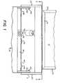
- clamping mechanism 10made in accordance with the present invention.
- the clamping mechanism 10is designed to be incorporated into a reader for reading of a stored image on a stimulable phosphorus sheet/plate that has been exposed to radiation.
- the clamping mechanism 10is designed for use in a raster scanning reader.
- Clamping mechanism 10is designed to receive cassettes 12 and/or pallets containing cassettes 12 such as that disclosed in EPA-92119102.9, entitled “X-ray Cassette with Removable Photographic Film", by Jeffrey C. Robertson, corresponding to EP-A- 0 544 138.
- cassette 12, Fig. 4comprises a shell having upper and lower panels 13,15, Fig. 4.
- a photographic plate or element 17, Fig. 4, of the photostimulable phosphorus typeis disposed therein and is secured to a removable end cap 19, Fig. 4.
- End cap 19includes a latching mechanism (not shown) for releasing end cap 19 and attached photographic plate 17 from the cassette 12.
- photographic plate 17is designed to be removed with end cap 19 from cassette 12.
- the details of construction of the cassetteis described in the Jeffrey C. Robertson application, EPA-92119102.9, previously referred to above.
- clamping mechanism 10comprises a frame 11 having a pair of end plates 20,22 having an upper jaw 24 and moveable lower jaw 26 secured thereto.
- Upper jaw 24is fixed permanently in position and has a planar registration surface 25, Fig. 3, designed to engage with the top panel or surface 13, Fig. 4, of a cassette 12 and lower jaw 26 has a registration planar surface 27, Fig. 3, designed to engage the opposite or lower surface or panel 15, Fig. 4, of cassette 12.
- registration surfaces 25,27are planar.
- positioning of the surface of cassette 12actually occurs by side extrusions 23, Fig. 3, of cassette being held by upper and lower jaws 24,26 which ensures the accurate vertical positioning of cassette 12.
- top panel 13 of cassette 12is slightly bowed outward from cassette 12 such that when cassette 12 is clamped, top panel 13, Fig. 4, is forced downward by upper jaw 24.
- upper jaw 24restrains top panel 13, Fig. 4, so that it is maintained flat and end cap 19 can be reengaged when photographic element 17 is returned to cassette 12. Without top panel 13 being bowed, it would be difficult to return photographic element 17 to cassette 12 as top panel 13 would stay down during clamping.
- Mechanism 10is designed to clamp the forward end 47, Fig. 3 of cassette 12 between registration surfaces 25, 27, Fig. 3, of upper jaw 24 and lower jaw 26. Since side extrusions 23, Fig.
- pneumatic bladder 28is inflated using compressed air and has a substantially elongated configuration having an inlet/outlet port 30, Fig. 2, through which a fluid, such as air, is supplied for inflating of bladder 28 and fluid can be allowed to escape so as to allow deflation of bladder 28.
- a lower mounting plate 32, Fig. 3, secured to side plates 20,22is provided below lower jaw 26 so as to provide a resistant force to bladder 28 when inflated which will cause lower jaw 26 to move toward upper jaw 24 and thereby clamp cassette 12 therebetween. In the clamped position, cassette 12 is lifted off the shelves of the adjacent reader (not shown).
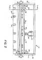
- lower jaw 26is preferably mounted to end plates 20,22 such that, in the non operative position, forward end 33 of lower jaw 26 will be at a position slightly below rear portion 34 of lower jaw 26. In the particular embodiment illustrated, this is provided by providing a pair of cylindrical pins 35 secured to the back end of lower jaw 26 which rides in a substantially vertically elongated slot 36 formed in side plates 20,22.
- Clamping mechanism 10further comprises a stop bar assembly 40 which provides a registration surface against which cassette 12 registers.
- stop bar assembly 40includes a pair of arms 42 having a rear portion 44 which is pivotally mounted to end plates 20,22. Arms 42 each have a general L-shaped configuration, with short legs 43 of arms 42 facing downward. The ends of legs 43 are connected to a stop bar 45 which is designed to extend along the length of the front surface 47 of cassette 12. Stop bar 45 includes a plurality registration surface 46 for mating against the front surface 47 of cassette 12. Arms 42 are movable between an engaged position as illustrated in solid lines in Figures 3 and 4 to a non-engaged position illustrated by phantom lines.
- registration surface 46is provided with a plurality of switches 48 which are designed to engage front surface 47 of cassette 12. In the particular embodiment illustrated, two switches 48 are provided on stop bar 45, however, any desired number may be used.
- switches 48will be depressed, thus providing a signal to microprocessor control unit 65, Fig. 5, which controls the operation of the reader.
- Microprocessor 65is connected to various elements for controlling the operation of the reader as is customarily done in similar prior art devices.
- microprocessor control unit 65does not sense that microswitches 48 have been properly depressed, a message or signal can be provided to the operator that a particular condition has not been met and the reader can be prevented from any further operation until cassette 12 has been properly aligned within the clamping mechanism 10.
- switches 48provide a valuable function in determining whether or not cassette 12 has been properly located to allow extraction of photographic element 17. Switches 48 are positioned so that both large and small cassettes may be properly monitored.
- An optional side sensing switch(not shown) may be provided in one of end plates 20,22 for detecting if one of side extrusions 23 of cassette 12 has been properly registered therewith.
- FIG. 5there is illustrated a schematic diagram of the pneumatic system used to control bladder 28 and pneumatic cylinder 50.
- An appropriate sized air compressor 52is provided for providing fluid pressure to pneumatic cylinder 50 and bladder 28.
- a pressure regulator 54is used to regulate the pressure to bladder 28.
- bladder 28is limited to pressures of approximately 7 psi. However, the fluid pressure may be varied as desired.
- valves 56,58are provided.
- Valve 58in the embodiment shown, controls pressurization of bladder 28 while valve 56 controls the exhaust of fluid pressure therein when deflation is desired.
- Appropriate switches 57 and 59are provided for controlling valves 56,58, respectively.
- Switches 57,59are preferably controlled by microprocessor control unit 65 which determines when bladder 28 should be inflated or deflated. When it is desired to inflate bladder 28, switch 59 is energized so as to open valve 58 to allow fluid pressure to enter bladder 28 and switch 57 is energized so that valve 56 is closed.
- switch 59When the appropriate pressure has been provided to bladder 28, switch 59 is activated to close valve 58, thus maintaining the desired pressure within bladder 28. When it is desired to exhaust the fluid pressure from bladder 28 so as to release cassette 12, switch 59 is activated so that valve 56 allows fluid to escape.
- a pair of valves 60,62are provided for controlling the action of pneumatic cylinder 50.
- Appropriate switches 61,63are provided for controlling valves 60,62, respectively.
- Switches 61,63are also controlled by microprocessor control unit 65 for properly positioning stop bar assembly 40 as required.
- valve 60is activated so as to provide fluid pressure on cylinder 50 for driving drive piston rod 64 to the extended position such that arms 42 rotate about pivot point 49 thus moving registration surface 46 to the engaged position.
- valve 54When it is desired to move stop bar 45 to the non-engaged position, valve 54 is energized which drives piston rod 64 in the opposite direction causing arms 42 to be placed in the retracted position as illustrated by phantom lines in Figures 3 and 4.
- a pair of switches 71,73are provided for sensing an action member 75 attached to one of arms 42.
- switch 71is activated to provide a signal to microprocessor or control unit 65 when stop bar 45 is in the operative position for receiving a cassette and switch 73 provides an appropriate signal to microprocessor control unit 65 when stop bar 45 is in the retracted, non-operative position suitable for allowing the extraction of plate 17 from cassette 12 in the direction, as indicated by arrow 63.
- Clamping mechanism 10is further provided with a mounting plate 80 for mounting the mechanism to the reader.
- mounting plate 80is provided with a plurality of opening/slots 81 for receiving bolts (not shown) for securing the mechanism to the reader.
- mechanism 10may be secured to the reader in any manner desired.
- switches 57,59are energized so as to maintain bladder 28 in the pressurized state. Thereafter, arms 42 of stop bar assembly 40 are moved to the non-engaged position as illustrated by phantom line in Figures 3 and 4. This is accomplished by appropriately activating switches 61,63 so as to place valves 60,62 in the condition causing fluid pressure to be provided to cylinder 50 such that stop bar 45 is moved to the position illustrated by phantom lines in Figures 3 and 4, thus allowing removal of the photographic element in a direction parallel to the cassette as shown by arrow 63.
- Photographic element 17 and associated end cap 19are removed from the end of cassette 12 by an extraction mechanism (not shown) provided in the reader and element 17 is read by the reader as discussed in the patent of Roger S. Brahm and James Lattimore, previously referred to herein.
- Clamping mechanism 10is maintained in the clamped position until the photographic element is returned within cassette 12.
- arms 42are returned to the engaged position and bladder 28 is deflated.
- cassette 12is either removed manually, or by an adjacent automatic loader (not shown). The process is repeated as desired.
- lower jaw 26is moved into the clamping position by use of pneumatic means.
- pneumatic meansother means may be employed.
- a camming mechanism(not shown) could be used to move lower jaw 26 between the clamping and non clamping positions.
- a camcan be rotatably mounted to frame 11 so that it can be rotated, the cam having an outer surface engaging the bottom of moveable jaw 26 so that when the cam is rotated, jaw member 26 will move between the unclamped position shown in Figure 3 to the clamped position shown in Figure 4.
- the present inventionprovides a reliable clamping mechanism for cassettes and/or pallets containing cassettes, allows quick and easy registration of the cassette, is easy and low cost to manufacture and assists in isolating the transmission vibrations through the cassette.
Landscapes
- Physics & Mathematics (AREA)
- General Physics & Mathematics (AREA)
- Radiography Using Non-Light Waves (AREA)
- Clamps And Clips (AREA)
Description
Claims (11)
- Apparatus (10) for clamping a cassette (12) containing a photosensitiveelement (17), comprising:characterized in that;a frame (11);a stop bar (45) movably mounted to the frame (11) for movement between anoperative position in which the stop bar (45) is engaged inregister with the forward end of the cassette (12) and a non operative position, the stop bar (45) havinga registration surface (46) for registering the forward end (47) of the cassette (12);a first jaw member (24) fixed to the frame (11), the first jaw member (24)having a second registration surface (25) for engagement with a first side of thecassette (12);a second movable jaw member (26) movable between a clamping positionand a non clamping position, the second jaw member (26) having a clamping surface(27) for engaging a second side of the cassette (12) opposite the first side of thecassette (12) so as to clamp the cassette (12) between the first and secondjaw members (24,26) when the second jaw member (26) is in the clamping position;means for moving the second movable jaw member (26) between theclamping and non clamping positions,said stop bar (45) is removed from the operative positionwhen said second jaw member (26) is in said clamping position,so that said cassette (12) is supported solely by said jaw members (24,26)for allowing removal of the photosensitive element through the forward end the cassette.
- Apparatus as claimed in claim 1 whereinsaid means for moving the second movable jaw member(26) includes a pneumatic bladder (28) located adjacentthe second movable jaw member (26) which is capable ofbeing inflated to a configuration which causes thesecond jaw member (26) to move from the non clampingposition to a clamping position such that the cassette (12) is clamped between the first and secondjaw members (24,26).
- Apparatus as claimed in claim 1 whereinthe stop bar (45) includes sensing means (48) fordetermining when the cassette (12) has been properlyseated against the registration surface (46).
- Apparatus (10) as claimed in claim 1wherein the stop bar (45) is pivotably mounted to theapparatus (10).
- Apparatus (10) as claimed in claim 1further comprising means (50) for moving the stop bar(45) between the operative and non operative positions.
- Apparatus as claimed in claim 5 whereinsaid means (50) for moving the stop bar (45) comprisespneumatic means.
- Apparatus (10) as claimed in claim 6wherein said pneumatic means comprises a pneumaticcylinder (50).
- Apparatus (10) as claimed in the claims 1and 2 wherein a mounting plate (32) is provided forresisting movement of the bladder (28) so as to causethe second jaw member (26) to move in a directiontoward the first jaw member (24).
- Apparatus (10) as claimed in claim2 wherein said means for moving thesecond movable jaw member (26) comprises;a source of pneumatic pressure (52);first valve means (56,58) fluidly connected to thesource of pneumatic pressure (52) for controllingpressurization and deflation of the bladder (28);second valve means (60,62) fluidly connected to thesource of penumatic pressure (52) for controllingmovement of the stop bar (45) between the operative andnon operative positions.
- Apparatus (10) as claimed in claim 1further comprising means (61,63) for sensing when thestop bar (45) is in the operative position.
- Apparatus (10) as claimed in claim 1wherein the means for moving the second jaw member (26)comprise a cam assembly which moves the second jawmember (26) between the clamping and non-clampingpositions.
Applications Claiming Priority (2)
| Application Number | Priority Date | Filing Date | Title |
|---|---|---|---|
| US981680 | 1992-11-25 | ||
| US07/981,680US5315632A (en) | 1992-11-25 | 1992-11-25 | Cassette clamping mechanism |
Publications (2)
| Publication Number | Publication Date |
|---|---|
| EP0600244A1 EP0600244A1 (en) | 1994-06-08 |
| EP0600244B1true EP0600244B1 (en) | 1998-08-26 |
Family
ID=25528572
Family Applications (1)
| Application Number | Title | Priority Date | Filing Date |
|---|---|---|---|
| EP93117711AExpired - LifetimeEP0600244B1 (en) | 1992-11-25 | 1993-11-02 | Cassette clamping mechanism |
Country Status (4)
| Country | Link |
|---|---|
| US (1) | US5315632A (en) |
| EP (1) | EP0600244B1 (en) |
| JP (1) | JPH06229404A (en) |
| DE (1) | DE69320594T2 (en) |
Families Citing this family (13)
| Publication number | Priority date | Publication date | Assignee | Title |
|---|---|---|---|---|
| US5330309A (en)* | 1992-11-25 | 1994-07-19 | Eastman Kodak Company | Reader having cassette locating and unlatching mechanism |
| US5493128A (en)* | 1994-08-25 | 1996-02-20 | Eastman Kodak Company | Method and apparatus for indexing cassettes |
| DE19523170A1 (en)* | 1995-06-26 | 1997-01-02 | Siemens Ag | Retainer for X-ray film cassette |
| ATE405863T1 (en)* | 2004-09-22 | 2008-09-15 | Agfa Gevaert Healthcare Gmbh | DEVICE FOR READING X-RAY INFORMATION STORED IN A FLUORESCENT STORAGE PLATE |
| US7368747B2 (en)* | 2004-12-17 | 2008-05-06 | Carestream Health, Inc. | Short U-flow multicassette autoloader for a storage phosphor reader |
| US20060195064A1 (en)* | 2005-02-28 | 2006-08-31 | Fresenius Medical Care Holdings, Inc. | Portable apparatus for peritoneal dialysis therapy |
| US7935074B2 (en)* | 2005-02-28 | 2011-05-03 | Fresenius Medical Care Holdings, Inc. | Cassette system for peritoneal dialysis machine |
| US7456419B2 (en) | 2006-08-21 | 2008-11-25 | Carestream Health, Inc. | Radiation imaging cassette |
| US20080058712A1 (en)* | 2006-08-31 | 2008-03-06 | Plahey Kulwinder S | Peritoneal dialysis machine with dual voltage heater circuit and method of operation |
| DE102008013918A1 (en)* | 2008-03-12 | 2009-09-17 | Thoms, Michael, Prof. Dr. | Plate Feeding |
| US8720913B2 (en)* | 2009-08-11 | 2014-05-13 | Fresenius Medical Care Holdings, Inc. | Portable peritoneal dialysis carts and related systems |
| DE102010053973A1 (en) | 2010-12-09 | 2012-06-14 | Fresenius Medical Care Deutschland Gmbh | Medical device with a heater |
| US9186449B2 (en) | 2011-11-01 | 2015-11-17 | Fresenius Medical Care Holdings, Inc. | Dialysis machine support assemblies and related systems and methods |
Citations (4)
| Publication number | Priority date | Publication date | Assignee | Title |
|---|---|---|---|---|
| EP0522316A1 (en)* | 1991-07-11 | 1993-01-13 | Eastman Kodak Company | Autoloader for film cassettes |
| EP0544138A2 (en)* | 1991-11-27 | 1993-06-02 | Eastman Kodak Company | X-ray cassette with removable photographic element |
| US5328019A (en)* | 1992-11-25 | 1994-07-12 | Eastman Kodak Company | Autoloader for cassettes and/or pallet |
| US5330309A (en)* | 1992-11-25 | 1994-07-19 | Eastman Kodak Company | Reader having cassette locating and unlatching mechanism |
Family Cites Families (22)
| Publication number | Priority date | Publication date | Assignee | Title |
|---|---|---|---|---|
| US3150263A (en)* | 1962-12-05 | 1964-09-22 | Kenneth G Catlin | Cassette unloading and reloading machine |
| FR1362137A (en)* | 1963-06-11 | 1964-05-29 | Man Ets De | Clamping device for fixing cassettes on a trolley capable of moving in a serial camera for X-ray equipment |
| US3850316A (en)* | 1974-01-28 | 1974-11-26 | Columbia Machine | Apparatus for loading and unloading vertically stacked racks |
| EP0017273B1 (en)* | 1979-03-30 | 1983-09-14 | Agfa-Gevaert N.V. | Device for positioning radiographic cassettes |
| US4514958A (en)* | 1982-11-24 | 1985-05-07 | E. I. Du Pont De Nemours And Company | Automatic X-ray film cassette unloader and reloader |
| US4538293A (en)* | 1983-02-23 | 1985-08-27 | Cutter James W | X-ray film cassette holder |
| DE3306575A1 (en)* | 1983-02-25 | 1984-08-30 | Winkler & Dünnebier, Maschinenfabrik und Eisengießerei GmbH & Co KG, 5450 Neuwied | COMBINED DE-STACKING-REAR-STACKING DEVICE AS A STACKING-LOADING SYSTEM |
| US4540325A (en)* | 1983-04-18 | 1985-09-10 | Heisler Raymond A | Upstacker apparatus with biased gripping means |
| EP0158838B1 (en)* | 1984-03-16 | 1989-08-09 | Fuji Photo Film Co., Ltd. | Radiation image read-out method and radiation image recording and read-out apparatus |
| JPH0690407B2 (en)* | 1985-07-24 | 1994-11-14 | 富士写真フイルム株式会社 | Radiation image information recording / reading device |
| EP0219821B2 (en)* | 1985-10-17 | 1996-12-18 | Fuji Photo Film Co., Ltd. | Cassette for image information recording carrier, mechanism for removing image information recording carrier from the cassette, and apparatus for reading image information |
| EP0231926B1 (en)* | 1986-02-03 | 1993-12-22 | Fuji Photo Film Co., Ltd. | Radiation image read-out apparatus |
| US4789782A (en)* | 1986-08-15 | 1988-12-06 | Fuji Photo Film Co., Ltd. | Radiation image recording and reproducing system |
| US4845733A (en)* | 1987-05-01 | 1989-07-04 | Liebel-Flarsheim Company | Cassette film transport |
| US4904868A (en)* | 1987-08-19 | 1990-02-27 | Fuji Photo Film Co., Ltd. | Radiation image read-out apparatus and stimulable phosphor sheet composite member for the same |
| DE3731203A1 (en)* | 1987-09-17 | 1989-03-30 | Agfa Gevaert Ag | METHOD FOR HANDLING X-RAY TAKING CASSETTE WITH A PHOSPHOROUS FILM AND READING STATION SUITABLE FOR CARRYING OUT THE METHOD |
| DE3801397A1 (en)* | 1988-01-20 | 1989-08-03 | Grau Gmbh & Co Holdingges | GRIPPERS |
| JPH07101285B2 (en)* | 1988-06-30 | 1995-11-01 | 富士写真フイルム株式会社 | Radiation image information reader |
| FR2646340A1 (en)* | 1989-04-28 | 1990-11-02 | Gen Electric Cgr | ADJUSTABLE CASSETTE HOLDER IN DIMENSION AND POSITION FOR MAMMOGRAPHY |
| US5120178A (en)* | 1989-06-06 | 1992-06-09 | Amada Company | Workpiece loading and unloading method and device for a plate processing machine |
| FR2659221B1 (en)* | 1990-03-08 | 1992-05-22 | General Electric Cgr Sa | DEVICE FOR SETTING UP CASSETTES FOR MAMMOGRAPHERS. |
| US5062130A (en)* | 1990-11-26 | 1991-10-29 | Liebel-Flarsheim Company | X-ray film cassette transport |
- 1992
- 1992-11-25USUS07/981,680patent/US5315632A/ennot_activeExpired - Lifetime
- 1993
- 1993-11-02EPEP93117711Apatent/EP0600244B1/ennot_activeExpired - Lifetime
- 1993-11-02DEDE69320594Tpatent/DE69320594T2/ennot_activeExpired - Fee Related
- 1993-11-24JPJP5293510Apatent/JPH06229404A/enactivePending
Patent Citations (4)
| Publication number | Priority date | Publication date | Assignee | Title |
|---|---|---|---|---|
| EP0522316A1 (en)* | 1991-07-11 | 1993-01-13 | Eastman Kodak Company | Autoloader for film cassettes |
| EP0544138A2 (en)* | 1991-11-27 | 1993-06-02 | Eastman Kodak Company | X-ray cassette with removable photographic element |
| US5328019A (en)* | 1992-11-25 | 1994-07-12 | Eastman Kodak Company | Autoloader for cassettes and/or pallet |
| US5330309A (en)* | 1992-11-25 | 1994-07-19 | Eastman Kodak Company | Reader having cassette locating and unlatching mechanism |
Also Published As
| Publication number | Publication date |
|---|---|
| DE69320594D1 (en) | 1998-10-01 |
| EP0600244A1 (en) | 1994-06-08 |
| JPH06229404A (en) | 1994-08-16 |
| US5315632A (en) | 1994-05-24 |
| DE69320594T2 (en) | 1999-04-01 |
Similar Documents
| Publication | Publication Date | Title |
|---|---|---|
| EP0600244B1 (en) | Cassette clamping mechanism | |
| JP2597799B2 (en) | A device that supplies a plate to the plate cylinder of a printing press | |
| EP0520594B1 (en) | Plate exchange apparatus for printing press | |
| JPH026442Y2 (en) | ||
| US4811547A (en) | Device for loading and unloading X-ray film cassettes | |
| US5207414A (en) | Media handling system for photoplotter and method of use | |
| US5328019A (en) | Autoloader for cassettes and/or pallet | |
| US5044621A (en) | Automatic film-loading device for sheet-film cassettes | |
| US5484139A (en) | System for handling curved form media and cassette therefor | |
| JPH1039028A (en) | Device for handling and automatically positioning filmy sample | |
| US5690327A (en) | Lifting shoe for media handling and related cassette media holder | |
| US4760641A (en) | Apparatus for loading and unloading x-ray film cassettes | |
| JP2594507Y2 (en) | Sample mounting aid | |
| EP0845701B1 (en) | Adjustable chute for X-ray sheet film | |
| JPH08328175A (en) | Scanning device for psl radiography with scanning carriage and belt | |
| US5394220A (en) | Vacuum blanket for pin registration | |
| JP2974849B2 (en) | Automatic plate making method and apparatus | |
| US5481333A (en) | Latchable vacuum blanket frame assembly | |
| JPH0248838Y2 (en) | ||
| JP2705490B2 (en) | X-ray equipment | |
| JPH1039438A (en) | X-ray radiographing device | |
| GB2309028A (en) | Light-tight conveying of sheets | |
| JPH10260504A (en) | Method and device for loading sheetlike photosensitive material | |
| JPH0389243A (en) | Cassette opening and closing mechanism | |
| JPS62141533A (en) | Cassetteless quick photographing device |
Legal Events
| Date | Code | Title | Description |
|---|---|---|---|
| PUAI | Public reference made under article 153(3) epc to a published international application that has entered the european phase | Free format text:ORIGINAL CODE: 0009012 | |
| AK | Designated contracting states | Kind code of ref document:A1 Designated state(s):DE FR GB IT | |
| 17P | Request for examination filed | Effective date:19941020 | |
| 17Q | First examination report despatched | Effective date:19951018 | |
| GRAG | Despatch of communication of intention to grant | Free format text:ORIGINAL CODE: EPIDOS AGRA | |
| GRAG | Despatch of communication of intention to grant | Free format text:ORIGINAL CODE: EPIDOS AGRA | |
| GRAH | Despatch of communication of intention to grant a patent | Free format text:ORIGINAL CODE: EPIDOS IGRA | |
| GRAH | Despatch of communication of intention to grant a patent | Free format text:ORIGINAL CODE: EPIDOS IGRA | |
| GRAA | (expected) grant | Free format text:ORIGINAL CODE: 0009210 | |
| ITF | It: translation for a ep patent filed | ||
| AK | Designated contracting states | Kind code of ref document:B1 Designated state(s):DE FR GB IT | |
| REF | Corresponds to: | Ref document number:69320594 Country of ref document:DE Date of ref document:19981001 | |
| ET | Fr: translation filed | ||
| PLBE | No opposition filed within time limit | Free format text:ORIGINAL CODE: 0009261 | |
| STAA | Information on the status of an ep patent application or granted ep patent | Free format text:STATUS: NO OPPOSITION FILED WITHIN TIME LIMIT | |
| 26N | No opposition filed | ||
| PGFP | Annual fee paid to national office [announced via postgrant information from national office to epo] | Ref country code:GB Payment date:20001004 Year of fee payment:8 | |
| PGFP | Annual fee paid to national office [announced via postgrant information from national office to epo] | Ref country code:FR Payment date:20001107 Year of fee payment:8 | |
| PG25 | Lapsed in a contracting state [announced via postgrant information from national office to epo] | Ref country code:GB Free format text:LAPSE BECAUSE OF NON-PAYMENT OF DUE FEES Effective date:20011102 | |
| REG | Reference to a national code | Ref country code:GB Ref legal event code:IF02 | |
| GBPC | Gb: european patent ceased through non-payment of renewal fee | Effective date:20011102 | |
| PG25 | Lapsed in a contracting state [announced via postgrant information from national office to epo] | Ref country code:FR Free format text:LAPSE BECAUSE OF NON-PAYMENT OF DUE FEES Effective date:20020730 | |
| REG | Reference to a national code | Ref country code:FR Ref legal event code:ST | |
| REG | Reference to a national code | Ref country code:FR Ref legal event code:ST | |
| PGFP | Annual fee paid to national office [announced via postgrant information from national office to epo] | Ref country code:DE Payment date:20031128 Year of fee payment:11 | |
| PG25 | Lapsed in a contracting state [announced via postgrant information from national office to epo] | Ref country code:DE Free format text:LAPSE BECAUSE OF NON-PAYMENT OF DUE FEES Effective date:20050601 | |
| PG25 | Lapsed in a contracting state [announced via postgrant information from national office to epo] | Ref country code:IT Free format text:LAPSE BECAUSE OF NON-PAYMENT OF DUE FEES;WARNING: LAPSES OF ITALIAN PATENTS WITH EFFECTIVE DATE BEFORE 2007 MAY HAVE OCCURRED AT ANY TIME BEFORE 2007. THE CORRECT EFFECTIVE DATE MAY BE DIFFERENT FROM THE ONE RECORDED. Effective date:20051102 |