EP0598631B1 - Oxidation-resistant carbon-carbon composite material with SiC-doped matrix and method of producing said material - Google Patents
Oxidation-resistant carbon-carbon composite material with SiC-doped matrix and method of producing said materialDownload PDFInfo
- Publication number
- EP0598631B1 EP0598631B1EP93400116AEP93400116AEP0598631B1EP 0598631 B1EP0598631 B1EP 0598631B1EP 93400116 AEP93400116 AEP 93400116AEP 93400116 AEP93400116 AEP 93400116AEP 0598631 B1EP0598631 B1EP 0598631B1
- Authority
- EP
- European Patent Office
- Prior art keywords
- carbon
- matrix
- sic
- preform
- powder
- Prior art date
- Legal status (The legal status is an assumption and is not a legal conclusion. Google has not performed a legal analysis and makes no representation as to the accuracy of the status listed.)
- Expired - Lifetime
Links
- 230000003647oxidationEffects0.000titleclaimsdescription64
- 238000007254oxidation reactionMethods0.000titleclaimsdescription64
- 239000000463materialSubstances0.000titleclaimsdescription61
- 239000002131composite materialSubstances0.000titleclaimsdescription60
- 239000011159matrix materialSubstances0.000titleclaimsdescription53
- 238000000034methodMethods0.000titleclaimsdescription34
- CREMABGTGYGIQB-UHFFFAOYSA-Ncarbon carbonChemical compoundC.CCREMABGTGYGIQB-UHFFFAOYSA-N0.000titleclaimsdescription20
- 239000011203carbon fibre reinforced carbonSubstances0.000titleclaimsdescription20
- HBMJWWWQQXIZIP-UHFFFAOYSA-Nsilicon carbideChemical compound[Si+]#[C-]HBMJWWWQQXIZIP-UHFFFAOYSA-N0.000claimsdescription104
- 229910010271silicon carbideInorganic materials0.000claimsdescription101
- 239000000843powderSubstances0.000claimsdescription63
- OKTJSMMVPCPJKN-UHFFFAOYSA-NCarbonChemical compound[C]OKTJSMMVPCPJKN-UHFFFAOYSA-N0.000claimsdescription53
- 229910052799carbonInorganic materials0.000claimsdescription51
- 229920005989resinPolymers0.000claimsdescription51
- 239000011347resinSubstances0.000claimsdescription51
- 239000000835fiberSubstances0.000claimsdescription50
- 238000000576coating methodMethods0.000claimsdescription24
- 239000011248coating agentSubstances0.000claimsdescription22
- 239000000203mixtureSubstances0.000claimsdescription21
- 230000008569processEffects0.000claimsdescription20
- 230000004888barrier functionEffects0.000claimsdescription19
- 238000004519manufacturing processMethods0.000claimsdescription19
- 238000005470impregnationMethods0.000claimsdescription15
- 238000009792diffusion processMethods0.000claimsdescription13
- 238000000197pyrolysisMethods0.000claimsdescription13
- 239000007833carbon precursorSubstances0.000claimsdescription12
- 230000001590oxidative effectEffects0.000claimsdescription11
- VYPSYNLAJGMNEJ-UHFFFAOYSA-NSilicium dioxideChemical compoundO=[Si]=OVYPSYNLAJGMNEJ-UHFFFAOYSA-N0.000claimsdescription9
- 238000000280densificationMethods0.000claimsdescription7
- 238000006243chemical reactionMethods0.000claimsdescription6
- 229910003465moissaniteInorganic materials0.000claimsdescription5
- 230000000379polymerizing effectEffects0.000claimsdescription4
- 239000000377silicon dioxideSubstances0.000claimsdescription4
- 239000002904solventSubstances0.000claimsdescription4
- 238000005229chemical vapour depositionMethods0.000claimsdescription2
- 238000005524ceramic coatingMethods0.000claims3
- 229910052681coesiteInorganic materials0.000claims2
- 229910052906cristobaliteInorganic materials0.000claims2
- 229910052682stishoviteInorganic materials0.000claims2
- 229910052905tridymiteInorganic materials0.000claims2
- 238000001033granulometryMethods0.000claims1
- 239000011148porous materialSubstances0.000claims1
- 239000010410layerSubstances0.000description45
- 229910004298SiO 2Inorganic materials0.000description14
- 229910052760oxygenInorganic materials0.000description13
- 229920000049Carbon (fiber)Polymers0.000description12
- QVGXLLKOCUKJST-UHFFFAOYSA-Natomic oxygenChemical compound[O]QVGXLLKOCUKJST-UHFFFAOYSA-N0.000description12
- 239000004917carbon fiberSubstances0.000description12
- 239000007789gasSubstances0.000description12
- 239000001301oxygenSubstances0.000description12
- 239000004744fabricSubstances0.000description11
- 239000002245particleSubstances0.000description11
- IUHFWCGCSVTMPG-UHFFFAOYSA-N[C].[C]Chemical class[C].[C]IUHFWCGCSVTMPG-UHFFFAOYSA-N0.000description6
- 238000012360testing methodMethods0.000description6
- 230000015572biosynthetic processEffects0.000description5
- 229920001568phenolic resinPolymers0.000description5
- 238000006116polymerization reactionMethods0.000description5
- 229910018072Al 2 O 3Inorganic materials0.000description4
- 238000002679ablationMethods0.000description4
- 230000006399behaviorEffects0.000description4
- 230000008901benefitEffects0.000description4
- 238000000151depositionMethods0.000description4
- 229920002239polyacrylonitrilePolymers0.000description4
- LIVNPJMFVYWSIS-UHFFFAOYSA-Nsilicon monoxideInorganic materials[Si-]#[O+]LIVNPJMFVYWSIS-UHFFFAOYSA-N0.000description4
- LFQSCWFLJHTTHZ-UHFFFAOYSA-NEthanolChemical compoundCCOLFQSCWFLJHTTHZ-UHFFFAOYSA-N0.000description3
- 230000003064anti-oxidating effectEffects0.000description3
- 238000005553drillingMethods0.000description3
- 239000011521glassSubstances0.000description3
- 229910002804graphiteInorganic materials0.000description3
- 239000010439graphiteSubstances0.000description3
- VNWKTOKETHGBQD-UHFFFAOYSA-NmethaneChemical compoundCVNWKTOKETHGBQD-UHFFFAOYSA-N0.000description3
- 239000011241protective layerSubstances0.000description3
- 239000011819refractory materialSubstances0.000description3
- 239000000758substrateSubstances0.000description3
- 230000008961swellingEffects0.000description3
- 210000001519tissueAnatomy0.000description3
- 230000009466transformationEffects0.000description3
- KXGFMDJXCMQABM-UHFFFAOYSA-N2-methoxy-6-methylphenolChemical compound[CH]OC1=CC=CC([CH])=C1OKXGFMDJXCMQABM-UHFFFAOYSA-N0.000description2
- XKRFYHLGVUSROY-UHFFFAOYSA-NArgonChemical compound[Ar]XKRFYHLGVUSROY-UHFFFAOYSA-N0.000description2
- IJGRMHOSHXDMSA-UHFFFAOYSA-NAtomic nitrogenChemical compoundN#NIJGRMHOSHXDMSA-UHFFFAOYSA-N0.000description2
- 229910052582BNInorganic materials0.000description2
- PZNSFCLAULLKQX-UHFFFAOYSA-NBoron nitrideChemical compoundN#BPZNSFCLAULLKQX-UHFFFAOYSA-N0.000description2
- YLQBMQCUIZJEEH-UHFFFAOYSA-NFuranChemical compoundC=1C=COC=1YLQBMQCUIZJEEH-UHFFFAOYSA-N0.000description2
- KFZMGEQAYNKOFK-UHFFFAOYSA-NIsopropanolChemical compoundCC(C)OKFZMGEQAYNKOFK-UHFFFAOYSA-N0.000description2
- 229910018557Si OInorganic materials0.000description2
- 239000000654additiveSubstances0.000description2
- PNEYBMLMFCGWSK-UHFFFAOYSA-Naluminium oxideInorganic materials[O-2].[O-2].[O-2].[Al+3].[Al+3]PNEYBMLMFCGWSK-UHFFFAOYSA-N0.000description2
- 238000005520cutting processMethods0.000description2
- 230000008021depositionEffects0.000description2
- 239000012530fluidSubstances0.000description2
- SLGWESQGEUXWJQ-UHFFFAOYSA-Nformaldehyde;phenolChemical compoundO=C.OC1=CC=CC=C1SLGWESQGEUXWJQ-UHFFFAOYSA-N0.000description2
- 238000010438heat treatmentMethods0.000description2
- 238000005259measurementMethods0.000description2
- 230000007935neutral effectEffects0.000description2
- 238000005457optimizationMethods0.000description2
- 239000002243precursorSubstances0.000description2
- 238000003825pressingMethods0.000description2
- 230000001681protective effectEffects0.000description2
- 230000007704transitionEffects0.000description2
- 230000002747voluntary effectEffects0.000description2
- 229910017083AlNInorganic materials0.000description1
- NLXLAEXVIDQMFP-UHFFFAOYSA-NAmmonium chlorideSubstances[NH4+].[Cl-]NLXLAEXVIDQMFP-UHFFFAOYSA-N0.000description1
- VHUUQVKOLVNVRT-UHFFFAOYSA-NAmmonium hydroxideChemical compound[NH4+].[OH-]VHUUQVKOLVNVRT-UHFFFAOYSA-N0.000description1
- ZOXJGFHDIHLPTG-UHFFFAOYSA-NBoronChemical compound[B]ZOXJGFHDIHLPTG-UHFFFAOYSA-N0.000description1
- 241001415961GaviidaeSpecies0.000description1
- 229910021193La 2 O 3Inorganic materials0.000description1
- 229910052581Si3N4Inorganic materials0.000description1
- XUIMIQQOPSSXEZ-UHFFFAOYSA-NSiliconChemical compound[Si]XUIMIQQOPSSXEZ-UHFFFAOYSA-N0.000description1
- QCWXUUIWCKQGHC-UHFFFAOYSA-NZirconiumChemical compound[Zr]QCWXUUIWCKQGHC-UHFFFAOYSA-N0.000description1
- 230000009471actionEffects0.000description1
- 238000005054agglomerationMethods0.000description1
- 230000002776aggregationEffects0.000description1
- 230000016571aggressive behaviorEffects0.000description1
- QGZKDVFQNNGYKY-UHFFFAOYSA-NammoniaNatural productsNQGZKDVFQNNGYKY-UHFFFAOYSA-N0.000description1
- 235000011114ammonium hydroxideNutrition0.000description1
- 238000004458analytical methodMethods0.000description1
- 229910052786argonInorganic materials0.000description1
- 229910052796boronInorganic materials0.000description1
- 229910052810boron oxideInorganic materials0.000description1
- 239000005388borosilicate glassSubstances0.000description1
- 244000309464bullSpecies0.000description1
- JLQUFIHWVLZVTJ-UHFFFAOYSA-NcarbosulfanChemical compoundCCCCN(CCCC)SN(C)C(=O)OC1=CC=CC2=C1OC(C)(C)C2JLQUFIHWVLZVTJ-UHFFFAOYSA-N0.000description1
- 239000000919ceramicSubstances0.000description1
- 238000005234chemical depositionMethods0.000description1
- 239000000571cokeSubstances0.000description1
- 230000000295complement effectEffects0.000description1
- 150000001875compoundsChemical class0.000description1
- 239000000470constituentSubstances0.000description1
- 229910021419crystalline siliconInorganic materials0.000description1
- 230000007423decreaseEffects0.000description1
- 238000005137deposition processMethods0.000description1
- 230000006866deteriorationEffects0.000description1
- JKWMSGQKBLHBQQ-UHFFFAOYSA-Ndiboron trioxideChemical compoundO=BOB=OJKWMSGQKBLHBQQ-UHFFFAOYSA-N0.000description1
- 239000006185dispersionSubstances0.000description1
- 230000000694effectsEffects0.000description1
- 238000005516engineering processMethods0.000description1
- QFXZANXYUCUTQH-UHFFFAOYSA-NethynolChemical groupOC#CQFXZANXYUCUTQH-UHFFFAOYSA-N0.000description1
- 239000000945fillerSubstances0.000description1
- 230000004907fluxEffects0.000description1
- 125000000524functional groupChemical group0.000description1
- 230000004927fusionEffects0.000description1
- 230000035876healingEffects0.000description1
- 238000000265homogenisationMethods0.000description1
- 230000002706hydrostatic effectEffects0.000description1
- 238000007654immersionMethods0.000description1
- 238000011065in-situ storageMethods0.000description1
- 230000008595infiltrationEffects0.000description1
- 238000001764infiltrationMethods0.000description1
- 239000007788liquidSubstances0.000description1
- 238000003754machiningMethods0.000description1
- 229910052751metalInorganic materials0.000description1
- 239000002184metalSubstances0.000description1
- 150000001247metal acetylidesChemical class0.000description1
- 238000002156mixingMethods0.000description1
- 229910052757nitrogenInorganic materials0.000description1
- 229920000368omega-hydroxypoly(furan-2,5-diylmethylene) polymerPolymers0.000description1
- 125000002524organometallic groupChemical group0.000description1
- 239000007800oxidant agentSubstances0.000description1
- ISWSIDIOOBJBQZ-UHFFFAOYSA-Nphenol groupChemical groupC1(=CC=CC=C1)OISWSIDIOOBJBQZ-UHFFFAOYSA-N0.000description1
- 239000005011phenolic resinSubstances0.000description1
- 229920002480polybenzimidazolePolymers0.000description1
- 239000011160polymer matrix compositeSubstances0.000description1
- 229920013657polymer matrix compositePolymers0.000description1
- 238000012545processingMethods0.000description1
- 239000002296pyrolytic carbonSubstances0.000description1
- 238000011084recoveryMethods0.000description1
- 230000009467reductionEffects0.000description1
- 230000001105regulatory effectEffects0.000description1
- 239000012783reinforcing fiberSubstances0.000description1
- 229920003987resolePolymers0.000description1
- 238000012552reviewMethods0.000description1
- 239000003566sealing materialSubstances0.000description1
- 229910052710siliconInorganic materials0.000description1
- 239000010703siliconSubstances0.000description1
- HQVNEWCFYHHQES-UHFFFAOYSA-Nsilicon nitrideChemical compoundN12[Si]34N5[Si]62N3[Si]51N64HQVNEWCFYHHQES-UHFFFAOYSA-N0.000description1
- 229910052814silicon oxideInorganic materials0.000description1
- 239000007787solidSubstances0.000description1
- 238000010025steamingMethods0.000description1
- 239000000126substanceSubstances0.000description1
- 238000002604ultrasonographyMethods0.000description1
- 239000012808vapor phaseSubstances0.000description1
- 238000009941weavingMethods0.000description1
- 238000005303weighingMethods0.000description1
- 230000004580weight lossEffects0.000description1
- 229910052726zirconiumInorganic materials0.000description1
Images

Classifications
- C—CHEMISTRY; METALLURGY
- C04—CEMENTS; CONCRETE; ARTIFICIAL STONE; CERAMICS; REFRACTORIES
- C04B—LIME, MAGNESIA; SLAG; CEMENTS; COMPOSITIONS THEREOF, e.g. MORTARS, CONCRETE OR LIKE BUILDING MATERIALS; ARTIFICIAL STONE; CERAMICS; REFRACTORIES; TREATMENT OF NATURAL STONE
- C04B38/00—Porous mortars, concrete, artificial stone or ceramic ware; Preparation thereof
- C04B38/0022—Porous mortars, concrete, artificial stone or ceramic ware; Preparation thereof obtained by a chemical conversion or reaction other than those relating to the setting or hardening of cement-like material or to the formation of a sol or a gel, e.g. by carbonising or pyrolysing preformed cellular materials based on polymers, organo-metallic or organo-silicon precursors
- C04B38/0032—Porous mortars, concrete, artificial stone or ceramic ware; Preparation thereof obtained by a chemical conversion or reaction other than those relating to the setting or hardening of cement-like material or to the formation of a sol or a gel, e.g. by carbonising or pyrolysing preformed cellular materials based on polymers, organo-metallic or organo-silicon precursors one of the precursor materials being a monolithic element having approximately the same dimensions as the final article, e.g. a paper sheet which after carbonisation will react with silicon to form a porous silicon carbide porous body
- C—CHEMISTRY; METALLURGY
- C04—CEMENTS; CONCRETE; ARTIFICIAL STONE; CERAMICS; REFRACTORIES
- C04B—LIME, MAGNESIA; SLAG; CEMENTS; COMPOSITIONS THEREOF, e.g. MORTARS, CONCRETE OR LIKE BUILDING MATERIALS; ARTIFICIAL STONE; CERAMICS; REFRACTORIES; TREATMENT OF NATURAL STONE
- C04B35/00—Shaped ceramic products characterised by their composition; Ceramics compositions; Processing powders of inorganic compounds preparatory to the manufacturing of ceramic products
- C04B35/71—Ceramic products containing macroscopic reinforcing agents
- C04B35/78—Ceramic products containing macroscopic reinforcing agents containing non-metallic materials
- C04B35/80—Fibres, filaments, whiskers, platelets, or the like
- C04B35/83—Carbon fibres in a carbon matrix
- C—CHEMISTRY; METALLURGY
- C04—CEMENTS; CONCRETE; ARTIFICIAL STONE; CERAMICS; REFRACTORIES
- C04B—LIME, MAGNESIA; SLAG; CEMENTS; COMPOSITIONS THEREOF, e.g. MORTARS, CONCRETE OR LIKE BUILDING MATERIALS; ARTIFICIAL STONE; CERAMICS; REFRACTORIES; TREATMENT OF NATURAL STONE
- C04B41/00—After-treatment of mortars, concrete, artificial stone or ceramics; Treatment of natural stone
- C04B41/009—After-treatment of mortars, concrete, artificial stone or ceramics; Treatment of natural stone characterised by the material treated
- C—CHEMISTRY; METALLURGY
- C04—CEMENTS; CONCRETE; ARTIFICIAL STONE; CERAMICS; REFRACTORIES
- C04B—LIME, MAGNESIA; SLAG; CEMENTS; COMPOSITIONS THEREOF, e.g. MORTARS, CONCRETE OR LIKE BUILDING MATERIALS; ARTIFICIAL STONE; CERAMICS; REFRACTORIES; TREATMENT OF NATURAL STONE
- C04B41/00—After-treatment of mortars, concrete, artificial stone or ceramics; Treatment of natural stone
- C04B41/45—Coating or impregnating, e.g. injection in masonry, partial coating of green or fired ceramics, organic coating compositions for adhering together two concrete elements
- C04B41/50—Coating or impregnating, e.g. injection in masonry, partial coating of green or fired ceramics, organic coating compositions for adhering together two concrete elements with inorganic materials
- C04B41/5025—Coating or impregnating, e.g. injection in masonry, partial coating of green or fired ceramics, organic coating compositions for adhering together two concrete elements with inorganic materials with ceramic materials
- C—CHEMISTRY; METALLURGY
- C04—CEMENTS; CONCRETE; ARTIFICIAL STONE; CERAMICS; REFRACTORIES
- C04B—LIME, MAGNESIA; SLAG; CEMENTS; COMPOSITIONS THEREOF, e.g. MORTARS, CONCRETE OR LIKE BUILDING MATERIALS; ARTIFICIAL STONE; CERAMICS; REFRACTORIES; TREATMENT OF NATURAL STONE
- C04B41/00—After-treatment of mortars, concrete, artificial stone or ceramics; Treatment of natural stone
- C04B41/80—After-treatment of mortars, concrete, artificial stone or ceramics; Treatment of natural stone of only ceramics
- C04B41/81—Coating or impregnation
- C04B41/85—Coating or impregnation with inorganic materials
- C04B41/87—Ceramics
- C—CHEMISTRY; METALLURGY
- C04—CEMENTS; CONCRETE; ARTIFICIAL STONE; CERAMICS; REFRACTORIES
- C04B—LIME, MAGNESIA; SLAG; CEMENTS; COMPOSITIONS THEREOF, e.g. MORTARS, CONCRETE OR LIKE BUILDING MATERIALS; ARTIFICIAL STONE; CERAMICS; REFRACTORIES; TREATMENT OF NATURAL STONE
- C04B2235/00—Aspects relating to ceramic starting mixtures or sintered ceramic products
- C04B2235/02—Composition of constituents of the starting material or of secondary phases of the final product
- C04B2235/30—Constituents and secondary phases not being of a fibrous nature
- C04B2235/38—Non-oxide ceramic constituents or additives
- C04B2235/3817—Carbides
- C04B2235/3826—Silicon carbides
- C—CHEMISTRY; METALLURGY
- C04—CEMENTS; CONCRETE; ARTIFICIAL STONE; CERAMICS; REFRACTORIES
- C04B—LIME, MAGNESIA; SLAG; CEMENTS; COMPOSITIONS THEREOF, e.g. MORTARS, CONCRETE OR LIKE BUILDING MATERIALS; ARTIFICIAL STONE; CERAMICS; REFRACTORIES; TREATMENT OF NATURAL STONE
- C04B2235/00—Aspects relating to ceramic starting mixtures or sintered ceramic products
- C04B2235/70—Aspects relating to sintered or melt-casted ceramic products
- C04B2235/80—Phases present in the sintered or melt-cast ceramic products other than the main phase
Definitions
- the present inventionrelates to a part structural mechanics of composite material of the type carbon-carbon made stainless at high temperature and in particular up to 1700 ° C without coating external anti-oxidation protection as well as its manufacturing process.
- Structural parts made of composite material carbon-carbon typehave thermal resistance high performance and are more particularly intended to be used for the realization of space vehicles (shuttles or aircraft) in front resist the heating caused by friction air when they re-enter at high speed into the atmosphere.
- spacecraftare in particular those whose re-entry missions involve in singular points more stressed than others such as the nose, the ailerons or leading edges, exposures to severe conditions and in particular to temperatures up to '' at 1700 ° C under air pressures of up to 10 5 Pa or cause the exposure of certain parts to variable temperatures (from 1000 ° C to 1700 ° C).
- the inventionalso applies in other industrial sectors requiring use pieces of refractory material keeping good mechanical properties above 1100 ° C in the middle corrosive. This is particularly the case for improved efficiency turbine working at high temperature (from 1300 ° C to 1400 ° C) and some industrial heat recovery units.
- Mechanical parts made of composite materials to which the invention appliesconsist of carbon reinforcing fibers embedded in a matrix of carbon.
- the fiberscan be short or long, woven or wound, braided or braided. They can be arranged in one, two, three, four or more directions.
- protective layers of silicon carbide surrounding each carbon fiberwere considered as described in documents EP-A-0 121 797 and US-A-4 976 899.
- the carbon-carbon materialis protected by swelling during the formation of B 2 O 3 and especially by the formation of a layer of B 2 O 3 which opposes the arrival of oxygen.
- B 2 O 3including in mixture with other oxides such as SiO 2 or ZrO 2 , volatilizes above 1000 ° C. Thus, the protection it can provide disappears above this temperature.
- Boron oxidecan result from oxidation boron nitride or a metal boride. Employment boron nitride and metallic boride is taught by document US-A-4 119 189.
- Document FR-A-2 104 563describes the production of a composite pyrolytic material comprising a matrix of pyrolytic graphite and nested silicon carbide. This matrix is obtained by chemical vapor deposition (DCPV) of SiC and graphite in a substrate porous. The amount of SiC in the matrix can represent up to 95% by volume. This quantity very high SiC results in embrittlement of the material composite, SiC being much less resistant mechanically than carbon.
- DCPVchemical vapor deposition
- This method of introducing SiC into the carbon matrix, in the absence of an outer layer of SiC on the composite material,does not ensure effective protection of the material against oxidation.
- the subject of the inventionis a mechanical part structural in a new carbon-carbon composite material, protected against oxidation and its manufacturing process to remedy the various disadvantages mentioned above.
- This composite material parthas a high resistance mechanical and oxidation resistance up to temperature of 1700 ° C, without the use of a layer external protection, especially in the presence of a flow oxidizing gas.
- Italso has a reduction by at least two of its oxidation rate between 1000 ° C and 1700 ° C, without external coating, in the presence of a mass flow of oxygen greater than 0.005 Kg / m 2 / s.
- this mechanical part made of material compositein particular due to its simplicity of manufacturing, may have a diameter greater than meter and can for example constitute the nose of a shuttle bus.
- the physical principle implemented in the inventionis totally different from those used so far and described above; he is particularly well suited to oxidation conditions which are of the same type as those of a return to school oxidizing atmosphere.
- the oxygen flow and the temperatures involvedare very high and the oxidation rates of a non-carbon-carbon material protected can reach 1mm per minute during the back to school, on average.
- the principle of the inventionis to create a gas diffusion barrier on the surface of the material.
- a gas diffusion barrieris much easier to achieve than a waterproof layer gas, as sought so far, because precisely there is no need for a perfect seal; just prevent the aerodynamic flow from reaching at the oxidation front. In this case too, the fiber protection is simultaneous to that of the matrix and no specific action on this point has need to be performed.
- the diffusion barrier gasis made, the oxidation kinetics of the composite material part are controlled by the diffusion of oxygen in the gaseous state; the laws of kinetics are parabolic laws.
- this diffusion barrieris formed by powdered SiC located in particular in the large porosities of the composite material. In the presence of oxygen, this SiC oxidizes to SiO 2 and binds the different particles together to create this barrier.
- the composite material part of the inventionis therefore much simpler than those of the prior art and its implementation is much less expensive.
- the inventionhas for object a structural part in composite material, protected against oxidation, comprising a preform fibrous consisting only of carbon fibers embedded in a carbon matrix whose porosities contain ultrafine carbide powder crystalline silicon acting as a barrier to gas diffusion, the quantity of powder representing from 5 to 30% by weight of the preform-matrix-powder assembly.
- SICPreferably, from 5 to 20% by weight is used of SIC compared to the preform-matrix-powder assembly.
- SiCan amount of SiC> 30% by weight, the mechanical properties of the part are degraded.
- the carbon-carbon part of the inventionhas oxidation resistance performance, without a layer of external protection (P.A.O.) and without a layer of fiber protection, within a temperature range up to 1700 ° C.
- the armed and doped matrixhas to it alone has a high capacity for resistance to oxidation and ensures the protection of the part.
- the part of the inventionis intended more specially to constitute structural elements such as the nose, fins or leading edges of a space vehicle.
- the volume ratio of fiberswhich represents the volume ratio occupied by fibers / total material volume, is ⁇ 40% and in chosen practice from 45 to 60%.
- the fibers usedare preferably continuous and oriented in more than two directions.
- the SiC powder usedmust have grains with an average diameter of less than 1/10 of fiber diameter. So for carbon fibers having fiber diameters from 5 to 10 ⁇ m, the powder must have a submicron particle size.
- powders of particle sizeranging from 0.1 ⁇ m to 0.6 ⁇ m.
- a grain size too finethere is no agglomeration of grains and with too large a grain size the grains cannot be accommodated in the porosities of the matrix.
- Such a particle sizeis sufficient because the powder does not necessarily need to go within fibers, it just has to go into the porosities between fibers (cracks or pockets - bytes in the case of materials woven using the 3D technique -). We means pockets (or bytes) voids in the substrate present between the fibers before its densification.
- the carbon matrixresults at least in part from the pyrolysis of a resin polymerized carbon precursor.
- the composite material part described previouslywas developed with a view to the use of a space vehicle carrying out only one single mission. For multi-mission use, it is better to carry out external protection against oxidation covering the entire outer surface of the room.
- This external protection or external PAOconsists of one or more external layers of ceramics.
- This outer layercan be made of SiC, Si 3 N 4 or a refractory oxide such as ThO 2 , ZrO 2 , HfO 2 , La 2 O 3 , Y 2 O 3 , and Al 2 O 3 .
- an intermediate layer of reaction barrierIn order to avoid a chemical reaction between the carbide of the outer layer of SiC and the layer oxide, an intermediate layer of reaction barrier.
- an intermediate layerwe can use one of those described in the document FR-A-2 635 773.
- the intermediate layer of reaction barrieris in AlN or HfN.
- silica and / or a borosilicate glassSiO 2 -B 2 O 3 ) as described in document US-A-4,863,773.
- the oxide layer constituting itgenerally constitutes the outermost layer.
- the material underlying containing the SiC powderplays the role security element in case of deterioration accidental P.A.O. (e.g. hail, meteorites for a space vehicle). In this case re-entry into the atmosphere of the spacecraft may do without problem.
- the SiC powder introduced into the matrixthen plays the role of a second level of protection against oxidation of the part, the first level of protection being provided by the P.A.O.
- the inventionalso relates to a method of manufacture of a composite material part such as previously described.
- the impregnation of carbon fibers by the resin carbon precursor and SiC powdercan be performed before or after the preform is shaped fibrous.
- a first methodconsists in: (a) make a fiber preform of the part, consisting only carbon fibers, (b) impregnate this preform by an impregnation bath containing a carbon precursor resin and ultrafine powder crystalline SiC, dout the average grain diameter is less than 1/10 of the fiber diameter the amount of SiC powder in the bath being such that this powder represents from 5 to 30% by weight of the densified preform, (c) polymerize the resin of the loaded preform then pyrolyze it to transform it into carbon and thus densify the loaded preform.
- a second methodconsists in: (A) impregnating at least one carbon fiber per bath impregnation containing a precursor resin carbon and ultrafine powder of crystalline SiC, dout the average grain diameter is less than 1/10 of the fiber diameter the amount of SiC powder in the bath being such that this powder represents from 5 to 30% by weight of the densified preform, (B) make a fibrous preform of the part, made up only of this fiber of impregnated carbon, (C) polymerize the resin of the loaded preform then pyrolyze it to transform it carbon and thus densify the loaded preform.
- the process of the inventioncan therefore be implemented implemented with the same means as those industrially used for the manufacture of parts unprotected carbon-carbon. So we can do better manage the optimization of the mechanical properties of the mechanical part that processes using resins modified.
- the resins used in the inventionare therefore chosen on other criteria than that of the resistance to oxidation of the part. They are for example phenol-formaldehyde, furan, polyfurfuryl alcohol, polydiethylmethylbenzene, polybenzimidazol, etc.
- resinswhich, when pyrolysis, introduce SiC or BN into the matrix.
- the impregnation bathcontains per 100 parts by weight of resin, from 10 to 100 parts by weight of SiC powder and from 0 to 10 parts by weight of solvent.
- the principle put at stake in the inventionis protection against oxidation using a diffusion barrier carbonated.
- the subject of the inventionis also a method of protection against oxidation with respect to an oxidizing gas flow up to 1700 ° C. of a composite material with carbon fibers linked together by a matrix of carbon, consisting in forming in the matrix a gas diffusion barrier into porous SiO 2 by transformation of an ultrafine powder of crystalline SiC, placed in the porosities of the matrix at a rate of 5 to 30% by weight of the fiber assembly matrix-powder.
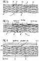
- the composite material part represented in Figure 1is a flat plate 1 consisting of a fibrous preform formed only of continuous fibers of untreated carbon 4 woven using the technique 2.5D described in document FR-A-2 610 951; the fibers 4 are actually strands made of several hundred carbon fibrils.
- These woven strands 4are embedded in a carbon matrix 6 resulting from the pyrolysis of a polymerized resin, carbon precursor.
- fibers 4come from polyacrylonitrile pyrolysis (PAN). They have a diameter of around 7 ⁇ m.
- the resins usedare in particular of phenolformaldehyde resins of the type Resol.
- ultrafine powder 10 of SiC crystallineIn the cracks 7 of the carbon matrix 6 and in the bytes (or pockets) 8 between the strands woven 4, is housed with ultrafine powder 10 of SiC crystalline.
- This powderhas a smaller particle size at 1/10 the diameter of the fibers 4.
- the particle sizeis ⁇ 0.7 ⁇ m and is typically from 0.1 ⁇ m to 0.6 ⁇ m.
- the powderrepresents 5 to 30% by weight of the plate and typically 15% by weight.
- FIG. 1athe piece of material composite of the invention is shown before being subjected to a flow of oxygen and in FIG. 1b, we have represented this same piece when subjected to an oxygen flow 12.
- the SiC powder 10 contained in the cracks 7 and the bytes 8is transformed into porous SiO 2 while remaining in the same place and the carbon of the SiC is consumed.
- the oxidized SiC remaining in its placea layer of silicon oxide 14 is formed which represents the negatives of the porosities 7 and 8 of the initial part.
- This layer 14 of porous SiO 2 oxideacts as a gas diffusion barrier and thereby reduces the carbon consumption of the matrix and of the fibers.
- untreated fiberscorresponds to an optimization of mechanical properties of the composite material part as well as a lowering of its manufacturing cost.
- This exampleis described with reference to the Figure 2, illustrating the different stages of manufacturing of a structural part in accordance with the invention.
- This piececomes in the form a flat plate whose fibrous preform is made with continuous carbon fibers not processed, woven using the 3D technique described by example in document FR-A-2 612 950. These fibers come from the pyrolysis of PAN.
- the second stage of the processconsists, as shown schematically by block 22, to impregnate the preform fibrous mixture of carbon precursor resin and crystalline SiC powder.
- This mixturecontains particular 100 parts by weight of resin phenolformaldehyde, from 10 to 100 parts by weight of SiC powder and 0 to 100 parts by weight of solvent such as lower alcohol. Mixing is done carefully so as to be homogeneous and well scattered. For this purpose, a disperser is used and especially an ultrasonic disperser.
- the mixturecontains 100 parts by weight of formophenolic resin, 50 parts by weight of SiC powder, 50 parts by weight of alcohol ; the SiC powder is VF25 from Lonza from particle size between 0.1 and 0.6 ⁇ m.
- the impregnationis carried out under vacuum until the resin-SiC mixture no longer forms a bubble.
- the pressure prevailing in the vacuum enclosureis 10 3 Pa. Furthermore, this is brought to a temperature of 70 ° C.
- the fiber preformis impregnated with the SiC resin-powder mixture for 24 hours.
- the next step in the processconsists in polymerizing the resin under neutral gas (nitrogen, argon) under a pressure of 10 5 and at a temperature of 200 ° C.
- neutral gasnitrogen, argon
- the polymerized resinis then transformed into coke.
- This transformationconsists of pyrolysis at 850 ° C for 3 hours under neutral gas at a pressure of 10 5 Pa; this step is symbolized by block 26 in FIG. 2.
- densificationis carried out complementary, symbolized by block 28, consisting in one or more impregnation cycles, polymerization and pyrolysis with resin phenolic alone.
- the number of cycles with the resin onlyis generally 1 to 3.
- the mechanical part obtainedis ready for use after having undergone any machining.
- the inventorshave made of composite material parts, the fibers were woven using the 2D technique.
- a fabricas indicated by the block 20a, consisting of strands of continuous fibers of untreated carbon, arranged parallel to each other to form sheets; the strands of two tablecloths consecutive are perpendicular to each other.
- a mixture of pheno ⁇ formaldehyde resin, carbon precursor, and crystalline SiC powder with a particle size of 0.1 ⁇ m to 0.6 ⁇ mcontains 100 parts by weight of resin and 5 to 100 parts by weight of SiC.
- the resulting impregnated fabriccan be stored in a cold room, at a temperature below -18 ° C, and wait until used.
- the steps of cutting, stacking and pressing pieces of fabricmake up step 25 of production of the resin-filled fiber preform and SiC.
- a fiber preformwith a resin-SiC mixture containing very little resin.
- a slipconsisting of an aqueous ammonia solution at pH 12, at 200g / l of SiC powder (reference VF25 from Lonza) and containing 10% by weight of phenolic resin agrees.
- Example 1The impregnation is then carried out as in Example 1, under vacuum until the mixture no longer forms bubbles; the pressure is then 10 3 Pa.
- the polymerization of the resin and its pyrolysisare also carried out according to Example 1.
- step 28it is then possible to finish the densification (step 28) by impregnating the already densified part with pitch or by carbon deposition by chemical deposition in vapor phase (DCPV) instead of performing cycles resin impregnation alone, polymerization and pyrolysis of this resin described in Example 1, of so as to get a denser carbon matrix and more conductive of heat.
- DCPVchemical deposition in vapor phase
- the composite material parts described previouslydid not include an external P.A.O., the parts oxidation protection were ensured only by the SiC powder introduced into the matrix.
- This partdiffers from that of FIG. 1 only by the presence of the PAO
- the lattercomprises an external layer 30 of SiC on its entire external surface, 300 to 500 ⁇ m thick, obtained by siliciding the carbon of the matrix 6 and fibers 4, on the surface. This siliciding is carried out by immersing the part, for example in a mixture of Al 2 O 3 , Si and SiC powder at 1700 ° C.
- This silicidingcan be followed by a deposition of SiC by DCPV in order to effect a first filling of the cracks 32 formed in the layer 30 of SiC due to the differences in thermal coefficient between the carbon and the silicon carbide.
- This cloggingis carried out at 950 ° C. with a mixture of H 2 and CH 3 SiCl 3 .
- An intermediate layer 34 of AlN approximately 0.2 to 3 ⁇ m thickis then deposited covering the entire outer layer 30 of SiC.
- This AlN layeris obtained by DCPV at 950 ° C. using a mixture of AlCl 3 , H 2 and NH 3 . It acts as a diffusion barrier between the outer layer 30 of SiC and the final protective layer 36 of alumina.
- This alumina layer 36is deposited by DCPV at 950 ° C. using a mixture of AlCl 3 , H 2 O and CO 2 . It has a thickness of 2 to 100 ⁇ m.
- the conditions for depositing the layers of SiC, AlN and Al 2 O 3are in particular those given in document US-A-5,051,300.
- the fiberswere untreated fibers organized in strands of 7 ⁇ m diameter, obtained from the PAN.
- the matrix of carboncame from a phenolformaldehyde resin.
- the materialshad a thickness of 2.5mm.
- Sample n ° 1 constituting the referencehas a density of 1.56 and as anti-oxidation protection a stack of layers of SiC and glass borosilicate as described in document US-A-4,976 899.
- Sample 2contains SiC powder with a particle size of 0.1 to 0.6 ⁇ m; the impregnation was carried out in a mixture containing 50 parts by weight of crystalline SiC per 100 parts by weight of resin, which represents 10 to 12% by weight of SiC in the composite. He has one density of 1.63.
- Sample 3is a composite material without oxidation protection, density 1.56.
- Sample 4is a composite material containing 8% by weight of BN powder, density 1.55.
- Sample 5is a composite material doped with SiC introduced from a resin modified. It contains 4% by weight of amorphous SiC and has a density of 1.63.
- the testswere carried out with a blowtorch oxyacetylene regulated oxidant. During the tests, the temperature is kept constant. The temperature of the torch was measured with a thermocouple.
- Non-doped C / C material(n ° 3)
- the oxidation rateis low, increasing but slowly with temperature. This oxidation rate varies between half and a third of that of the undoped material. In this temperature range, there is no drilling of material but formation of a gray layer of porous SiO 2 which remains on the surface of the samples.
- This materialtherefore has an oxidation rate at minus twice as weak as the undoped composite between 800 and 1700 ° C (transition temperature).
- This materialis characterized by oxidation very weak at 800 ° C but from 1000 ° C the behavior of this material joins that of the undoped material, with drilling of the material. Its effectiveness therefore disappears above 1000 ° C.
- This materialhas a transition temperature lower than that of the composite doped with the powder of SiC. At temperatures below 800 ° C, this material has a very low oxidation rate but from 1000 ° C, the oxidation rates become higher than that of powder-doped material of SiC. Finally, after 1350 ° C, this material has a identical behavior to that of the undoped composite.
- the oxidation ratesare expressed in g / min and in mm / min.
- the mass lossesare measured by weighing before and after the oxidation test and the thickness losses are measured by initial and final palm measurement for non-doped C / C composite materials, with modified resin and by initial palm measurement. and final in micrography for materials with a protective mattress.
- MATERIAL LENGTH OF LANDING LOSS OF MASS(g / min)
- SiC powder composite materialoxidizes in any case slower than the undoped C / C; the applied oxygen flows become close to those applied to a material with PAO.
- the lowest oxidation ratesare obtained for the powder composite material SiC. It leads to an ablation speed of 3 to 4 times slower than that of undoped C / C. In addition, the ablation speed decreases over time.
- the "modified SiC” resin materialat a weight loss and twice the ablation speed stronger than those of SiC powder composite, hence the advantage of using powdered crystalline SiC.
- the oxidation surfaceis relatively flat and parallel to the initial surface.
- SiC grainsare linked between them by oxidation and by their associated swelling. We also note that this material has a significant porosity, which shows that there was no material collapse.
- the composite material parts of the inventioncan resist up to 1700 ° C. Above 1700 ° C, the SiO 2 film formed by oxidation of the SiC powder reacts with the residual SiC to give volatile SiO. In addition, the silica becomes liquid and can no longer constitute a solid protective film.
Landscapes
- Chemical & Material Sciences (AREA)
- Engineering & Computer Science (AREA)
- Ceramic Engineering (AREA)
- Materials Engineering (AREA)
- Structural Engineering (AREA)
- Organic Chemistry (AREA)
- Chemical Kinetics & Catalysis (AREA)
- Inorganic Chemistry (AREA)
- Composite Materials (AREA)
- Manufacturing & Machinery (AREA)
- Dispersion Chemistry (AREA)
- Ceramic Products (AREA)
Description
Translated fromFrenchLa présente invention se rapporte à une piècemécanique structurale en matériau composite du typecarbone-carbone rendue inoxydable à haute températureet en particulier jusqu'à 1700°C sans revêtementexterne de protection anti-oxydation ainsi que sonprocédé de fabrication.The present invention relates to a partstructural mechanics of composite material of the typecarbon-carbon made stainless at high temperatureand in particular up to 1700 ° C without coatingexternal anti-oxidation protection as well as itsmanufacturing process.
Les pièces structurales en matériau compositedu type carbone-carbone présentent une tenue thermiquehaute performance et sont plus particulièrementdestinées à être utilisées pour la réalisation desvéhicules spatiaux (navettes ou aéronefs) devantrésister aux échauffement provoqués par le frottementde l'air lors de leur rentrée à grande vitesse dansl'atmosphère.Structural parts made of composite materialcarbon-carbon type have thermal resistancehigh performance and are more particularlyintended to be used for the realization ofspace vehicles (shuttles or aircraft) in frontresist the heating caused by frictionair when they re-enter at high speed intothe atmosphere.
Ces véhicules spatiaux sont en particulierceux dont les missions de rentrée entraínent en despoints singuliers plus sollicités que d'autres tels quele nez, les ailerons ou bords d'attaque, desexpositions à des conditions sévères et en particulierà des températures allant jusqu'à 1700°C sous despressions d'air allant jusqu'à 105Pa ou entraínentl'exposition de certaines pièces à des températuresvariables (de 1000°C à 1700°C).These spacecraft are in particular those whose re-entry missions involve in singular points more stressed than others such as the nose, the ailerons or leading edges, exposures to severe conditions and in particular to temperatures up to '' at 1700 ° C under air pressures of up to 105 Pa or cause the exposure of certain parts to variable temperatures (from 1000 ° C to 1700 ° C).
Toutefois, l'invention s'applique aussi dansd'autres secteurs industriels nécessitant l'utilisationde pièces en matériau réfractaire gardant de bonnespropriétés mécaniques au-dessus de 1100°C en milieucorrosif. Ceci est en particulier le cas des moteurs deturbine à rendement amélioré travaillant à haute température (de 1300°C à 1400°C) et de certainsrécupérateurs de chaleur industriels.However, the invention also applies inother industrial sectors requiring usepieces of refractory material keeping goodmechanical properties above 1100 ° C in the middlecorrosive. This is particularly the case forimproved efficiency turbine working at hightemperature (from 1300 ° C to 1400 ° C) and someindustrial heat recovery units.
Les pièces mécaniques en matériaux compositesauxquelles s'applique l'invention sont constitués defibres de renfort en carbone noyées dans une matrice decarbone.Mechanical parts made of composite materialsto which the invention applies consist ofcarbon reinforcing fibers embedded in a matrix ofcarbon.
Les fibres peuvent être courtes ou longues,tissées ou bobinées, nattées ou tressées. Elles peuventêtre arrangées selon une, deux, trois, quatre ou plusdirections.The fibers can be short or long,woven or wound, braided or braided. They canbe arranged in one, two, three, four or moredirections.
L'avantage essentiel des matériaux encarbone-carbone est qu'ils gardent leur intégritémécanique jusqu'a 3000°C, voire plus haut, souschauffage rapide. Malheureusement, ces matériauxprésentent l'inconvénient de s'oxyder de manièreimportante dès 400°C en présence d'air.The essential advantage of materials incarbon-carbon is that they keep their integritymechanical up to 3000 ° C, or even higher, underrapid heating. Unfortunately, these materialshave the disadvantage of oxidizing soimportant from 400 ° C in the presence of air.
Pour éviter cette oxydation, différentsprocédés ont été envisagés. La technique de protectionanti-oxydation la plus utilisée est basée sur l'emploid'un revêtement externe, généralement de carbure desilicium. Une telle protection appelée ci-après PAOexterne est notamment décrite dans les documentsUS-A-4 863 773, US-A-4 976 899, FR-A-2 635 773, FR-A-2654 094.To avoid this oxidation, differentprocesses have been considered. The protection techniquemost used anti-oxidation is based on employmentan external coating, generally carbidesilicon. Such protection hereinafter called PAOis described in particular in the documentsUS-A-4 863 773, US-A-4 976 899, FR-A-2 635 773, FR-A-2654,094.
D'autres revêtements externes des matériauxcarbone-carbone ont été envisagés comme un mélangede SiC/Si/Al2O3 tel que décrit dans le documentEP-A-0 133 315 ou comme un revêtement de nitrurede silicium tel que décrit dans le documentEP-A-0 121 797.Other external coatings of carbon-carbon materials have been envisaged as a mixture of SiC / Si / Al2 O3 as described in document EP-A-0 133 315 or as a coating of silicon nitride as described in document EP-A-0 121 797.
Parallèlement à ces revêtements externes, descouches de protection en carbure de silicium entourantchaque fibre de carbone ont été envisagées comme décritdans les documents EP-A-0 121 797 et US-A-4 976 899.In addition to these external coatings,protective layers of silicon carbide surroundingeach carbon fiber were considered as describedin documents EP-A-0 121 797 and US-A-4 976 899.
Afin d'optimiser les propriétés mécaniques des matériaux composites carbone-carbone, on doitoptimiser la liaison fibre-matrice de façon qu'ellesoit ni forte, ni faible, du fait de la fragilité de lamatrice et du fait qu'on ne veut pas que cettefragilité se propage dans les fibres. Pour cetteraison, lorsqu'on doit protéger chaque fibre avec duSiC, on doit également réaliser un dépôt de carbonepyrolytique, ce qui augmente en conséquence le coût defabrication des matériaux carbone-carbone.In order to optimize the mechanical propertiescarbon-carbon composite materials, we have tooptimize the fiber-matrix bond so that iteither neither strong nor weak, due to the fragility of thematrix and the fact that we don't want thisbrittleness spreads through the fibers. For thisreason, when you have to protect each fiber withSiC, carbon must also be depositedpyrolytic, which consequently increases the cost ofmanufacture of carbon-carbon materials.
Par ailleurs, on a cherché depuis longtemps àrendre inoxydable dans la masse les composites carbonecarboneen incorporant dans leur matrice des chargesvariées.Furthermore, we have long sought toto make the carbon-carbon composites stainless in the massby incorporating loads into their matrixvaried.
A ce sujet, le document US-A-4 795 677 décritl'introduction, dans la matrice de carbone, departicules de borure de zirconium et de bore quis'oxydent pour former un verre très fluide, le B2O3 quis'étale à l'intérieur du matériau.In this regard, document US Pat. No. 4,795,677 describes the introduction into the carbon matrix of particles of zirconium and boron boride which oxidize to form a very fluid glass, B2 O3 which spreads out inside the material.
Ce document américain, en plus de laprotection à coeur du matériau composite, utilise unrevêtement externe de B2O3 modifié de façon à enadapter sa viscosité.This American document, in addition to the core protection of the composite material, uses an external coating of B2 O3 modified so as to adapt its viscosity.
La protection du matériau carbone-carbone sefait par gonflement lors de la formation du B2O3 etsurtout par la formation d'une couche de B2O3 quis'oppose à l'arrivée de l'oxygène.The carbon-carbon material is protected by swelling during the formation of B2 O3 and especially by the formation of a layer of B2 O3 which opposes the arrival of oxygen.
Du fait qu'à haute température le B2O3 esttrès fluide et se vaporise facilement, des additifssont nécessaires. Le choix de ces additifs est trèsdélicat car il faut que les proprietés de viscosité etde mouillabilité du verre ne varient pas trop dans ledomaine de températures visées.Due to the fact that at high temperature B2 O3 is very fluid and vaporizes easily, additives are necessary. The choice of these additives is very delicate because it is necessary that the properties of viscosity and wettability of the glass do not vary too much in the range of targeted temperatures.
L'article Mat. Res. Bull., vol. 21, pp. 1391-1395de 1986, "Oxydation protection in carbon-carboncomposites" de I. Jawed et D.C. Nagle décrit la protection contre l'oxydation d'une matrice de carboneen utilisant des précurseurs organo-métalliques pourformer in situ du SiC amorphe et du B4C qui s'oxydentrespectivement en SiO2 et B2O3.The Mat article. Res. Bull., Vol. 21, pp. 1391-1395 of 1986, "Oxidation protection in carbon-carbon composites" by I. Jawed and DC Nagle describes the protection against oxidation of a carbon matrix using organo-metallic precursors to form in situ amorphous SiC and B4 C which oxidize respectively to SiO2 and B2 O3 .
Les essais ont été réalisés en four à 1000°Cet à 1500°C et les gains en protection contrel'oxydation sont faibles, ce qui conduit les auteurs decet article à la nécessité de protéger les matériauxcomposites par une ou plusieurs couches externes dematériau inorganique réfractaire.The tests were carried out in an oven at 1000 ° Cand at 1500 ° C and the gains in protection againstoxidation are low, which leads the authors ofthis article to the need to protect materialscomposite by one or more outer layers ofinorganic refractory material.
L'oxydation du SiC amorphe en SiO2 conduitselon I. Jawed and D.C. Nagle à un bouchage desfissures inhérentes au matériau empêchant ainsil'arrivée de l'oxygène sur le carbone. Ce bouchagerésulte soit d'un comportement du SiO2 identique àcelui décrit pour B2O3 (couche s'opposant à l'arrivéede l'oxygène), soit du gonflement important qui seproduit lors de la transformation du SiC en SiO2.The oxidation of amorphous SiC to SiO2 leads, according to I. Jawed and DC Nagle, to plugging the cracks inherent in the material, thus preventing the arrival of oxygen on the carbon. This blockage results either from a behavior of SiO2 identical to that described for B2 O3 (layer opposing the arrival of oxygen), or from the significant swelling which occurs during the transformation of SiC into SiO2 .
Le B2O3, y compris en mélange avec d'autresoxydes tels que SiO2 ou ZrO2, se volatilise au-dessusde 1000°C. Ainsi, la protection qu'il peut apporterdisparaít au-dessus de cette température.B2 O3 , including in mixture with other oxides such as SiO2 or ZrO2 , volatilizes above 1000 ° C. Thus, the protection it can provide disappears above this temperature.
L'oxyde de bore peut résulter d'une oxydationdu nitrure de bore ou d'un borure métallique. L'emploide nitrure de bore et de borure métallique est enseignépar le document US-A-4 119 189.Boron oxide can result from oxidationboron nitride or a metal boride. Employmentboron nitride and metallic boride is taughtby document US-A-4 119 189.
Le document FR-A-2 104 563 décrit laréalisation d'un matériau pyrolytique compositecomportant une matrice de graphite pyrolytique et decarbure de silicium imbriqués. Cette matrice estobtenue par dépôt chimique en phase vapeur (DCPV)simultané de SiC et de graphite dans un substratporeux. La quantité de SiC dans la matrice peutreprésenter jusqu'à 95% en volume. Cette quantité trèsélevée de SiC entraíne une fragilisation du matériau composite, le SiC étant beaucoup moins résistantmécaniquement que le carbone.Document FR-A-2 104 563 describes theproduction of a composite pyrolytic materialcomprising a matrix of pyrolytic graphite andnested silicon carbide. This matrix isobtained by chemical vapor deposition (DCPV)of SiC and graphite in a substrateporous. The amount of SiC in the matrix canrepresent up to 95% by volume. This quantity veryhigh SiC results in embrittlement of the materialcomposite, SiC being much less resistantmechanically than carbon.
Par ailleurs, le procédé de dépôt DCPV étantpeu infiltrant, on ne peut pas réaliser de matériauxcomposites épais.Furthermore, the DCPV deposition process beinglittle infiltration, we cannot make materialsthick composites.
Il est en outre connu des documentsUS-A-4 976 899 et US-A-4 863 773 d'introduire du SiCdans la matrice de carbone en pyrolysant des résinesprécurseurs de carbone sur lesquelles des liaisons Si-Oont été greffées.It is further known from the documentsUS-A-4,976,899 and US-A-4,863,773 to introduce SiCin the carbon matrix by pyrolyzing resinscarbon precursors on which Si-O bondshave been grafted.
Cette méthode d'introduction de SiC dans lamatrice de carbone, en l'absence de couche externe deSiC sur le matériau composite, ne permet pas d'assurerune protection efficace du matériau contre l'oxydation.This method of introducing SiC into thecarbon matrix, in the absence of an outer layer ofSiC on the composite material, does not ensureeffective protection of the material against oxidation.
Pour la protection des matériaux carbonecarbonecontre l'oxydation, dont la matrice résulte dela pyrolyse d'un brai, l'introduction d'une poudrede ZrC ou de TiC dans le brai d'imprégnationest connu par le document FR-A-2 626 570. Le principede fonctionnement de ZrC et de TiC est le même quecelui de B4C avec une oxydation partielle des carbures.For the protection of carbon-carbon materials against oxidation, the matrix of which results from the pyrolysis of a pitch, the introduction of a ZrC or TiC powder into the impregnation pitch is known from the document FR-A- 2,626,570. The operating principle of ZrC and TiC is the same as that of B4 C with partial oxidation of carbides.
Les différentes techniques de protectioncontre l'oxydation des matériaux composites carbonecarbonedécrites ci-dessus, sont soit très complexesdonc onéreuses (en particulier, l'emploi d'unrevêtement externe en SiC, nécessite du fait desdifférences de coefficients de dilation thermiquel'emploi de matériaux de colmatage des fissures durevêtement de SiC - voir les documents US-A-4 976899, EP-A-0 121 797 -), soit de protection limitéecontre l'oxydation notamment à haute température(voir US-A-4 795 677 ou la publication de I. Jawed).The different protection techniquesagainst oxidation of carbon-carbon composite materialsdescribed above, are either very complextherefore expensive (in particular, the use of aexternal coating in SiC, due to thedifferences in thermal expansion coefficientsthe use of sealing materials for cracks in theSiC coating - see US-A-4,976899, EP-A-0 121 797 -), or of limited protectionagainst oxidation especially at high temperature(see US-A-4,795,677 or the publication of I. Jawed).
L'invention a pour objet une pièce mécaniquestructurale en un nouveau matériau composite carbonecarbone,protégée contre l'oxydation ainsi que son procédé de fabrication permettant de remédier auxdifférents inconvénients mentionnés ci-dessus. Cettepièce en matériau composite présente une haute tenuemécanique et une résistance à l'oxydation jusqu'à unetempérature de 1700°C, sans utilisation de coucheexterne de protection, notamment en présence d'un fluxgazeux oxydant.The subject of the invention is a mechanical partstructural in a new carbon-carbon composite material,protected against oxidation and itsmanufacturing process to remedy thevarious disadvantages mentioned above. Thiscomposite material part has a high resistancemechanical and oxidation resistance up totemperature of 1700 ° C, without the use of a layerexternal protection, especially in the presence of a flowoxidizing gas.
Cette pièce est beaucoup plus simple àréaliser, donc moins coûteuse que celles de l'artantérieur.This piece is much simpler torealize, therefore less expensive than those of artprior.
Elle présente en outre une diminution par aumoins par deux de sa vitesse d'oxydation entre 1000°Cet 1700°C, sans revêtement externe, en présence d'unflux massique d'oxygène supérieur à 0,005Kg/m2/s.It also has a reduction by at least two of its oxidation rate between 1000 ° C and 1700 ° C, without external coating, in the presence of a mass flow of oxygen greater than 0.005 Kg / m2 / s.
En outre son efficacité vis-à-vis del'oxydation est supérieure à celle des pièces enmatériau carbone-carbone de l'art antérieur car,contrairement aux autres pièces, plus l'agression enoxygène est forte, plus la protection est efficace.In addition, its effectiveness vis-à-visthe oxidation is higher than that of the pieces incarbon-carbon material of the prior art because,unlike the other pieces, the more aggression inthe higher the oxygen, the more effective the protection.
En outre, cette pièce mécanique en matériaucomposite, notamment du fait de sa simplicité defabrication, peut présenter un diamètre supérieur aumètre et peut par exemple constituer le nez d'unenavette.In addition, this mechanical part made of materialcomposite, in particular due to its simplicity ofmanufacturing, may have a diameter greater thanmeter and can for example constitute the nose of ashuttle bus.
Par ailleurs, les propriétés mécaniques decette pièce sont améliorées par rapport à celles despièces de l'art antérieur et aucune couche n'estnécessaire entre les fibres et la matrice pour assurerentre elles une liaison mécanique adéquate comme décritdans le document FR-A-2 544 661.Furthermore, the mechanical properties ofthis piece are improved compared to those ofparts of the prior art and no layer isnecessary between the fibers and the matrix to ensurebetween them an adequate mechanical connection as describedin document FR-A-2 544 661.
Le principe physique mis en oeuvre dansl'invention est totalement différent de ceux utilisésjusqu'à présent et décrits ci-dessus ; il estparticulièrement bien adapté aux conditions d'oxydationqui sont du même type que celles d'une rentrée dans une atmosphère oxydante. Dans ce cas, le flux d'oxygène etles températures mis en jeu sont très élevés et lesvitesses d'oxydation d'un matériau carbone-carbone nonprotégé peuvent atteindre 1mm par minute durant larentrée, en moyenne.The physical principle implemented inthe invention is totally different from those usedso far and described above; he isparticularly well suited to oxidation conditionswhich are of the same type as those of a return to schooloxidizing atmosphere. In this case, the oxygen flow andthe temperatures involved are very high and theoxidation rates of a non-carbon-carbon materialprotected can reach 1mm per minute during theback to school, on average.
Le principe de l'invention consiste à créerune barrière de diffusion gazeuse à la surface dumatériau. Ainsi, plus les conditions d'oxydation sontfortes, plus l'efficacité de la barrière s'élève.The principle of the invention is to createa gas diffusion barrier on the surface of thematerial. Thus, the more the oxidation conditions areThe higher the effectiveness of the barrier.
Une barrière de diffusion gazeuse estbeaucoup plus facile à réaliser qu'une couche étancheau gaz, comme recherché jusqu'ici, du fait quejustement on n'a pas besoin d'une étanchéité parfaite ;il suffit d'empêcher le flux aérodynamique de parvenirau front d'oxydation. Dans ce cas également, laprotection des fibres est simultanée à celle de lamatrice et aucune action spécifique sur ce point n'abesoin d'être réalisée. Quand la barrière de diffusiongazeuse est faite, les cinétiques d'oxydation de lapièce en matériau composite sont pilotées par ladiffusion de l'oxygène à l'état gazeux ; les lois decinétiques sont des lois de type parabolique.A gas diffusion barrier ismuch easier to achieve than a waterproof layergas, as sought so far, becauseprecisely there is no need for a perfect seal;just prevent the aerodynamic flow from reachingat the oxidation front. In this case too, thefiber protection is simultaneous to that of thematrix and no specific action on this point hasneed to be performed. When the diffusion barriergas is made, the oxidation kinetics of thecomposite material part are controlled by thediffusion of oxygen in the gaseous state; the laws ofkinetics are parabolic laws.
Selon l'invention, cette barrière dediffusion est formée par du SiC en poudre situé enparticulier dans les grosses porosités du matériaucomposite. En présence d'oxygène, ce SiC s'oxyde enSiO2 et lie les différentes particules entre elles pourcréer cette barrière.According to the invention, this diffusion barrier is formed by powdered SiC located in particular in the large porosities of the composite material. In the presence of oxygen, this SiC oxidizes to SiO2 and binds the different particles together to create this barrier.
Ce principe, totalement nouveau, diminue defaçon efficace les vitesses d'oxydation du matériaucomposite en présence de flux oxydant. Cette efficatitéde protection contre l'oxydation fait entre autres queles fibres du matériau n'ont absolument pas besoind'être revêtues de carbone pyrolytique, de couches deSiC ou autres couches de protection.This completely new principle diminishes bymaterial oxidation rates effectivelycomposite in the presence of oxidizing flux. This efficiencyprotection against oxidation among other things thatthe fibers of the material have absolutely no needto be coated with pyrolytic carbon, layers ofSiC or other protective layers.
En outre, une protection efficace contrel'oxydation peut être obtenue sans qu'il soitnécessaire de recouvrir l'ensemble de la pièce enmatériau composite d'une ou plusieurs couches externesde matériau réfractaire inorganique, contrairement àtoutes les techniques connues jusqu'à ce jour,d'introduction de particules ralentisseuses d'oxydationdans la matrice de la pièce.In addition, effective protection againstoxidation can be obtained without it beingnecessary to cover the entire room incomposite material of one or more outer layersof inorganic refractory material, unlikeall the techniques known to date,introduction of oxidation-retarding particlesin the room matrix.
La pièce en matériau composite del'invention est donc beaucoup plus simple que celles del'art antérieur et sa mise en oeuvre est beaucoup moinscoûteuse.The composite material part ofthe invention is therefore much simpler than those ofthe prior art and its implementation is much lessexpensive.
De façon plus précise, l'invention a pourobjet une pièce structurale en matériau composite,protégée contre l'oxydation, comportant une préformefibreuse constituée uniquement de fibres de carbonenoyées dans une matrice de carbone dont les porositésrenferment de la poudre ultrafine de carbure desilicium cristallin jouant le rôle de barrière dediffusion gazeuse, la quantité de poudre représentantde 5 à 30% en poids de l'ensemble préforme-matrice-poudre.More specifically, the invention has forobject a structural part in composite material,protected against oxidation, comprising a preformfibrous consisting only of carbon fibersembedded in a carbon matrix whose porositiescontain ultrafine carbide powdercrystalline silicon acting as a barrier togas diffusion, the quantity of powder representingfrom 5 to 30% by weight of the preform-matrix-powder assembly.
Dans tout le texte, les pourcentages desdifférents constituants du matériau composite sontdonnés pour un matériau sans P.A.O. externe.Throughout the text, the percentages ofdifferent constituents of the composite material aregiven for a material without external P.A.O.
De préférence, on utilise de 5 à 20% en poidsde SIC par rapport à l'ensemble préforme-matrice-poudre.Pour une quantité de SiC >30% en poids, lespropriétés mécaniques de la pièce se dégradent.Preferably, from 5 to 20% by weight is usedof SIC compared to the preform-matrix-powder assembly.For an amount of SiC> 30% by weight, themechanical properties of the part are degraded.
La pièce en carbone-carbone de l'invention ades performances de tenue à l'oxydation, sans couche deprotection externe (P.A.O.) et sans couche deprotection des fibres, dans une plage de températureallant jusqu'à 1700°C. La matrice armée et dopée a àelle seule une capacité élevée de résistance à l'oxydation et assure la protection de la pièce.The carbon-carbon part of the invention hasoxidation resistance performance, without a layer ofexternal protection (P.A.O.) and without a layer offiber protection, within a temperature rangeup to 1700 ° C. The armed and doped matrix has toit alone has a high capacity for resistance tooxidation and ensures the protection of the part.
Les fibres de carbone du commerceactuellement prévues pour réaliser les matériauxcomposites à matrice de polymère doivent présenter unebonne liaison fibres-matrices pour que les effortssoient bien transmis des fibres aux matrices. Pourcela, les fabricants de fibres de carbone réalisent aupréalable un traitement de finition volontaire desfibres consistant en particulier en une oxydationménagée de ces fibres, soit électrochimique, soitthermique.Commercial carbon fiberscurrently planned to produce the materialspolymer matrix composites must have agood fiber-matrix bond so that effortsare well transmitted from fibers to matrices. Forthis the carbon fiber manufacturers realize atprior voluntary finishing treatment offibers consisting in particular of oxidationformed from these fibers, either electrochemical orthermal.
Un tel traitement est décrit dans le document"Mechanical behaviour of carbon-carbon composites madewith surface treated carbon fibers" de L.M. Manocha etal., Carbon Vol.27, No 3, pp.381-387, 1989 et dans ledocument Chemical Technology review no 162, "Carbon andgraphite fibers ; manufacture and applications" deMarshal Sitting, édité par Noyes Data Corporation(NDC), 1980, p. 198 à 225.Such processing is described in the document"Mechanical behavior of carbon-carbon composites madewith surface treated carbon fibers "by L.M. Manocha andal., Carbon Vol. 27, No 3, pp. 381-387, 1989 and in thedocument Chemical Technology review no 162, "Carbon andgraphite fibers; manufacture and applications "deMarshal Sitting, edited by Noyes Data Corporation(NDC), 1980, p. 198 to 225.
Afin d'optimiser les propriétés mécaniques dela pièce en matériau composite carbone-carbone del'invention, on utilise des fibres de carbone n'ayantsubi aucun traitement de finition volontaire. Dans cecas, les liaisons fibres-matrices sont plus faibles quecelles obtenues avec des fibres ayant subi untraitement de finition, ce qui est le but recherché dufait de la fragilité de la matrice et du fait qu'on neveut pas que cette fragilité se propage dans lesfibres. En outre, ceci abaisse le coût de fabricationdes matériaux composites.In order to optimize the mechanical properties ofthe carbon-carbon composite material part ofthe invention, carbon fibers having noundergone no voluntary finishing treatment. In thiscase, the fiber-matrix bonds are weaker thanthose obtained with fibers having undergone afinishing treatment, which is the aim of thebecause of the fragility of the matrix and the fact thatnot want this fragility to spread infibers. In addition, this lowers the manufacturing costcomposite materials.
La pièce de l'invention est destinée plusspécialement à constituer des éléments de structuretels que le nez, les ailerons ou bords d'attaque d'unvéhicule spatial. Dans ce cas, le taux volumique defibres, qui représente le rapport volume occupé par les fibres/volume total du matériau, est ≥40% et enpratique choisi de 45 à 60%. De plus, les fibresutilisées sont de preférence continues et orientéesselon plus de deux directions.The part of the invention is intended morespecially to constitute structural elementssuch as the nose, fins or leading edges of aspace vehicle. In this case, the volume ratio offibers, which represents the volume ratio occupied byfibers / total material volume, is ≥40% and inchosen practice from 45 to 60%. In addition, the fibersused are preferably continuous and orientedin more than two directions.
La poudre de SiC utilisée doit présenter desgrains dont le diamètre moyen est inférieur à 1/10 dudiamètre des fibres. Ainsi, pour des fibres de carboneayant des diamètres de fibres de 5 à 10µm, la poudredoit présenter une granulométrie submicronique.The SiC powder used must havegrains with an average diameter of less than 1/10 offiber diameter. So for carbon fibershaving fiber diameters from 5 to 10 µm, the powdermust have a submicron particle size.
De préférence, on utilise des poudres degranulométrie allant de 0,1µm à 0,6µm. Avec unegranulométrie trop fine il n'y a pas agglomération desgrains et avec une granulométrie trop élevée les grainsne peuvent pas se loger dans les porosités de lamatrice.Preferably, powders ofparticle size ranging from 0.1 µm to 0.6 µm. With agrain size too fine there is no agglomeration ofgrains and with too large a grain size the grainscannot be accommodated in the porosities of thematrix.
Une telle granulométrie suffit du fait que lapoudre n'a pas nécessairement besoin d'aller dans lesfibres, elle doit simplement aller dans les porositésentre les fibres (fissures ou poches - octets dans lecas des matériaux tissés selon la technique 3D -). Onentend par poches (ou octets) les vides du substratprésents entre les fibres avant sa densification.Such a particle size is sufficient because thepowder does not necessarily need to go withinfibers, it just has to go into the porositiesbetween fibers (cracks or pockets - bytes in thecase of materials woven using the 3D technique -). Wemeans pockets (or bytes) voids in the substratepresent between the fibers before its densification.
L'introduction de la poudre dans la pièce del'invention est réalisée en même temps que sadensification. Ainsi, aucune étape supplémentaire parrapport à la réalisation d'une pièce en carbone-carbonenon dopé, donc non protégée, n'est nécessaire pour saprotection contre l'oxydation.Introducing the powder into the workpiecethe invention is carried out at the same time as itsdensification. So, no additional steps percompared to making a carbon-carbon partundoped, therefore unprotected, is only necessary for itsprotection against oxidation.
Selon l'invention, la matrice de carbonerésulte au moins en partie de la pyrolyse d'une résinepolymérisée précurseur de carbone.According to the invention, the carbon matrixresults at least in part from the pyrolysis of a resinpolymerized carbon precursor.
La pièce en matériau composite décriteprécédemment a été mise au point dans l'optique del'utilisation d'un véhicule spatial ne réalisant qu'uneseule mission. Pour une utilisation pluri-mission, il est préférable de réaliser une protection externecontre l'oxydation recouvrant toute la surface externede la pièce.The composite material part describedpreviously was developed with a view tothe use of a space vehicle carrying out only onesingle mission. For multi-mission use, itis better to carry out external protectionagainst oxidation covering the entire outer surfaceof the room.
Cette protection externe ou P.A.O. externe,est constituée d'une ou plusieurs couches externes decéramiques. Cette couche externe peut être en SiC,Si3N4 ou en un oxyde réfractaire tel que ThO2, ZrO2,HfO2, La2O3, Y2O3, et Al2O3.This external protection or external PAO consists of one or more external layers of ceramics. This outer layer can be made of SiC, Si3 N4 or a refractory oxide such as ThO2 , ZrO2 , HfO2 , La2 O3 , Y2 O3 , and Al2 O3 .
Lorsqu'on utilise comme couche externe unecouche de SiC, celle-ci se fissure du fait de ladifférence des coefficients de dilatation thermiqueentre le carbone de la matrice et des fibres et le SiCde la couche externe. Il est alors nécessaired'effectuer une cicatrisation de ces fissures endéposant sur cette couche de SiC une couche d'oxyderéfractaire tel que ceux cités précédemment.When using as an outer layerlayer of SiC, it cracks due to thedifference of the coefficients of thermal expansionbetween the carbon of the matrix and the fibers and the SiCof the outer layer. It is then necessaryheal these cracks bydepositing on this layer of SiC an oxide layerrefractory such as those cited above.
Afin d'éviter une réaction chimique entre lecarbure de la couche externe de SiC et la couched'oxyde, on peut utiliser une couche intermédiaire debarrière de réaction. Comme couche intermédiaire, onpeut utiliser l'une de celles décrites dans le documentFR-A-2 635 773.In order to avoid a chemical reaction between thecarbide of the outer layer of SiC and the layeroxide, an intermediate layer ofreaction barrier. As an intermediate layer, wecan use one of those described in the documentFR-A-2 635 773.
De préférence, la couche intermédiaire debarrière de réaction est en AlN ou HfN.Preferably, the intermediate layer ofreaction barrier is in AlN or HfN.
Pour la cicatrisation des fissures de lacouche externe de SiC, il est aussi possible d'utiliserde la silice et/ou un verre borosilicaté (SiO2-B2O3)comme décrit dans le document US-A-4 863 773.For the healing of cracks in the outer layer of SiC, it is also possible to use silica and / or a borosilicate glass (SiO2 -B2 O3 ) as described in document US-A-4,863,773.
En l'absence de la couche externe de SiC, ilest préférable d'interposer entre la couche externed'oxyde et le matériau carbone-carbone sous-jacent unecouche intermédiaire de barrière de réaction telle quecelle décrite dans le document FR-A-2 635 773.In the absence of the outer layer of SiC, itis better to interpose between the outer layerof oxide and the underlying carbon-carbon material aintermediate reaction barrier layer such asthat described in document FR-A-2 635 773.
Quelle que soit la constitution de la P.A.O.,la couche d'oxyde la constituant constitue généralement la couche la plus externe.Whatever the constitution of the P.A.O.,the oxide layer constituting it generally constitutesthe outermost layer.
Pour une pièce mécanique comportant uneP.A.O. telle que décrite précédemment, le matériausous-jacent renfermant la poudre de SiC joue le rôled'élément de sécurité en cas de détériorationaccidentelle de la P.A.O. (par exemple grêle,metéorites pour un véhicule spatial). Dans ce cas, larentrée dans l'atmosphère du véhicule spatial pourra sefaire sans problème. La poudre de SiC introduite dansla matrice joue alors le rôle d'un deuxième niveau deprotection contre l'oxydation de la pièce, le premierniveau de protection étant assuré par la P.A.O.For a mechanical part comprising aP.A.O. as described above, the materialunderlying containing the SiC powder plays the rolesecurity element in case of deteriorationaccidental P.A.O. (e.g. hail,meteorites for a space vehicle). In this casere-entry into the atmosphere of the spacecraft maydo without problem. The SiC powder introduced intothe matrix then plays the role of a second level ofprotection against oxidation of the part, the firstlevel of protection being provided by the P.A.O.
L'invention a aussi pour objet un procédé defabrication d'une pièce en matériau composite telle quedécrite précédemment.The invention also relates to a method ofmanufacture of a composite material part such aspreviously described.
Suivant la nature de la préforme fibreuse,l'imprégnation des fibres de carbone par la résineprécurseur de carbone et la poudre de SiC peut êtreréalisée avant ou après la mise en forme de la préformefibreuse.Depending on the nature of the fiber preform,the impregnation of carbon fibers by the resincarbon precursor and SiC powder can beperformed before or after the preform is shapedfibrous.
Aussi, un premier procédé consiste à : (a)réaliser une préforme fibreuse de la pièce, constituéeuniquement de fibres de carbone, (b) imprégner cettepréforme par un bain d'imprégnation contenant unerésine précurseur de carbone et de la poudre ultrafinede SiC cristallin,dout le diamètre moyen des grains est inférieur à 1/10 dudiamètre des fibresla quantité de poudre de SiC dansle bain étant telle que cette poudre représente de 5 à30% en poids de la préforme densifiée, (c) polymériserla résine de la préforme chargée puis la pyrolyser pourla transformer en carbone et densifier ainsi lapréforme chargée.Also, a first method consists in: (a)make a fiber preform of the part, consistingonly carbon fibers, (b) impregnate thispreform by an impregnation bath containing acarbon precursor resin and ultrafine powdercrystalline SiC,dout the average grain diameter is less than 1/10 of thefiber diameterthe amount of SiC powder inthe bath being such that this powder represents from 5 to30% by weight of the densified preform, (c) polymerizethe resin of the loaded preform then pyrolyze it totransform it into carbon and thus densify theloaded preform.
Un second procédé consiste a : (A) imprégnerau moins une fibre de carbone par un baind'imprégnation contenant une résine précurseur decarbone et de la poudre ultrafine de SiC cristallin,dout le diamètre moyen des grains est inférieur à 1/10 dudiamètre des fibresla quantité de poudre de SiC dans le bain étant telle quecette poudre représente de 5 à 30% en poids de lapréforme densifiée, (B) réaliser une préforme fibreusede la pièce, constituée uniquement de cette fibre decarbone imprégnée, (C) polymériser la résine de lapréforme chargée puis la pyrolyser pour la transformeren carbone et densifier ainsi la préforme chargée.A second method consists in: (A) impregnatingat least one carbon fiber per bathimpregnation containing a precursor resincarbon and ultrafine powder of crystalline SiC,dout the average grain diameter is less than 1/10 of thefiber diametertheamount of SiC powder in the bath being such thatthis powder represents from 5 to 30% by weight of thedensified preform, (B) make a fibrous preformof the part, made up only of this fiber ofimpregnated carbon, (C) polymerize the resin of theloaded preform then pyrolyze it to transform itcarbon and thus densify the loaded preform.
Contrairement, aux documents US-A-4 976 899et US-A-4 863 773, le dopage en SiC selon l'inventionde la matrice de carbone n'est pas apporté par desrésines précurseurs de carbone comportant desgroupements fonctionnels pourvus de liaisons Si-O. Lesrésines utilisables dans l'invention peuvent donc êtrecelles classiquement utilisées pour la fabrication despièces en carbone-carbone non protégées contrel'oxydation.Contrary to documents US-A-4,976,899and US-A-4,863,773, doping with SiC according to the inventionof the carbon matrix is not provided bycarbon precursor resins containingfunctional groups provided with Si-O bonds. Theresins which can be used in the invention can therefore bethose conventionally used for the manufacture ofcarbon-carbon parts not protected againstoxidation.
Le procédé de l'invention peut donc être misen oeuvre avec les mêmes moyens que ceuxindustriellement utilisés pour la fabrication de piècescarbone-carbone non protégées. Ainsi, on peut mieuxgérer l'optimisation des propriétes mécaniques de lapièce mécanique que les procédés utilisant des résinesmodifiées.The process of the invention can therefore be implementedimplemented with the same means as thoseindustrially used for the manufacture of partsunprotected carbon-carbon. So we can do bettermanage the optimization of the mechanical properties of themechanical part that processes using resinsmodified.
Les résines utilisées dans l'invention sontdonc choisies sur d'autres critères que celui de latenue à l'oxydation de la pièce. Elles sont par exempledu type phénol-formaldéhyde, furannique, alcool polyfurfurylique,polydiéthylméthylbenzène, polybenzimidazol,etc. Pour des raisons de tenue mécanique, on peutaussi utiliser des résines modifiées qui, lors de leurpyrolyse, introduisent du SiC ou du BN dans la matrice.The resins used in the invention aretherefore chosen on other criteria than that of theresistance to oxidation of the part. They are for examplephenol-formaldehyde, furan, polyfurfuryl alcohol,polydiethylmethylbenzene, polybenzimidazol,etc. For mechanical reasons, we canalso use modified resins which, whenpyrolysis, introduce SiC or BN into the matrix.
De façon avantageuse, le bain d'imprégnationcontient pour 100 parties en poids de résine, de 10 à100 parties en poids de poudre de SiC et de 0 à 10parties en poids de solvant.Advantageously, the impregnation bathcontains per 100 parts by weight of resin, from 10 to100 parts by weight of SiC powder and from 0 to 10parts by weight of solvent.
Comme indiqué précédemment, le principe misen jeu dans l'invention est la protection contrel'oxydation à l'aide d'une barrière de diffusiongazeuse.As indicated above, the principle putat stake in the invention is protection againstoxidation using a diffusion barriercarbonated.
Aussi, l'invention a encore pour objet unprocédé de protection contre l'oxydation vis-à-vis d'unflux gazeux oxydant jusqu'à 1700°C d'un matériaucomposite à fibres de carbone liées entre elles par unematrice de carbone, consistant à former dans la matriceune barrière de diffusion gazeuse en SiO2 poreux partransformation d'une poudre ultrafine de SiC cristallin,disposée dans les porosités de la matrice à raison de 5à 30% en poids de l'ensemble fibres-matrice-poudre.Also, the subject of the invention is also a method of protection against oxidation with respect to an oxidizing gas flow up to 1700 ° C. of a composite material with carbon fibers linked together by a matrix of carbon, consisting in forming in the matrix a gas diffusion barrier into porous SiO2 by transformation of an ultrafine powder of crystalline SiC, placed in the porosities of the matrix at a rate of 5 to 30% by weight of the fiber assembly matrix-powder.
D'autres caractéristiques et avantages del'invention ressortiront mieux de la description qui vasuivre, donnée à titre illustratif et non limitatif enréférence aux dessins annexés dans lesquels :
- la figure 1a représente schématiquement unepièce en matériau composite conforme à l'invention etla figure 1b illustre schématiquement le principe defonctionnement de la protection mis en jeu dans lapièce de la figure 1a,
- les figures 2 et 3 illustrent schématiquementles différentes étapes de fabrication de diversespièces en matériau composite, conformes à l'invention,dépourvues d'une P.A.O. externe, et
- la figure 4 illustre schématiquement unepièce en matériau composite conforme à l'invention,pourvue d'une P.A.O. externe.
- FIG. 1a schematically represents a part made of composite material according to the invention and FIG. 1b schematically illustrates the principle of operation of the protection used in the part of FIG. 1a,
- FIGS. 2 and 3 schematically illustrate the different stages of manufacturing various parts made of composite material, in accordance with the invention, devoid of an external PAO, and
- FIG. 4 schematically illustrates a part made of composite material according to the invention, provided with an external DTP.
La pièce en matériau composite representéesur la figure 1 est une plaque plane 1 constituée d'unepréforme fibreuse formée uniquement de fibres continuesde carbone 4 non traitées tissées selon la technique2,5D décrite dans le document FR-A-2 610 951 ; lesfibres 4 sont en fait des torons constitués de plusieurs centaines de fibrilles de carbone.The composite material part representedin Figure 1 is a
Ces torons tissés 4 sont noyés dans unematrice 6 de carbone résultant de la pyrolyse d'unerésine polymérisée, précurseur de carbone.These
A titre d'exemple, les fibres 4 proviennentde la pyrolyse du polyacrylonitrile (PAN). Ellesprésentent un diamètre de 7µm environ.For example,
Par ailleurs, les résines utilisées sont enparticulier des résines phénolformaldéhyde du typeRésol.In addition, the resins used are inparticular of phenolformaldehyde resins of the typeResol.
Dans les fissures 7 de la matrice de carbone6 et dans les octets (ou poches) 8 entre les toronstissés 4, est logée de la poudre ultrafine 10 de SiCcristallin. Cette poudre a une granulométrie inférieureà 1/10 du diamètre des fibres 4. Dans ce casparticulier, la granulométrie est < à 0,7µm et esttypiquement de 0,1µm à 0,6µm. La poudre représente de5 à 30% en poids de la plaque et typiquement 15% enpoids.In the cracks 7 of the
Sur la figure 1a, la pièce en matériaucomposite de l'invention est représentée avant d'êtresoumise à un flux d'oxygène et sur la figure 1b, on areprésenté cette même pièce lorsqu'elle est soumise àun flux d'oxygène 12.In FIG. 1a, the piece of materialcomposite of the invention is shown before beingsubjected to a flow of oxygen and in FIG. 1b, we haverepresented this same piece when subjected toan
Dès que la pièce 1 est soumise au fluxd'oxygène 12, la poudre 10 de SiC contenue dans lesfissures 7 et les octets 8 se transforme en SiO2 poreuxtout en restant à la même place et le carbone du SiCest consommé. Le SiC oxydé restant à sa place, il seforme une couche d'oxyde de silicium 14 qui représenteles négatifs des porosités 7 et 8 de la pièce initiale.As soon as the
Cette couche 14 d'oxyde SiO2 poreux joue lerôle de barrière de diffusion gazeuse et réduit de cefait la consommation de carbone de la matrice et desfibres.This
Plus l'oxydation avance, plus la couche 14s'épaissit et plus la protection contre l'oxydation dela pièce augmente.The more the oxidation progresses, the more the
Le fait d'utiliser des fibres ou torons 4 nontraités est compatible avec tout type de matrice etpermet une grande souplesse de choix descaractéristiques au niveau de l'interface fibres-matrice.Ainsi, aucune couche du type pyrocarbone (voirFR-A-2 544 661) ou de Sic (voir EP-A-427 629) n'estnécessaire pour améliorer la liaison fibres-machine.Using fibers or
L'utilisation de fibres non traitéescorrespond à une optimisation des propriétés mécaniquesde la pièce en matériau composite ainsi qu'à unabaissement de son coût de fabrication.The use of untreated fiberscorresponds to an optimization of mechanical propertiesof the composite material part as well as alowering of its manufacturing cost.
Avec les charges de SiC, on rajoute l'aspecttenue à l'oxydation.With SiC fillers, we add the aspectresistance to oxidation.
La description qui suit concerne différentsexemples de fabrication de pièces en matériaucomposite, conformément à l'invention.The following description relates to differentexamples of manufacturing parts from materialcomposite, according to the invention.
Cet exemple est décrit en référence à lafigure 2, illustrant les différentes étapes defabrication d'une pièce structurale conforme àl'invention. Cette pièce se présente sous la formed'une plaque plane dont la préforme fibreuse estréalisée avec des fibres continues de carbone nontraitées, tissées selon la technique 3D décrite parexemple dans le document FR-A-2 612 950. Ces fibresproviennent de la pyrolyse de PAN.This example is described with reference to theFigure 2, illustrating the different stages ofmanufacturing of a structural part in accordance withthe invention. This piece comes in the forma flat plate whose fibrous preform ismade with continuous carbon fibers notprocessed, woven using the 3D technique described byexample in document FR-A-2 612 950. These fiberscome from the pyrolysis of PAN.
La réalisation de la préforme fibreuse de lapièce est schématisée par le bloc 20 de la figure 2.The realization of the fibrous preform of thepart is shown diagrammatically by
La seconde étape du procédé consiste, commeschématisé par le bloc 22, à imprégner la préformefibreuse d'un mélange de résine précurseur de carboneet de poudre de SiC cristallin. Ce mélange contient en particulier 100 parties en poids de résinephénolformaldéhyde, de 10 à 100 parties en poids depoudre de SiC et de 0 à 100 parties en poids de solvanttel qu'un alcool inférieur. Le mélange est réalisésoigneusement de façon à être homogène et biendispersé. A cet effet, on utilise un disperseur et enparticulier un disperseur à ultrasons.The second stage of the process consists, asshown schematically by
A titre d'exemple, le mélange contient 100parties en poids de résine formophénolique, 50 partiesen poids de poudre de SiC, 50 parties en poids d'alcool; la poudre de SiC est du VF25 de chez Lonza degranulométrie comprise entre 0,1 et 0,6µm.For example, the mixture contains 100parts by weight of formophenolic resin, 50 partsby weight of SiC powder, 50 parts by weight of alcohol; the SiC powder is VF25 from Lonza fromparticle size between 0.1 and 0.6 µm.
Lorsque le mélange est homogène, on effectuel'imprégnation sous vide jusqu'à ce que le mélangerésine-SiC ne forme plus de bulle. La pression régnantdans l'enceinte à vide est de 103Pa. Par ailleurs,celle-ci est portée à une température de 70°C.L'imprégnation de la préforme fibreuse par le mélangerésine-poudre de SiC est réalisée pendant 24 heures.When the mixture is homogeneous, the impregnation is carried out under vacuum until the resin-SiC mixture no longer forms a bubble. The pressure prevailing in the vacuum enclosure is 103 Pa. Furthermore, this is brought to a temperature of 70 ° C. The fiber preform is impregnated with the SiC resin-powder mixture for 24 hours.
L'étape suivante du procédé, symbolisée parle bloc 24 de la figure 2, consiste à polymériser larésine sous gaz neutre (azote, argon) sous une pressionde 105 et à une température de 200°C.The next step in the process, symbolized by
On effectue ensuite la transformation de larésine polymérisée en coke. Cette transformationconsiste en une pyrolyse à 850°C pendant 3 heures sousgaz neutre à une pression de 105Pa ; cette étape estsymbolisée par le bloc 26 de la figure 2.The polymerized resin is then transformed into coke. This transformation consists of pyrolysis at 850 ° C for 3 hours under neutral gas at a pressure of 105 Pa; this step is symbolized by
Afin de réduire les porosités de la pièce àune valeur égale ou inférieure à 5% (mesurée par voiehydrostatique), on effectue une densificationcomplémentaire, symbolisée par le bloc 28, consistanten un ou plusieurs cycles d'imprégnation, depolymérisation et de pyrolyse avec de la résinephénolique seule. Le nombre de cycles avec la résine seule est en géneral de 1 à 3.To reduce the porosity of the room toa value equal to or less than 5% (measured per channelhydrostatic), densification is carried outcomplementary, symbolized by
La pièce mécanique obtenue est prête àl'emploi après avoir subi un éventuel usinage.The mechanical part obtained is ready foruse after having undergone any machining.
Cet exemple est décrit en référence à lafigure 3 illustrant les différentes étapes defabrication de pièces selon l'invention.This example is described with reference to theFigure 3 illustrating the different stages ofmanufacture of parts according to the invention.
Selon un même principe, les inventeurs ontréalisé des pièces en matériau composite dont lesfibres étaient tissées selon la technique 2D. Onréalise tout d'abord un tissu, comme indiqué par lebloc 20a, constitué de torons de fibres continues decarbone non traitées, disposés parallèlement entre euxpour former des nappes ; les torons de deux nappesconsécutives sont perpendiculaires entre eux.According to the same principle, the inventors havemade of composite material parts, thefibers were woven using the 2D technique. Wefirst make a fabric, as indicated by theblock 20a, consisting of strands of continuous fibers ofuntreated carbon, arranged parallel to each otherto form sheets; the strands of two tableclothsconsecutive are perpendicular to each other.
Parallèlement, on réalise un mélange derésine phénoíformaldéhyde, précurseur de carbone, et depoudre de SiC cristallin ayant une granulométrie de0,1µm à 0,6µm. Le mélange contient 100 parties en poidsde résine et de 5 à 100 parties en poids de SiC.At the same time, a mixture ofphenoíformaldehyde resin, carbon precursor, andcrystalline SiC powder with a particle size of0.1µm to 0.6µm. The mixture contains 100 parts by weightof resin and 5 to 100 parts by weight of SiC.
Afin d'améliorer l'homogénéisation dumélange, on peut rajouter de 0 à 30 parties en poidsd'alcool inférieur (comportant de 1 à 5 atomes decarbone) comme l'isopropanol. La dispersion est assuréecomme précédemment par ultrasons.In order to improve the homogenization of themixture, we can add from 0 to 30 parts by weightof lower alcohol (containing from 1 to 5 atoms ofcarbon) like isopropanol. Dispersion is assuredas before by ultrasound.
On effectue alors, comme symbolisé par lebloc 22a, l'immersion sous vide du tissu 2D dans larésine chargée jusqu'à ce qu'il n'y ait plus de bulle.On fait subir au tissu un égouttage pendant 30 minutesdans l'air à la pression atmosphérique.We then perform, as symbolized by the
On effectue ensuite un étuvage à 80°C pendant1 heure à l'air libre afin d'enlever l'excès de résine.Cette étape est symbolisée par le bloc 23.Steaming is then carried out at 80 ° C. for1 hour in the open air to remove excess resin.This step is symbolized by
Le tissu préimpregné obtenu peut être stockéen chambre froide, à une température inférieure à -18°C, et attendre d'être utilisé.The resulting impregnated fabric can be storedin a cold room, at a temperature below-18 ° C, and wait until used.
Ce tissu peut être utilisé de la façonsuivante :
- découpe de morceaux de tissu,
- empilage des morceaux de tissu découpésdans un moule de forme adaptée à la pièce structurale àréaliser,
- pressage de ces morceaux de tissu à froid àune pression supérieure à 105Pa, puis
- polymérisation, pyrolyse et finition de lapièce comme décrit précédemment.
- cutting pieces of fabric,
- stacking of the pieces of fabric cut in a mold of a shape adapted to the structural part to be produced,
- cold pressing of these pieces of fabric at a pressure greater than 105 Pa, then
- polymerization, pyrolysis and finishing of the part as described above.
Les étapes de découpe, empilage et pressagedes morceaux de tissu constituent l'étape 25 deréalisation de la préforme fibreuse chargée de résineet de SiC.The steps of cutting, stacking and pressingpieces of fabric make up
Il est aussi possible, avant l'imprégnationdu tissu par le mélange résine-poudre de SiC tel quedécrit dans l'exemple 2, de pré-imprégner les fibres àl'aide d'un brai, à pression atmosphérique en vued'augmenter la densité de la pièce en carbone-carbone.It is also possible, before impregnationof the fabric by the SiC resin-powder mixture such asdescribed in Example 2, to prepreg the fibers withusing a pitch, at atmospheric pressure with a viewincrease the density of the carbon-carbon part.
On peut réaliser la même chose que dansl'exemple 2 en imprégnant non plus un tissu mais du filavec le mélange résine-SiC pour obtenir un filpréimpregne, puis en tissant ce fil préimprégné pourobtenir l'architecture du substrat souhaité. La suite,polymérisation, pyrolyse, etc. est inchangée.We can achieve the same thing as inexample 2 by impregnating not a fabric but wirewith the resin-SiC mixture to obtain a wireprepreg, then weaving this prepreg yarn forobtain the architecture of the desired substrate. The following,polymerization, pyrolysis, etc. is unchanged.
Il est aussi possible d'imprégner unepréforme fibreuse avec un mélange résine-SiC contenanttrès peu de résine. Par exemple, une barbotineconstituée d'une solution aqueuse amoniacale à pH 12, à200g/l de poudre de SiC (référence VF25 de chez Lonza)et contenant 10% en poids de résine phénolique convient.It is also possible to impregnate afiber preform with a resin-SiC mixture containingvery little resin. For example, a slipconsisting of an aqueous ammonia solution at
L'imprégnation est alors réalisée comme dansl'exemple 1, sous vide jusqu'à ce que le mélange neforme plus de bulles ; la pression est alors de 103Pa.La polymérisation de la résine et sa pyrolyse sontégalement menées selon l'exemple 1.The impregnation is then carried out as in Example 1, under vacuum until the mixture no longer forms bubbles; the pressure is then 103 Pa. The polymerization of the resin and its pyrolysis are also carried out according to Example 1.
L'intérêt de cette méthode est qu'il estalors possible de finir la densification (étape 28) enimprégnant la pièce déjà densifiée par du brai ou eneffectuant un dépôt de carbone par dépôt chimique enphase vapeur (DCPV) au lieu d'effectuer les cyclesd'imprégnation de résine seule, de polymérisation et depyrolyse de cette résine décrit dans l'exemple 1, defaçon à obtenir une matrice de carbone plus dense etplus conductrice de la chaleur.The advantage of this method is that it isthen possible to finish the densification (step 28) byimpregnating the already densified part with pitch or bycarbon deposition by chemical deposition invapor phase (DCPV) instead of performing cyclesresin impregnation alone, polymerization andpyrolysis of this resin described in Example 1, ofso as to get a denser carbon matrix andmore conductive of heat.
Les pièces en matériau composite décritesprécédemment ne comportaient pas de P.A.O. externe, laprotection contre l'oxydation des pièces étaientassurée uniquement par la poudre de SiC introduite dansla matrice.The composite material parts describedpreviously did not include an external P.A.O., theparts oxidation protection wereensured only by the SiC powder introduced intothe matrix.
Dans le cadre de pièces pour véhiculesspatiaux devant effectuer plusieurs missions, il estsouhaitable d'adjoindre une P.A.O. externe à la pièce,comme représenté sur la figure 4.As part of vehicle partshaving to carry out several missions, it isdesirable to add an external P.A.O. to the room,as shown in figure 4.
Cette pièce se différencie de celle de lafigure 1 uniquement par la présence de la P.A.O. Cettedernière comporte une couche externe 30 de SiC surtoute sa surface externe, de 300 à 500 µm d'épaisseur,obtenue par siliciuration du carbone de la matrice 6 etdes fibres 4, en surface. Cette siliciuration estréalisée en immergeant la pièce par exemple dans unmélange de poudre d'Al2O3, de Si et de SiC à 1700°C.This part differs from that of FIG. 1 only by the presence of the PAO The latter comprises an
Cette siliciuration peut être suivie d'undépôt de SiC par DCPV afin d'effectuer un premiercolmatage des fissures 32 formées dans la couche 30 de SiC du fait des différences de coefficient thermiqueentre le carbone et le carbure de silicium. Cecolmatage est effectué à 950°C avec un mélange d'H2 etde CH3SiCl3.This siliciding can be followed by a deposition of SiC by DCPV in order to effect a first filling of the
On effectue alors le dépôt d'une coucheintermédiaire 34 d'AlN de 0,2 à 3µm d'épaisseur environrecouvrant toute la couche externe 30 de SiC. Cettecouche d'AlN est obtenue par DCPV à 950°C en utilisantun mélange d'AlCl3, d'H2 et de NH3. Elle joue le rôlede barrière de diffusion entre la couche externe 30 deSiC et la couche ultime de protection 36 en alumine.An
Cette couche d'alumine 36 est déposée parDCPV à 950°C en utilisant un mélange d'AlCl3, d'H2O etde CO2. Elle présente une épaisseur de 2 à 100µm.This
Les conditions de dépôt des couches de SiC,d'AlN et d'Al2O3 sont en particulier celles donnéesdans le document US-A-5 051 300.The conditions for depositing the layers of SiC, AlN and Al2 O3 are in particular those given in document US-A-5,051,300.
Différents matériaux composites carbonecarbonedu type 2,5D ont éte testés. Les fibres étaientdes fibres non traitées organisées en torons de 7µm dediamètre, obtenues à partir du PAN. La matrice decarbone provenait d'une résine phénolformaldéhyde. Lesmatériaux avaient une épaisseur de 2,5mm.Different carbonecarbone composite materials2.5D type have been tested. The fibers wereuntreated fibers organized in strands of 7µmdiameter, obtained from the PAN. The matrix ofcarbon came from a phenolformaldehyde resin. Thematerials had a thickness of 2.5mm.
L'échantillon n°1 constituant la référencecomporte une densité de 1,56 et comme protection anti-oxydationun empilement de couches de SiC et de verreboro-silicaté comme décrit dans le document US-A-4 976899.Sample n ° 1 constituting the referencehas a density of 1.56 and as anti-oxidation protectiona stack of layers of SiC and glassborosilicate as described in document US-A-4,976899.
L'échantillon n°2, conforme à l'invention,contient de la poudre de SiC avec une granulométrie de0,1 à 0,6µm ; l'imprégnation a été réalisée dans unmélange contenant 50 parties en poids de SiC cristallinpour 100 parties en poids de résine, ce qui représente10 à 12% en poids de SiC dans le composite. Il a unedensité de 1,63.
L'échantillon n°3 est un matériau compositedépourvu de protection contre l'oxydation, de densité1,56.Sample 3 is a composite materialwithout oxidation protection, density1.56.
L'échantillon n°4 est un matériau compositecontenant 8% en poids de poudre de BN, de densité 1,55.
L'échantillon n°5 est un matériau compositedopé par du SiC introduit à partir d'une résinemodifiée. Il contient 4% en poids de SiC amorphe etprésente une densité de 1,63.Sample 5 is a composite materialdoped with SiC introduced from a resinmodified. It contains 4% by weight of amorphous SiC andhas a density of 1.63.
Les tests ont été effectués avec un chalumeauoxyacétylénique réglé oxydant. Au cours des essais, latempérature est gardée constante. La température duchalumeau a été mesurée avec un thermocouple.The tests were carried out with a blowtorchoxyacetylene regulated oxidant. During the tests, thetemperature is kept constant. The temperature of thetorch was measured with a thermocouple.
Ce matériau présente les vitesses d'oxydationles plus rapides à toutes les températures. On constateen outre que cette vitesse croít rapidement avec latempérature. De plus, on a systématiquement perçage deséchantillons.This material has the oxidation ratesthe fastest at all temperatures. We aknowledgefurthermore that this speed increases rapidly with thetemperature. In addition, we systematically piercedsamples.
Pour ce type de matériau, on distingue deuxcas :For this type of material, there are twocase:
Au-dessous de 1700°C, la vitesse d'oxydationest faible, augmentant mais lentement avec latempérature. Cette vitesse d'oxydation varie entre lamoitié et le tiers de celle du matériau non dopé. Dansce domaine de températures, il n'y a pas perçage dematériau mais formation d'une couche grise de SiO2poreux qui reste à la surface des échantillons.Below 1700 ° C, the oxidation rate is low, increasing but slowly with temperature. This oxidation rate varies between half and a third of that of the undoped material. In this temperature range, there is no drilling of material but formation of a gray layer of porous SiO2 which remains on the surface of the samples.
Au-dessus de 1700°C, la vitesse d'oxydationaugmente rapidement, en restant toujours inférieure àcelle du C/C non dopé. Dans ce domaine de températures,il y a perçage du matériau ; la couche SiO2 existetoujours mais a tendance à fondre.Above 1700 ° C, the oxidation rate increases rapidly, always remaining lower than that of undoped C / C. In this temperature range, there is drilling of the material; the SiO2 layer still exists but tends to melt.
Ce matériau a donc une vitesse d'oxydation aumoins deux fois plus faible que le composite non dopéentre 800 et 1700°C (température de transition).This material therefore has an oxidation rate atminus twice as weak as the undoped compositebetween 800 and 1700 ° C (transition temperature).
On a obtenu les mêmes résultats pour uncomposé à poudre de SiC dont la résine était une résine"modifiée SiC".We got the same results for aSiC powder compound whose resin was a resin"modified SiC".
Ce matériau se caractérise par une oxydationtrès faible à 800°C mais dès 1000°C le comportement dece matériau rejoint celui du matériau non dopé, avecperçage du matériau. Son efficacité disparaít donc au-dessusde 1000°C.This material is characterized by oxidationvery weak at 800 ° C but from 1000 ° C the behavior ofthis material joins that of the undoped material, withdrilling of the material. Its effectiveness therefore disappears above1000 ° C.
Ce matériau a une température de transitionplus basse que celle du composite dopé avec la poudrede SiC. A des températures inférieures à 800°C, cematériau a une vitesse d'oxydation très faible, maisdès 1000°C, les vitesses d'oxydation deviennentsupérieures à celles du matériau dopé avec de la poudrede SiC. Enfin, après 1350°C, ce matériau a uncomportement identique à celui du composite non dopé.This material has a transition temperaturelower than that of the composite doped with the powderof SiC. At temperatures below 800 ° C, thismaterial has a very low oxidation rate butfrom 1000 ° C, the oxidation rates becomehigher than that of powder-doped materialof SiC. Finally, after 1350 ° C, this material has aidentical behavior to that of the undoped composite.
Son efficacité disparaít donc au-dessus de1350°C.Its effectiveness therefore disappears above1350 ° C.
Des essais avec une torche à plasma, simulantles conditions de rentrée dans l'atmosphère d'unvéhicule spatial à 1500°C et une pression atmosphériquede 75x102Pa, ont été réalisés sur différents matériaux.Les résultats sont portés dans le tableau I ci-après.Tests with a plasma torch, simulating the conditions of re-entry into the atmosphere of a space vehicle at 1500 ° C and an atmospheric pressure of 75x102 Pa, were carried out on different materials. The results are given in Table I below.
Dans ce tableau, les vitesses d'oxydationsont exprimées en g/min et en mm/min. Les pertes demasse sont mesurées par pesée avant et après le testd'oxydation et les pertes d'épaisseur sont mesurées parmesure initiale et finale au palmer pour les matériauxcomposites C/C non dopés, à résine modifiée et parmesure initiale au palmer et finale en micrographie pour les matériaux présentant un matelas de protection.
De ce tableau, il ressort que la vitessed'oxydation est d'autant plus élevée que la densité dumatériau est faible.From this table, it appears that the speedthe higher the density of thematerial is weak.
Le matériau composite à poudre de SiC s'oxydedans tous les cas moins vite que le C/C non dopé ; lesflux d'oxygène appliqués deviennent proches de ceuxappliqués sur un matériau avec PAO.SiC powder composite material oxidizesin any case slower than the undoped C / C; theapplied oxygen flows become close to thoseapplied to a material with PAO.
Les vitesses d'oxydation les plus faiblessont obtenues pour le matériau composite à poudre deSiC. Il conduit à une vitesse d'ablation de 3 à 4 foisplus lente que celle du C/C non dopé. En outre, lavitesse d'ablation décroít au cours du temps.The lowest oxidation ratesare obtained for the powder composite materialSiC. It leads to an ablation speed of 3 to 4 timesslower than that of undoped C / C. In addition, theablation speed decreases over time.
Le matériau à résine "modifiée SiC" à uneperte de poids et une vitesse d'ablation deux fois plusfortes que celles du composite à poudre de SiC, d'oùl'intérêt d'utiliser du SiC cristallin en poudre.The "modified SiC" resin material at aweight loss and twice the ablation speedstronger than those of SiC powder composite, hencethe advantage of using powdered crystalline SiC.
Une étude micrographique a permis de montrerque pour un matériau C/C non dopé, l'oxydation sefaisait sur une surface et non sur une certaineprofondeur du matériau et que cette surface suivait lesmacroporosités du matériau. On a donc affaire à un "front" d'oxydation.A micrographic study has shownthat for an undoped C / C material, oxidation occursdid on a surface and not on a certaindepth of the material and that this surface followed themacroporosities of the material. We are therefore dealing with aoxidation "front".
Dans tous les essais, pour une oxydation au-dessousde 1700°C environ, on constate pour le matériauC/C à poudre de SiC la formation d'un matelas" ; cematelas a la forme des macroporosités du matériau,c'est-à-dire des "poches", espaces inter-torons,macrofissures inter-torons. Après oxydation, cesmacroporosités donnent naissance à des parois, lesespaces entre les parois correspondent à la partiedense des torons et les filaments sont très serrés.In all tests, for oxidation belowof about 1700 ° C, we see for the materialC / C SiC powder forming a mattress "; thismattress in the form of the macroporosities of the material,that is to say "pockets", inter-strand spaces,inter-strand macrocracks. After oxidation, thesemacroporosities give rise to walls, thespaces between the walls correspond to the partdense strands and filaments are very tight.
Par ailleurs, la surface d'oxydation estrelativement plane et parallèle à la surface initiale.Furthermore, the oxidation surface isrelatively flat and parallel to the initial surface.
Une analyse du matelas montre qu'il estconstitué de SiC oxydé en SiO2 poreux.An analysis of the mattress shows that it consists of SiC oxidized to porous SiO2 .
Au-dessus de 1700°C, il n'y a plus formationdu matelas. Plus probablement, il y a effondrement decelui-ci et formation d'une couche, par fusion, quirecouvre le composite sain et conduit au percement.Above 1700 ° C, there is no more formationof the mattress. More likely, there is a collapse ofthis and formation of a layer, by fusion, whichcovers the healthy composite and leads to piercing.
On constate par ailleurs que l'on n'a plus lamême notion de front d'oxydation du carbone-carbone telque décrit précédemment pour les matériaux composites àmatrice exempte de poudre de SiC, mais on obtient bienune interface d'oxydation diffuse (d'ou la notion debarrière de diffusion gazeuse).We also note that we no longer have thesame notion of carbon-carbon oxidation front suchas described above for composite materialsSiC-free matrix, but you get it righta diffuse oxidation interface (hence the concept ofgas diffusion barrier).
On constate que les grains de SiC sont liésentre eux par oxydation et par leur gonflement associé.On constate de plus que ce matériau présente uneporosité importante, ce qui montre qu'il n'y a pas eueffondrement du matériau.We see that the SiC grains are linkedbetween them by oxidation and by their associated swelling.We also note that this material has asignificant porosity, which shows that there was nomaterial collapse.
Avec un matériau composite dopé avec de lapoudre de SiC, selon l'invention, dont la résine estune résine "modifiée SiC", on a obtenu les mêmesrésultats que ceux obtenus avec une résine nonmodifiée. Ceci montre bien l'importance d'introduire leSiC sous forme de poudre cristalline dans les porosités de la matrice.With a composite material doped withSiC powder according to the invention, the resin of which isa "modified SiC" resin, we obtained the sameresults than those obtained with a resin notmodified. This clearly shows the importance of introducing theSiC as a crystalline powder in porositiesof the matrix.
Les pièces en matériau composite del'invention, sans protection externe, peuvent résisterjusqu'à 1700°C. Au-dessus de 1700°C, le film de SiO2formé par oxydation de la poudre de SiC réagit avec leSiC résiduel en donnant du SiO volatil. De plus, lasilice devient liquide et ne peut plus constituer unfilm solide protecteur.The composite material parts of the invention, without external protection, can resist up to 1700 ° C. Above 1700 ° C, the SiO2 film formed by oxidation of the SiC powder reacts with the residual SiC to give volatile SiO. In addition, the silica becomes liquid and can no longer constitute a solid protective film.
Claims (27)
- Structural part made from a composite material of the carbon-carbon type,comprising a fibrous preform (2) constituted solely by carbon fibres (4)embedded in a carbon matrix (6), characterized in that said part is protectedagainst oxidation in the presence of an oxidizing flow at temperaturesfrom 1000 to 1700°C, by the presence in the pores of the carbon matrix ofan ultrafine, crystalline SiC powder (10), whose mean grain diameter isbelow 1/10 of the fibre diameter, which will be transformed into SiO2 duringthe exposure to said oxidizing flow at a temperature from 1000 to 1700°C andwhich will serve as a diffusion barrier with respect to the oxidizing flow,the crystalline SiC powder quantity representing 5 to 30% by weight of thepreform-matrix-powder assembly.
- Part according to claim 1, characterized in that the powder has agrain size less than 1/10 of the diameter of the fibres.
- Part according to claim 1 or 2, characterized in that the carbon fibresare untreated.
- Part according to any one of the claims 1 to 3, characterized in thatthe matrix is at least partially the result of pyrolysis of a polymerizedresin of a carbon precursor.
- Part according to anyone of the claims 1 to 4, characterized in that thepreform-matrix unit is covered with at least one external ceramic coating(30, 32).
- Part according to claim 5, characterized in that the external coatingis a layer of silicon carbide (30).
- Part according to claim 6, characterized in that the coating of siliconcarbide (30) is covered with a final coating of refractory oxide (36).
- Part according to claim 5, characterized in that the external coatingis a coating of refractory oxide (32).
- Part according to claim 7 or 8, characterized in that an intermediatecoating of a reaction barrier is provided between the oxide coating (32)and the underlying material (30, 6).
- Part according to any one of the preceding claims, characterized in thatthe fibres represent at least 40% by volume of the preform-matrix-powderunit.
- Part according to any one of the preceding claims, characterized inthat the fibres are continuous and/or designed according to at least twodirections in space.
- Process for manufacturing a structural part made of carbon-carbon typecomposite, protected against oxidation, which consists of:(a) making a fibrous preform of the part composed only of carbon fibres;(b) impregnating this preform with an impregnation bath containing a carbonprecursor resin and ultrafine crystalline SiC powder, whose mean graindiameter is less than 1/10 of the fibre diameter, with the amount of SiCpowder in the bath being such that the powder represents 5% to 30% by weightof the densified preform;(c) polymerizing the resin of the loaded preform, then pyrolyzing it toconvert it into carbon and thus densify the loaded preform.
- Manufacturing process for a structural part made of a composite of thetype carbon/carbon protected against oxidation, composed of a fibrouspreform immersed in a matrix that consists of:(A) impregnating at least one carbon fibre with an impregnation bathcontaining a carbon precursor resin and ultrafine crystalline SiC powder,whose mean grain diameter is less than 1/10 of the fibre diameter, with theamount of powder in the bath being such that the powder represents from 5%to 30% by weight of the densified preform;(B) making a fibrous preform of the part solely from this impregnatedcarbon fibre;(C) polymerizing the resin of the loaded preform then pyrolyzing it toconvert it into carbon and thus densify the loaded preform.
- Process according to claim 12 or 13, characterized in that it alsoincludes at least one additional densification cycle with carbon.
- Process according to claim 14, characterized in that the additionaldensification cycle consists of impregnating the preform loaded with SiCand carbon with a carbon precursor resin, and polymerizing that resin andthen pyrolyzing it.
- Process according to claim 14, characterized in that the additionaldensification cycle consists of impregnating the preform loaded with SiCand carbon with pitch or carrying out chemical vapour deposition with carbon.
- Process according to any one of the claims 12 to 16, characterized inthat the impregnation with the resin loaded with SiC is carried out in thepresence of a solvent that reduces the viscosity of the mixture.
- Process according to any one of the claims 12 to 17, characterized inthat the impregnation bath contains for 100 parts by weight resin from 10 to100 parts by weight SiC powder and from 0 to 10 parts by weight solvent.
- Process according to any one of the claims 12 to 18, characterized inthat at least one external ceramic coating is deposited on the externalsurface of the part.
- Process for protection against oxidation from an oxidizing gaseous flow(12) at temperatures from 1000 to 1700°C for a composite with carbon fibres(4) bonded to one another by a carbon matrix (6) consisting of forming inthe matrix a gaseous diffusion barrier (14) of porous SiO2 by converting anultrafine crystalline SiC powder (10), placed in the porous spaces (7, 8)of the matrix at the rate of 5% to 30% by weight of the fibre-matrix-powderunit.
- Process according to claim 20, characterized in that the powder has agranulometry less than 1/10 of the diameter of the fibres.
- Process according to claim 20 or 21, characterized in that the fibre-matrix unit is covered with at least one external ceramic coating (30, 32).
- Process according to claim 22, characterized in that the externalcoating is a coating of silicon carbide (30).
- Process according to claim 23, characterized in that the silicon carbidecoating (30) is covered with a final coating of refractory oxide (36).
- Process according to claim 22, characterized in that the externalcoating is a coating of refractory oxide (32).
- Process according to claim 24 or 25, characterized in that an intermediatecoating of reaction barrier is provided between the oxide coating(32) and the underlying material (30, 6).
- Process according to any one of the claims 20 to 26, characterized inthat the oxidizing flow is an air flow.
Applications Claiming Priority (2)
| Application Number | Priority Date | Filing Date | Title |
|---|---|---|---|
| FR9200540 | 1992-01-20 | ||
| FR9200540AFR2686336B1 (en) | 1992-01-20 | 1992-01-20 | CARBON-CARBON COMPOSITE MATERIAL HAVING OXIDATION RESISTANT MATRIX SIC AND METHOD FOR THE PRODUCTION THEREOF. |
Publications (2)
| Publication Number | Publication Date |
|---|---|
| EP0598631A1 EP0598631A1 (en) | 1994-05-25 |
| EP0598631B1true EP0598631B1 (en) | 1999-05-06 |
Family
ID=9425784
Family Applications (1)
| Application Number | Title | Priority Date | Filing Date |
|---|---|---|---|
| EP93400116AExpired - LifetimeEP0598631B1 (en) | 1992-01-20 | 1993-01-19 | Oxidation-resistant carbon-carbon composite material with SiC-doped matrix and method of producing said material |
Country Status (5)
| Country | Link |
|---|---|
| US (1) | US5380556A (en) |
| EP (1) | EP0598631B1 (en) |
| JP (1) | JPH05339056A (en) |
| DE (1) | DE69324767T2 (en) |
| FR (1) | FR2686336B1 (en) |
Cited By (2)
| Publication number | Priority date | Publication date | Assignee | Title |
|---|---|---|---|---|
| DE10009432C1 (en)* | 2000-02-28 | 2001-12-06 | Mtu Aero Engines Gmbh | Brush for a brush seal |
| DE102004006824B4 (en)* | 2003-04-18 | 2005-07-28 | Enginion Ag | Pore burner with silicon carbide pore body |
Families Citing this family (14)
| Publication number | Priority date | Publication date | Assignee | Title |
|---|---|---|---|---|
| DE69709716T2 (en)* | 1996-04-12 | 2002-08-14 | Honeywell International Inc., Morristown | METHOD FOR PRODUCING A CARBON / CARBON HEAT EXCHANGER |
| KR100307509B1 (en)* | 1998-07-21 | 2001-11-30 | 김충섭 | Ceramic-Containing Carbon / Carbon Composites and Manufacturing Method Thereof |
| US6579359B1 (en)* | 1999-06-02 | 2003-06-17 | Technologies And Devices International, Inc. | Method of crystal growth and resulted structures |
| US6376431B1 (en)* | 2001-03-15 | 2002-04-23 | Honeywell International Inc. | Reduced wear carbon brake material |
| WO2006101799A2 (en) | 2005-03-16 | 2006-09-28 | Honeywell International Inc. | Carbon fiber containing ceramic particles |
| US20070054103A1 (en)* | 2005-09-07 | 2007-03-08 | General Electric Company | Methods and apparatus for forming a composite protection layer |
| US9409823B2 (en)* | 2013-02-15 | 2016-08-09 | Deborah D. L. Chung | Microstructured high-temperature hybrid material, its composite material and method of making |
| US9272950B2 (en)* | 2013-12-18 | 2016-03-01 | Honeywell International Inc. | Composite materials including ceramic particles and methods of forming the same |
| US10399908B2 (en) | 2016-11-15 | 2019-09-03 | Goodrich Corporation | Oxidation protection for carbon-carbon composites |
| US10480119B2 (en) | 2016-11-15 | 2019-11-19 | Goodrich Corporation | Method of applying oxidation protection coating to carbon fibers |
| US11814324B2 (en) | 2019-07-18 | 2023-11-14 | Northrop Grumman Systems Corporation | Additive manufacturing methods for forming high-temperature composite structures and related structures |
| CN111848201B (en)* | 2020-07-24 | 2022-09-02 | 西安超码科技有限公司 | Carbon/carbon crucible with silicon carbide/silicon coating and preparation method thereof |
| CN112142499B (en)* | 2020-09-29 | 2022-10-14 | 西北工业大学 | Preparation of SiO on the surface of carbon/carbon composite material 2 Method for preparing microporous anti-oxidation coating with-SiC mosaic structure |
| CN112430130B (en)* | 2020-11-23 | 2022-11-01 | 江西信达航科新材料科技有限公司 | High-temperature-resistant composite coating and preparation process thereof |
Family Cites Families (15)
| Publication number | Priority date | Publication date | Assignee | Title |
|---|---|---|---|---|
| US3672936A (en)* | 1968-04-18 | 1972-06-27 | Carborundum Co | Reinforced carbon and graphite articles |
| US3900675A (en)* | 1970-08-21 | 1975-08-19 | Atlantic Res Corp | Rocket nozzle comprising pyrolytic graphite-silicon carbide microcomposite inserts |
| US4585675A (en)* | 1981-04-07 | 1986-04-29 | Ltv Aerospace And Defense Company | Alumina silicon carbide, and silicon primary protective coatings for carbon-carbon substrates |
| FR2626570A1 (en)* | 1981-09-22 | 1989-08-04 | Onera (Off Nat Aerospatiale) | Improvements to carbon-carbon composite materials and to their preparation |
| DE3481054D1 (en)* | 1983-03-15 | 1990-02-22 | Refractory Composites Inc | CARBON COMPOSITE AND METHOD FOR THE PRODUCTION THEREOF. |
| FR2544661A1 (en)* | 1983-04-19 | 1984-10-26 | Europ Propulsion | COMPOSITE MATERIALS CONSISTING OF A RESIN CARBON COKE MATRIX, REINFORCED BY REFRACTORY FIBERS COATED WITH PYROLYTIC CARBON, AND PROCESS FOR OBTAINING THEM |
| CA1287711C (en)* | 1984-11-30 | 1991-08-20 | Paul E. Gray | Oxidation-inhibited carbon-carbon composites |
| JPS6313926A (en)* | 1986-07-03 | 1988-01-21 | Showa Denko Kk | Carbonaceous friction material |
| JPS6360173A (en)* | 1986-08-28 | 1988-03-16 | 住友電気工業株式会社 | Carbon fiber reinforced carbon composite material |
| FR2610951B1 (en)* | 1987-02-17 | 1989-05-05 | Aerospatiale | WOVEN REINFORCEMENT FOR COMPOSITE MATERIAL |
| FR2611198B1 (en)* | 1987-02-25 | 1991-12-06 | Aerospatiale | COMPOSITE MATERIAL WITH MATRIX AND CARBON REINFORCING FIBERS AND METHOD FOR MANUFACTURING THE SAME |
| FR2612950B1 (en)* | 1987-03-25 | 1989-06-09 | Aerospatiale | METHOD FOR MANUFACTURING THREE-DIMENSION WOVEN COMPOSITE REINFORCING ELEMENTS, MACHINE FOR IMPLEMENTING SAME AND PRODUCT OBTAINED |
| FR2635773B1 (en)* | 1988-08-31 | 1992-02-14 | Aerospatiale | COMPOSITE MATERIAL HAVING CARBON REINFORCING FIBERS AND MANUFACTURING METHOD THEREOF |
| FR2654094B1 (en)* | 1989-11-09 | 1993-07-09 | Aerospatiale | PROCESS FOR THE MANUFACTURE OF A CARBON MATERIAL PROTECTED AGAINST OXIDATION BY ALUMINUM NITRIDE AND MATERIAL OBTAINED BY THIS PROCESS. |
| JPH03252358A (en)* | 1990-02-28 | 1991-11-11 | Kawasaki Steel Corp | High-strength ribbed carbon-fiber reinforced carbon composite material structure |
- 1992
- 1992-01-20FRFR9200540Apatent/FR2686336B1/ennot_activeExpired - Fee Related
- 1993
- 1993-01-19EPEP93400116Apatent/EP0598631B1/ennot_activeExpired - Lifetime
- 1993-01-19DEDE69324767Tpatent/DE69324767T2/ennot_activeExpired - Fee Related
- 1993-01-20JPJP5023394Apatent/JPH05339056A/enactivePending
- 1993-01-21USUS08/006,819patent/US5380556A/ennot_activeExpired - Fee Related
Cited By (2)
| Publication number | Priority date | Publication date | Assignee | Title |
|---|---|---|---|---|
| DE10009432C1 (en)* | 2000-02-28 | 2001-12-06 | Mtu Aero Engines Gmbh | Brush for a brush seal |
| DE102004006824B4 (en)* | 2003-04-18 | 2005-07-28 | Enginion Ag | Pore burner with silicon carbide pore body |
Also Published As
| Publication number | Publication date |
|---|---|
| EP0598631A1 (en) | 1994-05-25 |
| FR2686336B1 (en) | 1995-01-13 |
| DE69324767D1 (en) | 1999-06-10 |
| FR2686336A1 (en) | 1993-07-23 |
| DE69324767T2 (en) | 1999-12-02 |
| JPH05339056A (en) | 1993-12-21 |
| US5380556A (en) | 1995-01-10 |
Similar Documents
| Publication | Publication Date | Title |
|---|---|---|
| EP0598631B1 (en) | Oxidation-resistant carbon-carbon composite material with SiC-doped matrix and method of producing said material | |
| EP0817762B1 (en) | Composite material protected from oxidation by a self-healing matrix, and method for making same | |
| EP0956276B1 (en) | Friction element in composite carbon/carbon-silicon carbide material and method for manufacturing same | |
| EP0866783B1 (en) | High-temperature composite materials with carbon or carbon-coated fibre reinforcements and enhanced oxidation resistance | |
| EP2785665B1 (en) | Cmc material part manufacture method | |
| EP0721438B1 (en) | Method of manufacturing a composite material with lamellar interphase between reinforcing fibres and matrix, and material obtained | |
| EP1594816B1 (en) | Method of siliconising thermostructural composite materials and parts thus produced | |
| EP2340238B1 (en) | Method of manufacturing pieces of thermostructural composite material | |
| EP3024801B1 (en) | Process for fabricating composite parts by low melting point impregnation | |
| EP2373596B1 (en) | Method for processing ceramic fibres | |
| EP2154119A1 (en) | Method of producing a part from a thermostructural composite material and part thus obtained | |
| FR2852003A1 (en) | Production of a multi-perforated component in a composite material with a ceramic base involves the insertion and elimination of pins in a consolidated fibrous preformer, notably for the combustion chamber of a jet engine | |
| FR3094366A1 (en) | Ceramic matrix composite articles and processes for their manufacture | |
| EP0633233B1 (en) | Process for the preparation of a composite material element comprising a fibre reinforcement consolidated by liquid means | |
| FR2697518A1 (en) | Method and system for protection against oxidation of an oxidizable material. | |
| FR3051187A1 (en) | PIECE OF COMPOSITE MATERIAL | |
| EP0451043B1 (en) | Process for production of a thermostructural composite material with carbon intermediary phase between the reinforcing fibres and the matrix | |
| FR3098513A1 (en) | Manufacturing process of a composite material part with a silicon carbide matrix |
Legal Events
| Date | Code | Title | Description |
|---|---|---|---|
| PUAI | Public reference made under article 153(3) epc to a published international application that has entered the european phase | Free format text:ORIGINAL CODE: 0009012 | |
| AK | Designated contracting states | Kind code of ref document:A1 Designated state(s):DE FR GB IT | |
| 17P | Request for examination filed | Effective date:19941107 | |
| 17Q | First examination report despatched | Effective date:19960829 | |
| GRAG | Despatch of communication of intention to grant | Free format text:ORIGINAL CODE: EPIDOS AGRA | |
| GRAG | Despatch of communication of intention to grant | Free format text:ORIGINAL CODE: EPIDOS AGRA | |
| GRAH | Despatch of communication of intention to grant a patent | Free format text:ORIGINAL CODE: EPIDOS IGRA | |
| GRAH | Despatch of communication of intention to grant a patent | Free format text:ORIGINAL CODE: EPIDOS IGRA | |
| GRAA | (expected) grant | Free format text:ORIGINAL CODE: 0009210 | |
| AK | Designated contracting states | Kind code of ref document:B1 Designated state(s):DE FR GB IT | |
| REF | Corresponds to: | Ref document number:69324767 Country of ref document:DE Date of ref document:19990610 | |
| GBT | Gb: translation of ep patent filed (gb section 77(6)(a)/1977) | Effective date:19990804 | |
| PLBE | No opposition filed within time limit | Free format text:ORIGINAL CODE: 0009261 | |
| STAA | Information on the status of an ep patent application or granted ep patent | Free format text:STATUS: NO OPPOSITION FILED WITHIN TIME LIMIT | |
| 26N | No opposition filed | ||
| PGFP | Annual fee paid to national office [announced via postgrant information from national office to epo] | Ref country code:GB Payment date:20010118 Year of fee payment:9 | |
| REG | Reference to a national code | Ref country code:FR Ref legal event code:TP Ref country code:FR Ref legal event code:CD | |
| REG | Reference to a national code | Ref country code:GB Ref legal event code:IF02 | |
| PG25 | Lapsed in a contracting state [announced via postgrant information from national office to epo] | Ref country code:GB Free format text:LAPSE BECAUSE OF NON-PAYMENT OF DUE FEES Effective date:20020119 | |
| GBPC | Gb: european patent ceased through non-payment of renewal fee | Effective date:20020119 | |
| PGFP | Annual fee paid to national office [announced via postgrant information from national office to epo] | Ref country code:FR Payment date:20030127 Year of fee payment:11 | |
| PGFP | Annual fee paid to national office [announced via postgrant information from national office to epo] | Ref country code:DE Payment date:20030201 Year of fee payment:11 | |
| PG25 | Lapsed in a contracting state [announced via postgrant information from national office to epo] | Ref country code:DE Free format text:LAPSE BECAUSE OF NON-PAYMENT OF DUE FEES Effective date:20040803 | |
| PG25 | Lapsed in a contracting state [announced via postgrant information from national office to epo] | Ref country code:FR Free format text:LAPSE BECAUSE OF NON-PAYMENT OF DUE FEES Effective date:20040930 | |
| REG | Reference to a national code | Ref country code:FR Ref legal event code:ST | |
| PG25 | Lapsed in a contracting state [announced via postgrant information from national office to epo] | Ref country code:IT Free format text:LAPSE BECAUSE OF NON-PAYMENT OF DUE FEES;WARNING: LAPSES OF ITALIAN PATENTS WITH EFFECTIVE DATE BEFORE 2007 MAY HAVE OCCURRED AT ANY TIME BEFORE 2007. THE CORRECT EFFECTIVE DATE MAY BE DIFFERENT FROM THE ONE RECORDED. Effective date:20050119 |