EP0598470B1 - Method for charging a secondary battery by supplying pulsed current as charging current - Google Patents
Method for charging a secondary battery by supplying pulsed current as charging currentDownload PDFInfo
- Publication number
- EP0598470B1 EP0598470B1EP93303089AEP93303089AEP0598470B1EP 0598470 B1EP0598470 B1EP 0598470B1EP 93303089 AEP93303089 AEP 93303089AEP 93303089 AEP93303089 AEP 93303089AEP 0598470 B1EP0598470 B1EP 0598470B1
- Authority
- EP
- European Patent Office
- Prior art keywords
- current
- secondary battery
- charging
- battery
- positive
- Prior art date
- Legal status (The legal status is an assumption and is not a legal conclusion. Google has not performed a legal analysis and makes no representation as to the accuracy of the status listed.)
- Expired - Lifetime
Links
- 238000000034methodMethods0.000titleclaimsdescription22
- 239000003792electrolyteSubstances0.000claimsdescription13
- 229910052744lithiumInorganic materials0.000claimsdescription9
- WHXSMMKQMYFTQS-UHFFFAOYSA-NLithiumChemical compound[Li]WHXSMMKQMYFTQS-UHFFFAOYSA-N0.000claimsdescription8
- 238000007599dischargingMethods0.000description16
- 239000013078crystalSubstances0.000description8
- 210000001787dendriteAnatomy0.000description8
- 230000006866deteriorationEffects0.000description5
- QELJHCBNGDEXLD-UHFFFAOYSA-Nnickel zincChemical compound[Ni].[Zn]QELJHCBNGDEXLD-UHFFFAOYSA-N0.000description4
- 210000004027cellAnatomy0.000description3
- 230000003446memory effectEffects0.000description3
- HCHKCACWOHOZIP-UHFFFAOYSA-NZincChemical compound[Zn]HCHKCACWOHOZIP-UHFFFAOYSA-N0.000description2
- 230000006870functionEffects0.000description2
- 239000012212insulatorSubstances0.000description2
- NUJOXMJBOLGQSY-UHFFFAOYSA-Nmanganese dioxideChemical compoundO=[Mn]=ONUJOXMJBOLGQSY-UHFFFAOYSA-N0.000description2
- 239000000463materialSubstances0.000description2
- RUOJZAUFBMNUDX-UHFFFAOYSA-Npropylene carbonateChemical compoundCC1COC(=O)O1RUOJZAUFBMNUDX-UHFFFAOYSA-N0.000description2
- 229910052725zincInorganic materials0.000description2
- 239000011701zincSubstances0.000description2
- OJIJEKBXJYRIBZ-UHFFFAOYSA-Ncadmium nickelChemical compound[Ni].[Cd]OJIJEKBXJYRIBZ-UHFFFAOYSA-N0.000description1
- 238000007796conventional methodMethods0.000description1
- 238000010586diagramMethods0.000description1
- 230000000694effectsEffects0.000description1
- 239000008187granular materialSubstances0.000description1
- MHCFAGZWMAWTNR-UHFFFAOYSA-Mlithium perchlorateChemical compound[Li+].[O-]Cl(=O)(=O)=OMHCFAGZWMAWTNR-UHFFFAOYSA-M0.000description1
- 229910001486lithium perchlorateInorganic materials0.000description1
- 230000001105regulatory effectEffects0.000description1
- 230000003252repetitive effectEffects0.000description1
- 230000002441reversible effectEffects0.000description1
Images


Classifications
- H—ELECTRICITY
- H02—GENERATION; CONVERSION OR DISTRIBUTION OF ELECTRIC POWER
- H02J—CIRCUIT ARRANGEMENTS OR SYSTEMS FOR SUPPLYING OR DISTRIBUTING ELECTRIC POWER; SYSTEMS FOR STORING ELECTRIC ENERGY
- H02J7/00—Circuit arrangements for charging or depolarising batteries or for supplying loads from batteries
- H02J7/007—Regulation of charging or discharging current or voltage
- H02J7/00711—Regulation of charging or discharging current or voltage with introduction of pulses during the charging process
Definitions
- the present inventionrelates to a method for charging a secondary battery.
- the secondary batteryfor example, a lithium (Li) secondary battery, a nickel-cadmium (Ni-Cd) battery, and a nickel-zinc (Ni-Zn) battery, or the like, is known and used as a power source of such electrical or electronic machines. Under the circumstances, it is strongly desired that the secondary battery has a long cycle life so that the secondary battery can be repeatedly charged and discharged many times.
- the secondary batterygenerally comprises, as well known, a positive electrode, a negative electrode, and an electrolyte.
- the secondary batteryis conventionally provided with a separator which separates the positive electrode and the negative electrode.
- the secondary batteryis conventionally charged by supplying an electric direct current (DC current).
- a conventional method for charging the secondary batterycomprises the steps of producing a DC current, and supplying the DC current to the secondary battery to make the DC current flow from the positive electrode to the negative electrode through the electrolyte to thereby charge the secondary battery.
- DC currentdirect current
- dendrite crystalgrows on a surface of the negative electrode, when the secondary battery is charged.
- the growth of the dendrite crystalis accelerated, as the charging-discharging cycle is repeated many times.
- the grown dendrite crystaloften breaks through the separator and comes into contact with the positive electrode, so that the positive electrode and the negative electrode are short-circuited.
- the secondary batterybecomes unusable.
- the growth of the dendrite crystalmakes the cycle life of the secondary battery short.
- the Ni-Cd batterysuffers from another particular problem, what is called, a "memory effect". Namely, the Ni-Cd battery memorizes a residual discharging capacity when charging starts. After completion of charging, the Ni-Cd battery stops discharging at the memorized residual discharging capacity. Consequently, a dischargeable capacity of the Ni-Cd battery is considerably deteriorated, when charged before discharge is completed up to 100% of the discharging capacity.
- Ni-Cd batterysuffers from the "memory effect”.
- charging of the Ni-Cd batteryshould strictly be restricted so that the Ni-Cd battery is charged only after the discharge has completely come up to 100%.
- a charging apparatus for use in charging the Ni-Cd batteryis provided with a circuit which enables the Ni-Cd battery to be charged only after it has been discharged up to 100%.
- EP-A-0034003describes a battery charger which supplies pulses of charging current to a battery and discharges the battery between each charging pulse.
- US-A-4,878,007describes a method for charging Ni-Cd batteries with a repetitive and alternating sequence of direct current charging and discharging periods. A similar arrangement is described in US-A-4,947,124.
- US-A-4,730,153relates to a process for charging a reversible electrochemical generator consisting of a plurality of cells, which are electrically in series, comprising a zinc negative electrode and a positve electrode between which a basic electrolyte, containing solubilized zinc, circulates, consisting in making the electrolyte in the cells circulate successively from one cell to the next and in applying to it a charging current forming a succession of approximately rectangular pulses.
- the direction of circulation of the electrolyte during chargingis periodically reversed.
- a method for charging a secondary batterycomprising a positive electrode, a lithium negative electrode and an electrolyte, said method comprising the steps of:
- a secondary battery to which the present invention is appliedis a known one. Description is, however, at first made about the secondary battery for the better understanding of the present invention.
- a typical example of a lithium (Li) secondary battery 30comprises a battery case 31 which is generally used as a negative electrode terminal, and an insulator ring 32 which is used as a cap of the battery case 31.
- a positive electrode terminal 33is adapted to the insulator ring 32.
- a positive electrode 34, a negative electrode 35, and a separator 36 between the positive and the negative electrodes 34 and 35are contained in the battery case 31.
- the separator 36is impregnated with an electrolyte which is not shown in the figure.
- the positive and the negative electrodes 34 and 35are connected to the positive electrode and the negative electrode terminals 33 and 31, respectively.
- the battery caseis used as the negative electrode terminal.
- the battery caseis used as the positive electrode terminal with a negative electrode terminal being provided separate from the battery case.
- the positive and the negative electrodesare shown wound together with the separator in spiral form in the figure, but another type is also known where they are concentrically disposed in the battery case.
- a positive DC voltageis applied across the positive and the negative electrode terminals 33 and 31 of the battery 30 to make a DC current flow from the positive electrode 34 to the negative electrode 35 through the electrolyte so as to charge the battery.
- a pulsed currentis supplied to the battery so as to charge the battery.
- a charging apparatus suitable for use in the method of the present inventioncomprises a DC power supplier 41, a pulse generator 42, a function generator 43, and an output port 44.
- the DC power supplier 41has a DC power source 45 and a DC/DC converter 46.
- the DC power source 45includes an AC power source 47 such as a commercial AC power source and a rectifier 48 for rectifying the AC power to produce a rectified power.
- the DC/DC converter 46regulates the rectified power to produce a regulated DC power with a constant current.
- the pulse generator 42is connected to the DC power supplier 41 and generates a pulsed power from the DC power.
- the pulsed poweris repeated with a controllable frequency, a controllable duty ratio, and a controllable waveform.
- the function generator 43is connected to the pulse generator 42 and controls the pulsed power to set the controllable frequency, controllable duty ratio, and controllable waveform into a predetermined frequency, a predetermined duty ratio, and a predetermined waveform.
- the output port 44comprises a positive terminal (+) and a negative terminal (-) and is connected to the pulse generator 42.
- the output port 44is used for charging a secondary battery therethrough.
- the charging apparatus shown in the figureis further provided with a voltage detector 47 for detecting completion of charge where the secondary battery is completely charged up to 100%.
- the secondary battery 30is connected to the output port 44 with the positive and the negative electrode terminals 33 and 31 being connected to the positive and the negative terminals of the output port 44.
- a power switch(not shown) is turned on at the DC power supplier 41.
- the pulsed currentis produced at the pulse generator 42 and is supplied to the secondary battery 30.
- the pulsed currentflows from the positive electrode terminal 33 to the negative electrode terminal 31 of the secondary battery 30.
- the pulsed currentflows from the positive electrode 34 to the negative electrode 35 through the electrolyte in the secondary battery 30 to thereby charge the secondary battery.
- the positive electrodeis made of a manganese dioxide, while the negative electrode is made of lithium metal.
- the electrolyteis such a solution that a LiClO 4 is melted in propylene carbonate (PC) with a concentration of 1 N (normal).
- the charging operationwas performed to charge each of samples to a charged voltage of 3.5 V by use of the charging apparatus shown in Fig. 2.
- the pulsed current used for chargingwas differently adjusted for different samples to have different pulse repetition frequencies of 100 Hz, 10 kHz, and 0.1 Hz and a constant pulse duty ratio of 50%.
- Each pulse of the pulsed currentwas also adjusted to have a constant positive pulse amplitude sufficient to make a current of 0.1 mA flow per 1 cm 2 of the positive electrode of the battery. That is, the positive pulse amplitude is corresponding to a current density of 0.1 mA/cm 2 in the positive electrode of the battery.
- the maximum current density flowing through the positive electrodeis 0.1 mA/cm 2 .
- one of the sampleswas charged to 3.5 V by use of a DC current having a positive level corresponding to a current density of 0.1 mA/cm 2 in the positive electrode of the battery.
- the dischargewas performed by continuously supplying a current from the charged sample to a load at a rate of a current density of 0.1 mA/cm 2 in the positive electrode until the battery voltage became 2.0 V.
- a time periodwas measured for the voltage of each sample battery dropped from 3.5 V to 2.0 V.
- a supplying currentwas also measured when the supplying voltage became 2.0 V.
- a discharging capacity of each sample battery after each charging operationwas calculated from the measured time period and the supplying current.
- Fig. 4(a)shows the SEM photo of the sample charged by the pulsed current with the pulse repetition frequency of 10 kHz and the pulse amplitude corresponding to the current density of 0.1 mA/cm 2 .
- Fig. 4(b)shows that of the sample charged by the DC current corresponding to the current density of 0.1 mA/cm 2 .
- the method according to the embodiment of the present inventioncan prevent the Li secondary battery from being deteriorated in the cycle life characteristics and short-circuited due to such a growth of the dendrite crystal.
- the charging operationwas performed to charge each of samples to a charged voltage of 3.5 V by use of the same charging apparatus as that used in Example 1.
- Each pulsed current used for chargingwas adjusted to have the constant pulse repetition frequency of 100 Hz and a pulse duty ratio of 50%.
- the pulse of the pulsed currentwas differently adjusted for different samples to have different positive pulse amplitudes which are corresponding to different current densities of 1 ⁇ A/cm 2 , 0.1 mA/cm 2 , 1 mA/cm 2 , and 100 mA/cm 2 in the positive electrode of the battery.
- a pulsed current supplied to each of test samples shown in Table 1comprises a positive pulse 61 and a negative pulse 62 following thereto which are repeated.
- the positive pulse 61has a positive amplitude
- the negative pulse 62has a negative amplitude.
- the positive amplitudewas, as described in Table 1, corresponding to first current densities of 1 ⁇ A/cm 2 to 1 x 10 5 ⁇ A/cm 2 (100 mA/cm 2 ) in positive electrodes in the test samples 1 to 7.
- the negative amplitudewas corresponding to second current densities of 0.25 ⁇ A/cm 2 to 10 ⁇ A/cm 2 which are less than the first current density, as described in Table 1.
- the pulsed current used for charging each of the test samples 1 to 5was adjusted to have a constant pulse repetition frequency of 100 Hz and a constant pulse duty ratio of 50%.
- the pulsed current used for charging test samples 6 and 7was adjusted to have pulse repetition frequencies of 0.1 Hz and 10 kHz, respectively, and the constant pulse duty ratio of 50%.
- one of the sampleswas charged to 3.5 V by use of DC current having a positive level corresponding to a current density of 0.1 mA/cm 2 in the positive electrode of the battery.
- Figs. 7 and 8Results of the charge-discharge cycle tests are shown in Figs. 7 and 8.
- Fig. 7shows a result of test samples 1 to 5 which were charged by use of pulsed currents having the same pulse repetition frequency but different positive and negative pulse amplitudes.
- Fig. 8shows a result of test samples 3, 6, and 7 which were charged by use of pulsed currents having different pulse repetition frequencies but the same positive and negative pulse amplitudes.
- the aforesaid second current densityis not greater than a quarter of the aforesaid first current density so as not to elongate a charging time period.
- the pulsed currentis not limited, to a pulse current as illustrated in Fig. 6.
- a word "pulsed current" in the instant specificationmay include such a current as having a sinusoidal waveform, such a current as having a sawtooth waveform, and the like.
- the charging apparatus illustrated in Fig. 2does not have to be used to supply the pulsed current to the secondary battery.
- a half-wave rectified currentmay be supplied to the secondary battery by use of an AC power source and a rectifier.
Landscapes
- Engineering & Computer Science (AREA)
- Power Engineering (AREA)
- Secondary Cells (AREA)
- Battery Electrode And Active Subsutance (AREA)
- Charge And Discharge Circuits For Batteries Or The Like (AREA)
Description
- The present invention relates to a methodfor charging a secondary battery.
- Recently, electrical or electronic machines havebeen reduced in size and weight and have been madecordless, with development of electronics. The secondarybattery, for example, a lithium (Li) secondary battery, anickel-cadmium (Ni-Cd) battery, and a nickel-zinc (Ni-Zn)battery, or the like, is known and used as a power sourceof such electrical or electronic machines. Under thecircumstances, it is strongly desired that the secondarybattery has a long cycle life so that the secondarybattery can be repeatedly charged and discharged manytimes.
- The secondary battery generally comprises, aswell known, a positive electrode, a negative electrode,and an electrolyte. The secondary battery isconventionally provided with a separator which separatesthe positive electrode and the negative electrode.
- The secondary battery is conventionally chargedby supplying an electric direct current (DC current).Accordingly, a conventional method for charging the secondary battery comprises the steps of producing a DCcurrent, and supplying the DC current to the secondarybattery to make the DC current flow from the positiveelectrode to the negative electrode through theelectrolyte to thereby charge the secondary battery.Thus, it is cycled that the secondary battery is chargedafter being discharged, so that the secondary battery canbe used for a long time.
- It is known in the art that dendrite crystalgrows on a surface of the negative electrode, when thesecondary battery is charged. The growth of the dendritecrystal is accelerated, as the charging-discharging cycleis repeated many times. As a result, the grown dendritecrystal often breaks through the separator and comes intocontact with the positive electrode, so that the positiveelectrode and the negative electrode are short-circuited.Eventually, the secondary battery becomes unusable.Thus, the growth of the dendrite crystal makes the cyclelife of the secondary battery short.
- In case of the Li secondary battery, the shortcircuit between the positive electrode and the negativeelectrode often causes fire. Accordingly, the growth ofthe dendrite crystal unfortunately brings the Lisecondary battery into danger of catching fire.
- When the Ni-Cd and the Ni-Zn batteries arerapidly charged by use of large DC current, thosebatteries rise in temperature by the Joule's heat due toan internal resistance of those batteries. The temperature rise inevitably deteriorates a charge acceptability on the positive electrode. Asa result, the Ni-Cd and the Ni-Zn batteries are reduced in capacity.
- The Ni-Cd battery suffers from another particular problem, what is called, a "memoryeffect". Namely, the Ni-Cd battery memorizes a residual discharging capacity when chargingstarts. After completion of charging, the Ni-Cd battery stops discharging at the memorizedresidual discharging capacity. Consequently, a dischargeable capacity of the Ni-Cd batteryis considerably deteriorated, when charged before discharge is completed up to 100% of thedischarging capacity.
- It is unknown why the Ni-Cd battery suffers from the "memory effect". In order toprotect the Ni-Cd battery from the "memory effect", charging of the Ni-Cd battery shouldstrictly be restricted so that the Ni-Cd battery is charged only after the discharge hascompletely come up to 100%. Alternatively, a charging apparatus for use in charging the Ni-Cdbattery is provided with a circuit which enables the Ni-Cd battery to be charged only afterit has been discharged up to 100%.
- EP-A-0034003 describes a battery charger which supplies pulses of charging currentto a battery and discharges the battery between each charging pulse.
- US-A-4,878,007 describes a method for charging Ni-Cd batteries with a repetitiveand alternating sequence of direct current charging and discharging periods. A similararrangement is described in US-A-4,947,124.
- US-A-4,730,153 relates to a process for charging a reversible electrochemicalgenerator consisting of a plurality of cells, which are electrically in series, comprising a zincnegative electrode and a positve electrode between which a basic electrolyte, containingsolubilized zinc, circulates, consisting in making the electrolyte in the cells circulatesuccessively from one cell to the next and in applying to it a charging current forming asuccession of approximately rectangular pulses. The direction of circulation of the electrolyteduring charging is periodically reversed.
- It is therefore an object of this invention to provide a method of charging a secondarybattery which enables the secondary battery to have a long cycle life.
- It is another object of this invention to provide a method of the type described, whichcan prevent a Li secondary battery from catching fire.
- It is still another object of this invention to provide a method of the type described,which can rapidly charge the secondary battery by use of large current.
- Other objects of this invention will become clear as the description proceeds.
- According to this invention, there is provided a method for charging asecondary battery comprising a positive electrode, a lithium negative electrode and anelectrolyte, said method comprising the steps of:
- (a) producing a pulsed current having a predetermined repetition frequency whichis between 0.1 Hz and 10KHz, inclusive, said pulsed current comprising apositive pulsed current and a negative pulsed current following thereto, whichare repeated, said positive pulsed current having a positive amplitude whichcorresponds to a first current density of 1µA/cm2 to 100 mA/cm2, inclusive,in said positive electrode, said negative electrode pulsed current having anegative amplitude which corresponds to a second current density which is notgreater than a quarter of the first current density; and
- (b) supplying the pulsed current to the secondary battery to make the pulsedcurrent flow between the positive electrode and the lithium negative electrodethrough the electrolyte to thereby charge the secondary battery.
- Fig. 1 is a schematic sectional view of a known Li secondary battery;
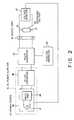
- Fig. 2 is a block diagram of a charging apparatus which may be used in the methodof the present invention;
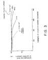
- Fig. 3 is a graph for illustrating cycle life characteristics of Li secondary batterycharged by different pulsed currents according to this invention in comparison with aconventional charging method by use of DC current;
- Fig. 4(a) and 4(b) are photographs each showing the microstructure of a surface ofa negative electrode of Li secondary battery, Fig. 4(a) being after charged by a pulsedcurrent, Fig. 4(b) being after charged by a DC current;
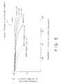
- Fig. 5 is a graph illustrating cycle life characteristics of Li secondary battery chargedby use of different pulsed current according to a second embodiment of this invention incomparison with a conventional charging method by use of DC current;
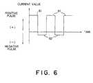
- Fig. 6 shows a waveform of a pulsed current which is used in a method according toa third embodiment of this invention; and
- Fig. 7 and 8 are graphs illustrating cycle life characteristics of Li secondary batterycharged according to the third embodiment of this invention, numbers of curvescorresponding to test numbers in Table 1.
- A secondary battery to which the present invention is applied is a known one.Description is, however, at first made about the secondary battery for the betterunderstanding of the present invention.
- Referring to Fig. 1, a typical example of a lithium (Li)
secondary battery 30comprises abattery case 31 which is generally used as a negative electrode terminal, and aninsulator ring 32 which is used as a cap of thebattery case 31. Apositive electrode terminal 33is adapted to theinsulator ring 32. Apositiveelectrode 34, anegative electrode 35, and aseparator 36between the positive and thenegative electrodes battery case 31. Theseparator 36 is impregnated with an electrolyte which is not shownin the figure. The positive and thenegative electrodes negative electrode terminals - In the shown example, the battery case is used asthe negative electrode terminal. However, there is knownanother type where the battery case is used as thepositive electrode terminal with a negative electrodeterminal being provided separate from the battery case.Further, the positive and the negative electrodes areshown wound together with the separator in spiral form inthe figure, but another type is also known where they areconcentrically disposed in the battery case.
- In the conventional charging method, a positiveDC voltage is applied across the positive and the
negative electrode terminals battery 30to make a DC current flow from thepositive electrode 34to thenegative electrode 35 through the electrolyte soas to charge the battery. - According to the present invention, a pulsedcurrent is supplied to the battery so as to charge thebattery.
- Referring to Fig. 2, a charging apparatussuitable for use in the method of the present inventioncomprises a
DC power supplier 41, apulse generator 42, afunction generator 43, and anoutput port 44. - The DC
power supplier 41 has aDC power source 45and a DC/DC converter 46. TheDC power source 45includes anAC power source 47 such as a commercial ACpower source and arectifier 48 for rectifying the ACpower to produce a rectified power. The DC/DC converter 46 regulates the rectified power to produce a regulatedDC power with a constant current. - The
pulse generator 42 is connected to theDCpower supplier 41 and generates a pulsed power from theDC power. The pulsed power is repeated with acontrollable frequency, a controllable duty ratio, and acontrollable waveform. - The
function generator 43 is connected to thepulse generator 42 and controls the pulsed power to setthe controllable frequency, controllable duty ratio, andcontrollable waveform into a predetermined frequency, apredetermined duty ratio, and a predetermined waveform. - The
output port 44 comprises a positive terminal(+) and a negative terminal (-) and is connected to thepulse generator 42. Theoutput port 44 is used forcharging a secondary battery therethrough. - Besides, the charging apparatus shown in thefigure is further provided with a
voltage detector 47 fordetecting completion of charge where the secondary battery is completely charged up to 100%. - In use of the charging apparatus, the
secondarybattery 30 is connected to theoutput port 44 with thepositive and thenegative electrode terminals output port 44. A power switch (notshown) is turned on at theDC power supplier 41. Then,the pulsed current is produced at thepulse generator 42and is supplied to thesecondary battery 30. Thus, thepulsed current flows from thepositive electrode terminal 33 to thenegative electrode terminal 31 of thesecondarybattery 30. In detail, the pulsed current flows from thepositive electrode 34 to thenegative electrode 35through the electrolyte in thesecondary battery 30 tothereby charge the secondary battery. - Now, examples according to the present inventionwill be described below.
- In order to estimate effects of the chargingmethod of the present invention as to the cycle lifecharacteristics of a lithium (Li) secondary battery, acharge-discharge cycle test was carried out for severalsamples of Li secondary battery.
- In the Li secondary battery, the positiveelectrode is made of a manganese dioxide, while thenegative electrode is made of lithium metal. Theelectrolyte is such a solution that a LiClO4 is melted inpropylene carbonate (PC) with a concentration of 1 N (normal).
- In the charge-discharge cycle test, the chargingoperation was performed to charge each of samples to acharged voltage of 3.5 V by use of the charging apparatusshown in Fig. 2. The pulsed current used for chargingwas differently adjusted for different samples to havedifferent pulse repetition frequencies of 100 Hz, 10 kHz,and 0.1 Hz and a constant pulse duty ratio of 50%. Eachpulse of the pulsed current was also adjusted to have aconstant positive pulse amplitude sufficient to make acurrent of 0.1 mA flow per 1 cm2 of the positiveelectrode of the battery. That is, the positive pulseamplitude is corresponding to a current density of 0.1mA/cm2 in the positive electrode of the battery. Thus,the maximum current density flowing through the positiveelectrode is 0.1 mA/cm2.
- For comparison, one of the samples was charged to3.5 V by use of a DC current having a positive levelcorresponding to a current density of 0.1 mA/cm2 in thepositive electrode of the battery.
- The discharge was performed by continuouslysupplying a current from the charged sample to a load ata rate of a current density of 0.1 mA/cm2 in the positiveelectrode until the battery voltage became 2.0 V. A timeperiod was measured for the voltage of each samplebattery dropped from 3.5 V to 2.0 V. A supplying currentwas also measured when the supplying voltage became 2.0V. A discharging capacity of each sample battery after each charging operation was calculated from the measuredtime period and the supplying current.
- Providing that an initial discharging capacityafter an initial charging operation is 100%, variation ofthe discharging capacity after each charging operation isshown in Fig. 3 as a relation between numbers ofcharge-discharge cycle and a deterioration rate of thebattery discharging capacity.
- It is noted from Fig. 3 that the samples chargedby use of a pulsed current according to the presentinvention are considerably low in deterioration ofbattery discharging capacity in comparison with thesample charged by use of DC current according to theconventional charging method.
- In order to seek for the grounds that cycle lifecharacteristics of the samples charged by the pulsedcurrent are superior to those charged by the DC current,as suggested in Fig. 3, microstructure of a surface of anegative electrode of each one of the samples is observedby use of a scanning electron microscope (SEM). Fig.4(a) shows the SEM photo of the sample charged by thepulsed current with the pulse repetition frequency of 10kHz and the pulse amplitude corresponding to the currentdensity of 0.1 mA/cm2. Fig. 4(b) shows that of thesample charged by the DC current corresponding to thecurrent density of 0.1 mA/cm2.
- It is noted from Figs. 4(a) and 4(b) that lithiumhas been deposited in a form of granules on the surface of the negative electrode of the sample charged by thepulsed current, while dendrite crystal has grown on thesurface of the negative electrode of the sample chargedby the DC current.
- In view of results of the above charge-dischargecycle test and the SEM photos, it is readily understoodthat a growth of the dendrite crystal on a surface of anegative electrode causes a deterioration of cycle lifecharacteristics and a short-circuit between a positiveand a negative electrodes of a Li secondary battery.
- Thus, the method according to the embodiment ofthe present invention can prevent the Li secondarybattery from being deteriorated in the cycle lifecharacteristics and short-circuited due to such a growthof the dendrite crystal.
- From different point of view, anothercharge-discharge cycle test was carried out for severalsamples of Li secondary battery which are experimentallyproduced by use of the similar materials to those of thesamples in Example 1.
- In the charge-discharge cycle test, the chargingoperation was performed to charge each of samples to acharged voltage of 3.5 V by use of the same chargingapparatus as that used in Example 1. Each pulsed currentused for charging was adjusted to have the constant pulserepetition frequency of 100 Hz and a pulse duty ratio of50%. The pulse of the pulsed current was differently adjusted for different samples to have different positivepulse amplitudes which are corresponding to differentcurrent densities of 1 µA/cm2, 0.1 mA/cm2, 1 mA/cm2, and100 mA/cm2 in the positive electrode of the battery.
- For comparison, two of the samples were chargedto 3.5 V by use of each DC current having differentpositive levels corresponding to current densities of 0.1mA/cm2 and 1 mA/cm2, respectively, in the positiveelectrode of the battery.
- It is also noted from Fig. 5 that the samplescharged by use of a pulsed current according to thepresent invention are considerably low in deteriorationof battery discharging capacity in comparison with thesample charged by use of DC current according to theconventional charging method.
- A further charge-discharge cycle test was carriedout for several samples of Li secondary battery whichwere experimentally produced by use of the similarmaterials to those of the samples in Examples 1 and 2.
- The charge-discharge cycle test was carried outunder the conditions described in Table 1.
- Referring to Fig. 6, a pulsed current supplied toeach of test samples shown in Table 1 comprises a
positive pulse 61 and anegative pulse 62 followingthereto which are repeated. Thepositive pulse 61 has apositive amplitude, while thenegative pulse 62 has anegative amplitude.CHARGING CONDITION (PULSED CURRENT) DISCHARGING CONDITION (DC CURRENT) PULSE REPETITION FREQUENCY/Hz CURRENT VALUE/ µAcm-2 CURRENT VALUE/ µAcm-2 (+) CHARGING DIRECTION (-) DISCHARGING DIRECTION DISCHARGE TEST SAMPLE 1 100 1 -0.25 -100 TEST SAMPLE 2100 100 -1 -100 TEST SAMPLE 3100 100 -10 -100 TEST SAMPLE 4 100 1 x 10⁵ -1 -100 TEST SAMPLE 5 100 1 x 10⁵ -10 -100 TEST SAMPLE 6 0.1 100 -10 -100 TEST SAMPLE 710000 100 -10 -100 COMPARED SAMPLE 100 (DC CURRENT) -100 DUTY RATIO: 50%
FINAL VOLTAGE: CHARGE 3.5V, DISCHARGE 2.0V - The positive amplitude was, as described in Table1, corresponding to first current densities of 1 µA/cm2to 1 x 10⁵ µA/cm2 (100 mA/cm2) in positive electrodes inthe
test samples 1 to 7. The negative amplitude wascorresponding to second current densities of 0.25 µA/cm2to 10 µA/cm2 which are less than the first currentdensity, as described in Table 1. - As described in Table 1, the pulsed current usedfor charging each of the
test samples 1 to 5 was adjustedto have a constant pulse repetition frequency of 100 Hzand a constant pulse duty ratio of 50%. The pulsedcurrent used for chargingtest samples 6 and 7 wasadjusted to have pulse repetition frequencies of 0.1 Hzand 10 kHz, respectively, and the constant pulse dutyratio of 50%. - The charging and the discharging operations wereperformed in the similar manner to that in Examples 1 and2, as will be understood in Table 1.
- For comparison, one of the samples was charged to3.5 V by use of DC current having a positive levelcorresponding to a current density of 0.1 mA/cm2 in thepositive electrode of the battery.
- Results of the charge-discharge cycle tests areshown in Figs. 7 and 8. Fig. 7 shows a result of
testsamples 1 to 5 which were charged by use of pulsedcurrents having the same pulse repetition frequency butdifferent positive and negative pulse amplitudes. Fig. 8shows a result oftest samples - It is noted from Figs. 7 and 8 that the samplescharged by use of the pulsed current according to thepresent Example are very low in deterioration of batterydischarging capacity in comparison with the sample charged by use of DC current according to the conventional charging method.
- The aforesaid second current density is not greater than a quarterof the aforesaid first current density so as not to elongate a charging time period.
- While this invention has thus far been describedwith respect to only several embodiments thereof, it willbe readily possible for those skilled in the art to putthis invention into practice in various other manners.For example, the pulsed current is not limited, to a pulsecurrent as illustrated in Fig. 6. Namely, a word "pulsedcurrent" in the instant specification may include such acurrent as having a sinusoidal waveform, such a currentas having a sawtooth waveform, and the like. Moreover,the charging apparatus illustrated in Fig. 2 does not have to beused to supply the pulsed current to the secondarybattery. Alternatively, a half-wave rectified currentmay be supplied to the secondary battery by use of an ACpower source and a rectifier.
Claims (1)
- A method for charging a secondary battery (30) comprising a positive electrode (34),a lithium negative electrode (35) and an electrolyte, said method comprising the steps of:(a) producing a pulsed current having a predetermined repetition frequency whichis between 0.1 Hz and 10KHz, inclusive, said pulsed current comprising apositive pulsed current and a negative pulsed current following thereto, whichare repeated, said positive pulsed current having a positive amplitude whichcorresponds to a first current density of 1µA/cm2 to 100 mA/cm2, inclusive,in said positive electrode, said negative pulsed current having anegative amplitude which corresponds to a second current density which is notgreater than a quarter of the first current density; and(b) supplying the pulsed current to the secondary battery to make the pulsedcurrent flow between the positive electrode (34) and the lithium negativeelectrode (35) through the electrolyte to thereby charge the secondary battery.
Applications Claiming Priority (6)
| Application Number | Priority Date | Filing Date | Title |
|---|---|---|---|
| JP335283/92 | 1992-11-19 | ||
| JP33528392 | 1992-11-19 | ||
| JP4335283AJPH06165403A (en) | 1992-11-19 | 1992-11-19 | Charging method of nickel-cadmium battery |
| JP339956/92 | 1992-12-21 | ||
| JP4339956AJPH06188026A (en) | 1992-12-21 | 1992-12-21 | Nickel-cadmium storage battery and charging method thereof |
| JP33995692 | 1992-12-21 |
Publications (3)
| Publication Number | Publication Date |
|---|---|
| EP0598470A2 EP0598470A2 (en) | 1994-05-25 |
| EP0598470A3 EP0598470A3 (en) | 1995-04-12 |
| EP0598470B1true EP0598470B1 (en) | 1999-07-14 |
Family
ID=26575129
Family Applications (1)
| Application Number | Title | Priority Date | Filing Date |
|---|---|---|---|
| EP93303089AExpired - LifetimeEP0598470B1 (en) | 1992-11-19 | 1993-04-21 | Method for charging a secondary battery by supplying pulsed current as charging current |
Country Status (5)
| Country | Link |
|---|---|
| US (1) | US5614805A (en) |
| EP (1) | EP0598470B1 (en) |
| AU (1) | AU667356B2 (en) |
| CA (1) | CA2094528C (en) |
| DE (1) | DE69325628T2 (en) |
Cited By (3)
| Publication number | Priority date | Publication date | Assignee | Title |
|---|---|---|---|---|
| CN107592025A (en)* | 2016-02-05 | 2018-01-16 | 广东欧珀移动通信有限公司 | Charging system, the charging method of terminal and power supply adaptor |
| US10910852B2 (en) | 2016-07-26 | 2021-02-02 | Guangdong Oppo Mobile Telecommunications Corp., Ltd. | Charging system, charging method, and power adapter |
| EP4123776A3 (en)* | 2021-07-14 | 2024-08-07 | SK On Co., Ltd. | Method for charging and discharging battery |
Families Citing this family (31)
| Publication number | Priority date | Publication date | Assignee | Title |
|---|---|---|---|---|
| GB2311410B (en)* | 1993-03-01 | 1997-12-10 | Tadiran Ltd | A method of enhancing the operational life of an electrochemical secondary cell |
| US5744935A (en)* | 1996-08-06 | 1998-04-28 | Khoury; Omar Fuad | Process and apparatus for nickel-cadmium battery revival |
| US5729116A (en)* | 1996-12-20 | 1998-03-17 | Total Battery Management, Inc. | Shunt recognition in lithium batteries |
| US5783929A (en)* | 1997-03-27 | 1998-07-21 | Taricco; Todd | Apparatus and method for recharging a battery |
| US6020722A (en)* | 1997-06-30 | 2000-02-01 | Compaq Computer Corporation | Temperature compensated voltage limited fast charge of nickel cadmium and nickel metal hybride battery packs |
| US6137268A (en)* | 1997-06-30 | 2000-10-24 | Compaq Computer Corporation | System with limited long-time-averaged battery charging rate |
| US6040684A (en)* | 1997-06-30 | 2000-03-21 | Compaq Computer Corporation | Lithium ion fast pulse charger |
| IL122416A0 (en)* | 1997-12-02 | 1998-06-15 | Electric Fuel Ltd | Battery |
| CA2277531A1 (en)* | 1998-07-27 | 2000-01-27 | Dominique G. Makar | Pulse modified invariant current battery charging method and apparatus |
| BR0012551B1 (en)* | 1999-07-19 | 2014-10-07 | 0891433 B C Ltd | METHOD FOR CHARGING A BATTERY, AND BATTERY CHARGER TO CHARGE A BATTERY |
| US6392385B1 (en)* | 1999-12-01 | 2002-05-21 | Jeremy Barker | Battery operation for extended cycle life |
| RU2180460C2 (en)* | 2000-01-05 | 2002-03-10 | Дувинг Валентин Георгиевич | Lead-acid cell charging process |
| RU2185009C2 (en)* | 2000-06-06 | 2002-07-10 | Открытое акционерное общество "Свердловэнерго" | Method and device for reconditioning nickel- cadmium storage cells |
| ATE316706T1 (en)* | 2001-05-28 | 2006-02-15 | 10Charge Elektrotechnikai Fejl | METHOD AND DEVICE FOR CHARGING A RECHARGEABLE BATTERY WITH NON-LIQUID ELECTROLYTE |
| RU2226019C2 (en)* | 2002-03-28 | 2004-03-20 | Сарапов Станислав Викторович | Method for charging and recovering storage batteries |
| US8188718B2 (en) | 2002-05-28 | 2012-05-29 | Advanced Battery Management, Llc | Method and apparatus for a remote battery charger with a self contained power source |
| GB2403609A (en)* | 2003-07-01 | 2005-01-05 | Univ Leicester | Pulse charging an electrochemical device |
| RU2258995C1 (en)* | 2003-11-27 | 2005-08-20 | ОАО "Научно-исследовательский проектно-конструкторский и технологический аккумуляторный институт" (ОАО "НИАИ "Источник") | Method for servicing lead cell or battery |
| FR2878381B1 (en)* | 2004-11-19 | 2008-06-13 | Peugeot Citroen Automobiles Sa | METHOD FOR CHARGING A BATTERY |
| JP4538418B2 (en)* | 2006-02-15 | 2010-09-08 | トヨタ自動車株式会社 | Secondary battery charge / discharge controller |
| RU2313863C1 (en)* | 2006-04-20 | 2007-12-27 | Открытое акционерное общество "Всероссийский научно-исследовательский и проектно-конструкторский институт электровозостроения" (ОАО "ВЭлНИИ") | Method for high-speed formation and recovery of sealed nickel-cadmium storage batteries by charging them with asymmetric current |
| RU2313862C1 (en)* | 2006-05-04 | 2007-12-27 | Государственное образовательное учреждение высшего профессионального образования "Южно-Российский государственный технический университет (Новочеркасский политехнический институт)" | Method for reducing polarization of lead battery plates under stochastic trickle charge conditions in pulsed power-recuperation drive system |
| US7834592B2 (en)* | 2007-09-27 | 2010-11-16 | Pulsetech Products Corporation | Circuit for generating triangular waveform having relatively short linear rise time and substantially long linear fall time |
| RU2437190C2 (en) | 2009-08-07 | 2011-12-20 | Геннадий Дмитриевич Платонов | Storage battery restoration method and device for its implementation |
| TWI435488B (en)* | 2011-01-25 | 2014-04-21 | Gennady Platonov | Method for recovering an accumulator battery and apparatus for performing thereof |
| EP3282550B1 (en) | 2016-02-05 | 2020-04-15 | Guangdong Oppo Mobile Telecommunications Corp., Ltd. | Adapter and charging control method |
| EP3567699B1 (en)* | 2016-07-26 | 2023-07-26 | Guangdong Oppo Mobile Telecommunications Corp., Ltd. | Charging device and method, power adapter and terminal |
| JP6633104B2 (en)* | 2016-07-26 | 2020-01-22 | オッポ広東移動通信有限公司 | Adapter and charge control method |
| CN111463512B (en)* | 2019-01-18 | 2021-12-03 | 北京纳米能源与系统研究所 | Charging method of lithium metal battery and lithium metal battery system |
| US12431728B2 (en)* | 2020-04-17 | 2025-09-30 | Iontra Inc | Systems and methods for electrochemical device charging and discharging |
| EP4248516A4 (en)* | 2020-12-16 | 2025-03-26 | Gbatteries Energy Canada Inc. | TEMPERATURE-BASED BATTERY CHARGING METHODS AND SYSTEMS |
Citations (2)
| Publication number | Priority date | Publication date | Assignee | Title |
|---|---|---|---|---|
| US4878007A (en)* | 1986-12-01 | 1989-10-31 | Brg Mechatronikai Vallalat | Method for charging nickel-cadmium batteries and circuit arrangement for carrying out the method |
| US4947124A (en)* | 1988-04-05 | 1990-08-07 | Habra Elektronik Gmbh | Method for charging a nickel-cadmium accumulator and simultaneously testing its condition |
Family Cites Families (11)
| Publication number | Priority date | Publication date | Assignee | Title |
|---|---|---|---|---|
| US3963976A (en)* | 1974-07-08 | 1976-06-15 | Utah Research & Development Co. | Pulsed current battery charging method and apparatus |
| EP0034003B1 (en)* | 1980-01-11 | 1985-04-24 | Rediffusion Radio Systems Limited | Battery charger |
| US4261629A (en)* | 1980-01-21 | 1981-04-14 | Amp Incorporated | Slotted plate terminal |
| US4661759A (en)* | 1984-08-16 | 1987-04-28 | Energy Research Corporation | Nickel-oxygen monitor cell system |
| EP0190078A3 (en)* | 1985-01-30 | 1987-04-08 | S.E.R.E.G.I.E. | Charging method for an electrochemical generator with a negative zinc electrode, and generator for using said method |
| JPS61290669A (en)* | 1985-06-19 | 1986-12-20 | Meidensha Electric Mfg Co Ltd | Operation of zinc-halogen secondary battery |
| US4645996A (en)* | 1985-10-25 | 1987-02-24 | General Electric Company | Rechargeable battery and electrical circuit for charging thereof |
| US4736150A (en)* | 1986-07-09 | 1988-04-05 | The United States Of America As Represented By The Secretary Of The Army | Method of increasing the useful life of rechargeable lithium batteries |
| JPS6481628A (en)* | 1987-09-18 | 1989-03-27 | Furukawa Battery Co Ltd | Method of charging storage battery |
| FR2689319A1 (en)* | 1992-03-26 | 1993-10-01 | Sorapec | Bipolar electrode for storage battery. |
| JP2732760B2 (en)* | 1991-10-23 | 1998-03-30 | 金井重要工業株式会社 | Nonwoven fabric separator for battery and method for producing the same |
- 1993
- 1993-04-20USUS08/050,830patent/US5614805A/ennot_activeExpired - Fee Related
- 1993-04-21DEDE69325628Tpatent/DE69325628T2/ennot_activeExpired - Fee Related
- 1993-04-21CACA002094528Apatent/CA2094528C/ennot_activeExpired - Fee Related
- 1993-04-21AUAU37042/93Apatent/AU667356B2/ennot_activeCeased
- 1993-04-21EPEP93303089Apatent/EP0598470B1/ennot_activeExpired - Lifetime
Patent Citations (2)
| Publication number | Priority date | Publication date | Assignee | Title |
|---|---|---|---|---|
| US4878007A (en)* | 1986-12-01 | 1989-10-31 | Brg Mechatronikai Vallalat | Method for charging nickel-cadmium batteries and circuit arrangement for carrying out the method |
| US4947124A (en)* | 1988-04-05 | 1990-08-07 | Habra Elektronik Gmbh | Method for charging a nickel-cadmium accumulator and simultaneously testing its condition |
Cited By (5)
| Publication number | Priority date | Publication date | Assignee | Title |
|---|---|---|---|---|
| CN107592025A (en)* | 2016-02-05 | 2018-01-16 | 广东欧珀移动通信有限公司 | Charging system, the charging method of terminal and power supply adaptor |
| US10320217B2 (en) | 2016-02-05 | 2019-06-11 | Guangdong Oppo Mobile Telecommunications Corp., Ltd. | Charging system and method, and power adapter |
| US10418835B2 (en) | 2016-02-05 | 2019-09-17 | Guangdong Oppo Mobile Telecommunications Corp., Ltd. | Charging system and method, and power adapter |
| US10910852B2 (en) | 2016-07-26 | 2021-02-02 | Guangdong Oppo Mobile Telecommunications Corp., Ltd. | Charging system, charging method, and power adapter |
| EP4123776A3 (en)* | 2021-07-14 | 2024-08-07 | SK On Co., Ltd. | Method for charging and discharging battery |
Also Published As
| Publication number | Publication date |
|---|---|
| US5614805A (en) | 1997-03-25 |
| DE69325628D1 (en) | 1999-08-19 |
| AU667356B2 (en) | 1996-03-21 |
| CA2094528C (en) | 2002-09-24 |
| EP0598470A2 (en) | 1994-05-25 |
| CA2094528A1 (en) | 1994-05-20 |
| DE69325628T2 (en) | 1999-12-02 |
| AU3704293A (en) | 1994-06-16 |
| EP0598470A3 (en) | 1995-04-12 |
Similar Documents
| Publication | Publication Date | Title |
|---|---|---|
| EP0598470B1 (en) | Method for charging a secondary battery by supplying pulsed current as charging current | |
| JP3216133B2 (en) | Non-aqueous electrolyte secondary battery charging method | |
| EP0067590B1 (en) | Method and apparatus for charging a battery | |
| EP0067589B1 (en) | Method and apparatus for testing a battery | |
| US6366056B1 (en) | Battery charger for lithium based batteries | |
| US20190222051A1 (en) | Methods and systems for recharging a battery | |
| EP2594006B1 (en) | Method and apparatus for recharging a battery | |
| JP2771036B2 (en) | Method and apparatus for charging, defrosting and formatting a storage battery | |
| JP4121945B2 (en) | Method and apparatus for charging a rechargeable battery with a non-liquid electrolyte | |
| EP0623986A1 (en) | Battery charger | |
| DE19641989A1 (en) | Double battery charger for nickel-metal-hydride or lithium-ion types e.g. for portable radios | |
| US11710978B2 (en) | Battery charger and method for charging a battery | |
| JP3558523B2 (en) | Charging method for non-aqueous secondary batteries | |
| WO1987007781A1 (en) | Method and apparatus for improving electrochemical processes | |
| EA000240B1 (en) | Control and termination of a battery charging process | |
| JP2000182677A (en) | Rechargeable battery charger | |
| JP3216595B2 (en) | Rechargeable battery charger | |
| JP3271138B2 (en) | Rechargeable battery charger and charging method | |
| JP3722091B2 (en) | Battery assembly life discriminator for charger | |
| JPH065310A (en) | Secondary battery charge control method | |
| JPH05316663A (en) | Charging method for storage battery | |
| Harer | High performance charge control system | |
| JPH1127867A (en) | Battery charger | |
| Kumai | An approach to extending the cycle life of Li/MoS2 cells | |
| JPH07270504A (en) | Battery life determination device |
Legal Events
| Date | Code | Title | Description |
|---|---|---|---|
| PUAI | Public reference made under article 153(3) epc to a published international application that has entered the european phase | Free format text:ORIGINAL CODE: 0009012 | |
| AK | Designated contracting states | Kind code of ref document:A2 Designated state(s):DE FR GB IT | |
| PUAL | Search report despatched | Free format text:ORIGINAL CODE: 0009013 | |
| AK | Designated contracting states | Kind code of ref document:A3 Designated state(s):DE FR GB IT | |
| 17P | Request for examination filed | Effective date:19950906 | |
| 17Q | First examination report despatched | Effective date:19960227 | |
| GRAG | Despatch of communication of intention to grant | Free format text:ORIGINAL CODE: EPIDOS AGRA | |
| 17Q | First examination report despatched | Effective date:19980402 | |
| GRAG | Despatch of communication of intention to grant | Free format text:ORIGINAL CODE: EPIDOS AGRA | |
| GRAH | Despatch of communication of intention to grant a patent | Free format text:ORIGINAL CODE: EPIDOS IGRA | |
| GRAH | Despatch of communication of intention to grant a patent | Free format text:ORIGINAL CODE: EPIDOS IGRA | |
| GRAA | (expected) grant | Free format text:ORIGINAL CODE: 0009210 | |
| AK | Designated contracting states | Kind code of ref document:B1 Designated state(s):DE FR GB IT | |
| REF | Corresponds to: | Ref document number:69325628 Country of ref document:DE Date of ref document:19990819 | |
| ET | Fr: translation filed | ||
| PLBE | No opposition filed within time limit | Free format text:ORIGINAL CODE: 0009261 | |
| STAA | Information on the status of an ep patent application or granted ep patent | Free format text:STATUS: NO OPPOSITION FILED WITHIN TIME LIMIT | |
| 26N | No opposition filed | ||
| REG | Reference to a national code | Ref country code:GB Ref legal event code:IF02 | |
| REG | Reference to a national code | Ref country code:FR Ref legal event code:CD | |
| PGFP | Annual fee paid to national office [announced via postgrant information from national office to epo] | Ref country code:DE Payment date:20040429 Year of fee payment:12 | |
| PG25 | Lapsed in a contracting state [announced via postgrant information from national office to epo] | Ref country code:IT Free format text:LAPSE BECAUSE OF NON-PAYMENT OF DUE FEES Effective date:20050421 | |
| PG25 | Lapsed in a contracting state [announced via postgrant information from national office to epo] | Ref country code:DE Free format text:LAPSE BECAUSE OF NON-PAYMENT OF DUE FEES Effective date:20051101 | |
| PGFP | Annual fee paid to national office [announced via postgrant information from national office to epo] | Ref country code:FR Payment date:20060410 Year of fee payment:14 | |
| PGFP | Annual fee paid to national office [announced via postgrant information from national office to epo] | Ref country code:GB Payment date:20060419 Year of fee payment:14 | |
| GBPC | Gb: european patent ceased through non-payment of renewal fee | Effective date:20070421 | |
| PG25 | Lapsed in a contracting state [announced via postgrant information from national office to epo] | Ref country code:GB Free format text:LAPSE BECAUSE OF NON-PAYMENT OF DUE FEES Effective date:20070421 | |
| PG25 | Lapsed in a contracting state [announced via postgrant information from national office to epo] | Ref country code:FR Free format text:LAPSE BECAUSE OF NON-PAYMENT OF DUE FEES Effective date:20070430 |