EP0597135B1 - Device for reading and writing on magnetic cards - Google Patents
Device for reading and writing on magnetic cardsDownload PDFInfo
- Publication number
- EP0597135B1 EP0597135B1EP92119018AEP92119018AEP0597135B1EP 0597135 B1EP0597135 B1EP 0597135B1EP 92119018 AEP92119018 AEP 92119018AEP 92119018 AEP92119018 AEP 92119018AEP 0597135 B1EP0597135 B1EP 0597135B1
- Authority
- EP
- European Patent Office
- Prior art keywords
- card
- cards
- holding drum
- channel
- assigned
- Prior art date
- Legal status (The legal status is an assumption and is not a legal conclusion. Google has not performed a legal analysis and makes no representation as to the accuracy of the status listed.)
- Expired - Lifetime
Links
Images
Classifications
- G—PHYSICS
- G06—COMPUTING OR CALCULATING; COUNTING
- G06K—GRAPHICAL DATA READING; PRESENTATION OF DATA; RECORD CARRIERS; HANDLING RECORD CARRIERS
- G06K13/00—Conveying record carriers from one station to another, e.g. from stack to punching mechanism
- G06K13/02—Conveying record carriers from one station to another, e.g. from stack to punching mechanism the record carrier having longitudinal dimension comparable with transverse dimension, e.g. punched card
- B—PERFORMING OPERATIONS; TRANSPORTING
- B65—CONVEYING; PACKING; STORING; HANDLING THIN OR FILAMENTARY MATERIAL
- B65H—HANDLING THIN OR FILAMENTARY MATERIAL, e.g. SHEETS, WEBS, CABLES
- B65H29/00—Delivering or advancing articles from machines; Advancing articles to or into piles
- B65H29/58—Article switches or diverters
- B—PERFORMING OPERATIONS; TRANSPORTING
- B65—CONVEYING; PACKING; STORING; HANDLING THIN OR FILAMENTARY MATERIAL
- B65H—HANDLING THIN OR FILAMENTARY MATERIAL, e.g. SHEETS, WEBS, CABLES
- B65H2701/00—Handled material; Storage means
- B65H2701/10—Handled articles or webs
- B65H2701/17—Nature of material
- B65H2701/176—Cardboard
Definitions
- the inventionrelates to a device for reading and writing magnetic cards with a coding and reading unit, a printer and a cylindrical recording drum, which is provided with a diametrically continuous card slot and can be rotated about an axis of rotation running transverse to the longitudinal axis of the card.
- Such devices for reading and writing magnetic cardsare known for example from EP-A1-0 118 730. They are able to evaluate and process magnetic cards inserted into the device in every possible position and orientation, the correct position for reading and further processing the magnetic cards being achieved by correspondingly rotating the recording drum.
- the inventionhas for its object to further develop such a device such that at least one further machine-readable card, for example a prepaid card, a credit card and / or a customer card, is also used for the further processing of the magnetic card inserted into the device can be.
- at least one further machine-readable cardfor example a prepaid card, a credit card and / or a customer card
- the solution to this problem by the inventionis characterized in that at least two parking shafts are assigned to the receiving drum, which can be rotated through at least 180 °, at least one of which is used for temporarily holding the magnetic card to be processed and at least one for temporarily holding another card required for the processing operation is provided.
- the magnetic card inserted into the devicefor example to pay for a product or a service, using a further machine-readable card, without having a separate device for this additional card own entry opening required.
- Both the magnetic card to be processed further and at least one further machine-readable cardcan be inserted through the same input opening in the device according to the invention.
- Both the magnetic card and the other machine-readable cardare each received in one of the parking slots when the other card is read, encoded or rewritten. In this way it is thus possible to carry out the further processing of a magnetic card with the aid of at least one further machine-readable card in one and the same device.
- the parking shaftsare arranged at an angle to the feed direction of the cards to be processed and a through-channel is arranged in the feed direction through which the cards can be fed to further processing downstream of the device or through which material required for the processing process is fed to the device can, which has a length exceeding the diameter of the recording drum, such as balance sheet or diagnostic printouts.
- the design according to the invention of a through-channel running in the feed directionthus also permits the processing and output of materials which exceed the diameter of the take-up drum, such as, for example, balance or diagnostic printouts of greater length.
- the inventionfurther proposes to assign at least one feed channel for card raw material to the receiving drum.
- Thiscan be card rolls or card stacks, act preferably folded card stacks from which magnetic cards made of paper, cardboard and thick and thin plastic can be produced, which are provided in the middle and / or laterally with magnetic strips, but can also contain contact or contactless chips.
- the receiving drumcan be assigned a card feed channel opening into a card collecting container, so that cards to be drawn in are removed directly from the device according to the invention.
- the receiving drumcan, however, also be assigned at least one additional card output channel which is oriented at an angle to the feed direction of the cards to be processed.
- Such an additional card output channelis advantageous, for example, if the user, after entering his magnetic card, has, for example, passed a barrier opened with the aid of his magnetic card, so that it is expedient to remove the further processed magnetic card from another point of the device according to the invention.
- an additional channel leading to a chip card reading stationis assigned to the receiving drum according to a further feature of the invention.
- the rotary drive of the take-up drumis formed by a stepper motor.
- the basic position of the take-up drumcan be determined by a Hall sensor position sensor.
- the inventionproposes a second motor for driving the transport means arranged in the receiving drum for the respective card.
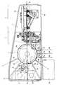
- the drawingshows a housing 1 provided with a lower cover 1a and an upper cover 1b. It is provided with an input opening 1d, behind which an encoding and reading unit 2 is arranged in the housing 1.
- This known coding and reading unit 2is followed in the feed direction by a printer 3, which in the exemplary embodiment shown is formed by a thermal printer known per se.
- a take-up drum 4which in the exemplary embodiment is rotatably mounted through 360 °.
- This cylindrical take-up drum 4is provided with a diametrically continuous card slot 4a. It is driven, for example, via a toothed belt 4b by a motor 5 designed as a stepping motor.
- a position sensor 6designed as a Hall sensor.
- the receiving drum 4is assigned two parking shafts 7a, 7b, in each of which a machine-readable card in credit card format can be stored during the processing of a further card in the same processing operation. This way it is possible to get one include another machine-readable card in the processing of a magnetic card.
- the order in which the cards belonging to an operation are input through the input opening 1dis just as arbitrary as their output from the housing 1.
- an entry card designed as a magnetic cardfor example for a swimming pool
- the magnetic cardis read in the encoding and reading unit 2, transported through the printer 3 into the receiving drum 4 and brought into the parking slot 7a by rotating this receiving drum 4.
- a machine-readable cash value cardis then inserted into the housing 1, read and transferred into the parking shaft 7b with the aid of the receiving drum 4. If the amount on the cash value card is not sufficient to pay the fee, another cash value card can be inserted into the housing 1 and read. If the amount of the second cash value card is not sufficient to fully pay the fee, all three cards can be returned one after the other.
- the printer 3it is possible to use the printer 3 to apply a line print on one of the two surfaces of the cash value card (s) which indicates the last residual value in each case. In this case, too, the three cards are then issued in any order from the housing 1 through the input opening 1d.
- this chip card reading station 9is designed for contact-type chip cards. It comprises two pivoted angular levers 9a, the mutually facing angular arms of which project into the additional channel 8. These angle levers 9a are loaded by tension springs 9b and carry angled contact springs 9c on their angle arms lying outside the additional channel 8.
- contact springs 9care automatically placed on the corresponding transponders of the chip cards when the card is inserted into the additional channel 8 to the end.
- the edge of the card lying at the front in the insertion directionpivots the angle levers 9a against the force of the tension springs 9b, so that the angled ends of the contact springs 9c sit on the corresponding points on the card.
- the cardis completely withdrawn into the card slot 4a of the receiving drum 4 and either parked or returned in a parking slot 7a or 7b.
- the through-channel 10aligned in the feed direction of the cards on the side opposite the printer 3 in the housing 1 the recording drum 4 arranged.
- the cardscan be fed out of the housing 1 for further processing.
- materialcan also be output from the input opening 1d of the housing 1.
- the receiving drum 4 in the exemplary embodimentis assigned 3 feed channels 11a, 11b, 11c, through which card raw material 12a, 12b and 12c of the receiving drum 4 can be supplied.
- This card raw material 12a, 12b, 12cis, for example, card rolls or preferably folded card stacks.
- the card raw material 12a, 12b, 12cis separated in a suitable manner after feeding a predetermined length into the card slot 4a of the receiving drum 4 by knives 13a, 13b, 13c, which at the end of the respective feed channel 11a or 11b or 11c facing the receiving drum 4 are arranged.
- Invalid, worn, invalidated or otherwise not removed cardscan be drawn in through a card feed channel 14 pointing obliquely downwards. They are fed to a collecting container 15 arranged below the card feed channel 14.
- the exemplary embodimentfinally reveals that the receiving drum 4 is assigned a further card output channel 16 which is oriented at an angle to the direction of feed of the cards to be processed. Via this card issuing channel 16, magnetic cards can be removed from the housing 1, for example, when the user has entered a lock after entering his magnetic card, which has been opened due to the processing of the magnetic card he has entered through the input opening 1d.
- the drawingshows a further drive motor 17, which drives the transport means arranged in the receiving drum 4 for the respective card via a toothed belt 17a.
- these means of transportare not shown in the drawing.
- an electromagnetic clutchalso not shown, which is controlled by an electromagnet arranged in the receiving drum 4
- the transport means arranged in the various channels 7a, 7b, 8, 10, 14, 16 and 11a, 11b and 11ccan also be driven by the drive motor 17 always be driven when cards have to be transported in the respective channel.
- the take-up drum 4with its associated shafts 7a, 7b, 10, 11a, 11b, 11c and 14 and 16 is rotatably mounted about a pivot point 1c.
- the device for reading and writing to magnetic cards explained above on the basis of an exemplary embodimentis able to process, for example, machine-readable cards made of paper, cardboard and thick and thin plastic in credit card format, which are provided with central and / or side magnetic strips.
- machine-readable cardsmade of paper, cardboard and thick and thin plastic in credit card format, which are provided with central and / or side magnetic strips.
- the receiving drum 4acting in the manner of a switch or turntable to bring the cards into different parking positions, using endless material for processing or card raw material 12a, 12b, 12c for the production of machine-readable cards.
- the coding and reading unit 2is equipped on both sides with magnetic heads for side strip processing and a magnetic head for central strip processing.
- the cardcan be rotated by 180 ° with the help of the rotatable take-up drum 4. This is also the case with chip cards if they are not inserted with the side facing the chip contacts or the chip antenna. Overall, this results in a compact device with a mechanically and electrically cost-effective structure, which can be used for a large number of applications.
Landscapes
- Engineering & Computer Science (AREA)
- Mechanical Engineering (AREA)
- Physics & Mathematics (AREA)
- General Physics & Mathematics (AREA)
- Theoretical Computer Science (AREA)
- Devices For Checking Fares Or Tickets At Control Points (AREA)
Description
Translated fromGermanDie Erfindung betrifft eine Vorrichtung zum Lesen und Beschreiben von Magnetkarten mit einer Codier- und Leseeinheit, einem Drucker und einer zylindrischen Aufnahmetrommel, die mit einem diametral durchgehenden Kartenschacht versehen und um eine quer zur Kartenlängsachse verlaufende Drehachse verdrehbar ist.The invention relates to a device for reading and writing magnetic cards with a coding and reading unit, a printer and a cylindrical recording drum, which is provided with a diametrically continuous card slot and can be rotated about an axis of rotation running transverse to the longitudinal axis of the card.
Derartige Vorrichtungen zum Lesen und Beschreiben von Magnetkarten sind beispielsweise aus der EP-A1-0 118 730 bekannt. Sie sind in der Lage, in jeder möglichen Lage und Orientierung in die Vorrichtung eingeführte Magnetkarten auszuwerten und weiter zu verarbeiten, wobei die korrekte Lage zum Lesen und Weiterverarbeiten der Magnetkarten durch entsprechendes Drehen der Aufnahmetrommel erreicht wird.Such devices for reading and writing magnetic cards are known for example from EP-A1-0 118 730. They are able to evaluate and process magnetic cards inserted into the device in every possible position and orientation, the correct position for reading and further processing the magnetic cards being achieved by correspondingly rotating the recording drum.
Der Erfindung liegt die Aufgabe zugrunde, eine derartige Vorrichtung derart weiter zu bilden, daß für die Weiterverarbeitung der in die Vorrichtung eingeführten Magnetkarte auch mindestens eine weitere, ebenfalls in die Vorrichtung einzuführende maschinenlesbare Karte, beispielsweise eine Wertkarte, eine Kreditkarte und/oder eine Kundenkarte herangezogen werden kann.The invention has for its object to further develop such a device such that at least one further machine-readable card, for example a prepaid card, a credit card and / or a customer card, is also used for the further processing of the magnetic card inserted into the device can be.
Die Lösung dieser Aufgabenstellung durch die Erfindung ist dadurch gekennzeichnet, daß der mindestens um 180° verdrehbaren Aufnahmetrommel mindestens zwei Parkschächte zugeordnet sind, von denen mindestens einer zur zeitweisen Aufnahme der zu verarbeitenden Magnetkarte und mindestens einer zur zeitweisen Aufnahme einer weiteren, für den Verarbeitungsvorgang benötigten Karte vorgesehen ist.The solution to this problem by the invention is characterized in that at least two parking shafts are assigned to the receiving drum, which can be rotated through at least 180 °, at least one of which is used for temporarily holding the magnetic card to be processed and at least one for temporarily holding another card required for the processing operation is provided.
Durch die erfindungsgemäße Zuordnung mindestens zweier Parkschächte zu der verdrehbaren Aufnahmetrommel wird die Möglichkeit geschaffen, die beispielsweise zur Bezahlung einer Ware oder einer Dienstleistung in die Vorrichtung eingeführte Magnetkarte unter Verwendung einer weiteren maschinenlesbaren Karte zu verarbeiten, ohne daß es für diese weitere Karte einer separaten Vorrichtung mit eigener Eingabeöffnung bedarf. Sowohl die weiter zu verarbeitende Magnetkarte als auch mindestens eine weitere maschinenlesbare Karte können bei der erfindungsgemäßen Vorrichtung durch dieselbe Eingabeöffnung eingeführt werden. Sowohl die Magnetkarte als auch die weitere maschinenlesbare Karte werden jeweils in einem der Parkschächte aufgenommen, wenn die jeweils andere Karte gelesen, codiert oder umgeschrieben wird. Auf diese Weise ist es somit möglich, die Weiterverarbeitung einer Magnetkarte mit Hilfe mindestens einer weiteren maschinenlesbaren Karte in ein und derselben Vorrichtung vorzunehmen.By assigning at least two parking shafts to the rotatable receiving drum according to the invention, it is possible to process the magnetic card inserted into the device, for example to pay for a product or a service, using a further machine-readable card, without having a separate device for this additional card own entry opening required. Both the magnetic card to be processed further and at least one further machine-readable card can be inserted through the same input opening in the device according to the invention. Both the magnetic card and the other machine-readable card are each received in one of the parking slots when the other card is read, encoded or rewritten. In this way it is thus possible to carry out the further processing of a magnetic card with the aid of at least one further machine-readable card in one and the same device.
Gemäß einem weiteren Merkmal der Erfindung sind die Parkschächte unter einem Winkel zur Zuführrichtung der zu verarbeitenden Karten angeordnet und in Zuführrichtung ein Durchgangskanal angeordnet, durch den die Karten einer der Vorrichtung nachgeschalteten Weiterverarbeitung zugeführt werden können oder durch den der Vorrichtung für den Verarbeitungsvorgang benötigtes Material zugeführt werden kann, das eine den Durchmesser der Aufnahmetrommel übersteigende Länge hat, wie beispielsweise Bilanz- oder Diagnoseausdrucke. Die erfindungsgemäße Ausbildung eines in Zuführrichtung verlaufenden Durchgangskanals gestattet somit auch die Verarbeitung und Ausgabe von den Durchmesser der Aufnahmetrommel übersteigenden Materialien, wie beispielsweise Bilanz- oder Diagnoseausdrucke größerer Länge.According to a further feature of the invention, the parking shafts are arranged at an angle to the feed direction of the cards to be processed and a through-channel is arranged in the feed direction through which the cards can be fed to further processing downstream of the device or through which material required for the processing process is fed to the device can, which has a length exceeding the diameter of the recording drum, such as balance sheet or diagnostic printouts. The design according to the invention of a through-channel running in the feed direction thus also permits the processing and output of materials which exceed the diameter of the take-up drum, such as, for example, balance or diagnostic printouts of greater length.
Mit der Erfindung wird weiterhin vorgeschlagen, der Aufnahmetrommel mindestens einen Zufuhrkanal für Kartenrohmaterial zuzuordnen. Hierbei kann es sich um Kartenrollen oder Kartenstapel, vorzugsweise gefaltete Kartenstapel handeln, aus denen Magnetkarten aus Papier, Karton sowie Dick- und Dünnplastik hergestellt werden können, die mittig und/oder seitlich mit Magnetstreifen versehen sind, aber auch kontaktbehaftete oder kontaktlose Chips enthalten können.The invention further proposes to assign at least one feed channel for card raw material to the receiving drum. This can be card rolls or card stacks, act preferably folded card stacks from which magnetic cards made of paper, cardboard and thick and thin plastic can be produced, which are provided in the middle and / or laterally with magnetic strips, but can also contain contact or contactless chips.
In an sich bekannter Weise kann der Aufnahmetrommel ein in einem Kartenauffangbehälter mündender Karteneinzugkanal zugeordnet sein, so daß einzuziehende Karten unmittelbar aus der erfindungsgemäßen Vorrichtung entfernt werden.In a manner known per se, the receiving drum can be assigned a card feed channel opening into a card collecting container, so that cards to be drawn in are removed directly from the device according to the invention.
Der Aufnahmetrommel kann aber auch mindestens ein unter einem Winkel zur Zufuhrrichtung der zu verarbeitenden Karten ausgerichteter zusätzlicher Kartenausgabekanal zugeordnet sein. Ein derartiger zusätzlicher Kartenausgabekanal ist beispielsweise dann von Vorteil, wenn der Benutzer nach Eingabe seiner Magnetkarte beispielsweise eine mit Hilfe seiner eingegebenen Magnetkarte geöffnete Sperre passiert hat, so daß es zweckmäßig ist, die weiterverarbeitete Magnetkarte einer anderen Stelle der erfindungsgemäßen Vorrichtung zu entnehmen.The receiving drum can, however, also be assigned at least one additional card output channel which is oriented at an angle to the feed direction of the cards to be processed. Such an additional card output channel is advantageous, for example, if the user, after entering his magnetic card, has, for example, passed a barrier opened with the aid of his magnetic card, so that it is expedient to remove the further processed magnetic card from another point of the device according to the invention.
Sofern die erfindungsgemäße Vorrichtung auch für die Verarbeitung von kontaktbehafteten oder kontaktlosen Chipkarten bestimmt ist, wird gemäß einem weiteren Merkmal der Erfindung der Aufnahmetrommel ein zu einer Chipkarten-Lesestation führender Zusatzkanal zugeordnet.If the device according to the invention is also intended for the processing of contact or contactless chip cards, an additional channel leading to a chip card reading station is assigned to the receiving drum according to a further feature of the invention.
Der Drehantrieb der Aufnahmetrommel wird erfindungsgemäß durch einen Schrittmotor gebildet. Die Grundposition der Aufnahmetrommel kann gemäß einem weiteren Merkmal der Erfindung durch einen Hallsensor-Positionsgeber bestimmt werden. Schließlich wird mit der Erfindung vorgeschlagen, einen zweiten Motor zum Antrieb der in der Aufnahmetrommel angeordneten Transportmittel für die jeweilige Karte vorzusehen.According to the invention, the rotary drive of the take-up drum is formed by a stepper motor. According to a further feature of the invention, the basic position of the take-up drum can be determined by a Hall sensor position sensor. Finally, the invention proposes a second motor for driving the transport means arranged in the receiving drum for the respective card.
Auf der Zeichnung ist ein Ausführungsbeispiel der erfindungsgemäßen Vorrichtung in einer schematischen Seitenansicht dargestellt.In the drawing, an embodiment of the device according to the invention is shown in a schematic side view.
Die Zeichnung zeigt ein mit einer unteren Abdeckung 1a und einer oberen Abdeckung 1b versehenes Gehäuse 1. Es ist mit einer Eingabeöffnung 1d versehen, hinter der eine Codier- und Lese-Einheit 2 im Gehäuse 1 angeordnet ist. An diese bekannte Codier- und Lese-Einheit 2 schließt sich in Einzugrichtung ein Drucker 3 an, der beim dargestellten Ausführungsbeispiel durch einen an sich bekannten Thermodrucker gebildet ist.The drawing shows a housing 1 provided with a
Diese zum Codieren und Lesen bzw. zum Bedrucken von Magnetkarten bestimmten Geräte sind innerhalb des Gehäuses 1 in einer Linie mit einer Aufnahmetrommel 4 angeordnet, die beim Ausführungsbeispiel um 360° verdrehbar gelagert ist. Diese zylindrische Aufnahmetrommel 4 ist mit einem diametral durchgehenden Kartenschacht 4a versehen. Sie wird beispielsweise über einen Zahnriemen 4b von einem als Schrittmotor ausgebildeten Motor 5 angetrieben. Hierbei wird die Grundstellung der Aufnahmetrommel 4 im Gehäuse 1 durch einen als Hallsensor ausgebildeten Positionsgeber 6 bestimmt.These devices intended for coding and reading or for printing magnetic cards are arranged within the housing 1 in a line with a take-
Der Aufnahmetrommel 4 sind beim dargestellten Ausführungsbeispiel zwei Parkschächte 7a, 7b zugeordnet, in denen jeweils eine maschinenlesbare Karte im Kreditkartenformat während der Verarbeitung einer weiteren Karte im selben Verarbeitungsvorgang abgelegt werden kann. Auf diese Weise ist es möglich, eine weitere maschinenlesbare Karte in den Verarbeitungsvorgang einer Magnetkarte einzubeziehen. Die Reihenfolge der Eingabe der zu einem Arbeitsgang gehörenden Karten durch die Eingabeöffnung 1d ist ebenso beliebig wie deren Ausgabe aus dem Gehäuse 1.In the exemplary embodiment shown, the
So ist es beispielsweise möglich, eine als Magnetkarte ausgebildete Eintrittskarte, beispielsweise für ein Schwimmbad, zur Nachbezahlung einer Gebühr in das Gehäuse 1 einzuführen. Die Magnetkarte wird hierbei in der Codier- und Leseeinheit 2 gelesen, durch den Drucker 3 hindurch in die Aufnahmetrommel 4 transportiert und durch Drehung dieser Aufnahmetrommel 4 in den Parkschacht 7a gebracht. Anschließend wird eine maschinenlesbare Geldwertkarte ins Gehäuse 1 eingeführt, gelesen und mit Hilfe der Aufnahmetrommel 4 in den Parkschacht 7b überführt. Sofern der Betrag auf der Geldwertkarte zur Bezahlung der Gebühr nicht ausreicht, kann eine weitere Geldwertkarte ins Gehäuse 1 eingeführt und gelesen werden. Sollte auch der Betrag der zweiten Geldwertkarte zur restlosen Zahlung der Gebühr nicht ausreichen, können alle drei Karten nacheinander zurückgegeben werden.For example, it is possible to insert an entry card designed as a magnetic card, for example for a swimming pool, into the housing 1 for subsequent payment of a fee. The magnetic card is read in the encoding and
Sofern der Wert der Geldwertkarten ausreicht, die Gebühr zu zahlen, wird der jeweilige Betrag von der/den Geldwertkarte(n) abgebucht. Hierbei ist es möglich, auf einer der beiden Oberflächen der Geldwertkarte(n) einen Zeilenaufdruck mit Hilfe des Druckers 3 aufzubringen, der den jeweils letzten Restwert angibt. Auch in diesem Fall werden anschließend die drei Karten in beliebiger Reihenfolge aus dem Gehäuse 1 durch die Eingabeöffnung 1d ausgegeben.If the value of the prepaid cards is sufficient to pay the fee, the respective amount will be debited from the prepaid card (s). In this case, it is possible to use the
Als Karten können hierbei unterschiedliche Karten im Kreditkartenformat verwendet werden, die aus Papier, Karton, Dick- oder Dünnplastik bestehen und als maschinenlesbare Datenträger jeweils einzeln oder kombiniert Mittel- und Seiten-Magnetstreifen aufweisen. Sofern kontaktbehaftete oder kontaktlose Chips auf den Karten Verwendung finden, ist der Aufnahmetrommel 4 ein Zusatzkanal 8 zugeordnet, der zu einer Chipkarten-Lesestation 9 führt. Beim Ausführungsbeispiel ist diese Chipkarten-Lesestation 9 für kontaktbehaftete Chipkarten ausgeführt. Sie umfaßt zwei verschwenkbar gelagerte Winkelhebel 9a, deren gegeneinander weisende Winkelarme in den Zusatzkanal 8 hineinragen. Diese Winkelhebel 9a sind durch Zugfedern 9b belastet und tragen an ihren außerhalb des Zusatzkanals 8 liegenden Winkelarmen abgewinkelte Kontaktfedern 9c. Diese Kontaktfeder 9c werden selbsttätig auf die entsprechenden Transponder der Chipkarten aufgesetzt, wenn die Karte bis zum Ende in den Zusatzkanal 8 eingeschoben wird. Hierbei verschwenkt der in Einschubrichtung vorn liegende Rand der Karte die Winkelhebel 9a entgegen der Kraft der Zugfedern 9b, so daß sich die abgewinkelten Enden der Kontaktfedern 9c auf die entsprechenden Stellen der Karte aufsetzen. Nach entsprechender Prüfung der Chipdaten wird die Karte vollständig in den Kartenschacht 4a der Aufnahmetrommel 4 zurückgezogen und entweder in einem Parkschacht 7a oder 7b geparkt oder zurückgegeben.Different cards in credit card format can be used as cards, made of paper, cardboard, There are thick or thin plastics and each have a central or side magnetic strip as a machine-readable data carrier, either individually or in combination. If contact or contactless chips are used on the cards, the receiving
Auf diese Weise ist es möglich, in den Arbeitsvorgang zur Verarbeitung der in einem Parkschacht 7a oder 7b geparkten Magnetkarte auch Chipkarten einzubeziehen. Für kontaktlose Chipkarten ist anstelle der beschriebenen Chipkarten-Lesestation 9 eine entsprechende Sende-Empfangs-Einrichtung im Zusatzkanal 8 untergebracht.In this way it is possible to include chip cards in the work process for processing the magnetic card parked in a
Beim dargestellten Ausführungsbeispiel ist im Gehäuse 1 weiterhin ein in Zuführrichtung der Karten ausgerichteter Durchgangskanal 10 auf der dem Drucker 3 gegenüberliegenden Seite der Aufnahmetrommel 4 angeordnet. Durch diesen Durchgangskanal 10 können die Karten aus dem Gehäuse 1 heraus einer nachgeschalteten Weiterverarbeitung zugeführt werden. Außerdem besteht die Möglichkeit, durch den Durchgangskanal 10 hindurch dem Drucker 3 sowie der Codier- und Leseeinheit 2 bei der Verarbeitung zu berücksichtigendes Material zuzuführen, dessen Länge den Durchmesser der Aufnahmetrommel 4 übersteigt, wie beispielsweise Bilanz- oder Diagnoseausdrucke. Dieses Material kann darüber hinaus aus der Eingabeöffnung 1d des Gehäuses 1 ausgegeben werden.In the exemplary embodiment shown, there is also a through-
Um mit Hilfe des Druckers 3 und/oder der Codier- und Lese-Einheit 2 maschinenlesbare Karten herstellen zu können, sind der Aufnahmetrommel 4 beim Ausführungsbeispiel 3 Zufuhrkanäle 11a, 11b, 11c zugeordnet, durch die hindurch Kartenrohmaterial 12a, 12b und 12c der Aufnahmetrommel 4 zugeführt werden kann. Bei diesem Kartenrohmaterial 12a, 12b, 12c handelt es sich beispielsweise um Kartenrollen oder vorzugsweise gefaltete Kartenstapel. Das Kartenrohmaterial 12a, 12b, 12c wird auf geeignete Weise nach Zufuhr einer vorgegebenen Länge in den Kartenschacht 4a der Aufnahmetrommel 4 durch Messer 13a, 13b, 13c abgetrennt, die an dem der Aufnahmetrommel 4 zugewandten Ende des jeweiligen Zufuhrkanals 11a bzw. 11b bzw. 11c angeordnet sind.In order to be able to produce machine-readable cards with the aid of the
Durch einen schräg nach unten weisenden Karteneinzugkanal 14 können ungültige, abgenutzte, entwertete oder auf andere Weise nicht entnommene Karten eingezogen werden. Sie werden einem unterhalb des Karteneinzugkanals 14 angeordneten Auffangbehälter 15 zugeführt.Invalid, worn, invalidated or otherwise not removed cards can be drawn in through a
Das Ausführungsbeispiel läßt schließlich erkennen, daß der Aufnahmetrommel 4 ein weiterer, unter einem Winkel zur Zufuhrrichtung der zu verarbeiteten Karten ausgerichteter Kartenausgabekanal 16 zugeordnet ist. Über diesen Kartenausgabekanal 16 können beispielsweise Magnetkarten dem Gehäuse 1 entnommen werden, wenn der Benutzer nach der Eingabe seiner Magnetkarte beispielsweise eine Sperre durchschritten hat, die infolge der Verarbeitung der von ihm durch die Eingabeöffnung 1d eingegebenen Magnetkarte geöffnet worden ist.The exemplary embodiment finally reveals that the
Die Zeichnung zeigt schließlich einen weiteren Antriebsmotor 17, der über einen Zahnriemen 17a die in der Aufnahmetrommel 4 angeordneten Transportmittel für die jeweilige Karte antreibt. Diese Transportmittel sind der besseren Übersichtlichkeit wegen auf der Zeichnung nicht dargestellt. Mit Hilfe einer ebenfalls nicht dargestellten elektromagnetischen Kupplung, die von einem in der Aufnahmetrommel 4 angeordneten Elektromagneten gesteuert wird, können auch die in den verschiedenen Kanälen 7a, 7b, 8, 10, 14, 16 sowie 11a, 11b und 11c angeordneten Transportmittel vom Antriebsmotor 17 immer dann angetrieben werden, wenn Karten im jeweiligen Kanal transportiert werden müssen.Finally, the drawing shows a
Zu Servicezwecken ist die Aufnahmetrommel 4 mit ihren zugehörigen Schächten 7a, 7b, 10, 11a, 11b, 11c sowie 14 und 16 um einen Drehpunkt 1c drehbar gelagert.For service purposes, the take-
Die voranstehend anhand eines Ausführungsbeispiels erläuterte Vorrichtung zum Lesen und Beschreiben von Magnetkarten ist in der Lage, beispielsweise im Kreditkartenformat vorliegende maschinenlesbare Karten aus Papier, Karton sowie Dick- und Dünnplastik zu verarbeiten, die mit Mittel- und/oder Seiten-Magnetstreifen versehen sind. Es können gleichzeitig mehrere, in beliebiger Reihenfolge durch die Eingabeöffnung 1d eingeführte Karten verarbeitet werden, wobei die Aufnahmetrommel 4 in der Art einer Weiche oder Drehscheibe wirkt, um die Karten in unterschiedliche Parkpositionen zu bringen, Endlosmaterial für die Verarbeitung heranzuziehen oder Kartenrohmaterial 12a, 12b, 12c zur Herstellung von maschinenlesbaren Karten zuzuführen. Um in jeder der vier möglichen Lagen zugeführte Magnetkarten verarbeiten zu können, ist die Codier- und Leseeinheit 2 beidseitig mit Magnetköpfen für Seitenstreifenverarbeitung und einem Magnetkopf für Mittelstreifenverarbeitung ausgestattet. Sofern der Magnetstreifen einer eingeschobenen Karte unten und der entsprechende Magnetkopf oben ist, wird mit Hilfe der drehbaren Aufnahmetrommel 4 eine Wendung der Karte um die Längsachse um 180° vorgenommen. Diese Wendung erfolgt auch bei Chipkarten, wenn diese nicht mit der den Chipkontakten oder der Chipantenne zugewandten Seite eingeschoben werden. Insgesamt ergibt sich eine kompakte Vorrichtung mit mechanisch und elektrisch kostengünstigem Aufbau, die für eine Vielzahl von Anwendungsfällen eingesetzt werden kann.The device for reading and writing to magnetic cards explained above on the basis of an exemplary embodiment is able to process, for example, machine-readable cards made of paper, cardboard and thick and thin plastic in credit card format, which are provided with central and / or side magnetic strips. Several cards inserted in any order through the input opening 1d can be processed at the same time, the receiving
- 11
- Gehäusecasing
- 1a1a
- Abdeckungcover
- 1b1b
- Abdeckungcover
- 1c1c
- Drehpunktpivot point
- 1d1d
- EingabeöffnungEntry opening
- 22nd
- Codier- und Lese-EinheitCoding and reading unit
- 33rd
- Druckerprinter
- 44th
- AufnahmetrommelRecording drum
- 4a4a
- KartenschachtCard slot
- 4b4b
- ZahnriemenTiming belt
- 55
- Motorengine
- 66
- PositionsgeberPosition transmitter
- 7a7a
- ParkschachtParking slot
- 7b7b
- ParkschachtParking slot
- 88th
- ZusatzkanalAdditional channel
- 99
- Chipkarten-LesestationSmart card reading station
- 9a9a
- WinkelhebelAngle lever
- 9b9b
- ZugfederTension spring
- 9c9c
- KontaktfederContact spring
- 1010th
- DurchgangskanalThrough channel
- 11a11a
- ZufuhrkanalFeed channel
- 11b11b
- ZufuhrkanalFeed channel
- 11c11c
- ZufuhrkanalFeed channel
- 12a12a
- KartenrohmaterialMap raw material
- 12b12b
- KartenrohmaterialMap raw material
- 12c12c
- KartenrohmaterialMap raw material
- 13a13a
- Messerknife
- 13b13b
- Messerknife
- 13c13c
- Messerknife
- 1414
- KarteneinzugkanalCard feed channel
- 1515
- AuffangbehälterCollecting container
- 1616
- KartenausgabekanalCard issue channel
- 1717th
- AntriebsmotorDrive motor
- 17a17a
- ZahnriemenTiming belt
Claims (9)
- Device for reading and writing on magnetic cards, having an encoding and reading unit (2), a printer (3), preferably a thermal printer, and a cylindrical holding drum (4) which is provided with a card slot (4a) passing diametrically through it and can be rotated about an axis of rotation extending transverse to the card longitudinal axis, characterized in that the holding drum (4), which can be rotated at least through 180°, is assigned at least two parking slots (7a, 7b), at least one of which is provided for the temporary holding of the magnetic card to be processed, and at least one for the temporary holding of another card which is needed for the processing operation.
- Device according to Claim 1, characterized in that the parking slots (7a, 7b) are arranged at an angle to the feed direction of the cards to be processed, and in the feed direction there is arranged a through channel (10) for the further processing of the cards and/or for the feeding of material which is additionally to be processed in the device and has a length exceeding the diameter of the holding drum (4), such as balance print-outs or diagnostic print-outs.
- Device according to Claim 1 or 2, characterized in that the holding drum (4) is assigned at least one feed channel (11a, 11b, 11c) for card raw material (12a, 12b, 12c).
- Device according to at least one of Claims 1 to 3, characterized in that the holding drum (4) is assigned a card drawing-in channel (14) which opens into a card collecting container (15).
- Device according to at least one of Claims 1 to 4, characterized in that the holding drum (4) is assigned at least one additional card delivery channel (16) which is aligned at an angle to the feed direction of the cards to be processed.
- Device according to at least one of Claims 1 to 5, characterized in that the holding drum (4) is assigned a supplementary channel (8) leading to a chip card reading station (9).
- Device according to at least one of Claims 1 to 6, characterized in that the rotary drive of the holding drum (4) is formed by a stepping motor (5).
- Device according to at least one of Claims 1 to 7, characterized in that the basic position of the holding drum (4) can be determined by means of a Hall-sensor position transmitter (6).
- Device according to at least one of Claims 1 to 8, characterized in that a second motor (17) is provided to drive the transport means, arranged in the holding drum (4), for the respective card.
Priority Applications (6)
| Application Number | Priority Date | Filing Date | Title |
|---|---|---|---|
| DE59208665TDE59208665D1 (en) | 1992-11-06 | 1992-11-06 | Device for reading and writing magnetic cards |
| EP92119018AEP0597135B1 (en) | 1992-11-06 | 1992-11-06 | Device for reading and writing on magnetic cards |
| ES92119018TES2103865T3 (en) | 1992-11-06 | 1992-11-06 | DEVICE FOR THE READING AND WRITING OF MAGNETIC CARDS. |
| FI931288AFI101434B1 (en) | 1992-11-06 | 1993-03-23 | Device for reading and writing magnetic cards |
| NO931485ANO304088B1 (en) | 1992-11-06 | 1993-04-22 | Device for reading and description of magnetic cards |
| AU42011/93AAU654625B2 (en) | 1992-11-06 | 1993-07-16 | Device to read and write on magnetic cards |
Applications Claiming Priority (1)
| Application Number | Priority Date | Filing Date | Title |
|---|---|---|---|
| EP92119018AEP0597135B1 (en) | 1992-11-06 | 1992-11-06 | Device for reading and writing on magnetic cards |
Publications (2)
| Publication Number | Publication Date |
|---|---|
| EP0597135A1 EP0597135A1 (en) | 1994-05-18 |
| EP0597135B1true EP0597135B1 (en) | 1997-07-02 |
Family
ID=8210213
Family Applications (1)
| Application Number | Title | Priority Date | Filing Date |
|---|---|---|---|
| EP92119018AExpired - LifetimeEP0597135B1 (en) | 1992-11-06 | 1992-11-06 | Device for reading and writing on magnetic cards |
Country Status (6)
| Country | Link |
|---|---|
| EP (1) | EP0597135B1 (en) |
| AU (1) | AU654625B2 (en) |
| DE (1) | DE59208665D1 (en) |
| ES (1) | ES2103865T3 (en) |
| FI (1) | FI101434B1 (en) |
| NO (1) | NO304088B1 (en) |
Families Citing this family (14)
| Publication number | Priority date | Publication date | Assignee | Title |
|---|---|---|---|---|
| DE19644306C2 (en)* | 1996-10-24 | 1999-04-08 | Kunz Gmbh | Device for personalizing identification cards |
| GB9722551D0 (en)* | 1997-10-25 | 1997-12-24 | Ncr Int Inc | Card reader |
| DE19840811C2 (en) | 1998-09-07 | 2003-04-17 | Kunz Gmbh | Device for personalizing identification cards |
| EP1114387A1 (en) | 1998-09-14 | 2001-07-11 | Fargo Electronics, Inc. | Card printer and encoder |
| JP3744719B2 (en)* | 1999-04-15 | 2006-02-15 | 日立オムロンターミナルソリューションズ株式会社 | Medium issuing device and card issuing device |
| US7213755B2 (en)* | 1999-10-21 | 2007-05-08 | Cubic Corporation | System for rapidly dispensing and adding value to fare cards |
| MXPA02008366A (en)* | 2000-03-01 | 2002-12-13 | Zih Corp | Contact programmer. |
| US7399131B2 (en) | 2001-03-05 | 2008-07-15 | Fargo Electronics, Inc. | Method and Device for forming an ink-receptive card substrate |
| US7430762B2 (en) | 2002-03-01 | 2008-09-30 | Fargo Electronics, Inc. | Identification card manufacturing security |
| FR2843818B1 (en)* | 2002-08-21 | 2004-12-10 | Schlumberger Systems & Service | READ / WRITE DEVICE FOR MAGNETIC CARDS AND TICKETS |
| US7620815B2 (en) | 2003-02-21 | 2009-11-17 | Fargo Electronics, Inc. | Credential production using a secured consumable supply |
| EP1668587A2 (en) | 2003-09-11 | 2006-06-14 | Fargo Electronics, Inc. | Identification card manufacturing system supply ordering and diagnostic report |
| US8099187B2 (en) | 2005-08-18 | 2012-01-17 | Hid Global Corporation | Securely processing and tracking consumable supplies and consumable material |
| RO126347B1 (en) | 2010-06-24 | 2017-09-29 | Mb Telecom Ltd S.R.L. | Method and system for securing the use of magnetic strip cards |
Family Cites Families (2)
| Publication number | Priority date | Publication date | Assignee | Title |
|---|---|---|---|---|
| FR2599349B1 (en)* | 1986-07-03 | 1989-02-24 | Bull Sa | TEMPORARY STORAGE DEVICE FOR FLAT ITEMS |
| JPH0764467B2 (en)* | 1988-09-06 | 1995-07-12 | 沖電気工業株式会社 | Temporary stacking device |
- 1992
- 1992-11-06EPEP92119018Apatent/EP0597135B1/ennot_activeExpired - Lifetime
- 1992-11-06DEDE59208665Tpatent/DE59208665D1/ennot_activeExpired - Lifetime
- 1992-11-06ESES92119018Tpatent/ES2103865T3/ennot_activeExpired - Lifetime
- 1993
- 1993-03-23FIFI931288Apatent/FI101434B1/enactiveIP Right Grant
- 1993-04-22NONO931485Apatent/NO304088B1/ennot_activeIP Right Cessation
- 1993-07-16AUAU42011/93Apatent/AU654625B2/ennot_activeCeased
Also Published As
| Publication number | Publication date |
|---|---|
| AU654625B2 (en) | 1994-11-10 |
| FI931288A0 (en) | 1993-03-23 |
| EP0597135A1 (en) | 1994-05-18 |
| AU4201193A (en) | 1994-06-23 |
| FI101434B (en) | 1998-06-15 |
| DE59208665D1 (en) | 1997-08-07 |
| FI101434B1 (en) | 1998-06-15 |
| NO931485L (en) | 1994-05-09 |
| NO304088B1 (en) | 1998-10-19 |
| NO931485D0 (en) | 1993-04-22 |
| ES2103865T3 (en) | 1997-10-01 |
| FI931288A7 (en) | 1994-05-07 |
Similar Documents
| Publication | Publication Date | Title |
|---|---|---|
| DE69003515T2 (en) | Method and device for producing admission tickets. | |
| EP0597135B1 (en) | Device for reading and writing on magnetic cards | |
| DE69017605T2 (en) | Storage device for envelopes and single sheets. | |
| DE69421389T2 (en) | AUTOMATIC CONTROL AND INSERTION PROCEDURE OF IMPRESSED CARDS | |
| DE2456255C2 (en) | Card processing device | |
| DE69821860T2 (en) | card reader | |
| DE69800638T2 (en) | Switch for documents | |
| DE69325686T2 (en) | Magnetic and optical code reader | |
| EP1433124A2 (en) | Use of an rfid label for labelling an object to be transported with regard to the destination thereof in addition to a system, method, printer and tag for the same | |
| DE202016009054U1 (en) | Card printing mechanism with card return path | |
| DE3118687A1 (en) | DEVICE FOR DISPENSING VALUE-CONTAINING PAPER AND OTHER DOCUMENTS | |
| EP1880863A1 (en) | Process and device for manufacturing printed products composed of a block of sheets and a cover | |
| DE2307193A1 (en) | INPUT CONTROL FOR DOCUMENTS FOR THE USE OF AUTOMATIC MACHINES | |
| AT401437B (en) | SELF-CASHING MONITORING SYSTEM | |
| DE9302481U1 (en) | Parking card for fee-based operation of a parking barrier | |
| DE10049432A1 (en) | Accepting sheet material items, e.g. bank notes, involves associating each group of received items with at least one separating arrangement before or during acceptance or during processing | |
| EP0341524A1 (en) | Process and device for providing personalized mailing units comprising at least two articles | |
| DE3516460A1 (en) | DEVICE FOR TEMPORARY STORAGE OF RECEIPTS | |
| DE2134701A1 (en) | Device for dispensing objects | |
| EP0986023B1 (en) | Device for personalisation of ID-cards | |
| DE19811131B4 (en) | Installation and procedure for preparing letters for mailing | |
| CH625634A5 (en) | ||
| WO2004039711A1 (en) | Card buffer for temporarily buffering cards in card-processing systems | |
| DE69910845T2 (en) | HUMAN AND MACHINE INTERFACE METHOD AND DEVICE FOR A PROCESSING DEVICE FOR TICKET CARDS CONTAINING A MAGNETIC STRIP | |
| DE3875725T2 (en) | DEVICE AND METHOD FOR PROCESSING DOCUMENTS. |
Legal Events
| Date | Code | Title | Description |
|---|---|---|---|
| PUAI | Public reference made under article 153(3) epc to a published international application that has entered the european phase | Free format text:ORIGINAL CODE: 0009012 | |
| 17P | Request for examination filed | Effective date:19930819 | |
| AK | Designated contracting states | Kind code of ref document:A1 Designated state(s):CH DE ES FR GB LI NL SE | |
| GRAG | Despatch of communication of intention to grant | Free format text:ORIGINAL CODE: EPIDOS AGRA | |
| GRAH | Despatch of communication of intention to grant a patent | Free format text:ORIGINAL CODE: EPIDOS IGRA | |
| 17Q | First examination report despatched | Effective date:19961209 | |
| GRAH | Despatch of communication of intention to grant a patent | Free format text:ORIGINAL CODE: EPIDOS IGRA | |
| GRAA | (expected) grant | Free format text:ORIGINAL CODE: 0009210 | |
| AK | Designated contracting states | Kind code of ref document:B1 Designated state(s):CH DE ES FR GB LI NL SE | |
| RIN1 | Information on inventor provided before grant (corrected) | Inventor name:CRYNEN, NORBERT, DIPL.-ING. Inventor name:MILLER, GERT | |
| ET | Fr: translation filed | ||
| REG | Reference to a national code | Ref country code:CH Ref legal event code:NV Representative=s name:E. BLUM & CO. PATENTANWAELTE Ref country code:CH Ref legal event code:EP | |
| GBT | Gb: translation of ep patent filed (gb section 77(6)(a)/1977) | Effective date:19970704 | |
| REF | Corresponds to: | Ref document number:59208665 Country of ref document:DE Date of ref document:19970807 | |
| REG | Reference to a national code | Ref country code:ES Ref legal event code:FG2A Ref document number:2103865 Country of ref document:ES Kind code of ref document:T3 | |
| PLBE | No opposition filed within time limit | Free format text:ORIGINAL CODE: 0009261 | |
| STAA | Information on the status of an ep patent application or granted ep patent | Free format text:STATUS: NO OPPOSITION FILED WITHIN TIME LIMIT | |
| 26N | No opposition filed | ||
| REG | Reference to a national code | Ref country code:GB Ref legal event code:IF02 | |
| REG | Reference to a national code | Ref country code:CH Ref legal event code:PFA Owner name:SCHEIDT & BACHMANN GMBH Free format text:SCHEIDT & BACHMANN GMBH#BREITE STRASSE 132#D-41238 MOENCHENGLADBACH (DE) -TRANSFER TO- SCHEIDT & BACHMANN GMBH#BREITE STRASSE 132#D-41238 MOENCHENGLADBACH (DE) | |
| PGFP | Annual fee paid to national office [announced via postgrant information from national office to epo] | Ref country code:CH Payment date:20081114 Year of fee payment:17 Ref country code:NL Payment date:20081113 Year of fee payment:17 | |
| PGFP | Annual fee paid to national office [announced via postgrant information from national office to epo] | Ref country code:ES Payment date:20081121 Year of fee payment:17 | |
| PGFP | Annual fee paid to national office [announced via postgrant information from national office to epo] | Ref country code:SE Payment date:20081114 Year of fee payment:17 | |
| PGFP | Annual fee paid to national office [announced via postgrant information from national office to epo] | Ref country code:FR Payment date:20081113 Year of fee payment:17 | |
| PGFP | Annual fee paid to national office [announced via postgrant information from national office to epo] | Ref country code:GB Payment date:20081117 Year of fee payment:17 | |
| PGFP | Annual fee paid to national office [announced via postgrant information from national office to epo] | Ref country code:DE Payment date:20091130 Year of fee payment:18 | |
| REG | Reference to a national code | Ref country code:NL Ref legal event code:V1 Effective date:20100601 | |
| EUG | Se: european patent has lapsed | ||
| REG | Reference to a national code | Ref country code:CH Ref legal event code:PL | |
| GBPC | Gb: european patent ceased through non-payment of renewal fee | Effective date:20091106 | |
| REG | Reference to a national code | Ref country code:FR Ref legal event code:ST Effective date:20100730 | |
| PG25 | Lapsed in a contracting state [announced via postgrant information from national office to epo] | Ref country code:NL Free format text:LAPSE BECAUSE OF NON-PAYMENT OF DUE FEES Effective date:20100601 Ref country code:CH Free format text:LAPSE BECAUSE OF NON-PAYMENT OF DUE FEES Effective date:20091130 Ref country code:FR Free format text:LAPSE BECAUSE OF NON-PAYMENT OF DUE FEES Effective date:20091130 Ref country code:LI Free format text:LAPSE BECAUSE OF NON-PAYMENT OF DUE FEES Effective date:20091130 | |
| PG25 | Lapsed in a contracting state [announced via postgrant information from national office to epo] | Ref country code:GB Free format text:LAPSE BECAUSE OF NON-PAYMENT OF DUE FEES Effective date:20091106 | |
| REG | Reference to a national code | Ref country code:ES Ref legal event code:FD2A Effective date:20110325 | |
| PG25 | Lapsed in a contracting state [announced via postgrant information from national office to epo] | Ref country code:SE Free format text:LAPSE BECAUSE OF NON-PAYMENT OF DUE FEES Effective date:20091107 | |
| PG25 | Lapsed in a contracting state [announced via postgrant information from national office to epo] | Ref country code:ES Free format text:LAPSE BECAUSE OF NON-PAYMENT OF DUE FEES Effective date:20110314 | |
| REG | Reference to a national code | Ref country code:DE Ref legal event code:R119 Ref document number:59208665 Country of ref document:DE Effective date:20110601 Ref country code:DE Ref legal event code:R119 Ref document number:59208665 Country of ref document:DE Effective date:20110531 | |
| PG25 | Lapsed in a contracting state [announced via postgrant information from national office to epo] | Ref country code:ES Free format text:LAPSE BECAUSE OF NON-PAYMENT OF DUE FEES Effective date:20091107 Ref country code:DE Free format text:LAPSE BECAUSE OF NON-PAYMENT OF DUE FEES Effective date:20110531 |