EP0596826B1 - Shuffling method for a digital videotape recorder - Google Patents
Shuffling method for a digital videotape recorderDownload PDFInfo
- Publication number
- EP0596826B1 EP0596826B1EP93630083AEP93630083AEP0596826B1EP 0596826 B1EP0596826 B1EP 0596826B1EP 93630083 AEP93630083 AEP 93630083AEP 93630083 AEP93630083 AEP 93630083AEP 0596826 B1EP0596826 B1EP 0596826B1
- Authority
- EP
- European Patent Office
- Prior art keywords
- data
- interleaving
- segment
- deinterleaving
- data stream
- Prior art date
- Legal status (The legal status is an assumption and is not a legal conclusion. Google has not performed a legal analysis and makes no representation as to the accuracy of the status listed.)
- Expired - Lifetime
Links
- 238000000034methodMethods0.000titleclaimsdescription36
- 230000006870functionEffects0.000claimsdescription13
- 239000000872bufferSubstances0.000claimsdescription12
- 230000000694effectsEffects0.000claimsdescription10
- 230000003139buffering effectEffects0.000claimsdescription7
- 238000010586diagramMethods0.000description8
- 102100026992DermcidinHuman genes0.000description1
- BDAGIHXWWSANSR-UHFFFAOYSA-MFormateChemical compound[O-]C=OBDAGIHXWWSANSR-UHFFFAOYSA-M0.000description1
- 101000911659Homo sapiens DermcidinProteins0.000description1
- 239000000654additiveSubstances0.000description1
- 230000000996additive effectEffects0.000description1
- 230000005540biological transmissionEffects0.000description1
- 238000005056compactionMethods0.000description1
- 238000010276constructionMethods0.000description1
- 238000007796conventional methodMethods0.000description1
- 230000001934delayEffects0.000description1
- 230000003111delayed effectEffects0.000description1
- 230000001419dependent effectEffects0.000description1
- 238000005192partitionMethods0.000description1
Images


Classifications
- H—ELECTRICITY
- H04—ELECTRIC COMMUNICATION TECHNIQUE
- H04N—PICTORIAL COMMUNICATION, e.g. TELEVISION
- H04N5/00—Details of television systems
- H04N5/76—Television signal recording
- H04N5/91—Television signal processing therefor
- H04N5/93—Regeneration of the television signal or of selected parts thereof
- H04N5/94—Signal drop-out compensation
- H04N5/945—Signal drop-out compensation for signals recorded by pulse code modulation
- H—ELECTRICITY
- H04—ELECTRIC COMMUNICATION TECHNIQUE
- H04N—PICTORIAL COMMUNICATION, e.g. TELEVISION
- H04N5/00—Details of television systems
- H04N5/76—Television signal recording
- H04N5/91—Television signal processing therefor
- H04N5/92—Transformation of the television signal for recording, e.g. modulation, frequency changing; Inverse transformation for playback
- H04N5/926—Transformation of the television signal for recording, e.g. modulation, frequency changing; Inverse transformation for playback by pulse code modulation
- H—ELECTRICITY
- H04—ELECTRIC COMMUNICATION TECHNIQUE
- H04N—PICTORIAL COMMUNICATION, e.g. TELEVISION
- H04N5/00—Details of television systems
- H04N5/76—Television signal recording
- H04N5/78—Television signal recording using magnetic recording
- H04N5/782—Television signal recording using magnetic recording on tape
- H04N5/783—Adaptations for reproducing at a rate different from the recording rate
Definitions
- the present inventionrelates to a digital video cassette recorder (VCR), and more particularly to an apparatus for and a method of interleaving/deinterleaving for a digital VCR which can effectively correct errors occurring in recording or reproduction of compressed data and improve error correction capability, especially in variable speed reproduction.
- VCRdigital video cassette recorder
- the errors occurring in recording and reproduction with a digital VCRmay be classified as random errors and burst errors. Random errors independently occur in digital signal lines due to additive noise during signal processing, and burst error is successive error occurring with respect to a bit stream of transmission data under the influence of tape condition, and so on. Burst error can be corrected by being replaced with random errors through an interleaving/deinterleaving process.
- a conventional interleaving apparatus for a digital VCRincludes outer coder 1 for performing outer coding with respect to an input compressed data stream and successively outputting the data stream with an outer code symbol added thereto, first sector array memory 2 for successively storing the data outputted from outer coder 1, and inner coder 3 for reading the data stored in first sector array memory 2 in an order different from that in storing the data to first sector array memory 2, performing inner coding, outputting and recording the data with inner code symbol added thereto on a tape via a head.
- the interleaving apparatusis also provided with inner decoder 4 for decoding only data having the inner code symbol among the data reproduced from the tape, detecting errors in the data and performing interleaving with respect to such detected errors, second sector array memory 5 for distributively storing the interleaved data from inner decoder 4, and outer decoder 6 for reading out data from second sector array memory 5 in an order different from that in writing the data and performing decoding with respect to data having the outer code symbol to correct the errors.
- inner decoder 4for decoding only data having the inner code symbol among the data reproduced from the tape, detecting errors in the data and performing interleaving with respect to such detected errors
- second sector array memory 5for distributively storing the interleaved data from inner decoder 4
- outer decoder 6for reading out data from second sector array memory 5 in an order different from that in writing the data and performing decoding with respect to data having the outer code symbol to correct the errors.
- outer coder 1when the compressed data stream as shown in FIG. 2A is inputted, outer coder 1 performs outer coding in a vertical direction with respect to a series of symbols of the input data as shown in FIG. 2B and outputs data having the outer code symbol. Then, a redundancy is added to the data having the outer code symbol as shown in FIG. 2C and the redundancy-added data is stored in first sector array memory 2 in the order shown in FIG. 2D.
- Inner coder 3reads out the data from first sector array memory 2 in an order different from that in storing the data and performs interleaving to add the inner code symbol to the data. Accordingly, the order of the data is changed, being different from that of the input data, causing a burst error to be replaced by random errors.
- the data stream interleaved as described aboveis then inner-coded by inner coder 3, with the result that strong error correction coding (ECC) is performed.
- ECCerror correction coding
- Inner decoder 4decodes the data having the inner code symbol among the data having the inner and outer code symbols reproduced from the tape and detects and corrects the errors. That is, in correcting the errors, inner decoder 4 performs interleaving with respect to the errors which exist beyond its capability and distributively stores the interleaved data still having errors in second sector array memory 5. Outer decoder 6 performs outer decoding with respect to the data stored in second sector array memory 5 to correct the remaining errors, and thereby various kinds of errors occurring in reproduction in a digital VCR can be corrected and prevented.
- the conventional apparatus as described abovethus provides a strong capability to correct various errors occurring in reproduction of data and is suitable for use in a digital VCR for professional purposes.
- the VCR headin high speed play such as a picture search mode, passes across various tape tracks and the head trace region in a track, as well as the size of a sector array memory in the conventional apparatus, is inversely proportional to the degree of high speed.
- the VCR head in high speed playhas a nonlinear trace as shown in FIG. 4C, and this causes the maximum interleaving region for ECC to be further restricted in comparison to the linear head trace. Also, in high speed play, the head continually passes the track portion of the same position due to the restricted interleaving region, and the image data of the same picture portion is extracted. Accordingly, in order to obtain the image data of other picture portions, data allocation for rearranging the data recording position is required.
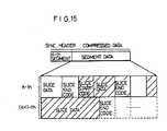
- the data segments reproduced by the conventional apparatusare classified into complete segments and incomplete segments, and the data segment is composed of slices which are the variable unit in which the image data and other information are compressed and compacted. Accordingly, as shown in FIG. 15, several slices may exist in the K-th segment while a slice may exist over two segments as shown in (k + 1)-th segment.
- Such slicesmay be performed with variable length coding (VLC) or compressed at different rates in encoding a high quality image or a normal image.
- VLCvariable length coding
- the lengths of the respective compressed data streamsmay appear to be different from one another, even though the respective image information of the same amount are compressed. Accordingly, in order to perfectly perform the variable length decoding (VLD) in a decoder, a complete bit stream should be reproduced in the unit of slice.
- VLDvariable length decoding
- EP-A-0 508 602discloses a video-audio digital recording apparatus comprising an analog/digital converter for converting analog signals to digital signals when recording data on a cassette tape; interleave RAM for storing a blocked video signal in a unit of a block; high-efficiency encoding circuit for compressing the video signal which is read out from the interleave RAM and randomly performing the process of reading the video signal from the interleave RAM; and video error collection encoder for encoding the compressed video signal outputted from the high-efficiency encoding circuit for error correction.
- the apparatuscomprises deinterleaving elements operated to the opposite effect.
- the interleave RAMinterleaves a digital video signal of one block comprising a plurality of pixels outputted from audio-video converter only once in a unit of block.
- the process of interleaving/deinterleaving the compressed datais performed irrespective of the regional space.
- the apparatuscomprises :
- an interleaving/deinterleaving method for a digital VCRaccording to the independent method claims.
- the methodcomprises the steps of:
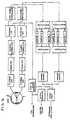
- FIG. 3shows an embodiment of the interleaving/deinterleaving apparatus for a digital VCR according to the present invention.
- the apparatuscomprises source encoder 10 for encoding an input image data stream, memory mapper 20 for storing and reading out the image data stream encoded by source encoder 10 in the unit of segment, interleaving controller 30 for restricting an interleaving region in accordance with a header information in line with a predetermined maximum speed, inter-segment interleaver 40 for performing inter-segment interleaving with respect to segments of the image data stream provided from memory mapper 20, outer encoder 50 for performing outer encoding with respect to the image data stream from inter-segment interleaver 40, intra-segment interleaver 60 for performing intra-segment interleaving with respect to the segments of the image data stream from outer encoder 50, and inner encoder 70 for performing inner encoding with respect to the image data stream from intra-segment interleaver 60.
- a video headmay pass through many more tracks as shown in FIG. 4A in high speed play such as in picture search mode than in normal speed play as shown in FIG. 4B and thus substantially much data in the track cannot be read out. Accordingly, errors occur and propagate due to the unread data so that even a powerful ECC may not function.
- the maximum interleaving regionshould be smaller than the area of the track trace covered by the head in the maximum speed mode of the VCR, wherein the region is obtained by the following expression S ⁇ 1 N -1 .
- S (0 ⁇ S ⁇ 1)is an interleaving region
- Nis the maximum speed in reproduction
- TD (0 ⁇ TD ⁇ 1)is a track deviation degree.
- memory mapper 20divides the data stream in the unit of segment as shown in FIG. 5B and stores the divided data stream.
- interleaving controller 30provides to memory mapper 20 a control signal for determining an interleaving region in accordance with a VCR status signal and ID information in line with the above expression and performing interleaving within the determined region, thereby preventing the reduction of interleaving effect in normal and high speed reproduction.
- Inter-segment interleaver 40performs inter-segment interleaving and provides the interleaved data to outer encoder 50, where the inter-segment interleaving can be achieved by interleaving data between segments in the process of reading out data from memory mapper 20 in the unit of segment.
- Outer encoder 50performs outer encoding with respect to the data from inter-segment interleaver 40 and provides the encoded data to intra-segment interleaver 60.
- Intra-segment interleaver 60performs intra-segment interleaving, i.e., interleaves data inside of segments as shown in FIG. 5C.
- burst errors in the data streamcan be replaced by random errors and the data from intra-segment interleaver 60 are ECC-processed by inner encoder 70 and then written to the tape through the head.
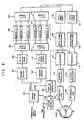
- the interleaving/deinterleaving apparatus for a digital VCRcomprises a formatter 100 for performing the recording format with respect to an input digital data stream in accordance with an ID information and an overhead information, a memory mapper and decoder 200 for keeping the continuity between the segments and performing interleaving with respect to the output of formatter 10 in accordance with the characteristics of the VCR and dividing the data stream, buffering section 300 for buffering the outputs from memory mapper and decoder 200, delay section 400 for successively delaying the data buffered from buffering section 300 for a predetermined time, encoder 500 for encoding the data delayed by delay section 400, inter-symbol interleaver 600 for performing inter-symbol interleaving with respect to the output of encoder 500, inner encoder 700 for performing inner encoding with respect to the interleaved data from inter-symbol interleaver 600, channel coder 800 for connecting the data stream to tape channel, and channel decoder
- formatter 100receives a digital data stream and performs VCR recording format with respect to the respective data segment lines (compressed data or error correction (E.C.C.)) except for the preceding header portion as shown in FIG. 7A and then provides the formatted data stream to memory mapper and decoder 200.
- Memory mapper and decoder 200performs interleaving with respect to the provided data stream in accordance with the characteristics of the VCR, keeping the continuity between the segments.
- the interleaved datapass through respective buffers B1 to Bn in buffering section 300 and respective delays D1, to Dn in delay section 400 and then are constructed as shown in FIG. 7B.
- channel coder 800records the data provided from inner encoder 700 to the tape by connecting the channel of the data stream to that of the tape, thereby completing the interleaving process.
- channel decoder 900decodes the reproduced data and detects and corrects the errors. Thereafter, the detected data are performed by the aforementioned interleaving process reversely, i.e., performed by deinterleaving process.
- the interleaving regionis determined in accordance with the predetermined maximum speed.
- the segments in the neighboring areas within the determined regionare successively formatted as shown in FIG. 7A, 7B and 7C. Accordingly, discontinuity between segments does not occur and thus the interleaving effect is not reduced at any speed lower than maximum speed though the head of VCR may have nonlinear traces.
- FIG. 8shows still another embodiment of the interleaving apparatus according to the present invention.
- the apparatuscomprises format divider 101 for dividing an input compressed data stream into a synchronizing signal and data and formatting the divided synchronizing signal and data, memory mapper 102 for reading and storing data segments of the divided data in zigzag form, outer coder 103 for performing outer coding (i.e., Reed-Solomon coding) with respect to the data N1 and K1 stored in memory mapper 102 and providing the data to which an outer code symbol is added, demultiplexer 104 for demultiplexing the segments provided from outer coder 103 and temporarily storing the data segments in n buffers 105 arranged in a vertical direction, multiplexer 106 for multiplexing the data segments from buffers 105 so as to provide the multiplexed data, inner coder 107 for performing inner coding with respect to the data from multiplexer 106 and providing data having an inner code symbol added thereto, inter-symbol interleaver 108 for performing inter-
- the deinterleaving processis performed by the deinterleaving apparatus in which the above interleaving apparatus is reversely constructed as shown in FIG. 9 and the description thereof will be omitted.
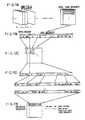
- Format divider 101receives a compressed data stream and divides the data stream into a synchronizing signal and compressed data as shown in FIG. 11A and then performs formatting.
- the divided dataare scanned in zigzag form and stored in the unit of segment in memory mapper 102 as shown in FIG. 11B, being divided into A channel data and B channel data as shown in FIG. 11C so as to be separately processed when the data is read out therefrom.
- Multiplexers 106 and 126multiplex the interleaved data and provide the multiplexed data.
- Inner encoder 107 and 127add the Reed-Solomon code of (N 2 , K 2 ) to the data provided from multiplexers 106 and 126 and perform inner encoding as shown in FIG. 11G so as to provide the encoded data to inter-symbol interleavers 108 and 128.
- Inter-symbol interleavers 108 and 128perform inter-symbol interleaving with respect to the symbol data, thereby correcting the random errors.
- formatters 111 and 131receive a synchronizing signal divided form format divider 101 and a header signal corresponding to the synchronizing signal under the control of system controller 109 and perform formatting with respect to the received data along with the data from inter-symbol interleavers 108 and 128 as shown in FIG. 11H so as to provide the formatted data to channel modulators 112 and 132.
- Channel modulators 112 and 132perform channel modulation with respect to the provided data.
- the modulated dataenter recording amplifiers 113 and 133 to be amplified and then are recorded on the tape.
- FIG. 13shows still another embodiment of the interleaving apparatus according to the present invention.
- the apparatuscomprises a format divider 101 for dividing an input compressed data stream into a synchronizing signal and data and formatting the divided synchronizing signal and the data, memory mapper 102 for reading out and storing in zigzag from the data divided by format divider 101, demultiplexer 104 for dividing the data in a segment stored in memory mapper 102 into n blocks and demultiplexing each segment block and storing the demultiplexed data segment in n buffers 105, multiplexer 106 for multiplexing the data temporarily stored in buffer 105, inter-symbol interleaver 108 for performing interleaving with respect to the symbol data multiplexed through multiplexer 106 in order to divide the symbol data along the same line per block, synchronizing and header signal generator 110 for receiving the synchronizing signal from format divider 101 and providing a header signal corresponding to the synchronizing signal along with the synchronizing signal, a system controller 109 for
- format divider 101enter in two directions so as to divide the data into two channels and the description for only one channel will follow.
- deinterleaving apparatus corresponding to the interleaving apparatusis as shown in FIG. 14 and the construction and operation thereof are simply the reverse of the interleaving apparatus and thus will be omitted.
- Format divider 101divides an input compressed data stream into a synchronizing signal and compressed data and performs formatting as shown in FIG. 18 and thus arranges the compressed data successively per line (i.e., 1 segment).
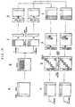
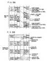
- the data of the divided synchronizing signal and dataare successively written in memory mapper 102 in zigzag form in the unit of segment as shown in FIG. 17A.
- Demultiplexer 104performs demultiplexing with respect to the data stored in memory mapper 102 so as to divide one segment into N blocks as shown in FIG. 7B and writes respective segments for each block to buffer section 105 including N buffers. That is, one segment is written to buffer 1 and the next segment is being shifted for one vertical size so as to be written to buffer 2 as shown in FIG. 17C.
- Multiplexer 106performs multiplexing with respect to the vertically written data and then transmits to inter-symbol interleaver 108 symbols for blocks in the respective segments.
- Inter-symbol interleaver 108performs interleaving to form n blocks by grouping the data in the same position as shown in FIG. 17D, i.e., classifies the data in accordance with line.
- the interleaving process to classify the datais as shown in FIG. 19A, while the conventional process is as shown in FIG. 20A.
- formatter 111receives a synchronizing signal divided from format divider 101 and a header signal corresponding to the synchronizing signal under the control of system controller 109 and performs formatting with respect to the received data along with the data from inter-symbol interleaver 108 as shown in FIG. 17E, so as to provide the formatted data to channel modulator 112.
- Channel modulator 112performs channel modulation with respect to the provided data.
- the modulated dataenter recording amplifiers 113 to be amplified and then are recorded on the tape.
- the incomplete segmentshould be removed as shown in FIG. 20B.
- the incomplete segmentbecomes longer and the orders of data between neighboring segments are changed, thereby connecting the blocks between incomplete segments and increasing the probability of including a slice lying in two segments. Accordingly, the slices extracted from segments can be detected still better, thereby improving the picture quality.
- a recorded/reproduced data segmentis complete or incomplete. If the detected data segment is complete, normal data processing is performed with respect to the complete data segment and ends up when the last segment is processed. If the detected data segment is incomplete, a segment header signal and the end point DSEP and the start point DSSP of the incomplete data are detected.
- the size of the start point of a slice ais compared with that of the end point of the data stream. At this point, if the start point of the slice has a smaller size, a suitable process is performed and ends up when the last segment data is processed. If the size of the start point of the slice is not smaller, it is detected whether the data segment is the last one and the process ends up at that point, which means that no slice is taken.
- the size of the start point of the sliceis compared with that of the data stream. At this time, if the size of the start point of the slice is bigger, a corresponding process is performed until the last data segment is processed. When the last data segment comes out, the process ends up and the start point of the slice which is not bigger will be removed. As a result, the slice extracted from the incomplete data segment can be used for improved picture quality.
- an interleaving/deinterleavingis performed within an interleaving region which is restricted in accordance with a predetermined maximum speed in variable speed play, so that error correction capability is improved though the VCR head may have a nonlinear trace. Error correction capability may also be improved when the error decoding array has insufficient data in high speed play. Furthermore, many slices can enter an incomplete data segment easily, thereby providing picture quality of high resolution.
Landscapes
- Engineering & Computer Science (AREA)
- Multimedia (AREA)
- Signal Processing (AREA)
- Signal Processing For Digital Recording And Reproducing (AREA)
- Error Detection And Correction (AREA)
- Television Signal Processing For Recording (AREA)
- Facsimile Scanning Arrangements (AREA)
- Compression Or Coding Systems Of Tv Signals (AREA)
Description
- The present invention relates to a digital video cassetterecorder (VCR), and more particularly to an apparatus for and amethod of interleaving/deinterleaving for a digital VCR which caneffectively correct errors occurring in recording or reproductionof compressed data and improve error correction capability,especially in variable speed reproduction.
- The errors occurring in recording and reproduction with adigital VCR may be classified as random errors and burst errors.Random errors independently occur in digital signal lines due toadditive noise during signal processing, and burst error issuccessive error occurring with respect to a bit stream oftransmission data under the influence of tape condition, and soon. Burst error can be corrected by being replaced with randomerrors through an interleaving/deinterleaving process.
- A conventional interleaving apparatus for a digital VCR, asshown in FIG. 1, includes
outer coder 1 for performing outercoding with respect to an input compressed data stream andsuccessively outputting the data stream with an outer code symboladded thereto, firstsector array memory 2 for successivelystoring the data outputted fromouter coder 1, andinner coder 3for reading the data stored in firstsector array memory 2 in anorder different from that in storing the data to firstsector array memory 2, performing inner coding, outputting and recordingthe data with inner code symbol added thereto on a tape via ahead. The interleaving apparatus is also provided withinnerdecoder 4 for decoding only data having the inner code symbolamong the data reproduced from the tape, detecting errors in thedata and performing interleaving with respect to such detectederrors, secondsector array memory 5 for distributively storingthe interleaved data frominner decoder 4, andouter decoder 6for reading out data from secondsector array memory 5 in anorder different from that in writing the data and performingdecoding with respect to data having the outer code symbol tocorrect the errors. - In the conventional interleaving apparatus constructed asabove, when the compressed data stream as shown in FIG. 2A isinputted,
outer coder 1 performs outer coding in a verticaldirection with respect to a series of symbols of the input dataas shown in FIG. 2B and outputs data having the outer codesymbol. Then, a redundancy is added to the data having theouter code symbol as shown in FIG. 2C and the redundancy-addeddata is stored in firstsector array memory 2 in the order shownin FIG. 2D. Inner coder 3 reads out the data from firstsector arraymemory 2 in an order different from that in storing the data andperforms interleaving to add the inner code symbol to the data.Accordingly, the order of the data is changed, being differentfrom that of the input data, causing a burst error to be replacedby random errors. The data stream interleaved as describedabove is then inner-coded byinner coder 3, with the result that strong error correction coding (ECC) is performed.Inner decoder 4 decodes the data having the inner codesymbol among the data having the inner and outer code symbolsreproduced from the tape and detects and corrects the errors.That is, in correcting the errors,inner decoder 4 performsinterleaving with respect to the errors which exist beyond itscapability and distributively stores the interleaved data stillhaving errors in secondsector array memory 5.Outer decoder 6performs outer decoding with respect to the data stored in secondsector array memory 5 to correct the remaining errors, andthereby various kinds of errors occurring in reproduction in adigital VCR can be corrected and prevented.- The conventional apparatus as described above thus providesa strong capability to correct various errors occurring inreproduction of data and is suitable for use in a digital VCR forprofessional purposes.
- However, in a home digital VCR, such an elaborate apparatusfor strong error correction cannot be used due to a limitation ofrecording frequency bandwidth and high costs.
- Also, in high speed play such as a picture search mode, theVCR head, as shown in FIGs. 4A to 4C, passes across various tapetracks and the head trace region in a track, as well as the sizeof a sector array memory in the conventional apparatus, isinversely proportional to the degree of high speed.
- Practically, the VCR head in high speed play has a nonlineartrace as shown in FIG. 4C, and this causes the maximuminterleaving region for ECC to be further restricted incomparison to the linear head trace. Also, in high speed play, the head continually passes the track portion of the sameposition due to the restricted interleaving region, and the imagedata of the same picture portion is extracted. Accordingly, inorder to obtain the image data of other picture portions, dataallocation for rearranging the data recording position isrequired.
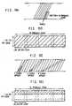
- Further, when a signal is recorded on a tape track by theconventional apparatus as shown in FIG. 10A, a redundancy isadded to the signal, utilizing a two-dimensional Reed-Solomoncode for correcting various kinds of burst and random errors.Thus, in normal reproduction of the signal, the decoding array isfully occupied with information data and the 2-dimensional Reed-Solomondecoding can be performed.
- However, in a special reproduction such as a high speedplay, only a portion of the track can be traced, and thus thedecoding array is partially occupied with information data andonly one-dimensional error decoding can be used, causing theconfidence in correcting the errors to deteriorate.
- Meanwhile, the data segments reproduced by the conventionalapparatus are classified into complete segments and incompletesegments, and the data segment is composed of slices which arethe variable unit in which the image data and other informationare compressed and compacted. Accordingly, as shown in FIG. 15,several slices may exist in the K-th segment while a slice mayexist over two segments as shown in (k + 1)-th segment.
- Such slices may be performed with variable length coding(VLC) or compressed at different rates in encoding a high qualityimage or a normal image. Thus, the lengths of the respective compressed data streams may appear to be different from oneanother, even though the respective image information of the sameamount are compressed. Accordingly, in order to perfectlyperform the variable length decoding (VLD) in a decoder, acomplete bit stream should be reproduced in the unit of slice.
- According to the conventional apparatus, however, groups ofcomplete and incomplete segments are placed in the detected areaas shown in FIG. 16 when the reproduced data stream has beendeinterleaved in variable speed play. If the slices, being theunit of data compaction, exist over incomplete segments excludingthe group of complete segments, such slices in the incompletesegments will be of no use, inviting data loss.
- EP-A-0 508 602 discloses a video-audio digital recordingapparatus comprising an analog/digital converter forconverting analog signals to digital signals when recordingdata on a cassette tape; interleave RAM for storing a blockedvideo signal in a unit of a block; high-efficiency encodingcircuit for compressing the video signal which is read outfrom the interleave RAM and randomly performing the process ofreading the video signal from the interleave RAM; and videoerror collection encoder for encoding the compressed videosignal outputted from the high-efficiency encoding circuit forerror correction. For placing data recorded on a cassettetape, the apparatus comprises deinterleaving elements operatedto the opposite effect. The interleave RAM interleaves adigital video signal of one block comprising a plurality ofpixels outputted from audio-video converter only once in aunit of block. The process of interleaving/deinterleaving thecompressed data is performed irrespective of the regionalspace.
- It is an object of the present invention to provide aninterleaving/deinterleaving apparatus for a digital VCR and themethod thereof which can effectively correct various kinds ofburst and random errors in recording/reproduction of compresseddata.
- It is another object of the present invention to provide aninterleaving/deinterleaving apparatus for a digital VCR and themethod thereof which makes it possible to effect maximuminterleaving/deinterleaving within a predetermined high speed bydetermining an interleaving/deinterleaving region in accordancewith the predetermined high speed and by performinginterleaving/deinterleaving within the determinedinterleaving/deinterleaving region.
- In order to achieve the above objects, there is provided an interleaving/deinterleaving apparatus for a digital VCRaccording to the independent claims. Preferred embodiments of the inventionare claimed in the dependent claims.
- Briefly the apparatus comprises :
- interleaving/deinterleaving control means for restrictivelydetermining an interleaving/deinterleaving region in accordancewith a predetermined maximum speed in recording/reproduction ofcompressed image data;
- memory means for storing and reading out said compressedimage data in a specific format under the control of saidinterleaving/deinterleaving control means; and
- means for performing interleaving/deinterleaving withrespect to said compressed image data provided from said memorymeans.
- Also, in order to achieve the above objects, there isprovided an interleaving/deinterleaving method for a digital VCRaccording to the independent method claims. The methodcomprises the steps of:
- dividing an input compressed data stream into asynchronizing signal and data and formatting the data in the unitof segment;
- reading the formatted data segments in zigzag form andstoring the read data segments in a memory mapper;
- dividing each of the data segments stored in the memorymapper into n segment blocks and successively writing the segmentblocks in a data field with shifting each of the segment blocksfor one vertical size of the data segment; and
- performing inter-symbol interleaving with respect to datasymbols in the segment blocks by classifying the data symbols andsectioning the classified data symbols in line.
- The above objects and other advantages of the presentinvention will become more apparent by describing the preferredembodiments thereof with reference to the accompanying drawings,in which:
- FIG. 1 is a block diagram of the conventional interleavingapparatus for a digital VCR.
- FIGs. 2A to 2D are views explaining the interleavingoperation by means of the apparatus of FIG. 1.
- FIG. 3 is a block diagram of an embodiment of theinterleaving/deinterleaving apparatus according to the presentinvention.
- FIGs. 4A to 4C show the respective states of head trace ontape, track contact area and non-linear track trace in a highspeed search mode.
- FIGs. 5A to 5C are views explaining the interleavingoperation by means of the apparatus of FIG. 3.
- FIG. 6 is a block diagram of another embodiment of theinterleaving/deinterleaving apparatus according to the presentinvention.
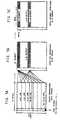
- FIGs. 7A to 7C show the respective states of a recordingdata format of a digital VCR, an interleaving process andinterleaved data.
- FIG. 8 is a block diagram of still another embodiment of theinterleaving apparatus according to the present invention.
- FIG. 9 is a block diagram of still another embodiment of thedeinterleaving apparatus according to the present invention.
- FIG. 10A illustrates the state of a tape track traced innormal play.
- FIG. 10B is a view explaining a decoding array occupied infull by information data.
- FIG. 10C illustrates the state of a tape track traced invariable speed play.
- FIG. 10D is a view explaining a decoding array partiallyoccupied by information data.
- FIG. 11 is a view explaining a data formatting process inrecording in accordance with the present invention.
- FIG. 12 illustrates the state of channel partition resultingform zigzag scanning of the compressed data in the dataformatting process in FIG. 12.
- FIG. 13 is a block diagram of still another embodiment ofthe interleaving apparatus according to the present invention.
- FIG. 14 is a block diagram of still another embodiment ofthe deinterleaving apparatus according to the present invention.
- FIG. 15 is a view explaining the structure of a sliceexisting in the compressed data.
- FIG. 16 shows an example of groups of complete andincomplete segments in a detected area.
- FIGs. 17A to 17E are views explaining a data formattingprocess in data recording/reproduction in accordance with thepresent invention.
- FIG. 18 is a view explaining a synchronizing signal and datadivided from the compressed data stream by the apparatus of FIG. 13.
- FIGs. 19A and 19B show the data formate arranged ininterleaving and deinterleaving according to the presentinvention.
- FIGs. 20A and 20B show the data formats rearranged ininterleaving and deinterleaving according to the conventionalapparatus.
- FIG. 21 is an algorithm diagram incorporating theinterleaving/deinterleaving method according to the presentinvention.
- FIG. 3 shows an embodiment of the interleaving/deinterleavingapparatus for a digital VCR according to thepresent invention. The apparatus comprises
source encoder 10for encoding an input image data stream,memory mapper 20 forstoring and reading out the image data stream encoded bysourceencoder 10 in the unit of segment, interleavingcontroller 30 forrestricting an interleaving region in accordance with a headerinformation in line with a predetermined maximum speed,inter-segmentinterleaver 40 for performing inter-segment interleavingwith respect to segments of the image data stream provided frommemory mapper 20,outer encoder 50 for performing outer encodingwith respect to the image data stream frominter-segmentinterleaver 40,intra-segment interleaver 60 for performingintra-segment interleaving with respect to the segments of theimage data stream fromouter encoder 50, andinner encoder 70 forperforming inner encoding with respect to the image data streamfromintra-segment interleaver 60. - A video head may pass through many more tracks as shown inFIG. 4A in high speed play such as in picture search mode than innormal speed play as shown in FIG. 4B and thus substantially much data in the track cannot be read out. Accordingly, errors occurand propagate due to the unread data so that even a powerful ECCmay not function.
- Thus, the maximum interleaving region should be smaller thanthe area of the track trace covered by the head in the maximumspeed mode of the VCR, wherein the region is obtained by thefollowing expression
- In this embodiment, after
source encoder 10 encodes an inputdigital data stream and provides the data stream as shown in FIG.5A,memory mapper 20 divides the data stream in the unit ofsegment as shown in FIG. 5B and stores the divided data stream.At this time, interleavingcontroller 30 provides to memorymapper 20 a control signal for determining an interleaving regionin accordance with a VCR status signal and ID information in linewith the above expression and performing interleaving within thedetermined region, thereby preventing the reduction ofinterleaving effect in normal and high speed reproduction. - At this point, TD shows a track deviation degree of thehead. If TD=1, the center of the head is in accord with that ofthe track and thus tracking is completely performed. If TD < 1,the track is deviating from the head. That is, in variablespeed play, the head passes through many tracks so that theregion in which a head can read information data for one track should be within the range of 0 ≤
TD ≤ 1. Inter-segment interleaver 40 performs inter-segmentinterleaving and provides the interleaved data toouter encoder 50, where the inter-segment interleaving can be achieved byinterleaving data between segments in the process of reading outdata frommemory mapper 20 in the unit of segment.Outerencoder 50 performs outer encoding with respect to the data frominter-segment interleaver 40 and provides the encoded data tointra-segment interleaver 60.Intra-segment interleaver 60performs intra-segment interleaving, i.e., interleaves datainside of segments as shown in FIG. 5C. Thus, burst errors inthe data stream can be replaced by random errors and the datafromintra-segment interleaver 60 are ECC-processed byinnerencoder 70 and then written to the tape through the head.- Referring to FIG. 6, the interleaving/deinterleavingapparatus for a digital VCR according to another embodiment ofthe invention comprises a
formatter 100 for performing therecording format with respect to an input digital data stream inaccordance with an ID information and an overhead information, amemory mapper anddecoder 200 for keeping the continuity betweenthe segments and performing interleaving with respect to theoutput offormatter 10 in accordance with the characteristics ofthe VCR and dividing the data stream,buffering section 300 forbuffering the outputs from memory mapper anddecoder 200,delaysection 400 for successively delaying the data buffered frombuffering section 300 for a predetermined time,encoder 500 forencoding the data delayed bydelay section 400,inter-symbolinterleaver 600 for performing inter-symbol interleaving with respect to the output ofencoder 500,inner encoder 700 forperforming inner encoding with respect to the interleaved datafrominter-symbol interleaver 600,channel coder 800 forconnecting the data stream to tape channel, andchannel decoder 900 for decoding the data reproduced from the tape. - In the above embodiment,
formatter 100 receives a digitaldata stream and performs VCR recording format with respect to therespective data segment lines (compressed data or errorcorrection (E.C.C.)) except for the preceding header portion asshown in FIG. 7A and then provides the formatted data stream tomemory mapper anddecoder 200. Memory mapper anddecoder 200performs interleaving with respect to the provided data stream inaccordance with the characteristics of the VCR, keeping thecontinuity between the segments. The interleaved data passthrough respective buffers B1 to Bn inbuffering section 300 andrespective delays D1, to Dn indelay section 400 and then areconstructed as shown in FIG. 7B. - When the interleaved data are encoded through
encoder 500and applied tointer-symbol interleaver 600, the data areshuffled completely as shown in FIG. 7C and are inner-encoded byinner encoder 700 so as to be provided tochannel coder 800.Channel coder 800 records the data provided frominner encoder 700 to the tape by connecting the channel of the data stream tothat of the tape, thereby completing the interleaving process. - When the data recorded on the tape are made o bereproduced,
channel decoder 900 decodes the reproduced data anddetects and corrects the errors. Thereafter, the detected dataare performed by the aforementioned interleaving process reversely, i.e., performed by deinterleaving process. - In variable speed reproduction play, the interleaving regionis determined in accordance with the predetermined maximum speed.The segments in the neighboring areas within the determinedregion are successively formatted as shown in FIG. 7A, 7B and 7C.Accordingly, discontinuity between segments does not occur andthus the interleaving effect is not reduced at any speed lowerthan maximum speed though the head of VCR may have nonlineartraces.
- FIG. 8 shows still another embodiment of the interleavingapparatus according to the present invention. The apparatuscomprises format divider 101 for dividing an input compresseddata stream into a synchronizing signal and data and formattingthe divided synchronizing signal and data, memory mapper 102 forreading and storing data segments of the divided data in zigzagform, outer coder 103 for performing outer coding (i.e., Reed-Solomoncoding) with respect to the data N1 and K1 stored inmemory mapper 102 and providing the data to which an outer codesymbol is added, demultiplexer 104 for demultiplexing thesegments provided from outer coder 103 and temporarily storingthe data segments in n buffers 105 arranged in a verticaldirection, multiplexer 106 for multiplexing the data segmentsfrom buffers 105 so as to provide the multiplexed data, innercoder 107 for performing inner coding with respect to the datafrom multiplexer 106 and providing data having an inner codesymbol added thereto, inter-symbol interleaver 108 for performinginter-symbol interleaving with respect to the data provided frominner encoder 107, synchronizing and header signal generator 110 for receiving the synchronizing signal from format divider 101and providing a header signal corresponding to the synchronizingsignal along with the synchronizing signal, system controller 109for controlling format divider 101 and synchronizing and headersignal generator 110 in accordance with an input TBM signal,formatter 111 for formatting the synchronizing and the headersignals form synchronizing and header signal generator 110 andthe symbol code data from inter-symbol interleaver 108, channelmodulator 112 for modulating the data from formatter 111 andproviding the modulated signal as a tape recording signal, andrecording amplifier 113 for amplifying the data from channelmodulator 112 to make the data have an appropriate level andrecording the amplified data to the tape.
- For the reproduced data, the deinterleaving process isperformed by the deinterleaving apparatus in which the aboveinterleaving apparatus is reversely constructed as shown in FIG.9 and the description thereof will be omitted.
- Meanwhile, it will be understood that the data divided by
format divider 101 enter in two directions so as to be dividedinto two channels and the description for only one channel willfollow. Format divider 101 receives a compressed data stream anddivides the data stream into a synchronizing signal andcompressed data as shown in FIG. 11A and then performsformatting. The divided data are scanned in zigzag form andstored in the unit of segment inmemory mapper 102 as shown inFIG. 11B, being divided into A channel data and B channel data asshown in FIG. 11C so as to be separately processed when the data is read out therefrom.Multiplexers Inner encoder multiplexers inter-symbolinterleavers Inter-symbol interleavers - Thus, from synchronizing and
header signal generator 110,formatters form format divider 101 and a header signal corresponding to thesynchronizing signal under the control ofsystem controller 109and perform formatting with respect to the received data alongwith the data frominter-symbol interleavers modulators Channel modulators recording amplifiers - In reproduction, errors can be prevented by reverselyreproducing the data formatted and recorded as described above byway of the circuit of FIG. 9.
- FIG. 13 shows still another embodiment of the interleavingapparatus according to the present invention. The apparatuscomprises a format divider 101 for dividing an input compresseddata stream into a synchronizing signal and data and formattingthe divided synchronizing signal and the data, memory mapper 102 for reading out and storing in zigzag from the data divided byformat divider 101, demultiplexer 104 for dividing the data in asegment stored in memory mapper 102 into n blocks anddemultiplexing each segment block and storing the demultiplexeddata segment in n buffers 105, multiplexer 106 for multiplexingthe data temporarily stored in buffer 105, inter-symbolinterleaver 108 for performing interleaving with respect to thesymbol data multiplexed through multiplexer 106 in order todivide the symbol data along the same line per block,synchronizing and header signal generator 110 for receiving thesynchronizing signal from format divider 101 and providing aheader signal corresponding to the synchronizing signal alongwith the synchronizing signal, a system controller 109 forcontrolling format divider 104 and synchronizing and headersignal generator 110 in accordance with an input TBM signal,formatter 111 for formatting the synchronizing and the headersignals from synchronizing and header signal generator 110 andthe symbol data from inter-symbol interleaver 108, channelmodulator 112 for modulating the data from formatter 111 so as tomake the modulated data suitable for recording on the tape, andrecording amplifier 113 for amplifying the data from channelmodulator 112 up to an appropriate level and recording theamplified data to the tape.
- It will be understood that the data divided by
formatdivider 101 enter in two directions so as to divide the data intotwo channels and the description for only one channel willfollow. - In addition, the deinterleaving apparatus corresponding to the interleaving apparatus is as shown in FIG. 14 and theconstruction and operation thereof are simply the reverse of theinterleaving apparatus and thus will be omitted.
Format divider 101 divides an input compressed data streaminto a synchronizing signal and compressed data and performsformatting as shown in FIG. 18 and thus arranges the compresseddata successively per line (i.e., 1 segment). The data of thedivided synchronizing signal and data are successively written inmemory mapper 102 in zigzag form in the unit of segment as shownin FIG. 17A.Demultiplexer 104 performs demultiplexing with respect tothe data stored inmemory mapper 102 so as to divide one segmentinto N blocks as shown in FIG. 7B and writes respective segmentsfor each block to buffersection 105 including N buffers. Thatis, one segment is written to buffer 1 and the next segment isbeing shifted for one vertical size so as to be written to buffer2 as shown in FIG. 17C.Multiplexer 106 performs multiplexing with respect to thevertically written data and then transmits tointer-symbolinterleaver 108 symbols for blocks in the respective segments.Inter-symbol interleaver 108 performs interleaving to form nblocks by grouping the data in the same position as shown in FIG. 17D,i.e., classifies the data in accordance with line. Theinterleaving process to classify the data is as shown in FIG.19A, while the conventional process is as shown in FIG. 20A.- Thus, from synchronizing and
header signal generator 110,formatter 111 receives a synchronizing signal divided fromformatdivider 101 and a header signal corresponding to the synchronizing signal under the control ofsystem controller 109and performs formatting with respect to the received data alongwith the data frominter-symbol interleaver 108 as shown in FIG.17E, so as to provide the formatted data to channelmodulator 112.Channel modulator 112 performs channel modulation withrespect to the provided data. The modulated data enterrecording amplifiers 113 to be amplified and then are recorded onthe tape. - In the conventional method, after the deinterleaving processis completed by performing interleaving in opposite by way of theapparatus of FIG. 14, the incomplete segment should be removed asshown in FIG. 20B. However, according to the present invention,as shown in FIG. 19B, the incomplete segment becomes longer andthe orders of data between neighboring segments are changed,thereby connecting the blocks between incomplete segments andincreasing the probability of including a slice lying in twosegments. Accordingly, the slices extracted from segments canbe detected still better, thereby improving the picture quality.
- The process of extracting slices from incomplete segments tomake them useful will be explained with reference to FIG. 21.
- First, after interleaving/deinterleaving is performed, it isdetected whether a recorded/reproduced data segment is completeor incomplete. If the detected data segment is complete, normaldata processing is performed with respect to the complete datasegment and ends up when the last segment is processed.Ifthe detected data segment is incomplete, a segment header signaland the end point DSEP and the start point DSSP of the incompletedata are detected.
- If the start point of the data stream does not exist, thesize of the start point of a slice a is compared with that of theend point of the data stream. At this point, if the start pointof the slice has a smaller size, a suitable process is performedand ends up when the last segment data is processed. If thesize of the start point of the slice is not smaller, it isdetected whether the data segment is the last one and the processends up at that point, which means that no slice is taken.
- Meanwhile, if the start point of the incomplete data streamexists, the size of the start point of the slice is compared withthat of the data stream. At this time, if the size of the startpoint of the slice is bigger, a corresponding process isperformed until the last data segment is processed. When thelast data segment comes out, the process ends up and the startpoint of the slice which is not bigger will be removed. As aresult, the slice extracted from the incomplete data segment canbe used for improved picture quality.
- From the foregoing, it will be apparent that according tothe present invention, an interleaving/deinterleaving isperformed within an interleaving region which is restricted inaccordance with a predetermined maximum speed in variable speedplay, so that error correction capability is improved though theVCR head may have a nonlinear trace. Error correctioncapability may also be improved when the error decoding array hasinsufficient data in high speed play. Furthermore, many slicescan enter an incomplete data segment easily, thereby providingpicture quality of high resolution.
Claims (15)
- An interleaving/deinterleaving apparatus for adigital video cassette recorder comprising:interleaving/deinterleaving control means (30) for determininga restrictive interleaving/deinterleaving region which is smallerthan the region covering a track in a maximum speed in recordingand reproducing of compressed image data;memory means (20) for storing and reading out said compressedimage data in an unit of a segment under the control of saidinterleaving/deinterleaving control means; andmeans (40, 60) for performing an inter-segment and intra-segmentinterleaving/deinterleaving with respect to saidcompressed image data provided from said memory means;the said means carrying out the interleaving function duringrecording compressed image data and the deinterleaving functionduring playing recorded compressed image data, deinterleaving being opposite to interleaving and the deinterleaving portion of said meansbeing interconnected in the reverse sequence than the interleaving portion of said means.
- The interleaving/deinterleaving apparatus for adigital video cassette recorder according to claim 1 comprising:for the interlaving function :a source encoder (10) for encoding an input image data stream;the interleaving controller (30) providing a control signalfor restricting the interleaving region in accordance with headerinformation in line with the predetermined maximum speed;the memory mapper (20) storing and reading out in the unitof segment said image data stream encoded by said source encoderin accordance with said control signal from said interleavingcontroller (30);the inter-segment interleaver (40) performing inter-segmentinterleaving with respect to segments of said image data streamprovided from said memory mapper (20); andthe intra-segment interleaver (60) performing intra-segment interleaving with respect to said segments of said image datastream from said inter-segment interleaver (40); andfor the deinterleaving function : corresponding elements operated to the opposite effect, and interconnected in the reverse sequence.
- An interleaving/deinterleaving apparatus as claimedin claim 2, wherein said interleaving region restrictivelydetermined by said interleaving controller (30) is obtained by thefollowing expression
- An interleaving/deinterleaving apparatus as claimedin claim 2, further comprising:an outer encoder (50), connected between said inter-segmentinterleaver (40) and said intra-segment interleaver (60), forperforming outer encoding with respect to said image data streamfrom said inter-segment interleaver (40); andan inner encoder (70) for performing inner encoding withrespect to said image data stream from said intra-segmentinterleaver (60) and providing said inner-encoded image data streamas a tape recording signal.
- An interleaving/deinterleaving apparatus for adigital video cassette recorder comprising:for the interleaving function :a formatter (100) for dividing an input image data stream intoa synchronizing signal and image data;a memory mapper (200) for storing and reading out said imagedata stream from said formatter (100) in accordance withidentification information for each data segment of said imagedata;a decoder (200) for decoding said image data stream from saidmemory mapper (200) in accordance with the identificationinformation of said data segment and providing the decoded imagedata stream;buffering and delay means (300, 400) for performinginterleaving, keeping the continuity between said data segmentsby buffering said image data stream from said decoder 200 andsuccessively delaying the buffered image data stream for apredetermined time;a first encoder (500) for encoding the output of said bufferingand delay means (300, 400) and providing the successivelyinterleaved image data stream;an inter-symbol interleaver (600) for performing inter-symbolinterleaving with respect to the interleaved data segment fromsaid first encoder (500);a second encoder (700) for adding said identificationinformation of said data segment and overhead information to saidsynchronizing signal from said formatter (100); anda channel coder (800) for receiving the outputs of said inter-symbolinterleaver(600) and said second encoder (700), reconstructinga complete data segment and channel-modulating the reconstructeddata segment to provide the channel-modulated data segment as atape recording signal;and for the deinterleaving function :corresponding elements operated to the opposite effect and interconnected in the reverse sequence.
- An interleaving/deinterleaving apparatus as claimedin claim 5, further comprising:an inner coder (700), connected between said inter-symbolinterleaver (600) and said channel coder (800), for performing innercoding with respect to said image data interleaved by said inter-symbol interleaver 600.
- An interleaving/deinterleaving apparatus for adigital video cassette recorder comprising:for the interleaving function :a format divider (101) for dividing an input compressed datastream into a synchronizing signal and data and formatting thedivided synchronizing signal and data;a memory mapper (102, 112) for reading out and storing datasegments of said divided data in zigzag form;a demultiplexer (104, 124) for demultiplexing said datasegments provided from said memory mapper 102, 122 and temporarilystoring said data segments in a plurality of buffers 105, 125;a multiplexer (106, 126) for multiplexing said data segmentsfrom said buffers (105, 125) and providing the multiplexed data;an inter-symbol interleaver (108, 128) for performing inter-symbolinterleaving with respect to said data provided from saidmultiplexer (106, 126);a synchronizing and header signal generator (110) for receivingsaid synchronizing signal from said format divider (101) andproviding a header signal corresponding to said synchronizingsignal along with said synchronizing signal;a system controller (109) for controlling said format divider(101) and said synchronizing and header signal generator (110) inaccordance with an input TBM signal;a formatter (111, 131) for formatting said synchronizing andsaid header signals from said synchronizing and header signalgenerator (110) and said symbol data from said inter-symbolinterleaver (108, 128); anda channel modulator (112, 132) for modulating said data form said formatter (111, 131) and providing the modulated data as a taperecording signal; andfor the deinterleaving function :corresponding elements operated to the opposite effect and interconnected in the reverse sequence.
- An interleaving/deinterleaving apparatus as claimedin claim 7, further comprising:an outer coder (103, 123), connected between said memory mapper(102, 122) and said demultiplexer (104, 124) for performing outercoding with respect to said data from said memory mapper (102, 122)and providing said data with adding an outer code thereto; andan inner coder (107, 127) connected between said multiplexer106, 126 and said inter-symbol interleaver (108, 128) for codingsaid data from said multiplexer (106, 126) end providing said datawith adding an inner code there to.
- An interleaving/deinterleaving apparatus as claimedin claim 7, wherein said format divider (101) selects said data persymbol or per block and dividing said selected data into aplurality of data channels.
- An interleaving/deinterleaving apparatus as claimedin claim 7, wherein said format divider (101) scans said data perline in zigzag form and dividing said scanned data into aplurality of data channels.
- An interleaving/deinterleaving apparatus as claimedin claim 7, wherein said demultiplexer (106, 126) performs line-shiftingwith respect to said data segments so that said each datasegment has a delay time different from one another and storingsaid shifted data segments in said plurality of buffers (105, 125)whereby an interleaving effect is not degraded in variable speedplay.
- An interleaving/deinterleaving method for a digitalvideo cassette recorder comprising the steps of:for the interleaving function of the method :dividing an input compressed data stream into asynchronizing signal and data and formatting the data in the unitof segment;reading the formatted data segments in zigzag form andstoring the read data segments in a memory mapper;dividing each of the data segments stored in the memorymapper into n segment blocks and successively and verticallywriting the segment blocks in a data field with shifting each ofthe segment blocks for one vertical size of the data segment; andperforming inter-symbol interleaving with respect to datasymbols in the segment blocks by classifying the data symbols andsectioning the classified data symbols in line; andfor the deinterleaving function of the method :carrying out corresponding steps of opposite effect in a reverse sequence.
- An interleaving/deinterleaving method as claimed inclaim 12, wherein the formatting step includes a substep ofdividing the data segments into a plurality of data channels.
- An interleaving/deinterleaving method as claimed inclaim 12, herein each of the data segments is divided into aplurality of blocks at the dividing and shifting step whereby asmall burst error in the data segment is prevented.
- An interleaving/deinterleaving method for a digitalvideo cassette recorder comprising the steps of:for the interleaving function of the method :detecting whether a recorded/reproduced data segment iscomplete or incomplete;performing normal data processing if the detected datasegment is complete and ending up with the last data segment;detecting a segment header signal and start and end pointsof the incomplete data stream if the detected data segment isincomplete and checking if the start point of the incomplete datastream exists;comparing the size of the start point of a slice and the endpoint of the data stream if the start point of the data streamdoes not exist;extracting the slice from the incomplete data segment if thestart point of the slice is smaller than the end point of thedata stream, and performing the segment detecting step if thestart point of the slice is not smaller;comparing the size of the start point of the slice and thestart point of the data stream if the end point of the datastream exists at the slice extracting step; andextracting the slice from the incomplete data segment if thestart point of the slice is bigger than the start point of thedata stream, and performing the segment detecting step if thestart point of the slice is not bigger ; andfor the deinterleaving function of the method :carrying out corresponding steps with opposite effectin a reversed sequence.
Applications Claiming Priority (8)
| Application Number | Priority Date | Filing Date | Title |
|---|---|---|---|
| KR9220834 | 1992-11-06 | ||
| KR1019920020834AKR950003626B1 (en) | 1992-11-06 | 1992-11-06 | Interleaving system of digital vcr |
| KR1019930002115AKR950009673B1 (en) | 1993-02-16 | 1993-02-16 | Digital V Interleaving and Deinterleaving Unit |
| KR932115 | 1993-02-16 | ||
| KR9310117 | 1993-06-04 | ||
| KR9310116 | 1993-06-04 | ||
| KR1019930010117AKR970000918B1 (en) | 1993-06-04 | 1993-06-04 | Formatting and Slice Extraction Method for Interleaving / Deinterleaving |
| KR1019930010116AKR950008643B1 (en) | 1993-06-04 | 1993-06-04 | Digital VLC's Error Compensator |
Publications (3)
| Publication Number | Publication Date |
|---|---|
| EP0596826A2 EP0596826A2 (en) | 1994-05-11 |
| EP0596826A3 EP0596826A3 (en) | 1994-11-30 |
| EP0596826B1true EP0596826B1 (en) | 1999-04-28 |
Family
ID=27482961
Family Applications (1)
| Application Number | Title | Priority Date | Filing Date |
|---|---|---|---|
| EP93630083AExpired - LifetimeEP0596826B1 (en) | 1992-11-06 | 1993-11-04 | Shuffling method for a digital videotape recorder |
Country Status (4)
| Country | Link |
|---|---|
| US (1) | US5581361A (en) |
| EP (1) | EP0596826B1 (en) |
| JP (1) | JP2931747B2 (en) |
| DE (2) | DE69324650T2 (en) |
Cited By (54)
| Publication number | Priority date | Publication date | Assignee | Title |
|---|---|---|---|---|
| US6170074B1 (en) | 1999-02-12 | 2001-01-02 | Sony Corporation | Source coding to provide for robust error recovery |
| US6263468B1 (en) | 1997-10-23 | 2001-07-17 | Sony Corporation | Apparatus and method for partial buffering transmitted data to provide robust error recovery in a lossy transmission environment |
| US6307560B1 (en) | 1999-02-12 | 2001-10-23 | Sony Corporation | Classified adaptive spatio-temporal format conversion method and apparatus |
| US6307979B1 (en) | 1999-02-12 | 2001-10-23 | Sony Corporation | Classified adaptive error recovery method and apparatus |
| US6351494B1 (en) | 1999-09-24 | 2002-02-26 | Sony Corporation | Classified adaptive error recovery method and apparatus |
| US6389562B1 (en) | 1999-06-29 | 2002-05-14 | Sony Corporation | Source code shuffling to provide for robust error recovery |
| US6473876B1 (en) | 1999-06-29 | 2002-10-29 | Sony Corporation | Method and apparatus for encoding of bitstreams using rotation |
| US6493842B1 (en) | 1999-06-29 | 2002-12-10 | Sony Corporation | Time-varying randomization for data synchronization and implicit information transmission |
| US6519369B1 (en) | 1999-02-12 | 2003-02-11 | Sony Corporation | Method and apparatus for filter tap expansion |
| US6522785B1 (en) | 1999-09-24 | 2003-02-18 | Sony Corporation | Classified adaptive error recovery method and apparatus |
| US6539517B1 (en) | 1999-11-09 | 2003-03-25 | Sony Corporation | Data transformation for explicit transmission of control information |
| US6549672B1 (en) | 1999-06-29 | 2003-04-15 | Sony Corporation | Method and apparatus for recovery of encoded data using central value |
| US6591398B1 (en) | 1999-02-12 | 2003-07-08 | Sony Corporation | Multiple processing system |
| US6621936B1 (en) | 1999-02-12 | 2003-09-16 | Sony Corporation | Method and apparatus for spatial class reduction |
| US6859493B2 (en) | 1999-02-12 | 2005-02-22 | Sony Corporation | Apparatus and method for the recovery of compression constants in the encoded domain |
| US7010737B2 (en) | 1999-02-12 | 2006-03-07 | Sony Corporation | Method and apparatus for error data recovery |
| US7039938B2 (en) | 2002-01-02 | 2006-05-02 | Sony Corporation | Selective encryption for video on demand |
| US7120250B2 (en) | 2002-09-09 | 2006-10-10 | Sony Corporation | Content distribution for multiple digital rights management |
| US7124303B2 (en) | 2001-06-06 | 2006-10-17 | Sony Corporation | Elementary stream partial encryption |
| US7155012B2 (en) | 2002-01-02 | 2006-12-26 | Sony Corporation | Slice mask and moat pattern partial encryption |
| US7215770B2 (en) | 2002-01-02 | 2007-05-08 | Sony Corporation | System and method for partially encrypted multimedia stream |
| US7218738B2 (en) | 2002-01-02 | 2007-05-15 | Sony Corporation | Encryption and content control in a digital broadcast system |
| US7225164B1 (en) | 2000-02-15 | 2007-05-29 | Sony Corporation | Method and apparatus for implementing revocation in broadcast networks |
| US7233669B2 (en) | 2002-01-02 | 2007-06-19 | Sony Corporation | Selective encryption to enable multiple decryption keys |
| US7263187B2 (en) | 2003-10-31 | 2007-08-28 | Sony Corporation | Batch mode session-based encryption of video on demand content |
| US7286667B1 (en) | 2003-09-15 | 2007-10-23 | Sony Corporation | Decryption system |
| US7292692B2 (en) | 2003-03-25 | 2007-11-06 | Sony Corporation | Content scrambling with minimal impact on legacy devices |
| US7292691B2 (en) | 2002-01-02 | 2007-11-06 | Sony Corporation | Progressive video refresh slice detection |
| US7302058B2 (en) | 1999-03-30 | 2007-11-27 | Sony Corporation | Method and apparatus for securing control words |
| US7302059B2 (en) | 2002-01-02 | 2007-11-27 | Sony Corporation | Star pattern partial encryption |
| US7343013B2 (en) | 2003-12-16 | 2008-03-11 | Sony Corporation | Composite session-based encryption of video on demand content |
| US7346163B2 (en) | 2003-10-31 | 2008-03-18 | Sony Corporation | Dynamic composition of pre-encrypted video on demand content |
| US7350082B2 (en) | 2001-06-06 | 2008-03-25 | Sony Corporation | Upgrading of encryption |
| US7376233B2 (en) | 2002-01-02 | 2008-05-20 | Sony Corporation | Video slice and active region based multiple partial encryption |
| US7409702B2 (en) | 2003-03-20 | 2008-08-05 | Sony Corporation | Auxiliary program association table |
| US7508942B2 (en) | 2002-11-05 | 2009-03-24 | Sony Corporation | Multi-process descrambler |
| US7530084B2 (en) | 2002-05-28 | 2009-05-05 | Sony Corporation | Method and apparatus for synchronizing dynamic graphics |
| US7555464B2 (en) | 2006-03-01 | 2009-06-30 | Sony Corporation | Multiple DRM management |
| US7565546B2 (en) | 1999-03-30 | 2009-07-21 | Sony Corporation | System, method and apparatus for secure digital content transmission |
| US7620180B2 (en) | 2003-11-03 | 2009-11-17 | Sony Corporation | Preparation of content for multiple conditional access methods in video on demand |
| US7702589B2 (en) | 1999-11-09 | 2010-04-20 | Sony Corporation | Method for simulcrypting scrambled data to a plurality of conditional access devices |
| US7730300B2 (en) | 1999-03-30 | 2010-06-01 | Sony Corporation | Method and apparatus for protecting the transfer of data |
| US7747853B2 (en) | 2001-06-06 | 2010-06-29 | Sony Corporation | IP delivery of secure digital content |
| US7765567B2 (en) | 2002-01-02 | 2010-07-27 | Sony Corporation | Content replacement by PID mapping |
| US7823174B2 (en) | 2002-01-02 | 2010-10-26 | Sony Corporation | Macro-block based content replacement by PID mapping |
| US7853980B2 (en) | 2003-10-31 | 2010-12-14 | Sony Corporation | Bi-directional indices for trick mode video-on-demand |
| US7895617B2 (en) | 2004-12-15 | 2011-02-22 | Sony Corporation | Content substitution editor |
| US7895616B2 (en) | 2001-06-06 | 2011-02-22 | Sony Corporation | Reconstitution of program streams split across multiple packet identifiers |
| US8041190B2 (en) | 2004-12-15 | 2011-10-18 | Sony Corporation | System and method for the creation, synchronization and delivery of alternate content |
| US8185921B2 (en) | 2006-02-28 | 2012-05-22 | Sony Corporation | Parental control of displayed content using closed captioning |
| US8572408B2 (en) | 2002-11-05 | 2013-10-29 | Sony Corporation | Digital rights management of a digital device |
| US8645988B2 (en) | 2002-12-13 | 2014-02-04 | Sony Corporation | Content personalization for digital content |
| US8667525B2 (en) | 2002-12-13 | 2014-03-04 | Sony Corporation | Targeted advertisement selection from a digital stream |
| US8818896B2 (en) | 2002-09-09 | 2014-08-26 | Sony Corporation | Selective encryption with coverage encryption |
Families Citing this family (16)
| Publication number | Priority date | Publication date | Assignee | Title |
|---|---|---|---|---|
| EP0618567B1 (en)* | 1993-03-03 | 1999-07-28 | Matsushita Electric Industrial Co., Ltd. | Signal recording and reproducing apparatus |
| JP3568984B2 (en)* | 1994-06-20 | 2004-09-22 | 株式会社日立製作所 | Information reproducing method, reproducing apparatus, output method and output apparatus |
| JP3362146B2 (en)* | 1996-07-03 | 2003-01-07 | 松下電器産業株式会社 | Reproduction device and recording / reproduction device |
| CN1174631C (en)* | 1997-10-23 | 2004-11-03 | 索尼电子有限公司 | Apparatus and method for partial buffering transmitted data to provide robust error recovery in lossy transmission environment |
| US6581170B1 (en)* | 1997-10-23 | 2003-06-17 | Sony Corporation | Source coding to provide for robust error recovery during transmission losses |
| US6192161B1 (en) | 1999-02-12 | 2001-02-20 | Sony Corporation | Method and apparatus for adaptive filter tap selection according to a class |
| US6154761A (en)* | 1999-02-12 | 2000-11-28 | Sony Corporation | Classified adaptive multiple processing system |
| US6535148B1 (en) | 1999-02-12 | 2003-03-18 | Sony Corporation | Method and apparatus for truncated decoding |
| US6151416A (en)* | 1999-02-12 | 2000-11-21 | Sony Corporation | Method and apparatus for adaptive class tap selection according to multiple classification |
| US6178266B1 (en) | 1999-02-12 | 2001-01-23 | Sony Corporation | Method and apparatus for the recovery of compression constants in the encoded domain |
| US7057666B2 (en)* | 2000-10-24 | 2006-06-06 | Harris Corporation | System and method for encoding information into a video signal |
| JP3805614B2 (en)* | 2000-11-01 | 2006-08-02 | 株式会社日立製作所 | Digital signal generation method and recording medium |
| US7613344B2 (en)* | 2003-12-08 | 2009-11-03 | Electronics And Telecommunications Research Institute | System and method for encoding and decoding an image using bitstream map and recording medium thereof |
| US7564874B2 (en) | 2004-09-17 | 2009-07-21 | Uni-Pixel Displays, Inc. | Enhanced bandwidth data encoding method |
| US20070124648A1 (en)* | 2005-10-31 | 2007-05-31 | Ajay Dholakia | Data protection method |
| JP2021044046A (en)* | 2019-09-13 | 2021-03-18 | キオクシア株式会社 | Memory systems, semiconductor integrated circuits, and bridge communication systems |
Family Cites Families (10)
| Publication number | Priority date | Publication date | Assignee | Title |
|---|---|---|---|---|
| JPS59176986A (en)* | 1983-03-26 | 1984-10-06 | Sony Corp | Digital data transmission device |
| JPS60185262A (en)* | 1984-03-02 | 1985-09-20 | Pioneer Electronic Corp | Recording and reproducing system of video format signal |
| DE3685991T2 (en)* | 1985-05-21 | 1993-03-04 | Sony Corp | ARRANGEMENT FOR DECODING AN ERROR CORRECTING CODE. |
| JPH0771250B2 (en)* | 1986-05-20 | 1995-07-31 | ソニー株式会社 | Digital video tape recorder |
| JP2522258B2 (en)* | 1986-09-05 | 1996-08-07 | ソニー株式会社 | Signal processor |
| JP2526875B2 (en)* | 1986-11-05 | 1996-08-21 | ソニー株式会社 | Digital information recorder |
| JPH0828066B2 (en)* | 1988-08-31 | 1996-03-21 | 松下電器産業株式会社 | Playback device |
| US5291282A (en)* | 1990-04-19 | 1994-03-01 | Olympus Optical Co., Ltd. | Image data coding apparatus and method capable of controlling amount of codes |
| JP2548444B2 (en)* | 1990-09-18 | 1996-10-30 | 松下電器産業株式会社 | Recording and playback device |
| JP3141139B2 (en)* | 1991-03-13 | 2001-03-05 | 三菱電機株式会社 | Video / audio digital recording / playback device |
- 1993
- 1993-11-04EPEP93630083Apatent/EP0596826B1/ennot_activeExpired - Lifetime
- 1993-11-04DEDE69324650Tpatent/DE69324650T2/ennot_activeExpired - Fee Related
- 1993-11-04DEDE0596826Tpatent/DE596826T1/enactivePending
- 1993-11-08USUS08/148,498patent/US5581361A/ennot_activeExpired - Fee Related
- 1993-11-08JPJP5302297Apatent/JP2931747B2/ennot_activeExpired - Fee Related
Cited By (69)
| Publication number | Priority date | Publication date | Assignee | Title |
|---|---|---|---|---|
| US6263468B1 (en) | 1997-10-23 | 2001-07-17 | Sony Corporation | Apparatus and method for partial buffering transmitted data to provide robust error recovery in a lossy transmission environment |
| US6859493B2 (en) | 1999-02-12 | 2005-02-22 | Sony Corporation | Apparatus and method for the recovery of compression constants in the encoded domain |
| US6621936B1 (en) | 1999-02-12 | 2003-09-16 | Sony Corporation | Method and apparatus for spatial class reduction |
| US6307979B1 (en) | 1999-02-12 | 2001-10-23 | Sony Corporation | Classified adaptive error recovery method and apparatus |
| US7010737B2 (en) | 1999-02-12 | 2006-03-07 | Sony Corporation | Method and apparatus for error data recovery |
| US6591398B1 (en) | 1999-02-12 | 2003-07-08 | Sony Corporation | Multiple processing system |
| US6307560B1 (en) | 1999-02-12 | 2001-10-23 | Sony Corporation | Classified adaptive spatio-temporal format conversion method and apparatus |
| US6170074B1 (en) | 1999-02-12 | 2001-01-02 | Sony Corporation | Source coding to provide for robust error recovery |
| US6519369B1 (en) | 1999-02-12 | 2003-02-11 | Sony Corporation | Method and apparatus for filter tap expansion |
| US7730300B2 (en) | 1999-03-30 | 2010-06-01 | Sony Corporation | Method and apparatus for protecting the transfer of data |
| US7565546B2 (en) | 1999-03-30 | 2009-07-21 | Sony Corporation | System, method and apparatus for secure digital content transmission |
| US7302058B2 (en) | 1999-03-30 | 2007-11-27 | Sony Corporation | Method and apparatus for securing control words |
| US7925016B2 (en) | 1999-03-30 | 2011-04-12 | Sony Corporation | Method and apparatus for descrambling content |
| US6493842B1 (en) | 1999-06-29 | 2002-12-10 | Sony Corporation | Time-varying randomization for data synchronization and implicit information transmission |
| US6473876B1 (en) | 1999-06-29 | 2002-10-29 | Sony Corporation | Method and apparatus for encoding of bitstreams using rotation |
| US6389562B1 (en) | 1999-06-29 | 2002-05-14 | Sony Corporation | Source code shuffling to provide for robust error recovery |
| US6553381B2 (en) | 1999-06-29 | 2003-04-22 | Sony Corporation | Time-varying randomization for data synchronization and implicit information transmission |
| US6549672B1 (en) | 1999-06-29 | 2003-04-15 | Sony Corporation | Method and apparatus for recovery of encoded data using central value |
| US7224838B2 (en) | 1999-06-29 | 2007-05-29 | Tetsujiro Kondo | Method and apparatus for recovery of encoded data using central value |
| US6522785B1 (en) | 1999-09-24 | 2003-02-18 | Sony Corporation | Classified adaptive error recovery method and apparatus |
| US6351494B1 (en) | 1999-09-24 | 2002-02-26 | Sony Corporation | Classified adaptive error recovery method and apparatus |
| US7080312B2 (en) | 1999-11-09 | 2006-07-18 | Sony Corporation | Data transformation for explicit transmission of control information |
| US6539517B1 (en) | 1999-11-09 | 2003-03-25 | Sony Corporation | Data transformation for explicit transmission of control information |
| US8488788B2 (en) | 1999-11-09 | 2013-07-16 | Sony Corporation | Method for simulcrypting scrambled data to a plurality of conditional access devices |
| US7702589B2 (en) | 1999-11-09 | 2010-04-20 | Sony Corporation | Method for simulcrypting scrambled data to a plurality of conditional access devices |
| US7225164B1 (en) | 2000-02-15 | 2007-05-29 | Sony Corporation | Method and apparatus for implementing revocation in broadcast networks |
| US7567939B2 (en) | 2000-02-15 | 2009-07-28 | Sony Corporation | Method and apparatus for implementing revocation in broadcast networks |
| US7747853B2 (en) | 2001-06-06 | 2010-06-29 | Sony Corporation | IP delivery of secure digital content |
| US7124303B2 (en) | 2001-06-06 | 2006-10-17 | Sony Corporation | Elementary stream partial encryption |
| US7127619B2 (en) | 2001-06-06 | 2006-10-24 | Sony Corporation | Decoding and decryption of partially encrypted information |
| US7895616B2 (en) | 2001-06-06 | 2011-02-22 | Sony Corporation | Reconstitution of program streams split across multiple packet identifiers |
| US7751560B2 (en) | 2001-06-06 | 2010-07-06 | Sony Corporation | Time division partial encryption |
| US7350082B2 (en) | 2001-06-06 | 2008-03-25 | Sony Corporation | Upgrading of encryption |
| US7287168B2 (en) | 2001-06-06 | 2007-10-23 | Sony Corporation | Partial encryption and PID mapping |
| US7336787B2 (en) | 2001-06-06 | 2008-02-26 | Sony Corporation | Critical packet partial encryption |
| US7151831B2 (en) | 2001-06-06 | 2006-12-19 | Sony Corporation | Partial encryption and PID mapping |
| US7292691B2 (en) | 2002-01-02 | 2007-11-06 | Sony Corporation | Progressive video refresh slice detection |
| US7233669B2 (en) | 2002-01-02 | 2007-06-19 | Sony Corporation | Selective encryption to enable multiple decryption keys |
| US7039938B2 (en) | 2002-01-02 | 2006-05-02 | Sony Corporation | Selective encryption for video on demand |
| US7823174B2 (en) | 2002-01-02 | 2010-10-26 | Sony Corporation | Macro-block based content replacement by PID mapping |
| US7765567B2 (en) | 2002-01-02 | 2010-07-27 | Sony Corporation | Content replacement by PID mapping |
| US7155012B2 (en) | 2002-01-02 | 2006-12-26 | Sony Corporation | Slice mask and moat pattern partial encryption |
| US7376233B2 (en) | 2002-01-02 | 2008-05-20 | Sony Corporation | Video slice and active region based multiple partial encryption |
| US7215770B2 (en) | 2002-01-02 | 2007-05-08 | Sony Corporation | System and method for partially encrypted multimedia stream |
| US7218738B2 (en) | 2002-01-02 | 2007-05-15 | Sony Corporation | Encryption and content control in a digital broadcast system |
| US7302059B2 (en) | 2002-01-02 | 2007-11-27 | Sony Corporation | Star pattern partial encryption |
| US7530084B2 (en) | 2002-05-28 | 2009-05-05 | Sony Corporation | Method and apparatus for synchronizing dynamic graphics |
| US7151833B2 (en) | 2002-09-09 | 2006-12-19 | Sony Corporation | Selective encryption to enable trick play |
| US7242773B2 (en) | 2002-09-09 | 2007-07-10 | Sony Corporation | Multiple partial encryption using retuning |
| US8818896B2 (en) | 2002-09-09 | 2014-08-26 | Sony Corporation | Selective encryption with coverage encryption |
| US7120250B2 (en) | 2002-09-09 | 2006-10-10 | Sony Corporation | Content distribution for multiple digital rights management |
| US8572408B2 (en) | 2002-11-05 | 2013-10-29 | Sony Corporation | Digital rights management of a digital device |
| US7711115B2 (en) | 2002-11-05 | 2010-05-04 | Sony Corporation | Descrambler |
| US7724907B2 (en) | 2002-11-05 | 2010-05-25 | Sony Corporation | Mechanism for protecting the transfer of digital content |
| US7508942B2 (en) | 2002-11-05 | 2009-03-24 | Sony Corporation | Multi-process descrambler |
| US8667525B2 (en) | 2002-12-13 | 2014-03-04 | Sony Corporation | Targeted advertisement selection from a digital stream |
| US8645988B2 (en) | 2002-12-13 | 2014-02-04 | Sony Corporation | Content personalization for digital content |
| US7409702B2 (en) | 2003-03-20 | 2008-08-05 | Sony Corporation | Auxiliary program association table |
| US7292692B2 (en) | 2003-03-25 | 2007-11-06 | Sony Corporation | Content scrambling with minimal impact on legacy devices |
| US7286667B1 (en) | 2003-09-15 | 2007-10-23 | Sony Corporation | Decryption system |
| US7346163B2 (en) | 2003-10-31 | 2008-03-18 | Sony Corporation | Dynamic composition of pre-encrypted video on demand content |
| US7263187B2 (en) | 2003-10-31 | 2007-08-28 | Sony Corporation | Batch mode session-based encryption of video on demand content |
| US7853980B2 (en) | 2003-10-31 | 2010-12-14 | Sony Corporation | Bi-directional indices for trick mode video-on-demand |
| US7620180B2 (en) | 2003-11-03 | 2009-11-17 | Sony Corporation | Preparation of content for multiple conditional access methods in video on demand |
| US7343013B2 (en) | 2003-12-16 | 2008-03-11 | Sony Corporation | Composite session-based encryption of video on demand content |
| US8041190B2 (en) | 2004-12-15 | 2011-10-18 | Sony Corporation | System and method for the creation, synchronization and delivery of alternate content |
| US7895617B2 (en) | 2004-12-15 | 2011-02-22 | Sony Corporation | Content substitution editor |
| US8185921B2 (en) | 2006-02-28 | 2012-05-22 | Sony Corporation | Parental control of displayed content using closed captioning |
| US7555464B2 (en) | 2006-03-01 | 2009-06-30 | Sony Corporation | Multiple DRM management |
Also Published As
| Publication number | Publication date |
|---|---|
| DE596826T1 (en) | 1994-10-06 |
| DE69324650T2 (en) | 1999-09-09 |
| DE69324650D1 (en) | 1999-06-02 |
| EP0596826A3 (en) | 1994-11-30 |
| JPH0799631A (en) | 1995-04-11 |
| US5581361A (en) | 1996-12-03 |
| EP0596826A2 (en) | 1994-05-11 |
| JP2931747B2 (en) | 1999-08-09 |
Similar Documents
| Publication | Publication Date | Title |
|---|---|---|
| EP0596826B1 (en) | Shuffling method for a digital videotape recorder | |
| KR960013768B1 (en) | Digital data recording method | |
| USRE41820E1 (en) | Apparatus, method and storage medium for recording and/or reproducing digital data using relative position data | |
| US6028726A (en) | Digital data recording/reproducing apparatus and method with means for adding arrival time to a data packet | |
| EP0548887B1 (en) | Digital video tape recorder with data block I.D. signal error correction | |
| GB2220521A (en) | Digital signal recording method and digital video tape recorder | |
| US5995707A (en) | Speed change reproduction recording apparatus for VCR of digital HDTV and method thereof | |
| KR100200801B1 (en) | Error correction device | |
| EP0575997B1 (en) | Digital video cassette recorder signal processing apparatus | |
| EP0599226B1 (en) | Method of dubbing digital video signals | |
| US6141485A (en) | Digital signal recording apparatus which utilizes predetermined areas on a magnetic tape for multiple purposes | |
| GB2265047A (en) | Error correction in a digital video recorder capable of high speed reproduction | |
| KR970000918B1 (en) | Formatting and Slice Extraction Method for Interleaving / Deinterleaving | |
| US6192182B1 (en) | Digital information signal recording apparatus and method thereof | |
| KR950008643B1 (en) | Digital VLC's Error Compensator | |
| KR0155736B1 (en) | Digital recording/reproducing method and apparatus | |
| KR0150971B1 (en) | Digital magnetic recording and reproducing apparatus and method | |
| KR0170666B1 (en) | Recording/reproducing apparatus and method | |
| JP3516520B2 (en) | Digital signal reproducing apparatus and error correction decoding method | |
| KR0135795B1 (en) | Digital video tape recording method and its recording and reproducing apparatus for trick play | |
| KR950009673B1 (en) | Digital V Interleaving and Deinterleaving Unit | |
| JP2633556B2 (en) | Recording method of audio data in rotary head type video tape recorder | |
| KR0147621B1 (en) | Digital video cassette tape recording method and device for trick play at limited fast speeds | |
| KR0155716B1 (en) | Digital recording and reproducing method and apparatus | |
| GB2275151A (en) | Image data processing for digital video tape recorder |
Legal Events
| Date | Code | Title | Description |
|---|---|---|---|
| PUAI | Public reference made under article 153(3) epc to a published international application that has entered the european phase | Free format text:ORIGINAL CODE: 0009012 | |
| AK | Designated contracting states | Kind code of ref document:A2 Designated state(s):DE FR GB IT NL | |
| ITCL | It: translation for ep claims filed | Representative=s name:RICCARDI SERGIO & CO. | |
| EL | Fr: translation of claims filed | ||
| TCNL | Nl: translation of patent claims filed | ||
| DET | De: translation of patent claims | ||
| PUAL | Search report despatched | Free format text:ORIGINAL CODE: 0009013 | |
| 17P | Request for examination filed | Effective date:19941216 | |
| 17Q | First examination report despatched | Effective date:19970610 | |
| GRAG | Despatch of communication of intention to grant | Free format text:ORIGINAL CODE: EPIDOS AGRA | |
| GRAG | Despatch of communication of intention to grant | Free format text:ORIGINAL CODE: EPIDOS AGRA | |
| GRAH | Despatch of communication of intention to grant a patent | Free format text:ORIGINAL CODE: EPIDOS IGRA | |
| GRAH | Despatch of communication of intention to grant a patent | Free format text:ORIGINAL CODE: EPIDOS IGRA | |
| GRAA | (expected) grant | Free format text:ORIGINAL CODE: 0009210 | |
| AK | Designated contracting states | Kind code of ref document:B1 Designated state(s):DE FR GB IT NL | |
| PG25 | Lapsed in a contracting state [announced via postgrant information from national office to epo] | Ref country code:NL Free format text:LAPSE BECAUSE OF FAILURE TO SUBMIT A TRANSLATION OF THE DESCRIPTION OR TO PAY THE FEE WITHIN THE PRESCRIBED TIME-LIMIT Effective date:19990428 Ref country code:IT Free format text:LAPSE BECAUSE OF FAILURE TO SUBMIT A TRANSLATION OF THE DESCRIPTION OR TO PAY THE FEE WITHIN THE PRE;WARNING: LAPSES OF ITALIAN PATENTS WITH EFFECTIVE DATE BEFORE 2007 MAY HAVE OCCURRED AT ANY TIME BEFORE 2007. THE CORRECT EFFECTIVE DATE MAY BE DIFFERENT FROM THE ONE RECORDED.SCRIBED TIME-LIMIT Effective date:19990428 | |
| ET | Fr: translation filed | ||
| REF | Corresponds to: | Ref document number:69324650 Country of ref document:DE Date of ref document:19990602 | |
| RAP2 | Party data changed (patent owner data changed or rights of a patent transferred) | Owner name:LG ELECTRONICS INC. | |
| PLBE | No opposition filed within time limit | Free format text:ORIGINAL CODE: 0009261 | |
| STAA | Information on the status of an ep patent application or granted ep patent | Free format text:STATUS: NO OPPOSITION FILED WITHIN TIME LIMIT | |
| 26N | No opposition filed | ||
| PGFP | Annual fee paid to national office [announced via postgrant information from national office to epo] | Ref country code:DE Payment date:20001030 Year of fee payment:8 | |
| PGFP | Annual fee paid to national office [announced via postgrant information from national office to epo] | Ref country code:FR Payment date:20001110 Year of fee payment:8 | |
| REG | Reference to a national code | Ref country code:GB Ref legal event code:IF02 | |
| PG25 | Lapsed in a contracting state [announced via postgrant information from national office to epo] | Ref country code:DE Free format text:LAPSE BECAUSE OF NON-PAYMENT OF DUE FEES Effective date:20020702 | |
| PG25 | Lapsed in a contracting state [announced via postgrant information from national office to epo] | Ref country code:FR Free format text:LAPSE BECAUSE OF NON-PAYMENT OF DUE FEES Effective date:20020730 | |
| REG | Reference to a national code | Ref country code:FR Ref legal event code:ST | |
| REG | Reference to a national code | Ref country code:FR Ref legal event code:ST | |
| PGFP | Annual fee paid to national office [announced via postgrant information from national office to epo] | Ref country code:GB Payment date:20061101 Year of fee payment:14 | |
| GBPC | Gb: european patent ceased through non-payment of renewal fee | Effective date:20071104 | |
| PG25 | Lapsed in a contracting state [announced via postgrant information from national office to epo] | Ref country code:GB Free format text:LAPSE BECAUSE OF NON-PAYMENT OF DUE FEES Effective date:20071104 |