EP0595218B1 - Image sub-sampling apparatus and method - Google Patents
Image sub-sampling apparatus and methodDownload PDFInfo
- Publication number
- EP0595218B1 EP0595218B1EP19930117156EP93117156AEP0595218B1EP 0595218 B1EP0595218 B1EP 0595218B1EP 19930117156EP19930117156EP 19930117156EP 93117156 AEP93117156 AEP 93117156AEP 0595218 B1EP0595218 B1EP 0595218B1
- Authority
- EP
- European Patent Office
- Prior art keywords
- sub
- sampling
- data
- quantization
- discrete cosine
- Prior art date
- Legal status (The legal status is an assumption and is not a legal conclusion. Google has not performed a legal analysis and makes no representation as to the accuracy of the status listed.)
- Expired - Lifetime
Links
Images
Classifications
- H—ELECTRICITY
- H04—ELECTRIC COMMUNICATION TECHNIQUE
- H04N—PICTORIAL COMMUNICATION, e.g. TELEVISION
- H04N19/00—Methods or arrangements for coding, decoding, compressing or decompressing digital video signals
- H04N19/10—Methods or arrangements for coding, decoding, compressing or decompressing digital video signals using adaptive coding
- H04N19/102—Methods or arrangements for coding, decoding, compressing or decompressing digital video signals using adaptive coding characterised by the element, parameter or selection affected or controlled by the adaptive coding
- H04N19/124—Quantisation
- H04N19/126—Details of normalisation or weighting functions, e.g. normalisation matrices or variable uniform quantisers
- H—ELECTRICITY
- H04—ELECTRIC COMMUNICATION TECHNIQUE
- H04N—PICTORIAL COMMUNICATION, e.g. TELEVISION
- H04N19/00—Methods or arrangements for coding, decoding, compressing or decompressing digital video signals
- H04N19/10—Methods or arrangements for coding, decoding, compressing or decompressing digital video signals using adaptive coding
- H04N19/102—Methods or arrangements for coding, decoding, compressing or decompressing digital video signals using adaptive coding characterised by the element, parameter or selection affected or controlled by the adaptive coding
- H04N19/124—Quantisation
- H—ELECTRICITY
- H04—ELECTRIC COMMUNICATION TECHNIQUE
- H04N—PICTORIAL COMMUNICATION, e.g. TELEVISION
- H04N19/00—Methods or arrangements for coding, decoding, compressing or decompressing digital video signals
- H04N19/10—Methods or arrangements for coding, decoding, compressing or decompressing digital video signals using adaptive coding
- H04N19/102—Methods or arrangements for coding, decoding, compressing or decompressing digital video signals using adaptive coding characterised by the element, parameter or selection affected or controlled by the adaptive coding
- H04N19/132—Sampling, masking or truncation of coding units, e.g. adaptive resampling, frame skipping, frame interpolation or high-frequency transform coefficient masking
- H—ELECTRICITY
- H04—ELECTRIC COMMUNICATION TECHNIQUE
- H04N—PICTORIAL COMMUNICATION, e.g. TELEVISION
- H04N19/00—Methods or arrangements for coding, decoding, compressing or decompressing digital video signals
- H04N19/10—Methods or arrangements for coding, decoding, compressing or decompressing digital video signals using adaptive coding
- H04N19/134—Methods or arrangements for coding, decoding, compressing or decompressing digital video signals using adaptive coding characterised by the element, parameter or criterion affecting or controlling the adaptive coding
- H04N19/136—Incoming video signal characteristics or properties
- H04N19/14—Coding unit complexity, e.g. amount of activity or edge presence estimation
- H—ELECTRICITY
- H04—ELECTRIC COMMUNICATION TECHNIQUE
- H04N—PICTORIAL COMMUNICATION, e.g. TELEVISION
- H04N19/00—Methods or arrangements for coding, decoding, compressing or decompressing digital video signals
- H04N19/10—Methods or arrangements for coding, decoding, compressing or decompressing digital video signals using adaptive coding
- H04N19/169—Methods or arrangements for coding, decoding, compressing or decompressing digital video signals using adaptive coding characterised by the coding unit, i.e. the structural portion or semantic portion of the video signal being the object or the subject of the adaptive coding
- H04N19/17—Methods or arrangements for coding, decoding, compressing or decompressing digital video signals using adaptive coding characterised by the coding unit, i.e. the structural portion or semantic portion of the video signal being the object or the subject of the adaptive coding the unit being an image region, e.g. an object
- H04N19/176—Methods or arrangements for coding, decoding, compressing or decompressing digital video signals using adaptive coding characterised by the coding unit, i.e. the structural portion or semantic portion of the video signal being the object or the subject of the adaptive coding the unit being an image region, e.g. an object the region being a block, e.g. a macroblock
- H—ELECTRICITY
- H04—ELECTRIC COMMUNICATION TECHNIQUE
- H04N—PICTORIAL COMMUNICATION, e.g. TELEVISION
- H04N19/00—Methods or arrangements for coding, decoding, compressing or decompressing digital video signals
- H04N19/10—Methods or arrangements for coding, decoding, compressing or decompressing digital video signals using adaptive coding
- H04N19/169—Methods or arrangements for coding, decoding, compressing or decompressing digital video signals using adaptive coding characterised by the coding unit, i.e. the structural portion or semantic portion of the video signal being the object or the subject of the adaptive coding
- H04N19/18—Methods or arrangements for coding, decoding, compressing or decompressing digital video signals using adaptive coding characterised by the coding unit, i.e. the structural portion or semantic portion of the video signal being the object or the subject of the adaptive coding the unit being a set of transform coefficients
- H—ELECTRICITY
- H04—ELECTRIC COMMUNICATION TECHNIQUE
- H04N—PICTORIAL COMMUNICATION, e.g. TELEVISION
- H04N19/00—Methods or arrangements for coding, decoding, compressing or decompressing digital video signals
- H04N19/46—Embedding additional information in the video signal during the compression process
- H—ELECTRICITY
- H04—ELECTRIC COMMUNICATION TECHNIQUE
- H04N—PICTORIAL COMMUNICATION, e.g. TELEVISION
- H04N19/00—Methods or arrangements for coding, decoding, compressing or decompressing digital video signals
- H04N19/50—Methods or arrangements for coding, decoding, compressing or decompressing digital video signals using predictive coding
- H04N19/59—Methods or arrangements for coding, decoding, compressing or decompressing digital video signals using predictive coding involving spatial sub-sampling or interpolation, e.g. alteration of picture size or resolution
- H—ELECTRICITY
- H04—ELECTRIC COMMUNICATION TECHNIQUE
- H04N—PICTORIAL COMMUNICATION, e.g. TELEVISION
- H04N19/00—Methods or arrangements for coding, decoding, compressing or decompressing digital video signals
- H04N19/60—Methods or arrangements for coding, decoding, compressing or decompressing digital video signals using transform coding
- H04N19/625—Methods or arrangements for coding, decoding, compressing or decompressing digital video signals using transform coding using discrete cosine transform [DCT]
Definitions
- the present inventionrelates to an image sub-sampling sub-sampling apparatus, and in particular, to an image apparatus for use in an operation to receive and to reproduce an image encoded according to a discrete cosine transformation and a linear quantization for decoding the image.
- the inventionfurther relates to a sub-sampling method.
- image data compressionis carried out as follows.
- An imageis subdivided into a plurality of blocks such that data of pixels constituting each subdivided block is transformed, for example, through a discrete cosine transformation. Transformation coefficients resultant from the operation are finally quantized so as to encode the data.
- the image data thus encodedis subjected, in reception and reproduction phases thereof, to an inverse quantization and an inverse discrete cosine transformation so as to be decoded into the original signal.
- the decoding stepto obtain a minimized image signal, there is achieved an operation to sub-sample signals constituting the image.
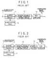
- Fig. 1shows a first example of the conventional image sub-sampling system.
- the apparatus of Fig. 1conducts only the n-dot sub-sampling operation above.
- the systemincludes an inverse quantization circuit 11, a quantization table 12, an inverse discrete cosine transformation circuit 13, and a sub-sampling circuit 14.
- the circuit 11receives as an input thereto a quantization coefficient Sq configured in an 8-element by 8-element matrix to inversely quantize the coefficient Sq.
- a quantization step size Q stored in the quantization table 12is read therefrom to be multiplied by the coefficient Sq, thereby producing data R.
- the obtained data Ris inputted to the circuit 13, which then conducts an inverse discrete cosine transformation for the data R to thereby create output data r.
- the data ris fed to the circuit 14 to be sujected to an n-dot sub-sampling operation, thereby generating conpressed image signal S 2 .
- the quantization coefficient Sq (V,U) in the form of an (8 ⁇ 8) matrixis first delivered to the circuit 11.
- the quantization step size Q(V, U) registered to the table 12is multiplied by each element of the matrix so as to produce inversely quantized data R(V, U).
- the data R(V, U)is then supplied to the circuit 13 to undergo an inverse transformation such that the resultant data is inputted to the circuit 14.
- the data r(V, U) produced from the circuit 13is subjected an n-dot sub-sampling operation in the circuit 14 thereby creating compressed image data S 2 .
- n4
- Fig. 2shows a second example of the image sub-sampling device of the prior art.
- datais delivered to a low-pass filter such that the resultant data is subjected to the n-dot sub-sampling operation.
- This configurationis different from that of Fig. 1 in that a low-pass filter is disposed between the circuits 13 and 14.
- the filter 16reduces the size of a frequency band of the data r(V, U) to 1/n thereof.
- the system of Fig. 2operates substantially in the same fashion as the apparatus of Fig. 1 excepting that the data r(V, U) is passed through the filter 16.
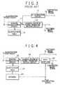
- Fig. 3shows a third example of the conventional image sub-sampling device.
- the inversely quantized data produced from the circuit 11is fed to a dc component extracting circuit 17 to extract dc components therefrom so as to accomplish the image sub-sampling operation without achieving the inverse transformation.
- the apparatus of Fig. 1achieving only the n-dot sub-sampling operation is attended with an aliasing noise.
- the system of Fig. 2includes the low-pass filter to prevent the aliasing noise so as to achieve the n-dot sub-sampling operation after the data is passed through the filter 16. This consequently leads to a drawback that the apparatus is expensive due to adoption of the filter 16.
- the apparatusis advantageous in that the operation time is reduced when software processing is employed for the operation.
- the processing timecannot be reduced and hence the above advantage is obtained even when the configuration of Fig. 3 is adopted.
- EP-A-0,447,269discloses an image data processing system. Inverse quantizing is therein performed by a dequantizer which determines the number of significant questions in a block and outputs an insignificant block signal zero to a DCT unit if no significant coefficient exists. For significant coefficients inverse quantizing is as usual performed by multiplying the quantized coefficients by corresponding values provided by a quantization table.
- JP-A-04,097,678discloses a picture decoding system.
- transformation coefficients corresponding to high-frequency componentsare made zero and inverse conversion is then implemented by a same block size in the case of coding and low pass filtering. Finally the output is reduced by subsampling.
- Another object of the present inventionis to provide an image sub-sampling apparatus capable of selecting an image sub-sampling ratio.
- Fig. 4schematically shows the constitution of an embodiment of the image sub-sampling apparatus in accordance with the present invention.
- the systemincludes an inverse quantization circuit 21, a quantization table 22 containing values of a quantization step size in the format of a table for an inverse quantization, masking means 23 for masking the table 22, an inverse discrete cosine transformation circuit 24, and a sub-sampling circuit 25.
- the circuit 21references the contents of the table 22 to conduct a linear inverse quantization for a quantization coefficient Sq so as to produce inversely quantized data R.
- the means 23replaces each value of a portion of the table 22, primarily, a high-frequency portion with "0", thereby achieving the masking operation.
- each value of data corresponding to the portion masked by the table 22is set to "0".
- the data inversely quantized by the circuit 21is fed to the circuit 24 to undergo an inverse discrete cosine transformation, thereby generating a restored image signal S 1 .
- the signal S 1is then fed to the circuit 25.
- the signal S 1is subjected to an n-dot sub-sampling operation in the circuit 25. Namely, in each of the vertical and horizontal directions, the data is sub-sampled such that every n dots are reduced to one dot, thereby producing a compressed image signal S 2 .
- a quantization coefficient Sq(V, U) in the form of an (8 ⁇ 8) matrixis delivered to the circuit 21.
- a quantization step size A(V, U) stored in the table 22is multiplied by each element of the matrix to create inversely quantized data R(V, U).
- the size Q(V, U) of the table 22is obtained by substituting each value of the high-frequency portion of the table 22 for "0" by the masking means 23.
- Each value of the inverse quantization data corresponding to the portion replaced by "0"becomes to be "0".
- the obtained data R(V, U)is inputted to the circuit 24 to undergo an inverse transformation according to the following expression (1) such that the resultant data is fed to the sub-sampling circuit 25.
- r(i,j)1 4 ⁇ C( u )C( v ) ⁇ cos (2i+1) u ⁇ 16 ⁇ cos (2j+1) v ⁇ 16 ⁇ R( u , v )
- c( v )1 for v ⁇
- r(i, j)indicates an output pixel
- R( u , v )denotes a DCT coefficient.
- each value of the data area beyond 1/n of the original size of the table 22 in the vertical and horizontal directionsis replaced with "0".
- n2
- each value of a portion of Q(V, U) represented with V ⁇ 4 and U ⁇ 4is substituted for "0".
- a portion of the quantization table 22is masked to set each value of a high-frequency portion of the table 22 to "0" such that the inverse quantization is carried out according to the contents of the table 22, thereby preventing occurrence of the aliasing noise.
- the dc componentsare extracted from the inversely quantized data to be outputted without conducting the inverse transformation. Consequently, the image sub-sampling ratio cannot be selected.
- either one of the sub-sampling ratios 1/2, 1/4, and 1/8can be selected according to the n specification signal.
Landscapes
- Engineering & Computer Science (AREA)
- Multimedia (AREA)
- Signal Processing (AREA)
- Physics & Mathematics (AREA)
- Discrete Mathematics (AREA)
- General Physics & Mathematics (AREA)
- Compression Or Coding Systems Of Tv Signals (AREA)
- Compression Of Band Width Or Redundancy In Fax (AREA)
- Compression, Expansion, Code Conversion, And Decoders (AREA)
Description
Claims (4)
- An image sub-sampling apparatus operative in anencoding operation of image data encoded by a discrete cosinetransformation and a linear quantization for sub-sampling theimage data, comprising:characterized by further comprising:inverse quantization means (21) for linearly and inverselyquantizing a quantized coefficient according to aquantization table (22) and thereby producing inversely quantizeddata;inverse discrete cosine transformation means (24) forconducting an inverse discrete cosine transformation for thedata created by the inverse quantization means (21); andsub-sampling means (25) for sub-sampling the datagenerated from the inverse discrete cosine transformationmeans (24) to obtain a dot for every n dots in each of thevertical and horizontal directions of the data and therebyproducing an image signal,the quantization table including a high-frequencyportion,
masking means (23) for masking said portion of saidquantization table to set each value of the portion to "0", wherein
the masking means masks, according to aspecification signal inputted thereto, an area beyond the n-th column and the n-th rowof the quantization table (22) in the vertical and horizontaldirections of the table. thereby setting each value of thearea to "0". - An apparatus as claimed in claim 1, wherein the sub-samplingmeans (25) receives a sub-sampling ratio specification signal to conductthe sub-sampling operation according to the sub-sampling ratio specificationsignal, thereby producing the image signal.
- An apparatus as claimed in claim 1, wherein the sub-samplingmeans (25) is responsive to the input of the sub-sampling ratio specificationsignal for selecting either one of sub-sampling ratios 1/2, 1/4,and 1/8.
- A method of sub-sampling image data encoded by a discretecosine transformation and a linear quantization,said method comprising thesteps of:characterized by the steps of:providing a quantization table (22);linearly and inversely quantizing a quantized coefficientaccording to said quantization table (22) and thereby producing inverselyquantized data;conducting an inverse discrete cosine transformation for the datacreated by the inverse quantization; andsub-sampling the data generated by the inverse discrete cosinetransformation to obtain a dot for every n dots in each of the verticaland horizontal directions of the data and thereby producing animage signal,the quantization table including a high-frequency portion
masking a portion of said quantization table to set each value ofsaid portion to "0", wherein
the masking is performed according to a specification signal whichspecifies that an area beyond the n-th column and the n-th rowof said quantization table is to be set to "0".
Applications Claiming Priority (2)
| Application Number | Priority Date | Filing Date | Title |
|---|---|---|---|
| JP28723092AJPH06141185A (en) | 1992-10-26 | 1992-10-26 | Picture thinning device |
| JP287230/92 | 1992-10-26 |
Publications (2)
| Publication Number | Publication Date |
|---|---|
| EP0595218A1 EP0595218A1 (en) | 1994-05-04 |
| EP0595218B1true EP0595218B1 (en) | 1998-07-08 |
Family
ID=17714727
Family Applications (1)
| Application Number | Title | Priority Date | Filing Date |
|---|---|---|---|
| EP19930117156Expired - LifetimeEP0595218B1 (en) | 1992-10-26 | 1993-10-22 | Image sub-sampling apparatus and method |
Country Status (5)
| Country | Link |
|---|---|
| US (1) | US5565925A (en) |
| EP (1) | EP0595218B1 (en) |
| JP (1) | JPH06141185A (en) |
| KR (1) | KR0128737B1 (en) |
| DE (1) | DE69319539T2 (en) |
Cited By (1)
| Publication number | Priority date | Publication date | Assignee | Title |
|---|---|---|---|---|
| US7215708B2 (en) | 2001-05-22 | 2007-05-08 | Koninklijke Philips Electronics N.V. | Resolution downscaling of video images |
Families Citing this family (13)
| Publication number | Priority date | Publication date | Assignee | Title |
|---|---|---|---|---|
| JP3773585B2 (en)* | 1996-03-29 | 2006-05-10 | 富士通株式会社 | Image encoding device |
| EP0831654B1 (en)* | 1996-09-23 | 2002-07-24 | Daewoo Electronics Co., Ltd | Method and apparatus for encoding a contour image of an object in a video signal |
| US6473533B1 (en)* | 1996-10-25 | 2002-10-29 | Fuji Xerox Co., Ltd. | Image encoding apparatus and image decoding apparatus |
| CN1121122C (en)* | 1996-10-25 | 2003-09-10 | 大宇电子株式会社 | Method and apparatus for encoding contour image of object in video signal |
| AU9680198A (en)* | 1997-10-07 | 1999-04-27 | Thomson Consumer Electronics | Picture masking and compositing in the frequency domain |
| KR100257074B1 (en) | 1998-01-26 | 2000-05-15 | 김영환 | Mosfet and method for manufacturing the same |
| KR100282307B1 (en) | 1998-02-20 | 2001-02-15 | 구자홍 | Digital TV Receive Decoder Device |
| US6717988B2 (en) | 2001-01-11 | 2004-04-06 | Koninklijke Philips Electronics N.V. | Scalable MPEG-2 decoder |
| US6704362B2 (en)* | 2001-07-06 | 2004-03-09 | Koninklijke Philips Electronics N.V. | Resource scalable decoding |
| JP4315980B2 (en)* | 2004-06-15 | 2009-08-19 | シャープ株式会社 | Image compression apparatus, image compression method, and image compression program product |
| US8218634B2 (en)* | 2005-01-13 | 2012-07-10 | Ntt Docomo, Inc. | Nonlinear, in-the-loop, denoising filter for quantization noise removal for hybrid video compression |
| US20060262847A1 (en)* | 2005-05-17 | 2006-11-23 | Benq Corporation | Method of adaptive encoding video signal and apparatus thereof |
| FR2892575B1 (en)* | 2005-10-24 | 2008-04-11 | Sagem Comm Groupe Safran Sa | METHOD FOR DECOMPRESSING A COMPRESSED IMAGE |
Family Cites Families (7)
| Publication number | Priority date | Publication date | Assignee | Title |
|---|---|---|---|---|
| JPH0683435B2 (en)* | 1989-02-03 | 1994-10-19 | 三洋電機株式会社 | Subsample video signal demodulator |
| JPH0828875B2 (en)* | 1989-08-21 | 1996-03-21 | 三菱電機株式会社 | Encoding device and decoding device |
| EP1250010A1 (en)* | 1990-03-16 | 2002-10-16 | Fujitsu Limited | An image data processing system |
| JP2839943B2 (en)* | 1990-08-10 | 1998-12-24 | 富士通株式会社 | Image data restoration method and apparatus |
| JPH0497678A (en)* | 1990-08-15 | 1992-03-30 | Nippon Telegr & Teleph Corp <Ntt> | Picture decoding system |
| JPH0568164A (en)* | 1991-09-06 | 1993-03-19 | Canon Inc | Image reproducing device |
| KR0128245B1 (en)* | 1992-10-07 | 1998-04-02 | 배순훈 | High definition television with divicding pictures e |
- 1992
- 1992-10-26JPJP28723092Apatent/JPH06141185A/enactivePending
- 1993
- 1993-10-22EPEP19930117156patent/EP0595218B1/ennot_activeExpired - Lifetime
- 1993-10-22KRKR1019930021999Apatent/KR0128737B1/ennot_activeExpired - Fee Related
- 1993-10-22DEDE69319539Tpatent/DE69319539T2/ennot_activeExpired - Fee Related
- 1995
- 1995-08-10USUS08/513,409patent/US5565925A/ennot_activeExpired - Lifetime
Cited By (1)
| Publication number | Priority date | Publication date | Assignee | Title |
|---|---|---|---|---|
| US7215708B2 (en) | 2001-05-22 | 2007-05-08 | Koninklijke Philips Electronics N.V. | Resolution downscaling of video images |
Also Published As
| Publication number | Publication date |
|---|---|
| KR0128737B1 (en) | 1998-04-04 |
| DE69319539T2 (en) | 1999-04-15 |
| JPH06141185A (en) | 1994-05-20 |
| DE69319539D1 (en) | 1998-08-13 |
| EP0595218A1 (en) | 1994-05-04 |
| US5565925A (en) | 1996-10-15 |
| KR940009875A (en) | 1994-05-24 |
Similar Documents
| Publication | Publication Date | Title |
|---|---|---|
| EP0595218B1 (en) | Image sub-sampling apparatus and method | |
| US5253075A (en) | Image signal coding/decoding system using adaptive quantization | |
| EP0499303B1 (en) | Method and apparatus for shuffling and deshuffling data | |
| US8165222B2 (en) | Video coder employing pixel transposition | |
| KR100781629B1 (en) | A method for reducing the memory required for decompression by storing compressed information using DCT base technology and a decoder for implementing the method | |
| EP0550012B1 (en) | Apparatus for compression encoding video signals | |
| US6101284A (en) | Methods and systems for optimizing image data compression involving wavelet transform | |
| EP0663778A2 (en) | Image coding method and apparatus therefor | |
| US5216712A (en) | Recording apparatus | |
| EP0734164B1 (en) | Video signal encoding method and apparatus having a classification device | |
| EP0515143B1 (en) | Video signal encoding and decoding apparatus | |
| US5329360A (en) | Multiplexing and demultiplexing image data | |
| EP0542196A2 (en) | Digital video signal recording and reproducing apparatus | |
| US6563946B2 (en) | Image processing apparatus and method | |
| EP0519995B1 (en) | Digital image processing including block edges filtering | |
| EP0340854B1 (en) | Television transmission system including a hybrid encoding circuit | |
| US5963678A (en) | Image signal processing apparatus and method | |
| US5957998A (en) | Discrete cosine transform method | |
| GB2266635A (en) | Image data compression | |
| EP0341780B1 (en) | Television transmission system with differential encoding of transform coefficients | |
| US5353060A (en) | Process and device for the transformation of image data | |
| US20030099466A1 (en) | Image data recording and transmission | |
| JPH0549021A (en) | High efficient coder | |
| KR950008640B1 (en) | Image compression coding method and decoding method for bit fixation | |
| JPH01251973A (en) | Orthogonal transform coding device and orthogonal inverse transform decoding device for video signal |
Legal Events
| Date | Code | Title | Description |
|---|---|---|---|
| PUAI | Public reference made under article 153(3) epc to a published international application that has entered the european phase | Free format text:ORIGINAL CODE: 0009012 | |
| AK | Designated contracting states | Kind code of ref document:A1 Designated state(s):DE FR GB IT NL | |
| 17P | Request for examination filed | Effective date:19940728 | |
| 17Q | First examination report despatched | Effective date:19960822 | |
| GRAG | Despatch of communication of intention to grant | Free format text:ORIGINAL CODE: EPIDOS AGRA | |
| GRAG | Despatch of communication of intention to grant | Free format text:ORIGINAL CODE: EPIDOS AGRA | |
| GRAH | Despatch of communication of intention to grant a patent | Free format text:ORIGINAL CODE: EPIDOS IGRA | |
| GRAH | Despatch of communication of intention to grant a patent | Free format text:ORIGINAL CODE: EPIDOS IGRA | |
| GRAA | (expected) grant | Free format text:ORIGINAL CODE: 0009210 | |
| AK | Designated contracting states | Kind code of ref document:B1 Designated state(s):DE FR GB IT NL | |
| REF | Corresponds to: | Ref document number:69319539 Country of ref document:DE Date of ref document:19980813 | |
| ET | Fr: translation filed | ||
| PLBE | No opposition filed within time limit | Free format text:ORIGINAL CODE: 0009261 | |
| STAA | Information on the status of an ep patent application or granted ep patent | Free format text:STATUS: NO OPPOSITION FILED WITHIN TIME LIMIT | |
| 26N | No opposition filed | ||
| REG | Reference to a national code | Ref country code:GB Ref legal event code:IF02 | |
| REG | Reference to a national code | Ref country code:GB Ref legal event code:732E | |
| NLS | Nl: assignments of ep-patents | Owner name:NEC ELECTRONICS CORPORATION | |
| REG | Reference to a national code | Ref country code:FR Ref legal event code:TP | |
| PGFP | Annual fee paid to national office [announced via postgrant information from national office to epo] | Ref country code:NL Payment date:20081015 Year of fee payment:16 Ref country code:DE Payment date:20081016 Year of fee payment:16 | |
| PGFP | Annual fee paid to national office [announced via postgrant information from national office to epo] | Ref country code:IT Payment date:20081028 Year of fee payment:16 | |
| PGFP | Annual fee paid to national office [announced via postgrant information from national office to epo] | Ref country code:FR Payment date:20081014 Year of fee payment:16 | |
| PGFP | Annual fee paid to national office [announced via postgrant information from national office to epo] | Ref country code:GB Payment date:20081022 Year of fee payment:16 | |
| REG | Reference to a national code | Ref country code:NL Ref legal event code:V1 Effective date:20100501 | |
| REG | Reference to a national code | Ref country code:FR Ref legal event code:ST Effective date:20100630 | |
| PG25 | Lapsed in a contracting state [announced via postgrant information from national office to epo] | Ref country code:NL Free format text:LAPSE BECAUSE OF NON-PAYMENT OF DUE FEES Effective date:20100501 Ref country code:FR Free format text:LAPSE BECAUSE OF NON-PAYMENT OF DUE FEES Effective date:20091102 Ref country code:DE Free format text:LAPSE BECAUSE OF NON-PAYMENT OF DUE FEES Effective date:20100501 | |
| PG25 | Lapsed in a contracting state [announced via postgrant information from national office to epo] | Ref country code:GB Free format text:LAPSE BECAUSE OF NON-PAYMENT OF DUE FEES Effective date:20091022 | |
| PG25 | Lapsed in a contracting state [announced via postgrant information from national office to epo] | Ref country code:IT Free format text:LAPSE BECAUSE OF NON-PAYMENT OF DUE FEES Effective date:20091022 |