EP0594003B1 - Apparatus for applying surgical clips - Google Patents
Apparatus for applying surgical clipsDownload PDFInfo
- Publication number
- EP0594003B1 EP0594003B1EP93116337AEP93116337AEP0594003B1EP 0594003 B1EP0594003 B1EP 0594003B1EP 93116337 AEP93116337 AEP 93116337AEP 93116337 AEP93116337 AEP 93116337AEP 0594003 B1EP0594003 B1EP 0594003B1
- Authority
- EP
- European Patent Office
- Prior art keywords
- clip
- pusher
- jaw members
- advancement
- body portion
- Prior art date
- Legal status (The legal status is an assumption and is not a legal conclusion. Google has not performed a legal analysis and makes no representation as to the accuracy of the status listed.)
- Expired - Lifetime
Links
- 230000007246mechanismEffects0.000claimsdescription24
- 238000007789sealingMethods0.000claimsdescription6
- 239000004519greaseSubstances0.000claimsdescription2
- 229920001296polysiloxanePolymers0.000claimsdescription2
- 230000001419dependent effectEffects0.000claims1
- 230000002452interceptive effectEffects0.000description23
- 238000002788crimpingMethods0.000description13
- 239000000463materialSubstances0.000description10
- 238000000034methodMethods0.000description10
- 230000009471actionEffects0.000description6
- 210000004204blood vesselAnatomy0.000description4
- 230000008901benefitEffects0.000description3
- 229920004142LEXAN™Polymers0.000description2
- 239000004418LexanSubstances0.000description2
- 229910000831SteelInorganic materials0.000description2
- 238000002224dissectionMethods0.000description2
- 238000012976endoscopic surgical procedureMethods0.000description2
- 238000003780insertionMethods0.000description2
- 230000037431insertionEffects0.000description2
- 230000014759maintenance of locationEffects0.000description2
- 230000004044responseEffects0.000description2
- 229910001220stainless steelInorganic materials0.000description2
- 239000010935stainless steelSubstances0.000description2
- 239000010959steelSubstances0.000description2
- 238000001356surgical procedureMethods0.000description2
- RTAQQCXQSZGOHL-UHFFFAOYSA-NTitaniumChemical compound[Ti]RTAQQCXQSZGOHL-UHFFFAOYSA-N0.000description1
- 239000000853adhesiveSubstances0.000description1
- 230000001070adhesive effectEffects0.000description1
- 230000002411adverseEffects0.000description1
- 210000001124body fluidAnatomy0.000description1
- 239000010839body fluidSubstances0.000description1
- 230000000694effectsEffects0.000description1
- 230000002439hemostatic effectEffects0.000description1
- 230000003993interactionEffects0.000description1
- 238000012830laparoscopic surgical procedureMethods0.000description1
- 238000012423maintenanceMethods0.000description1
- 210000000056organAnatomy0.000description1
- 239000004033plasticSubstances0.000description1
- 239000004417polycarbonateSubstances0.000description1
- 229920000515polycarbonatePolymers0.000description1
- 230000002028prematureEffects0.000description1
- 229910052719titaniumInorganic materials0.000description1
- 239000010936titaniumSubstances0.000description1
- 238000003466weldingMethods0.000description1
Images


Classifications
- A—HUMAN NECESSITIES
- A61—MEDICAL OR VETERINARY SCIENCE; HYGIENE
- A61B—DIAGNOSIS; SURGERY; IDENTIFICATION
- A61B17/00—Surgical instruments, devices or methods
- A61B17/12—Surgical instruments, devices or methods for ligaturing or otherwise compressing tubular parts of the body, e.g. blood vessels or umbilical cord
- A61B17/128—Surgical instruments, devices or methods for ligaturing or otherwise compressing tubular parts of the body, e.g. blood vessels or umbilical cord for applying or removing clamps or clips
- A61B17/1285—Surgical instruments, devices or methods for ligaturing or otherwise compressing tubular parts of the body, e.g. blood vessels or umbilical cord for applying or removing clamps or clips for minimally invasive surgery
- A—HUMAN NECESSITIES
- A61—MEDICAL OR VETERINARY SCIENCE; HYGIENE
- A61B—DIAGNOSIS; SURGERY; IDENTIFICATION
- A61B17/00—Surgical instruments, devices or methods
- A61B17/28—Surgical forceps
- A61B17/29—Forceps for use in minimally invasive surgery
- A61B2017/2926—Details of heads or jaws
- A61B2017/2927—Details of heads or jaws the angular position of the head being adjustable with respect to the shaft
- A61B2017/2929—Details of heads or jaws the angular position of the head being adjustable with respect to the shaft with a head rotatable about the longitudinal axis of the shaft
- Y—GENERAL TAGGING OF NEW TECHNOLOGICAL DEVELOPMENTS; GENERAL TAGGING OF CROSS-SECTIONAL TECHNOLOGIES SPANNING OVER SEVERAL SECTIONS OF THE IPC; TECHNICAL SUBJECTS COVERED BY FORMER USPC CROSS-REFERENCE ART COLLECTIONS [XRACs] AND DIGESTS
- Y10—TECHNICAL SUBJECTS COVERED BY FORMER USPC
- Y10S—TECHNICAL SUBJECTS COVERED BY FORMER USPC CROSS-REFERENCE ART COLLECTIONS [XRACs] AND DIGESTS
- Y10S227/00—Elongated-member-driving apparatus
- Y10S227/901—Surgical clip appliers
Definitions
- This inventionrelates to an apparatus for applying surgical clips to body tissue during laparoscopic or endoscopic procedures, and more particularly, to a surgical clip applier configured for selective operation such that in a first mode the feed of a clip into the jaws is initiated by the user and in a second mode it is initiated independent of the user.
- the user of the instrumentreleases the catch mechanism, e.g., by actuating a trigger associated with the frame, thereby freeing the clip pusher to feed the distal-most clip into the jaw members. Thereupon, the jaw members may again be closed to form the clip.
- the maintenance of the clip pusher in a position proximal to the next clip until the user releases the catch mechanismis advantageous for several reasons, including the fact that the jaws will be empty of a clip for tissue dissection and for passage into and out of a trocar sleeve.
- the Thornton deviceincludes a mechanism which enables the user to select the point in time when a clip is to be advanced to the jaws.
- the mechanismincludes a button 100 which is pressed by the user to release a drive link to feed a clip into the jaws.
- the Thornton deviceis intended, inter alia , to reduce the risk that a clip waiting in the jaws may be dislodged and fall into the body (see col. 1, lines 44-59).
- a second commercially available endoscopic multiple clip applierduplicates the structure, function and use of the Endo Clip® applier with one exception, the catch mechanism in the frame is omitted.
- the Ligaclip® appliersee US-A-5171247 (published after the priority date of the present application).
- the clip pusherplaces the next clip in the jaws without further action by the user.
- the Ligaclipsuffers from the disadvantage that a clip is present in the jaws at all times, including times when the user would prefer that the jaws be empty.
- the apparatuscomprises a handle portion, a body portion which extends distally from the handle portion, jaw members positioned adjacent the distal end of the body portion for receiving and subsequently forming a clip, camming means which are operable from the handle portion for camming the jaw members closed to form a clip, storage means for storing a plurality of surgical clips in a position for individual advancement to the jaw members, clip advancement means for individually advancing the clips from the storage means into the jaw members, and control means for selecting between a first mode of operation in which the advancement of a clip from the storage means into the jaw members is initiated by the user and a second mode in which it is initiated independent of the user.
- the clip advancement meansincludes a clip pusher which is at least partially positioned within the body portion of the apparatus.
- a pusher structureis associated with the clip pusher and is positioned within the handle portion of the apparatus.
- the control meansincludes lock means associated with the handle portion that, when properly oriented, releasably locks the pusher structure such that, after a clip is formed by the jaw members, the clip pusher is maintained in a position proximal to the distal-most clip in the storage means.
- the control meansis adapted to be moved between a first position in which the lock means is oriented to releasably lock the pusher structure after a clip is formed by the jaw members ("interactive mode"), and a second position in which the lock means is oriented so as not to releasably lock the pusher structure, i.e., the pusher structure moves independent of the lock means ("non-interactive mode").
- control meansWhen the control means is positioned such that the lock means is in the interactive mode, advancement of a clip into the jaw members is initiated by the user releasing the lock means. In the non-interactive mode, however, advancement of a clip into the jaw members is independent of the user. Movement of the control means between the first and second positions results in corresponding changes to the apparatus' mode of operation.
- a first release meansis associated with the handle portion of the apparatus for manually releasing the lock means to permit the clip pusher to advance a clip into the jaw members.
- the first release meansmay comprise a release trigger which is actuated by the user (with the lock means in the interactive mode) to release the lock means from engagement with the pusher structure.
- the release triggermay be mounted to a release lever which is movable in a longitudinal direction for releasing the lock means.
- the first release meanscomprises a toggle switch having a detent which is biased into releasable engagement with the pusher structure.
- the apparatusmay further comprise second release means associated with the camming means for releasing the lock means (independent of the user) when the lock means is in the non-interactive mode, thereby permitting the clip pusher to advance a clip into the jaw members.
- the second release meansmay comprise a proximal extension to channel structure associated with the camming means.
- the camming meansis movable in a longitudinal direction between a proximal position wherein the jaw members are in a clip receiving position and a distal position wherein the jaw members are in a clip forming position.
- the proximal extension to the channel structureis configured for releasing the lock means when the camming means is in its proximal position which corresponds to the jaw members being in the clip receiving position.
- control meansincludes a sliding selector switch which is associated with the handle portion and which is configured for movement between a first position wherein the first release means is enabled and a second position wherein the second release means is enabled.
- endoscopic proceduresare more common than laparoscopic procedures
- the present inventionshall be discussed in terms of endoscopic procedures and apparatus.
- use herein of terms such as “endoscopic”, “endoscopically”, and “endoscopic portion”, among others,should not be construed to limit the present invention to an apparatus for use only in conjunction with an endoscopic tube.
- the present inventionmay find use in procedures wherein access is limited to a small incision including but not limited to laparoscopic procedures.
- proximalas is traditional, will refer to the end of the apparatus which is closest to the operator, while the term “distal” will refer to the end which is furthest from the operator.
- surgical apparatus 10includes a handle portion 12 and an elongated body portion 14 defining a longitudinal axis which extends distally from the handle portion 12.
- Apparatus 10is configured for selective operation in a user-initiated mode or a user-independent mode through user manipulation of a selector switch 15 which is associated with handle portion 12.
- surgical clipsare individually advanced from the clip storage means into jaw members 24 in response to manipulation of a release trigger 16.
- a surgical clipis individually advanced from the clip storage means into jaws 24 each time the previous clip is formed by the jaw members (until the clip supply is depleted).
- the elongated body portion 14 of surgical apparatus 10is preferably comprises an upper hemi-section 16 and a lower hemi-section 17.
- Elongated body portion 14is preferably integral with handle portion 12, although it can be constructed to be removable from the handle portion 12 (see, e.g., U.S. Patent No. 5,100,420.
- the upper and lower hemi-sections 16, 17are formed of a material that is capable of withstanding the stresses applied by the internal components of the apparatus without deformation or compromise of precision.
- a polycarbonate materialsuch as LEXAN brand material which is marketed by General Electric Corporation has been found to satisfy the strength and deformation requirements.
- the lower hemi-section 17 of the cartridgeincludes upstanding tabs 17a while the upper hemi-section 16 includes corresponding slots (not shown) which are dimensioned and configured to receive the upstanding tabs 17a such that the two hemi-sections may be attached by ultrasonic welding techniques.
- the slotsare dimensioned to receive the upstanding tabs 17a in interference relationship to assist in their securement.
- the hemi-sectionsmay be attached by adhesives or by other known means.
- the proximal end of upper hemi-section 16is provided with a slotted area 19 adapted for engagement with a mechanism disposed within handle portion 12 which facilitates rotation of the elongated portion 14 about the longitudinal axis thereof to increase the range of operability of the instrument.
- Sealing means for obstructing passage of gas through the apparatuse.g., a sealing block and/or silicone grease, as described in U.S. Patent Nos. 5,084,057 and 5,100,420, is positioned within the apparatus, preferably toward the proximal end of body portion 14.
- a plurality of surgical clips 20are positioned within the cartridge and are disposed in a manner for advancement toward a distal end thereof.
- the clipsare of generally U-shaped configuration and are aligned in a row with the leg portions thereof facing distally.
- the clipsare made of titanium which is a material well suited for ligating or clamping blood vessels.
- a jaw blade 26is positioned at the distal end of body portion 14 and includes resilient jaw members 24 dimensioned for reception of the surgical clips 20. Jaw blade 26 is fabricated of a material having a sufficient resiliency to facilitate the relative movement of jaws 24 towards one another to close a clip therebetween, followed by return of the jaws 24 to an original position upon release of clamping forces.
- Jaw blade 26is formed with a plurality of spaced apart apertures 28 which are dimensioned to receive a plurality of corresponding pins or columnar extensions (not shown) molded into the lower hemi-section 17 for positioning the jaw blade 26 with respect to the elongated body portion 14 of the instrument.
- a crimping channel 32which is dimensioned and positioned for slidable movement within body portion 14, defines an elongated channel 34.
- a channel bracket 38preferably of stainless steel, is disposed above jaw blade 26 and defines a pair of depending side walls 40 and 42 which are positioned to be welded to the distal portions of correspondingly positioned and dimensioned upwardly extending side walls 46 and 48 associated with crimping channel 32.
- jaw members 24 of jaw blade 26each have outwardly tapered side walls 50 and 52, respectively, movement of the crimping channel 32 in a distal direction will cause inward movement of jaw members 24 through a camming action, while movement of the crimping channel in the proximal direction will result in corresponding proximal movement of channel bracket 38, thereby relieving the camming forces from jaw members 24 and permitting jaw members 24 to resiliently open to their relaxed condition.
- a tissue stop plate 60is positioned between jaw blade 26 and crimping channel 32, and includes an aperture 62 at the proximal end portion thereof dimensioned for reception of a corresponding pin (not shown) which extends through jaw blade 26 and tissue stop plate 60 to maintain relative alignment therebetween.
- a tab 64is oriented at approximately the same angle as jaws 24 for alignment therewith, and includes an arcuate cut-out portion which is dimensioned to receive a blood vessel.
- a cover plate 66is appropriately dimensioned to rest upon the jaw camming mechanism described hereinabove, and supports the row of surgical clips 20 disposed in body portion 14.
- a clip follower 68is positioned proximal to the surgical clips 20 and has a U-shaped distal end portion 70 configured for engaging and distally advancing clips 20 under the action of a clip feed spring 72.
- Feed spring 72is connected at the proximal end thereof by a pin 74 which is in turn connected to cover plate 66 by an anchor tab 69.
- a clip pusher 78is positioned for longitudinal movement with respect to cover plate 66 between a proximal position and a distal position.
- the upper hemi-section 16 of body portion 14includes a longitudinal slot 82 having a plurality of bridge connections 84, 86, and 88 provided therein.
- Clip pusher bar 78is adapted to be intermeshed with the bridges and, in particular, to be positioned above proximal bridge 88 and below distal bridges 86 and 84, such that proximal bridge 88 acts as a stop mechanism to prevent advancement of the clip follower 68 when an upstanding tab 67 comes into engagement with bridge 88. This engagement will occur when the last clip 20 in the body portion 14 has been advanced and crimped, thereby permitting the clip follower 68 to advance to its distal-most position under action of spring 72.
- the handle portion 12comprises opposed right and left hemi-sections 100 and 102 which are mounted to one another by fasteners or, in the alternative, the hemi-sections may be sonically welded or adhesively attached to one another.
- the right and left hemi-sections 100 and 102 of handle portion 12are fabricated of a hard plastic material such as LEXAN brand material, although the use of other rigid material is envisioned.
- Pivoting handle 18is mounted through an aperture 108 on a pin 104 which extends transversely therethrough.
- Handle 18includes a rearward extension 112 having an arcuate slot 126 defined therein through which a pivot pin 110 extends.
- Another pin 113extends through an aperture 114 in extension 112 and functions as a pivot for a left channel link 116 and a right channel link 118 which extend in a generally forward direction.
- a left pusher link 120 and a right pusher link 122are also provided and are mounted for pivotal movement on pin 110.
- the opposed ends of left channel link 116 and right channel link 118are pivotably mounted to a channel tube 124 by opposed pivot pins, of which pivot pin 127 is one, which are formed integral therewith.
- Pusher links 120 and 122are connected to a C-shaped clasp 125 which is arranged for engagement with spaced apart notched shoulders 136 and 138 formed in a pusher tube 134.
- a main spring member 140operatively connects channel tube 124 with pusher tube 134.
- a pin 119connects the distal end of main spring 140 to channel tube 124 while a pin 131 connects the proximal end thereof to pusher tube 124.
- Spring 140is thus loaded when channel tube 124 and pusher tube 134 are separated by movement of pivoting handle 18 toward handle grip portion 22 which causes distal movement of channel tube 124 and relative proximal movement of pusher tube 134.
- Pusher tube 134is connected to clip pusher bar 78 by proximal end tabs 90 which are inserted into the distal opening 133 of pusher tube 134.
- An annular steel pad 142is positioned between the two members to define an interface therebetween.
- crimping channel 32is connected to channel tube 124 by insertion of the proximal legs 92 thereof into the distal opening 123 of channel tube 124, with an annular steel pad 121 positioned as an interface therebetween.
- the crimping channel 32 and clip pusher bar 78are free to rotate independent of channel tube 124 and pusher tube 134 since their respective proximal legs 90 and 92 are disposed within the distal opening 133 of pusher tube 134 and opening 123 of channel tube 124.
- the benefit of this independent rotational featurewill be discussed in greater detail hereinbelow with respect to a mechanism for rotating the body portion 14 of the surgical apparatus 10 about its longitudinal axis.
- a latch plate 150is pivotably mounted and biased upward toward an aperture plate 146 disposed in the lower wall of channel tube 124 by a spring 148 such that a tongue 156 formed on latch plate 150 engages the aperture plate 146 when channel tube 124 is moved to its proximal position. Engagement of channel tube 124 by latch plate 150 prevents forward movement of the channel tube 124 prior to the advancement of a clip 20 into the opposed jaw members 24 of jaw plate 26. Release of tongue 156 is accomplished by a detent 158 which depends from pusher tube 134 and which disengages latch plate 150 when pusher tube 134 is moved distally under the influence of main spring 140.
- a mechanismis also provided for releasably locking the pusher tube 134 in a proximal position against the influence of main spring 140.
- the mechanismincludes a pusher release member 160, configured as a leaf spring, disposed within handle portion 12 and having a tab 162 configured to engage a slot formed in the bottom wall of pusher tube 134 when pusher tube 134 is moved proximally by pusher links 120 and 122 against the force of the main spring 140.
- This mechanismcooperates with a release trigger 16, in an interactive mode of operation, to initiate placement of a clip 20 in jaw members 24 when desired by the user.
- the mechanismalso prevents premature advancement of the distal-most clip 20 into the jaws 24 of jaw blade 26 which could result in a dropped clip or in unwanted deformation of the clip.
- liberation of the pusher release member 160is accomplished by proximal movement of a release lever 164 via user actuation of release trigger 16.
- Lever 164is supported at the proximal end 165 thereof by a support block formed integral with the right hemi-section 102 of handle portion 12.
- the liberation of pusher release member 160is accomplished by proximal movement of a proximal extension 200 which is mounted to channel tube 124 through an aperture 202 provided at the proximal end thereof.
- selector switch 15may be manipulate in a longitudinal direction within a slotted area 204 between a first position in which the release mechanism associated with trigger 16 is enabled (interactive mode) and a second position in which the proximal extension 200 from channel tube 124 is enabled (non-interactive mode).
- a cam member 206is operatively associated with selector switch 15 through a pin 205 and moves longitudinally therewith to translate a control block 208.
- Control block 208is associated with selector switch 15 through a cam follower pin 210 and is configured to move along a path which is transverse to the longitudinal axis of the instrument as the selector switch 15 is moved longitudinally.
- a groove 212is formed through control block 208 for permitting the passage of the proximal end 165 of release lever 164.
- control block 208In use, when the operator has positioned selector switch 15 in the position which corresponds to the interactive mode of operation, control block 208 permits lever 164 to come into contact with pusher release member 160. Conversely, control block 208 acts to deflect proximal extension 200 from its operational position, preventing proximal extension 200 from contacting pusher release member 160 as channel tube 124 moves proximally to facilitate liberation of pusher tube 134.
- control block 208When the user desires non-interactive operation of apparatus 10, movement of the selector switch 15 to a second position will cause control block 208 to translate transversely so as to permit proximal extension 200 to return to an operational position.
- lever 164will remain in a position for contacting pusher release member 160 although its impact will be overshadowed by the movement of proximal extension 200, i.e., proximal extension 200 will contact release member 160 prior to and independent of lever 164, making lever 164 a redundant structure for this mode of operation.
- Proximal movement of pusher tube 134withdraws clip pusher 78 to a position proximal of the distal-most clip 20 in body portion 14, thereby positioning clip pusher 78 for advancement of the distal-most clip 20 into the jaw members 24 of the jaw blade 26. Retention of the pusher tube 134 in a proximal position by release member 160 also retains clip pusher 78 in a corresponding position until the distal-most clip 20 is to be advanced into the jaws.
- release trigger 16When the instrument is in the interactive mode, proximal movement of release trigger 16 by the user at a desired time will cause release lever 164 to disengage pusher release member 160 from pusher tube 134, thereby releasing pusher tube 134. As a result, pusher tube 134 and clip pusher bar 78 move distally under the bias of main spring 140, advancing the distal-most clip 20 into the jaws 24 of jaw blade 26.
- proximal movement of pusher tube 134proceeds as in the interactive mode, i.e., in response to proximal movement of pusher links 120 and 122.
- Pusher release member 160is biased upward and tab 160 enters slot in the bottom wall of pusher tube 134 when it becomes aligned therewith, thereby retaining pusher tube 134 in a proximal position against the influence of main spring 140.
- channel tube 124is drawn in the proximal direction by main spring 140, thereby bringing proximal extension 200 into contact with pusher release member 160.
- Proximal extension 200releases pusher release member 160 from contact with pusher tube 134, thereby allowing pusher tube 134 to travel in a distal direction under the influence of main spring 140, advancing the distal-most clip 20 into the jaws 24 of jaw blade 26.
- the surgical instrument of the subject inventionis provided with structure for deactivating the clip forming mechanism after all of the clips have been dispensed from the body portion 14 to promote safe operation.
- this safety featureis achieved through interaction of the clip follower 68 with the bridge 88 formed in the upper hemi-section 16 of the cartridge.
- the upstanding tab 67which is provided on the proximal portion of clip follower 68 is dimensioned to engage bridge 88 when clip follower 68 has assumed its distal-most position under the influence of spring 72. This engagement prevents further distal movement the clip follower 68.
- a slotis defined at the distal portion of clip follower 68 which is positioned to engage the nose 80 of clip pusher 78 when the clip follower 68 has advanced to its distal-most position. This engagement prevents further distal movement of clip pusher 78 and pusher tube 134, thus maintaining channel tube 124 locked in its proximal-most position by the tongue 156 of latch plate 150. As a result, further manipulation of pivoting handle 18 toward handle grip 22 is prevented, thereby safely deactivating the clip forming mechanism of the subject invention.
- a rotating collar 170is provided which is constructed of the same material as the handle, and which includes a distal cylindrical nose section 172 and a proximal barrel section 174.
- a proximal face of the barrel section 174is formed with a plurality of proximally extending teeth 176 positioned circumferentially thereabout.
- the cylindrical nose section 172includes an inwardly extending rib 178 at the distal end thereof, which, in the assembled condition, rests within the cylindrical distal opening 182 of the distal end of the handle portion 12.
- a nose piece 184is fitted over the distal cylindrical end 183 of handle portion 12.
- a coiled spring 190is positioned between the shoulders 192 of collar 170 and shoulders 194 which are formed in the body of handle portion 12 to bias the rotatable collar 170 in the proximal direction causing engaging teeth 185 formed in handle portion 12 to engage with the circumferential teeth 176 of collar 170.
- This engagementeffectuates fixation of the rotatable orientation of collar 170.
- the distal cylindrical section 172 of collar 170includes a cylindrical opening which is dimensioned to receive the proximal end of the elongated body portion formed of upper and lower hemi-sections 16 and 17, with a distally positioned tooth 178 positioned to engage the longitudinally extending groove 19 provided in upper hemi-section 16 to cause the body portion 14 to rotate with collar 170.
- proximal legs 90 of clip pusher bar 78are permitted to rotate within the distal end portion 133 of pusher tube 134 and the proximal legs 92 of the crimping channel 32 are permitted to rotate within the distal end portion 123 of channel tube 124.
- the entire elongated body portion 14 of surgical apparatus 10may be selectively rotated by the user through pushing collar 170 in a distal direction sufficient to disengage tooth 180 on the body portion 12 and subsequently rotating collar 170 until the body portion 14 reaches a desired angular orientation. Thereafter, by releasing collar 170 the bias of coiled spring 190 will cause collar 170 to return to an unbiased and locked position.
- surgical apparatus 300comprises a handle portion 312, and an elongated body portion 314 which extends distally from the handle portion 312.
- the body portion 314is identical to the structure described in connection with the first embodiment and is configured for storing a plurality of surgical clips in a position for individual advancement toward jaw members disposed at the distal end thereof.
- Surgical apparatus 300differs from surgical apparatus 100 described hereinabove in the omission of a trigger (see trigger 16 in Fig. 1) and in the structure for selectively controlling the clip advancement structure.
- the control structure of surgical apparatus 300comprises a toggle switch 320 which is pivotably mounted by a pivot pin 322 in a cavity 324 provided in the barrel section 326 of handle portion 312.
- Toggle switch 320is defined by a distal portion 328 and a proximal portion 330.
- a detent 332depends downwardly from the proximal portion 330 and is dimensioned and configured for releasably engaging a keeper notch area 334 which is formed in the pusher tube 134.
- a biasing spring 336preferably in the form of a looped torsion spring, is positioned in cavity 324 proximate to the distal portion 328 of toggle switch 320.
- Biasing spring 336imparts a biasing force on the toggle switch 320 which acts in a clockwise direction with respect to pivot pin 322. As a result, the proximal portion 330 of toggle switch 320 is urged into a position wherein detent 332 is engageable with the keeper notch area 334 of pusher tube 134.
- toggle switch 320When toggle switch 320 is pivoted counterclockwise, pusher tube 134 is freed to translate distally under the bias of main spring 140, driving the clip advancement structure within the body portion 314 forward to advance the distal-most clip 20 into the jaws.
- toggle switch 320is pivoted counterclockwise to the position shown in Fig. 7.
- An abutment featuresecures the toggle switch 320 in the counterclockwise orientation (against the bias of biasing spring 336) and includes a toggle catch 344 which is frictionally engageable within a port 345 formed in cavity 324 adjacent the proximal portion 330 of toggle switch 320 (see Fig. 5).
- the toggle catch 344is configured to impart sufficient frictional retention forces on toggle switch 320 to prevent the biasing spring 336 from urging toggle switch 320 into the clockwise position shown in Fig. 6.
- toggle switch 320With toggle switch 320 in the counterclockwise position of Fig. 7, the instrument operates in the non-interactive manner described hereinabove with respect to apparatus 10. More particularly, as pusher tube 134 is drawn to its proximal-most position through actuation of pivotal handle 18, aperture plate 146 is engaged by a lock member 346 biased by spring 347, thereby maintaining pusher tube 134 in its proximal-most position. Subsequently, after forming a clip, channel tube 134 returns from its distal-most position under the influence of main spring 140 and proximal extension 200 disengages lock member 346 from aperture plate 146. Once lock member 346 is disengaged, pusher tube 134 is released to move under the bias of main spring 140. As a result, clip pusher 78 moves distally to advance the next clip 20 into the jaws.
- the surgical apparatus of the present inventionenjoys many clinical advantages.
- the apparatusWhen operated in the interactive mode, the apparatus provides the advantages associated with the surgeon controlling the placement of a clip in the jaws.
- the surgeonmay operate the apparatus such that the jaws are free of a clip in desired instances, thereby facilitating dissection with the apparatus jaws and passage of the apparatus into and out of a trocar sleeve.
- the apparatusWhen the apparatus is operated in the non-interactive mode, the apparatus provides for more rapid placement of clips into the jaws, e.g. when a plurality of clips are to be placed in rapid succession, as when being placed side-by-side on the same vessel. Allowing the surgeon to select between the two modes of operation is particularly advantageous in that the mode of operation of the device can be selected to suit the clinical situation at each instant in a surgical procedure.
Landscapes
- Health & Medical Sciences (AREA)
- Surgery (AREA)
- Life Sciences & Earth Sciences (AREA)
- Heart & Thoracic Surgery (AREA)
- Nuclear Medicine, Radiotherapy & Molecular Imaging (AREA)
- Vascular Medicine (AREA)
- Engineering & Computer Science (AREA)
- Biomedical Technology (AREA)
- Reproductive Health (AREA)
- Medical Informatics (AREA)
- Molecular Biology (AREA)
- Animal Behavior & Ethology (AREA)
- General Health & Medical Sciences (AREA)
- Public Health (AREA)
- Veterinary Medicine (AREA)
- Surgical Instruments (AREA)
Description
- This invention relates to an apparatus for applying surgical clips to body tissue during laparoscopic or endoscopic procedures, and more particularly, to a surgical clip applier configured for selective operation such that in a first mode the feed of a clip into the jaws is initiated by the user and in a second mode it is initiated independent of the user.
- In laparoscopic and endoscopic surgical procedures, a small incision is made in the patient's body to provide access for a tube or cannula device. Once extended into the patient's body, the cannula allows insertion of various surgical instruments for acting on organs, blood vessels, ducts, or body tissue within the body cavity. Often during these procedures, it is necessary to apply hemostatic clips to blood vessels or ducts to prevent the flow of body fluids therethrough. Instruments for performing endoscopic surgical clip application are known in the art, and include both single clip and multiple clip appliers.
- Endoscopic multiple clip appliers known in the art are described in U.S Patent Nos. 5,084,057 and 5,100,420. The pre-characterising part of
claim 1 below corresponds to what is disclosed in US-A-5100420. In a commercially available embodiment of the invention of the '057 and '420 patents, the Auto Suture® Endo Clip®applier, a clip pusher is provided for individually advancing a clip from an array of stored clips towards a pair of distal jaw members. As each clip is formed by the jaw members, the clip pusher is drawn proximally to a position proximal to the distal-most clip in the clip array. The clip pusher is maintained in this position by a catch mechanism in the frame of the apparatus. At a desired time, the user of the instrument releases the catch mechanism, e.g., by actuating a trigger associated with the frame, thereby freeing the clip pusher to feed the distal-most clip into the jaw members. Thereupon, the jaw members may again be closed to form the clip. The maintenance of the clip pusher in a position proximal to the next clip until the user releases the catch mechanism is advantageous for several reasons, including the fact that the jaws will be empty of a clip for tissue dissection and for passage into and out of a trocar sleeve. - Another multiple clip applier for use in an endoscopic surgical procedure is disclosed in U.S. Patent No. 5,112,343 to Thornton. As with the commercially available Endo Clip® applier, the Thornton device includes a mechanism which enables the user to select the point in time when a clip is to be advanced to the jaws. The mechanism includes a
button 100 which is pressed by the user to release a drive link to feed a clip into the jaws. The Thornton device is intended,interalia, to reduce the risk that a clip waiting in the jaws may be dislodged and fall into the body (see col. 1, lines 44-59). - A second commercially available endoscopic multiple clip applier, the Ethicon Ligaclip®, duplicates the structure, function and use of the Endo Clip® applier with one exception, the catch mechanism in the frame is omitted. For a description of the Ligaclip® applier, see US-A-5171247 (published after the priority date of the present application). Thus, after a clip is formed by the jaws, the clip pusher places the next clip in the jaws without further action by the user. Although offering the potential for relatively small time savings during a surgical procedure, the Ligaclip suffers from the disadvantage that a clip is present in the jaws at all times, including times when the user would prefer that the jaws be empty.
- It is an object of the subject invention to provide a surgical clip applier for applying multiple clips during endoscopic or laparoscopic procedures which is configured for selective operation, such that in a first mode the feed of a clip into the jaws is initiated by the user and in a second mode it is initiated independent of the user.
- It is another object of the subject invention to provide a surgical clip applier for applying multiple clips during endoscopic or laparoscopic procedures which provides the user with a mechanism for selecting between the two modes of operation described above.
- These and other objects of the subject invention will become more readily apparent from the following description of the invention.
- This invention provides an apparatus for applying surgical clips which is defined in
claim 1. The apparatus comprises a handle portion, a body portion which extends distally from the handle portion, jaw members positioned adjacent the distal end of the body portion for receiving and subsequently forming a clip, camming means which are operable from the handle portion for camming the jaw members closed to form a clip, storage means for storing a plurality of surgical clips in a position for individual advancement to the jaw members, clip advancement means for individually advancing the clips from the storage means into the jaw members, and control means for selecting between a first mode of operation in which the advancement of a clip from the storage means into the jaw members is initiated by the user and a second mode in which it is initiated independent of the user. - The clip advancement means includes a clip pusher which is at least partially positioned within the body portion of the apparatus. A pusher structure is associated with the clip pusher and is positioned within the handle portion of the apparatus. The control means includes lock means associated with the handle portion that, when properly oriented, releasably locks the pusher structure such that, after a clip is formed by the jaw members, the clip pusher is maintained in a position proximal to the distal-most clip in the storage means. The control means is adapted to be moved between a first position in which the lock means is oriented to releasably lock the pusher structure after a clip is formed by the jaw members ("interactive mode"), and a second position in which the lock means is oriented so as not to releasably lock the pusher structure, i.e., the pusher structure moves independent of the lock means ("non-interactive mode").
- When the control means is positioned such that the lock means is in the interactive mode, advancement of a clip into the jaw members is initiated by the user releasing the lock means. In the non-interactive mode, however, advancement of a clip into the jaw members is independent of the user. Movement of the control means between the first and second positions results in corresponding changes to the apparatus' mode of operation.
- In one embodiment of the invention, a first release means is associated with the handle portion of the apparatus for manually releasing the lock means to permit the clip pusher to advance a clip into the jaw members. For example, the first release means may comprise a release trigger which is actuated by the user (with the lock means in the interactive mode) to release the lock means from engagement with the pusher structure. The release trigger may be mounted to a release lever which is movable in a longitudinal direction for releasing the lock means. In another preferred embodiment, the first release means comprises a toggle switch having a detent which is biased into releasable engagement with the pusher structure.
- The apparatus may further comprise second release means associated with the camming means for releasing the lock means (independent of the user) when the lock means is in the non-interactive mode, thereby permitting the clip pusher to advance a clip into the jaw members. More particularly, the second release means may comprise a proximal extension to channel structure associated with the camming means. The camming means is movable in a longitudinal direction between a proximal position wherein the jaw members are in a clip receiving position and a distal position wherein the jaw members are in a clip forming position. The proximal extension to the channel structure is configured for releasing the lock means when the camming means is in its proximal position which corresponds to the jaw members being in the clip receiving position.
- In a further embodiment, the control means includes a sliding selector switch which is associated with the handle portion and which is configured for movement between a first position wherein the first release means is enabled and a second position wherein the second release means is enabled.
- Further features of the subject invention will become more readily apparent from the following detailed description of the preferred embodiments taken in conjunction with the accompanying drawings.
- Preferred embodiments of the surgical apparatus of the subject invention will be discussed hereinbelow with respect to drawings wherein:
- Fig. 1 is a perspective view of a surgical apparatus in accordance with a preferred embodiment of the subject invention;
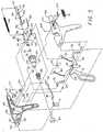
- Fig. 2 is an exploded perspective view of the body portion of the surgical apparatus of Fig. 1;
- Fig. 3 is an exploded perspective view of the handle portion of the surgical apparatus of Fig. 1;
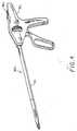
- Fig. 4 is a perspective view a surgical apparatus in accordance with another preferred embodiment of the subject invention;
- Fig. 5 is an exploded perspective view of the handle portion of the surgical apparatus of Fig. 4;
- Fig. 6 is a side elevational view of the handle portion of the surgical apparatus of Fig. 4 in a manual mode of operation; and
- Fig. 7 is a side elevational view of the handle portion of the surgical apparatus of Fig. 4 in an automatic mode of operation.
- Because endoscopic procedures are more common than laparoscopic procedures, the present invention shall be discussed in terms of endoscopic procedures and apparatus. However, use herein of terms such as "endoscopic", "endoscopically", and "endoscopic portion", among others, should not be construed to limit the present invention to an apparatus for use only in conjunction with an endoscopic tube. To the contrary, it is believed that the present invention may find use in procedures wherein access is limited to a small incision including but not limited to laparoscopic procedures. In that regard, applicants specifically refer to the description of sealing means set forth in U.S. Patent Nos. 5,084,057, and 5,100,420.
- In the drawings and in the description which follows, the term "proximal", as is traditional, will refer to the end of the apparatus which is closest to the operator, while the term "distal" will refer to the end which is furthest from the operator.
- Referring now in detail to the drawings in which like reference numerals identify similar or identical elements, a preferred embodiment of the surgical apparatus of the subject invention is illustrated in Fig. 1, and is designated generally by
reference numeral 10. In brief,surgical apparatus 10 includes ahandle portion 12 and anelongated body portion 14 defining a longitudinal axis which extends distally from thehandle portion 12.Apparatus 10 is configured for selective operation in a user-initiated mode or a user-independent mode through user manipulation of aselector switch 15 which is associated withhandle portion 12. In the user-initiated mode of operation, surgical clips are individually advanced from the clip storage means intojaw members 24 in response to manipulation of arelease trigger 16. In the user-independent mode of operation, a surgical clip is individually advanced from the clip storage means intojaws 24 each time the previous clip is formed by the jaw members (until the clip supply is depleted). - Referring now to Fig. 2, the
elongated body portion 14 ofsurgical apparatus 10 is preferably comprises an upper hemi-section 16 and a lower hemi-section 17.Elongated body portion 14 is preferably integral withhandle portion 12, although it can be constructed to be removable from the handle portion 12 (see, e.g., U.S. Patent No. 5,100,420. The upper and lower hemi-sections - The lower hemi-
section 17 of the cartridge includesupstanding tabs 17a while the upper hemi-section 16 includes corresponding slots (not shown) which are dimensioned and configured to receive theupstanding tabs 17a such that the two hemi-sections may be attached by ultrasonic welding techniques. Preferably, the slots are dimensioned to receive theupstanding tabs 17a in interference relationship to assist in their securement. However, the hemi-sections may be attached by adhesives or by other known means. In addition, the proximal end of upper hemi-section 16 is provided with a slottedarea 19 adapted for engagement with a mechanism disposed withinhandle portion 12 which facilitates rotation of theelongated portion 14 about the longitudinal axis thereof to increase the range of operability of the instrument. Sealing means for obstructing passage of gas through the apparatus, e.g., a sealing block and/or silicone grease, as described in U.S. Patent Nos. 5,084,057 and 5,100,420, is positioned within the apparatus, preferably toward the proximal end ofbody portion 14. - A plurality of
surgical clips 20 are positioned within the cartridge and are disposed in a manner for advancement toward a distal end thereof. The clips are of generally U-shaped configuration and are aligned in a row with the leg portions thereof facing distally. Preferably, the clips are made of titanium which is a material well suited for ligating or clamping blood vessels. Ajaw blade 26 is positioned at the distal end ofbody portion 14 and includesresilient jaw members 24 dimensioned for reception of the surgical clips 20.Jaw blade 26 is fabricated of a material having a sufficient resiliency to facilitate the relative movement ofjaws 24 towards one another to close a clip therebetween, followed by return of thejaws 24 to an original position upon release of clamping forces. Stainless steel has been found to be a suitable material which is capable of withstanding the requisite number of clamping cycles without adverse effect.Jaw blade 26 is formed with a plurality of spaced apart apertures 28 which are dimensioned to receive a plurality of corresponding pins or columnar extensions (not shown) molded into the lower hemi-section 17 for positioning thejaw blade 26 with respect to theelongated body portion 14 of the instrument. - As best seen in Fig. 2, a crimping
channel 32, which is dimensioned and positioned for slidable movement withinbody portion 14, defines anelongated channel 34. Achannel bracket 38, preferably of stainless steel, is disposed abovejaw blade 26 and defines a pair of dependingside walls side walls 46 and 48 associated with crimpingchannel 32. Once assembled, crimpingchannel 32 andchannel bracket 38 together form a slidable housing of rectangular configuration which surroundsjaw blade 26. Moreover, since thejaw members 24 ofjaw blade 26 each have outwardly taperedside walls channel 32 in a distal direction will cause inward movement ofjaw members 24 through a camming action, while movement of the crimping channel in the proximal direction will result in corresponding proximal movement ofchannel bracket 38, thereby relieving the camming forces fromjaw members 24 and permittingjaw members 24 to resiliently open to their relaxed condition. - A
tissue stop plate 60 is positioned betweenjaw blade 26 and crimpingchannel 32, and includes anaperture 62 at the proximal end portion thereof dimensioned for reception of a corresponding pin (not shown) which extends throughjaw blade 26 and tissue stopplate 60 to maintain relative alignment therebetween. At the distal portion of thetissue stop plate 60, atab 64 is oriented at approximately the same angle asjaws 24 for alignment therewith, and includes an arcuate cut-out portion which is dimensioned to receive a blood vessel. - Referring still to Fig. 2, a
cover plate 66 is appropriately dimensioned to rest upon the jaw camming mechanism described hereinabove, and supports the row ofsurgical clips 20 disposed inbody portion 14. Aclip follower 68 is positioned proximal to thesurgical clips 20 and has a U-shapeddistal end portion 70 configured for engaging and distally advancingclips 20 under the action of aclip feed spring 72.Feed spring 72 is connected at the proximal end thereof by apin 74 which is in turn connected to coverplate 66 by an anchor tab 69. Aclip pusher 78 is positioned for longitudinal movement with respect to coverplate 66 between a proximal position and a distal position. Engagement of the distal-most clip bypusher bar 78 is facilitated through thedistal nose 80 ofclip pusher bar 78. Movement ofclip pusher bar 78 between a proximal position and a distal position results in positioning ofnose 80 behindsuccessive clips 20 and individual advancement ofsuccessive clips 20 intojaws 24 ofjaw blade 26. - The upper hemi-
section 16 ofbody portion 14 includes alongitudinal slot 82 having a plurality ofbridge connections Clip pusher bar 78 is adapted to be intermeshed with the bridges and, in particular, to be positioned aboveproximal bridge 88 and belowdistal bridges proximal bridge 88 acts as a stop mechanism to prevent advancement of theclip follower 68 when anupstanding tab 67 comes into engagement withbridge 88. This engagement will occur when thelast clip 20 in thebody portion 14 has been advanced and crimped, thereby permitting theclip follower 68 to advance to its distal-most position under action ofspring 72. Clip pusher 78 and crimpingchannel 32 are each operatively connected to structure withinhandle portion 14 which facilitate their respective actions during use ofapparatus 10. In particular,proximal end portion 90 ofclip pusher 78 andproximal end portion 92 of crimpingchannel 32 each cooperate with structure withinhandle portion 12. Turning now to Fig. 3, thehandle portion 12 comprises opposed right and left hemi-sections sections handle portion 12 are fabricated of a hard plastic material such as LEXAN brand material, although the use of other rigid material is envisioned.- Pivoting
handle 18 is mounted through anaperture 108 on apin 104 which extends transversely therethrough.Handle 18 includes arearward extension 112 having an arcuate slot 126 defined therein through which apivot pin 110 extends. Anotherpin 113 extends through anaperture 114 inextension 112 and functions as a pivot for aleft channel link 116 and aright channel link 118 which extend in a generally forward direction. Aleft pusher link 120 and aright pusher link 122 are also provided and are mounted for pivotal movement onpin 110. The opposed ends ofleft channel link 116 andright channel link 118 are pivotably mounted to achannel tube 124 by opposed pivot pins, of whichpivot pin 127 is one, which are formed integral therewith. Pusher links 120 and 122 are connected to a C-shapedclasp 125 which is arranged for engagement with spaced apart notchedshoulders pusher tube 134. Thus, manipulation of pivotinghandle 18 will cause corresponding translation ofpusher links pusher tube 134 proximally withinhandle portion 12. Amain spring member 140 operatively connectschannel tube 124 withpusher tube 134. In particular, apin 119 connects the distal end ofmain spring 140 tochannel tube 124 while apin 131 connects the proximal end thereof topusher tube 124.Spring 140 is thus loaded whenchannel tube 124 andpusher tube 134 are separated by movement of pivotinghandle 18 towardhandle grip portion 22 which causes distal movement ofchannel tube 124 and relative proximal movement ofpusher tube 134. - When a
surgical clip 20 has been positioned within thejaws 24 ofjaw blade 26, manipulation of pivotinghandle 18 towardshand grip 22 will cause distal and pivotal movement ofchannel links channel tube 124 and corresponding distal movement of crimpingchannel 32. This action causeschannel bracket 38, together with crimpingchannel 32 to engage and move thejaw members 24 ofjaw blade 26 toward one another, thereby forming thesurgical clip 20 positioned therebetween. Pusher tube 134 is connected to clippusher bar 78 byproximal end tabs 90 which are inserted into thedistal opening 133 ofpusher tube 134. Anannular steel pad 142 is positioned between the two members to define an interface therebetween. Similarly, crimpingchannel 32 is connected to channeltube 124 by insertion of theproximal legs 92 thereof into thedistal opening 123 ofchannel tube 124, with anannular steel pad 121 positioned as an interface therebetween. As a result, the crimpingchannel 32 andclip pusher bar 78 are free to rotate independent ofchannel tube 124 andpusher tube 134 since their respectiveproximal legs distal opening 133 ofpusher tube 134 and opening 123 ofchannel tube 124. The benefit of this independent rotational feature will be discussed in greater detail hereinbelow with respect to a mechanism for rotating thebody portion 14 of thesurgical apparatus 10 about its longitudinal axis.- As best seen in Fig. 3, a
latch plate 150 is pivotably mounted and biased upward toward an aperture plate 146 disposed in the lower wall ofchannel tube 124 by aspring 148 such that atongue 156 formed onlatch plate 150 engages the aperture plate 146 whenchannel tube 124 is moved to its proximal position. Engagement ofchannel tube 124 bylatch plate 150 prevents forward movement of thechannel tube 124 prior to the advancement of aclip 20 into theopposed jaw members 24 ofjaw plate 26. Release oftongue 156 is accomplished by adetent 158 which depends frompusher tube 134 and which disengageslatch plate 150 whenpusher tube 134 is moved distally under the influence ofmain spring 140. - A mechanism is also provided for releasably locking the
pusher tube 134 in a proximal position against the influence ofmain spring 140. The mechanism includes apusher release member 160, configured as a leaf spring, disposed withinhandle portion 12 and having atab 162 configured to engage a slot formed in the bottom wall ofpusher tube 134 whenpusher tube 134 is moved proximally bypusher links main spring 140. This mechanism cooperates with arelease trigger 16, in an interactive mode of operation, to initiate placement of aclip 20 injaw members 24 when desired by the user. The mechanism also prevents premature advancement of thedistal-most clip 20 into thejaws 24 ofjaw blade 26 which could result in a dropped clip or in unwanted deformation of the clip. - In the interactive mode, liberation of the
pusher release member 160 is accomplished by proximal movement of arelease lever 164 via user actuation ofrelease trigger 16.Lever 164 is supported at the proximal end 165 thereof by a support block formed integral with the right hemi-section 102 ofhandle portion 12. In the non-interactive mode of operation, the liberation ofpusher release member 160 is accomplished by proximal movement of aproximal extension 200 which is mounted tochannel tube 124 through anaperture 202 provided at the proximal end thereof. - To select between the interactive and non-interactive modes of operation, the user may manipulate
selector switch 15 in a longitudinal direction within a slottedarea 204 between a first position in which the release mechanism associated withtrigger 16 is enabled (interactive mode) and a second position in which theproximal extension 200 fromchannel tube 124 is enabled (non-interactive mode). Acam member 206 is operatively associated withselector switch 15 through apin 205 and moves longitudinally therewith to translate acontrol block 208.Control block 208 is associated withselector switch 15 through acam follower pin 210 and is configured to move along a path which is transverse to the longitudinal axis of the instrument as theselector switch 15 is moved longitudinally. Agroove 212 is formed through control block 208 for permitting the passage of the proximal end 165 ofrelease lever 164. - In use, when the operator has positioned
selector switch 15 in the position which corresponds to the interactive mode of operation, control block 208 permits lever 164 to come into contact withpusher release member 160. Conversely, control block 208 acts to deflectproximal extension 200 from its operational position, preventingproximal extension 200 from contactingpusher release member 160 aschannel tube 124 moves proximally to facilitate liberation ofpusher tube 134. When the user desires non-interactive operation ofapparatus 10, movement of theselector switch 15 to a second position will cause control block 208 to translate transversely so as to permitproximal extension 200 to return to an operational position. In this orientation ofselector switch 15,lever 164 will remain in a position for contactingpusher release member 160 although its impact will be overshadowed by the movement ofproximal extension 200, i.e.,proximal extension 200 will contactrelease member 160 prior to and independent oflever 164, making lever 164 a redundant structure for this mode of operation. - Manipulation of pivoting
handle 18 towardhandle grip 22 causespusher links pusher tube 134 by engagement of C-shapedclasp 125 with theshoulders pusher tube 134. Proximal movement ofpusher tube 134 will continue withpusher release member 160 continuously biased upward untiltab 162 enters the slot 161 in the bottom wall ofpusher tube 134, thereby retainingpusher tube 134 in a desired position against the influence ofmain spring 140. Proximal movement ofpusher tube 134 withdrawsclip pusher 78 to a position proximal of thedistal-most clip 20 inbody portion 14, thereby positioningclip pusher 78 for advancement of thedistal-most clip 20 into thejaw members 24 of thejaw blade 26. Retention of thepusher tube 134 in a proximal position byrelease member 160 also retainsclip pusher 78 in a corresponding position until thedistal-most clip 20 is to be advanced into the jaws. - When the instrument is in the interactive mode, proximal movement of
release trigger 16 by the user at a desired time will causerelease lever 164 to disengagepusher release member 160 frompusher tube 134, thereby releasingpusher tube 134. As a result,pusher tube 134 andclip pusher bar 78 move distally under the bias ofmain spring 140, advancing thedistal-most clip 20 into thejaws 24 ofjaw blade 26. - When
surgical apparatus 10 is in the non-interactive mode of operation, proximal movement ofpusher tube 134 proceeds as in the interactive mode, i.e., in response to proximal movement ofpusher links Pusher release member 160 is biased upward andtab 160 enters slot in the bottom wall ofpusher tube 134 when it becomes aligned therewith, thereby retainingpusher tube 134 in a proximal position against the influence ofmain spring 140. After asurgical clip 20 is formed byjaws 24,channel tube 124 is drawn in the proximal direction bymain spring 140, thereby bringingproximal extension 200 into contact withpusher release member 160.Proximal extension 200 releasespusher release member 160 from contact withpusher tube 134, thereby allowingpusher tube 134 to travel in a distal direction under the influence ofmain spring 140, advancing thedistal-most clip 20 into thejaws 24 ofjaw blade 26. - As stated briefly above, the surgical instrument of the subject invention is provided with structure for deactivating the clip forming mechanism after all of the clips have been dispensed from the
body portion 14 to promote safe operation. As best seen in Fig. 2, this safety feature is achieved through interaction of theclip follower 68 with thebridge 88 formed in the upper hemi-section 16 of the cartridge. In particular, theupstanding tab 67 which is provided on the proximal portion ofclip follower 68 is dimensioned to engagebridge 88 whenclip follower 68 has assumed its distal-most position under the influence ofspring 72. This engagement prevents further distal movement theclip follower 68. Additionally, a slot is defined at the distal portion ofclip follower 68 which is positioned to engage thenose 80 ofclip pusher 78 when theclip follower 68 has advanced to its distal-most position. This engagement prevents further distal movement ofclip pusher 78 andpusher tube 134, thus maintainingchannel tube 124 locked in its proximal-most position by thetongue 156 oflatch plate 150. As a result, further manipulation of pivotinghandle 18 towardhandle grip 22 is prevented, thereby safely deactivating the clip forming mechanism of the subject invention. - Referring once again to Fig. 2, the surgical apparatus of the subject invention is provided with a mechanism for rotating the
elongated body portion 14 of the instrument about the longitudinal axis thereof relative to thehandle portion 12. To accomplish this movement, arotating collar 170 is provided which is constructed of the same material as the handle, and which includes a distalcylindrical nose section 172 and aproximal barrel section 174. A proximal face of thebarrel section 174 is formed with a plurality of proximally extendingteeth 176 positioned circumferentially thereabout. Thecylindrical nose section 172 includes an inwardly extendingrib 178 at the distal end thereof, which, in the assembled condition, rests within the cylindricaldistal opening 182 of the distal end of thehandle portion 12. In addition, anose piece 184 is fitted over the distalcylindrical end 183 ofhandle portion 12. - A
coiled spring 190 is positioned between theshoulders 192 ofcollar 170 and shoulders 194 which are formed in the body ofhandle portion 12 to bias therotatable collar 170 in the proximal direction causing engaging teeth 185 formed inhandle portion 12 to engage with thecircumferential teeth 176 ofcollar 170. This engagement effectuates fixation of the rotatable orientation ofcollar 170. The distalcylindrical section 172 ofcollar 170 includes a cylindrical opening which is dimensioned to receive the proximal end of the elongated body portion formed of upper and lower hemi-sections tooth 178 positioned to engage thelongitudinally extending groove 19 provided in upper hemi-section 16 to cause thebody portion 14 to rotate withcollar 170. In addition, theproximal legs 90 ofclip pusher bar 78 are permitted to rotate within thedistal end portion 133 ofpusher tube 134 and theproximal legs 92 of the crimpingchannel 32 are permitted to rotate within thedistal end portion 123 ofchannel tube 124. As a result, the entireelongated body portion 14 ofsurgical apparatus 10 may be selectively rotated by the user through pushingcollar 170 in a distal direction sufficient to disengagetooth 180 on thebody portion 12 and subsequently rotatingcollar 170 until thebody portion 14 reaches a desired angular orientation. Thereafter, by releasingcollar 170 the bias of coiledspring 190 will causecollar 170 to return to an unbiased and locked position. - Another preferred embodiment of the surgical apparatus of the subject invention is illustrated in Fig. 4, and is designated generally by
reference numeral 300. Briefly,surgical apparatus 300 comprises ahandle portion 312, and anelongated body portion 314 which extends distally from thehandle portion 312. Thebody portion 314 is identical to the structure described in connection with the first embodiment and is configured for storing a plurality of surgical clips in a position for individual advancement toward jaw members disposed at the distal end thereof.Surgical apparatus 300 differs fromsurgical apparatus 100 described hereinabove in the omission of a trigger (seetrigger 16 in Fig. 1) and in the structure for selectively controlling the clip advancement structure. - Referring to Fig. 5, the control structure of
surgical apparatus 300 comprises atoggle switch 320 which is pivotably mounted by apivot pin 322 in acavity 324 provided in thebarrel section 326 ofhandle portion 312.Toggle switch 320 is defined by adistal portion 328 and aproximal portion 330. Adetent 332 depends downwardly from theproximal portion 330 and is dimensioned and configured for releasably engaging akeeper notch area 334 which is formed in thepusher tube 134. A biasingspring 336, preferably in the form of a looped torsion spring, is positioned incavity 324 proximate to thedistal portion 328 oftoggle switch 320.Biasing spring 336 imparts a biasing force on thetoggle switch 320 which acts in a clockwise direction with respect to pivotpin 322. As a result, theproximal portion 330 oftoggle switch 320 is urged into a position whereindetent 332 is engageable with thekeeper notch area 334 ofpusher tube 134. - In operation and with toggle switch in its clockwise orientation (see Fig. 6), as
pusher tube 134 traverses thebarrel section 336 ofhandle portion 312 in a proximal direction under the influence of pusher links 340 and 342, as described in connection withsurgical apparatus 10 hereinabove,detent 332 releasably engages thekeeper notch area 334, thereby preventingpusher tube 134 from returning to its normal, distal position. Consequently, the clip advancement structure associated withpusher tube 134 remains in a pre-advancement position proximal to thedistal-most clip 20 disposed within thebody portion 314 of the instrument. With thetoggle switch 320 in this clockwise orientation,surgical instrument 300 is in an interactive mode of operation. Accordingly, advancement of thedistal-most clip 20 into the jaws associated with the distal end of thebody portion 314 of the instrument does not occur until the user releases detent 332 fromkeeper notch 334 by manipulatingtoggle switch 320 counterclockwise. Whentoggle switch 320 is pivoted counterclockwise,pusher tube 134 is freed to translate distally under the bias ofmain spring 140, driving the clip advancement structure within thebody portion 314 forward to advance thedistal-most clip 20 into the jaws. - Should the user of
surgical apparatus 300 prefer at any point to operate the apparatus in a non-interactive mode,toggle switch 320 is pivoted counterclockwise to the position shown in Fig. 7. An abutment feature secures thetoggle switch 320 in the counterclockwise orientation (against the bias of biasing spring 336) and includes atoggle catch 344 which is frictionally engageable within aport 345 formed incavity 324 adjacent theproximal portion 330 of toggle switch 320 (see Fig. 5). Thetoggle catch 344 is configured to impart sufficient frictional retention forces ontoggle switch 320 to prevent thebiasing spring 336 from urgingtoggle switch 320 into the clockwise position shown in Fig. 6. - With
toggle switch 320 in the counterclockwise position of Fig. 7, the instrument operates in the non-interactive manner described hereinabove with respect toapparatus 10. More particularly, aspusher tube 134 is drawn to its proximal-most position through actuation ofpivotal handle 18, aperture plate 146 is engaged by alock member 346 biased byspring 347, thereby maintainingpusher tube 134 in its proximal-most position. Subsequently, after forming a clip,channel tube 134 returns from its distal-most position under the influence ofmain spring 140 andproximal extension 200 disengages lockmember 346 from aperture plate 146. Oncelock member 346 is disengaged,pusher tube 134 is released to move under the bias ofmain spring 140. As a result,clip pusher 78 moves distally to advance thenext clip 20 into the jaws. - The surgical apparatus of the present invention enjoys many clinical advantages. When operated in the interactive mode, the apparatus provides the advantages associated with the surgeon controlling the placement of a clip in the jaws. For example, the surgeon may operate the apparatus such that the jaws are free of a clip in desired instances, thereby facilitating dissection with the apparatus jaws and passage of the apparatus into and out of a trocar sleeve. When the apparatus is operated in the non-interactive mode, the apparatus provides for more rapid placement of clips into the jaws, e.g. when a plurality of clips are to be placed in rapid succession, as when being placed side-by-side on the same vessel. Allowing the surgeon to select between the two modes of operation is particularly advantageous in that the mode of operation of the device can be selected to suit the clinical situation at each instant in a surgical procedure.
- The claims which follow identify embodiments of the invention additional to those described in detail above.
Claims (12)
- An apparatus for applying surgical clips comprising:a) a handle portion (12);b) a body portion (14) extending distally from said handle portion;c) jaw members (24) positioned adjacent the distal end of the body portion and movable between an open position for receiving a clip (20) and a closed position for forming the clip;d) camming means (32) operable from the handle portion and cooperative with the jaw members for camming the jaw members closed to form the clip;e) storage means (66) disposed within said body portion proximate the jaw members for storing a plurality of clips in a position for individual advancement to the jaw members;f) clip advancement means (78) for individually advancing clips from the storage means into the jaw members; and characterised by:g) control means (15) operatively associated with said handle portion for selecting between a first mode in which advancement of a clip from said storage means to said jaw members is effectuated by manually releasing said clip advancement means from a preadvancement position and a second mode in which said clip advancement means is automatically released from said pre-advancement position as said jaw members move from said closed position to said open position.
- An apparatus as recited in Claim 1, wherein said clip advancement means comprises a clip pusher (78) operatively disposed in said body portion.
- An apparatus as recited in Claim 2, wherein said control means includes means for releasably locking a pusher tube (134) associated with said clip pusher in a locked position wherein said clip pusher is in a position proximal to a distal-most clip in said storage means corresponding to said pre-advancement position.
- An apparatus as recited in Claims 1 or 2, wherein said control means includes a selector (15) for moving a locking mechanism (160) operatively associated with said clip advancement means between an operational position and a non-operational position.
- An apparatus as recited in Claim 4 as dependent on claim 2, wherein the clip pusher cooperates with a pusher tube, said locking mechanism being configured to releasably engage said pusher tube when said locking mechanism is in said operational position.
- An apparatus as recited in Claim 5, further comprising a release trigger (16) operatively associated with a release lever (164) disposed in said handle portion, said release lever being movable in a longitudinal direction to release said locking mechanism from engagement with said clip pusher.
- An apparatus as recited in Claim 6, further comprising a channel tube (124) associated with said camming means and having a proximal projection (200) extending therefrom for releasing said locking mechanism (160) from said non-operational position.
- An apparatus as recited in any one of the preceding Claims, further comprising means (170) for rotating said body portion about a longitudinal axis thereof relative to said handle portion.
- An apparatus as recited in Claim 8, wherein said means for rotating said body portion further comprises means (176, 190, 185) for selectively maintaining said body portion at a predetermined angle of rotation relative to said handle portion.
- An apparatus as recited in any one of the preceding Claims, wherein said control means includes a slide switch (15) positioned on said handle portion and configured for longitudinal movement between a first position which corresponds to said first mode and a second position which corresponds to said second mode.
- An apparatus according to any one of the preceding Claims, further comprising sealing means for obstructing the passage of gas through said body portion.
- An apparatus according to Claim 11, wherein said sealing means comprises a sealing block and silicone grease.
Applications Claiming Priority (2)
| Application Number | Priority Date | Filing Date | Title |
|---|---|---|---|
| US07/959,190US5300081A (en) | 1992-10-09 | 1992-10-09 | Surgical clip applier having clip advancement control |
| US959190 | 1992-10-09 |
Publications (2)
| Publication Number | Publication Date |
|---|---|
| EP0594003A1 EP0594003A1 (en) | 1994-04-27 |
| EP0594003B1true EP0594003B1 (en) | 1997-08-20 |
Family
ID=25501760
Family Applications (1)
| Application Number | Title | Priority Date | Filing Date |
|---|---|---|---|
| EP93116337AExpired - LifetimeEP0594003B1 (en) | 1992-10-09 | 1993-10-08 | Apparatus for applying surgical clips |
Country Status (4)
| Country | Link |
|---|---|
| US (1) | US5300081A (en) |
| EP (1) | EP0594003B1 (en) |
| CA (1) | CA2107404A1 (en) |
| DE (1) | DE69313235T2 (en) |
Cited By (21)
| Publication number | Priority date | Publication date | Assignee | Title |
|---|---|---|---|---|
| US8814884B2 (en) | 2007-03-26 | 2014-08-26 | Covidien Lp | Endoscopic surgical clip applier |
| US8845659B2 (en) | 2010-02-25 | 2014-09-30 | Covidien Lp | Articulating endoscopic surgical clip applier |
| US8894665B2 (en) | 2008-08-29 | 2014-11-25 | Covidien Lp | Endoscopic surgical clip applier |
| US8920438B2 (en) | 2004-10-08 | 2014-12-30 | Covidien Lp | Apparatus for applying surgical clips |
| US8961542B2 (en) | 2010-07-28 | 2015-02-24 | Covidien Lp | Articulating clip applier cartridge |
| US8968337B2 (en) | 2010-07-28 | 2015-03-03 | Covidien Lp | Articulating clip applier |
| US9011464B2 (en) | 2010-11-02 | 2015-04-21 | Covidien Lp | Self-centering clip and jaw |
| US9011465B2 (en) | 2004-10-08 | 2015-04-21 | Covidien Lp | Endoscopic surgical clip applier |
| US9113892B2 (en) | 2013-01-08 | 2015-08-25 | Covidien Lp | Surgical clip applier |
| US9186136B2 (en) | 2009-12-09 | 2015-11-17 | Covidien Lp | Surgical clip applier |
| US9186153B2 (en) | 2011-01-31 | 2015-11-17 | Covidien Lp | Locking cam driver and jaw assembly for clip applier |
| US9358015B2 (en) | 2008-08-29 | 2016-06-07 | Covidien Lp | Endoscopic surgical clip applier with wedge plate |
| US9364216B2 (en) | 2011-12-29 | 2016-06-14 | Covidien Lp | Surgical clip applier with integrated clip counter |
| US9364239B2 (en) | 2011-12-19 | 2016-06-14 | Covidien Lp | Jaw closure mechanism for a surgical clip applier |
| US9408610B2 (en) | 2012-05-04 | 2016-08-09 | Covidien Lp | Surgical clip applier with dissector |
| US9439654B2 (en) | 2008-08-29 | 2016-09-13 | Covidien Lp | Endoscopic surgical clip applier |
| US9480477B2 (en) | 2006-10-17 | 2016-11-01 | Covidien Lp | Apparatus for applying surgical clips |
| US9498227B2 (en) | 2007-04-11 | 2016-11-22 | Covidien Lp | Surgical clip applier |
| US9526501B2 (en) | 2009-12-15 | 2016-12-27 | Covidien Lp | Surgical clip applier |
| US9532787B2 (en) | 2012-05-31 | 2017-01-03 | Covidien Lp | Endoscopic clip applier |
| US9549741B2 (en) | 2008-08-25 | 2017-01-24 | Covidien Lp | Surgical clip applier and method of assembly |
Families Citing this family (206)
| Publication number | Priority date | Publication date | Assignee | Title |
|---|---|---|---|---|
| US5797931A (en)* | 1992-06-04 | 1998-08-25 | Olympus Optical Co., Ltd. | Tissue-fixing surgical instrument, tissue-fixing device, and method of fixing tissues |
| USD354564S (en) | 1993-06-25 | 1995-01-17 | Richard-Allan Medical Industries, Inc. | Surgical clip applier |
| ATE209875T1 (en)* | 1993-07-21 | 2001-12-15 | Charles H Klieman | SURGICAL INSTRUMENT FOR ENDOSCOPIC AND GENERAL OPERATIONS |
| US5827323A (en)* | 1993-07-21 | 1998-10-27 | Charles H. Klieman | Surgical instrument for endoscopic and general surgery |
| US5792165A (en)* | 1993-07-21 | 1998-08-11 | Charles H. Klieman | Endoscopic instrument with detachable end effector |
| US5858018A (en)* | 1993-08-25 | 1999-01-12 | Apollo Camera, Llc | Low profile tool for applying spring action ligation clips |
| US5474566A (en)* | 1994-05-05 | 1995-12-12 | United States Surgical Corporation | Self-contained powered surgical apparatus |
| DE4415891A1 (en)* | 1994-05-05 | 1995-11-09 | Wilo Medizintechnik Gmbh | Surgical staple gun |
| USRE38445E1 (en) | 1994-05-05 | 2004-02-24 | Tyco Healthcare Group, Lp | Pistols for setting surgical clamps |
| US5637108A (en)* | 1994-06-15 | 1997-06-10 | United States Surgical Corporation | Surgical handle having a controlled leak passage |
| US5562655A (en)* | 1994-08-12 | 1996-10-08 | United States Surgical Corporation | Surgical apparatus having a universal handle for actuating various attachments |
| US5462558A (en)* | 1994-08-29 | 1995-10-31 | United States Surgical Corporation | Suture clip applier |
| US5626585A (en)* | 1994-09-16 | 1997-05-06 | United States Surgical Corporation | Ligating clip advance |
| US5769857A (en)* | 1996-06-11 | 1998-06-23 | Mgf Group Inc. | Ligating clip applier |
| US6231565B1 (en) | 1997-06-18 | 2001-05-15 | United States Surgical Corporation | Robotic arm DLUs for performing surgical tasks |
| US6228098B1 (en)* | 1998-07-10 | 2001-05-08 | General Surgical Innovations, Inc. | Apparatus and method for surgical fastening |
| US6350269B1 (en) | 1999-03-01 | 2002-02-26 | Apollo Camera, L.L.C. | Ligation clip and clip applier |
| US6626929B1 (en)* | 1999-04-15 | 2003-09-30 | Classic Wire Cut | Surgical instrument with locking ratchet apparatus and method |
| KR20020081295A (en) | 2000-02-04 | 2002-10-26 | 이매진 메디칼 테크놀로지즈 캘리포니아, 인코포레이티드. | Surgical clip applier |
| US6500188B2 (en) | 2001-01-29 | 2002-12-31 | Ethicon Endo-Surgery, Inc. | Ultrasonic surgical instrument with finger actuator |
| US20040054364A1 (en)* | 2002-02-08 | 2004-03-18 | Ernest Aranyi | Ultrasonic surgical instrument |
| US20080214967A1 (en)* | 2004-02-17 | 2008-09-04 | Ernest Aranyi | Ultrasonic surgical instrument |
| EP2000106B1 (en) | 2001-02-08 | 2010-06-09 | Tyco Healthcare Group Lp | Ultrasonic surgical instrument |
| US10285694B2 (en) | 2001-10-20 | 2019-05-14 | Covidien Lp | Surgical stapler with timer and feedback display |
| US7464847B2 (en)* | 2005-06-03 | 2008-12-16 | Tyco Healthcare Group Lp | Surgical stapler with timer and feedback display |
| ES2321181T3 (en)* | 2002-04-15 | 2009-06-03 | Wilson-Cook Medical Inc. | HEMOSTATIC CLAMPING DEVICE. |
| EP1499246B1 (en)* | 2002-04-29 | 2009-11-11 | Tyco Healthcare Group Lp | Ligation clip applier |
| US7678125B2 (en)* | 2002-11-12 | 2010-03-16 | Apollo Camera, L.L.C. | Surgical ligation clip |
| US20040193213A1 (en)* | 2003-03-11 | 2004-09-30 | Ernest Aranyi | Clip applying apparatus with curved jaws, and clip |
| EP1608272B1 (en) | 2003-03-11 | 2017-01-25 | Covidien LP | Clip applying apparatus with angled jaw |
| US8172870B2 (en)* | 2003-06-09 | 2012-05-08 | Microline Surgical, Inc. | Ligation clip applier |
| US7758625B2 (en)* | 2003-09-12 | 2010-07-20 | Abbott Vascular Solutions Inc. | Delivery system for medical devices |
| US7572266B2 (en)* | 2003-10-21 | 2009-08-11 | Young Wayne P | Clip applier tool having a discharge configuration |
| US20050149016A1 (en)* | 2003-12-29 | 2005-07-07 | Centum Research Llc | Laparoscopic device and method of female sterilization |
| US8123757B2 (en)* | 2003-12-31 | 2012-02-28 | Depuy Spine, Inc. | Inserter instrument and implant clip |
| US20050187575A1 (en)* | 2004-02-12 | 2005-08-25 | Hallbeck M. S. | Ergonomic handle and articulating laparoscopic tool |
| WO2006034403A2 (en) | 2004-09-23 | 2006-03-30 | Tyco Healthcare Group, Lp | Clip applying apparatus and ligation clip |
| US9763668B2 (en) | 2004-10-08 | 2017-09-19 | Covidien Lp | Endoscopic surgical clip applier |
| US8409222B2 (en) | 2004-10-08 | 2013-04-02 | Covidien Lp | Endoscopic surgical clip applier |
| US7819886B2 (en) | 2004-10-08 | 2010-10-26 | Tyco Healthcare Group Lp | Endoscopic surgical clip applier |
| US8523882B2 (en)* | 2005-04-14 | 2013-09-03 | Ethicon Endo-Surgery, Inc. | Clip advancer mechanism with alignment features |
| US7731724B2 (en)* | 2005-04-14 | 2010-06-08 | Ethicon Endo-Surgery, Inc. | Surgical clip advancement and alignment mechanism |
| US7297149B2 (en) | 2005-04-14 | 2007-11-20 | Ethicon Endo-Surgery, Inc. | Surgical clip applier methods |
| US7686820B2 (en)* | 2005-04-14 | 2010-03-30 | Ethicon Endo-Surgery, Inc. | Surgical clip applier ratchet mechanism |
| US7740641B2 (en) | 2005-04-14 | 2010-06-22 | Ethicon Endo-Surgery, Inc. | Clip applier with migrational resistance features |
| US7699860B2 (en)* | 2005-04-14 | 2010-04-20 | Ethicon Endo-Surgery, Inc. | Surgical clip |
| US20090014002A1 (en)* | 2005-04-14 | 2009-01-15 | Honeywell International Inc. | Air filter assembly |
| US7261724B2 (en)* | 2005-04-14 | 2007-08-28 | Ethicon Endo-Surgery, Inc. | Surgical clip advancement mechanism |
| US8038686B2 (en)* | 2005-04-14 | 2011-10-18 | Ethicon Endo-Surgery, Inc. | Clip applier configured to prevent clip fallout |
| US7288098B2 (en) | 2005-04-14 | 2007-10-30 | Ethicon Endo-Surgery, Inc. | Force limiting mechanism for medical instrument |
| US11291443B2 (en) | 2005-06-03 | 2022-04-05 | Covidien Lp | Surgical stapler with timer and feedback display |
| CA2609970C (en) | 2005-06-03 | 2014-08-12 | Tyco Healthcare Group Lp | Battery powered surgical instrument |
| US9326776B2 (en)* | 2005-09-29 | 2016-05-03 | Applied Medical Resources Corporation | Manually actuated surgical clip applier |
| US7738401B2 (en)* | 2005-10-20 | 2010-06-15 | At&T Intellectual Property I, L.P. | System and method for overlaying a hierarchical network design on a full mesh network |
| US20070089433A1 (en)* | 2005-10-20 | 2007-04-26 | Smurfit-Stone Container Enterprises, Inc. | Methods and systems for monitoring a shelf life of a product stored within a container |
| US20070173866A1 (en)* | 2006-01-23 | 2007-07-26 | Tyco Healthcare Group, Lp | Surgical hemostatic clip |
| JP5175833B2 (en)* | 2006-03-10 | 2013-04-03 | クック メディカル テクノロジーズ エルエルシー | Medical device capable of drawing target tissue into clip arm housing chamber |
| USD625009S1 (en) | 2006-03-24 | 2010-10-05 | Tyco Healthcare Group Lp | Surgical clip applier |
| USD629101S1 (en) | 2006-03-24 | 2010-12-14 | Tyco Healthcare Group Lp | Surgical clip applier |
| EP2020925B1 (en)* | 2006-06-01 | 2013-07-10 | Cook Medical Technologies LLC | Release mechanisms for a clip device |
| US8012166B2 (en)* | 2006-07-06 | 2011-09-06 | Centum Research Llc | Laparoscopic instrument tip and method of specimen collection |
| ATE547143T1 (en)* | 2006-07-14 | 2012-03-15 | Cook Medical Technologies Llc | PAPILLA SPREADERS |
| JP5244816B2 (en)* | 2006-12-05 | 2013-07-24 | クック メディカル テクノロジーズ エルエルシー | Combination therapy hemostatic clip |
| JP2008192187A (en)* | 2007-01-31 | 2008-08-21 | Fujitsu Ltd | Head control device, storage device, and contact detection method |
| US7431188B1 (en) | 2007-03-15 | 2008-10-07 | Tyco Healthcare Group Lp | Surgical stapling apparatus with powered articulation |
| US11259801B2 (en) | 2007-04-13 | 2022-03-01 | Covidien Lp | Powered surgical instrument |
| US7950560B2 (en) | 2007-04-13 | 2011-05-31 | Tyco Healthcare Group Lp | Powered surgical instrument |
| US8800837B2 (en) | 2007-04-13 | 2014-08-12 | Covidien Lp | Powered surgical instrument |
| US20080255413A1 (en) | 2007-04-13 | 2008-10-16 | Michael Zemlok | Powered surgical instrument |
| US7823760B2 (en) | 2007-05-01 | 2010-11-02 | Tyco Healthcare Group Lp | Powered surgical stapling device platform |
| US7931660B2 (en) | 2007-05-10 | 2011-04-26 | Tyco Healthcare Group Lp | Powered tacker instrument |
| US8579910B2 (en) | 2007-05-18 | 2013-11-12 | DePuy Synthes Products, LLC | Insertion blade assembly and method of use |
| US7922063B2 (en) | 2007-10-31 | 2011-04-12 | Tyco Healthcare Group, Lp | Powered surgical instrument |
| CA2706860C (en) | 2007-11-26 | 2017-08-01 | Eastern Virginia Medical School | Magnaretractor system and method |
| US8056565B2 (en) | 2008-08-25 | 2011-11-15 | Tyco Healthcare Group Lp | Surgical clip applier and method of assembly |
| US20110208212A1 (en)* | 2010-02-19 | 2011-08-25 | Zergiebel Earl M | Surgical clip applier |
| US8585717B2 (en) | 2008-08-29 | 2013-11-19 | Covidien Lp | Single stroke endoscopic surgical clip applier |
| US8906033B2 (en) | 2009-03-30 | 2014-12-09 | DePuy Synthes Products, LLC | Cervical motion disc inserter |
| US8821514B2 (en) | 2009-06-08 | 2014-09-02 | Covidien Lp | Powered tack applier |
| US8342378B2 (en)* | 2009-08-17 | 2013-01-01 | Covidien Lp | One handed stapler |
| US8262679B2 (en)* | 2009-10-09 | 2012-09-11 | Ethicon Endo-Surgery, Inc. | Clip advancer |
| US8267945B2 (en)* | 2009-10-09 | 2012-09-18 | Ethicon Endo-Surgery, Inc. | Clip advancer with lockout mechanism |
| US8734469B2 (en)* | 2009-10-13 | 2014-05-27 | Covidien Lp | Suture clip applier |
| US8683895B2 (en)* | 2010-02-23 | 2014-04-01 | Kensey Nash Corporation | Single revolution snap action drive for surgical fasteners |
| TW201130457A (en)* | 2010-03-03 | 2011-09-16 | Ming-Huei Cheng | Automatic clip applier for clamping two ligating clips simultaneously |
| US10136898B2 (en) | 2010-03-09 | 2018-11-27 | Teleflex Medical Incorporated | Narrow profile surgical ligation clip |
| US8764774B2 (en) | 2010-11-09 | 2014-07-01 | Cook Medical Technologies Llc | Clip system having tether segments for closure |
| US9775623B2 (en) | 2011-04-29 | 2017-10-03 | Covidien Lp | Surgical clip applier including clip relief feature |
| EP2755578A2 (en) | 2011-09-15 | 2014-07-23 | Teleflex Medical Incorporated | Manual surgical ligation clip applier |
| EP2755576B1 (en) | 2011-09-15 | 2019-05-22 | Teleflex Medical Incorporated | Automatic surgical ligation clip applier |
| EP2768418B1 (en) | 2011-10-19 | 2017-07-19 | Ethicon Endo-Surgery, Inc. | Clip applier adapted for use with a surgical robot |
| US20130131697A1 (en) | 2011-11-21 | 2013-05-23 | Covidien Lp | Surgical clip applier |
| US9968362B2 (en) | 2013-01-08 | 2018-05-15 | Covidien Lp | Surgical clip applier |
| US9750500B2 (en) | 2013-01-18 | 2017-09-05 | Covidien Lp | Surgical clip applier |
| US8764769B1 (en) | 2013-03-12 | 2014-07-01 | Levita Magnetics International Corp. | Grasper with magnetically-controlled positioning |
| US9775624B2 (en) | 2013-08-27 | 2017-10-03 | Covidien Lp | Surgical clip applier |
| WO2015112645A1 (en) | 2014-01-21 | 2015-07-30 | Levita Magnetics International Corp. | Laparoscopic graspers and systems therefor |
| USD798686S1 (en) | 2014-09-05 | 2017-10-03 | Mohammed Ali Barakat | Ergonomical trigger handle |
| FR3028747B1 (en)* | 2014-11-26 | 2020-11-27 | Ladjali Mustapha Dr | BODY TISSUE TREATMENT DEVICE AND ASSOCIATED TREATMENT NECESSARY |
| US10702278B2 (en) | 2014-12-02 | 2020-07-07 | Covidien Lp | Laparoscopic surgical ligation clip applier |
| US9931124B2 (en) | 2015-01-07 | 2018-04-03 | Covidien Lp | Reposable clip applier |
| CN107205747B (en) | 2015-01-15 | 2020-09-08 | 柯惠有限合伙公司 | Reusable endoscopic surgical clip applier |
| US10292712B2 (en) | 2015-01-28 | 2019-05-21 | Covidien Lp | Surgical clip applier with integrated cutter |
| US10159491B2 (en) | 2015-03-10 | 2018-12-25 | Covidien Lp | Endoscopic reposable surgical clip applier |
| WO2016168377A1 (en) | 2015-04-13 | 2016-10-20 | Levita Magnetics International Corp. | Retractor systems, devices, and methods for use |
| ES2895900T3 (en) | 2015-04-13 | 2022-02-23 | Levita Magnetics Int Corp | Magnetically controlled location handle |
| CN108348259B (en) | 2015-11-03 | 2020-12-11 | 柯惠有限合伙公司 | Endoscopic Surgical Fixture Applicator |
| US10390831B2 (en) | 2015-11-10 | 2019-08-27 | Covidien Lp | Endoscopic reposable surgical clip applier |
| US10702280B2 (en) | 2015-11-10 | 2020-07-07 | Covidien Lp | Endoscopic reposable surgical clip applier |
| US10905425B2 (en) | 2015-11-10 | 2021-02-02 | Covidien Lp | Endoscopic reposable surgical clip applier |
| EP3399902B1 (en) | 2016-01-08 | 2024-06-12 | Levita Magnetics International Corp. | One-operator surgical system |
| CN108472044B (en) | 2016-01-11 | 2021-04-16 | 柯惠有限合伙公司 | endoscope-reserved surgical clip applier |
| AU2016388454A1 (en) | 2016-01-18 | 2018-07-19 | Covidien Lp | Endoscopic surgical clip applier |
| CA2958160A1 (en) | 2016-02-24 | 2017-08-24 | Covidien Lp | Endoscopic reposable surgical clip applier |
| WO2018027788A1 (en) | 2016-08-11 | 2018-02-15 | Covidien Lp | Endoscopic surgical clip applier and clip applying systems |
| CN109640844B (en) | 2016-08-25 | 2021-08-06 | 柯惠Lp公司 | Endoscopic Surgical Clip Appliers and Applicator Systems |
| US10660651B2 (en) | 2016-10-31 | 2020-05-26 | Covidien Lp | Endoscopic reposable surgical clip applier |
| US10639044B2 (en) | 2016-10-31 | 2020-05-05 | Covidien Lp | Ligation clip module and clip applier |
| US10492795B2 (en) | 2016-11-01 | 2019-12-03 | Covidien Lp | Endoscopic surgical clip applier |
| US10610236B2 (en) | 2016-11-01 | 2020-04-07 | Covidien Lp | Endoscopic reposable surgical clip applier |
| US10426489B2 (en) | 2016-11-01 | 2019-10-01 | Covidien Lp | Endoscopic reposable surgical clip applier |
| US10709455B2 (en) | 2017-02-02 | 2020-07-14 | Covidien Lp | Endoscopic surgical clip applier |
| US10758244B2 (en) | 2017-02-06 | 2020-09-01 | Covidien Lp | Endoscopic surgical clip applier |
| US11116514B2 (en) | 2017-02-06 | 2021-09-14 | Covidien Lp | Surgical clip applier with user feedback feature |
| US10660725B2 (en) | 2017-02-14 | 2020-05-26 | Covidien Lp | Endoscopic surgical clip applier including counter assembly |
| US10603038B2 (en) | 2017-02-22 | 2020-03-31 | Covidien Lp | Surgical clip applier including inserts for jaw assembly |
| US11583291B2 (en) | 2017-02-23 | 2023-02-21 | Covidien Lp | Endoscopic surgical clip applier |
| US10548602B2 (en) | 2017-02-23 | 2020-02-04 | Covidien Lp | Endoscopic surgical clip applier |
| US11020137B2 (en) | 2017-03-20 | 2021-06-01 | Levita Magnetics International Corp. | Directable traction systems and methods |
| US10433842B2 (en) | 2017-04-07 | 2019-10-08 | Lexington Medical, Inc. | Surgical handle assembly |
| US10675043B2 (en) | 2017-05-04 | 2020-06-09 | Covidien Lp | Reposable multi-fire surgical clip applier |
| US10722235B2 (en) | 2017-05-11 | 2020-07-28 | Covidien Lp | Spring-release surgical clip |
| US11311295B2 (en) | 2017-05-15 | 2022-04-26 | Covidien Lp | Adaptive powered stapling algorithm with calibration factor |
| WO2018232128A1 (en) | 2017-06-14 | 2018-12-20 | Epic Medical Concepts & Innovations, Inc. | Laparoscopic devices and related methods |
| US10912560B2 (en) | 2017-06-23 | 2021-02-09 | Lexington Medical, Inc. | Surgical reloadable cartridge assembly |
| US10639032B2 (en) | 2017-06-30 | 2020-05-05 | Covidien Lp | Endoscopic surgical clip applier including counter assembly |
| US10660723B2 (en) | 2017-06-30 | 2020-05-26 | Covidien Lp | Endoscopic reposable surgical clip applier |
| US10675112B2 (en) | 2017-08-07 | 2020-06-09 | Covidien Lp | Endoscopic surgical clip applier including counter assembly |
| US10863992B2 (en) | 2017-08-08 | 2020-12-15 | Covidien Lp | Endoscopic surgical clip applier |
| US10932790B2 (en) | 2017-08-08 | 2021-03-02 | Covidien Lp | Geared actuation mechanism and surgical clip applier including the same |
| US10786262B2 (en) | 2017-08-09 | 2020-09-29 | Covidien Lp | Endoscopic reposable surgical clip applier |
| US10786263B2 (en) | 2017-08-15 | 2020-09-29 | Covidien Lp | Endoscopic reposable surgical clip applier |
| US10835341B2 (en) | 2017-09-12 | 2020-11-17 | Covidien Lp | Endoscopic surgical clip applier and handle assemblies for use therewith |
| US10653429B2 (en) | 2017-09-13 | 2020-05-19 | Covidien Lp | Endoscopic surgical clip applier |
| US10758245B2 (en) | 2017-09-13 | 2020-09-01 | Covidien Lp | Clip counting mechanism for surgical clip applier |
| US10835260B2 (en) | 2017-09-13 | 2020-11-17 | Covidien Lp | Endoscopic surgical clip applier and handle assemblies for use therewith |
| US11207066B2 (en) | 2017-10-30 | 2021-12-28 | Covidien Lp | Apparatus for endoscopic procedures |
| US10987104B2 (en) | 2017-10-30 | 2021-04-27 | Covidien Lp | Apparatus for endoscopic procedures |
| US12185949B2 (en) | 2017-10-30 | 2025-01-07 | Covidien Lp | Apparatus for endoscopic procedures |
| US10828036B2 (en) | 2017-11-03 | 2020-11-10 | Covidien Lp | Endoscopic surgical clip applier and handle assemblies for use therewith |
| US10945734B2 (en) | 2017-11-03 | 2021-03-16 | Covidien Lp | Rotation knob assemblies and surgical instruments including the same |
| US11116513B2 (en) | 2017-11-03 | 2021-09-14 | Covidien Lp | Modular surgical clip cartridge |
| US11376015B2 (en) | 2017-11-03 | 2022-07-05 | Covidien Lp | Endoscopic surgical clip applier and handle assemblies for use therewith |
| US10932791B2 (en) | 2017-11-03 | 2021-03-02 | Covidien Lp | Reposable multi-fire surgical clip applier |
| US10722236B2 (en) | 2017-12-12 | 2020-07-28 | Covidien Lp | Endoscopic reposable surgical clip applier |
| US10959737B2 (en) | 2017-12-13 | 2021-03-30 | Covidien Lp | Reposable multi-fire surgical clip applier |
| US10849630B2 (en) | 2017-12-13 | 2020-12-01 | Covidien Lp | Reposable multi-fire surgical clip applier |
| US10743887B2 (en) | 2017-12-13 | 2020-08-18 | Covidien Lp | Reposable multi-fire surgical clip applier |
| US11051827B2 (en) | 2018-01-16 | 2021-07-06 | Covidien Lp | Endoscopic surgical instrument and handle assemblies for use therewith |
| US10820910B2 (en)* | 2018-02-15 | 2020-11-03 | Ethicon Llc | Surgical clip applier with articulating joint path for surgical clips |
| US10993721B2 (en) | 2018-04-25 | 2021-05-04 | Covidien Lp | Surgical clip applier |
| US11376003B2 (en) | 2018-07-05 | 2022-07-05 | Lexington Medical, Inc. | Surgical handle articulation assembly |
| US11497490B2 (en) | 2018-07-09 | 2022-11-15 | Covidien Lp | Powered surgical devices including predictive motor control |
| US10786273B2 (en) | 2018-07-13 | 2020-09-29 | Covidien Lp | Rotation knob assemblies for handle assemblies |
| US12137902B2 (en) | 2018-07-25 | 2024-11-12 | Covidien Lp | Adaptive anti-twitch algorithm for powered surgical devices |
| US11259887B2 (en) | 2018-08-10 | 2022-03-01 | Covidien Lp | Feedback mechanisms for handle assemblies |
| US11278267B2 (en) | 2018-08-13 | 2022-03-22 | Covidien Lp | Latch assemblies and surgical instruments including the same |
| US11033256B2 (en) | 2018-08-13 | 2021-06-15 | Covidien Lp | Linkage assembly for reusable surgical handle assemblies |
| US11219463B2 (en) | 2018-08-13 | 2022-01-11 | Covidien Lp | Bilateral spring for surgical instruments and surgical instruments including the same |
| US11246601B2 (en) | 2018-08-13 | 2022-02-15 | Covidien Lp | Elongated assemblies for surgical clip appliers and surgical clip appliers incorporating the same |
| US11051828B2 (en) | 2018-08-13 | 2021-07-06 | Covidien Lp | Rotation knob assemblies and surgical instruments including same |
| US11253267B2 (en) | 2018-08-13 | 2022-02-22 | Covidien Lp | Friction reduction mechanisms for handle assemblies |
| US11344316B2 (en) | 2018-08-13 | 2022-05-31 | Covidien Lp | Elongated assemblies for surgical clip appliers and surgical clip appliers incorporating the same |
| US11166723B2 (en) | 2018-09-21 | 2021-11-09 | Lexington Medical, Inc. | Surgical handle assembly modes of operation |
| US11147566B2 (en) | 2018-10-01 | 2021-10-19 | Covidien Lp | Endoscopic surgical clip applier |
| US11197734B2 (en) | 2018-10-30 | 2021-12-14 | Covidien Lp | Load sensing devices for use in surgical instruments |
| US11369372B2 (en) | 2018-11-28 | 2022-06-28 | Covidien Lp | Surgical stapler adapter with flexible cable assembly, flexible fingers, and contact clips |
| US10856871B2 (en) | 2019-01-16 | 2020-12-08 | Lexington Medical, Inc. | Advancing a toothed rack of a surgical handle assembly |
| US11202635B2 (en) | 2019-02-04 | 2021-12-21 | Covidien Lp | Programmable distal tilt position of end effector for powered surgical devices |
| US11376006B2 (en) | 2019-02-06 | 2022-07-05 | Covidien Lp | End effector force measurement with digital drive circuit |
| US11219461B2 (en) | 2019-03-08 | 2022-01-11 | Covidien Lp | Strain gauge stabilization in a surgical device |
| US11524398B2 (en) | 2019-03-19 | 2022-12-13 | Covidien Lp | Gear drive mechanisms for surgical instruments |
| CN110037765B (en)* | 2019-05-24 | 2023-12-08 | 杭州圣石科技股份有限公司 | Continuous clip applier |
| US11779340B2 (en) | 2020-01-02 | 2023-10-10 | Covidien Lp | Ligation clip loading device |
| US11723669B2 (en) | 2020-01-08 | 2023-08-15 | Covidien Lp | Clip applier with clip cartridge interface |
| US11298131B2 (en) | 2020-01-15 | 2022-04-12 | Lexington Medical, Inc. | Multidirectional apparatus |
| US11458244B2 (en) | 2020-02-07 | 2022-10-04 | Covidien Lp | Irrigating surgical apparatus with positive pressure fluid |
| US11553913B2 (en) | 2020-02-11 | 2023-01-17 | Covidien Lp | Electrically-determining tissue cut with surgical stapling apparatus |
| US12114866B2 (en) | 2020-03-26 | 2024-10-15 | Covidien Lp | Interoperative clip loading device |
| US11116501B1 (en) | 2020-04-10 | 2021-09-14 | Lexington Medical, Inc. | Surgical handle articulation assemblies |
| US12029470B2 (en) | 2020-05-21 | 2024-07-09 | Covidien Lp | Simultaneous RF monopolar calibration using a shared return electrode |
| US11622768B2 (en) | 2020-07-13 | 2023-04-11 | Covidien Lp | Methods and structure for confirming proper assembly of powered surgical stapling systems |
| US12193884B2 (en) | 2020-11-17 | 2025-01-14 | Covidien Lp | Contactless force measurement of motor torque in powered surgical device |
| US11653919B2 (en) | 2020-11-24 | 2023-05-23 | Covidien Lp | Stapler line reinforcement continuity |
| US11744580B2 (en) | 2020-11-24 | 2023-09-05 | Covidien Lp | Long stapler reloads with continuous cartridge |
| CN114680995B (en)* | 2020-12-31 | 2025-08-29 | 江苏风和医疗器材股份有限公司 | A clip applier |
| US11864757B2 (en) | 2021-01-15 | 2024-01-09 | Lexington, Medical, Inc. | Reloadable cartridge assembly |
| US11622764B2 (en) | 2021-04-27 | 2023-04-11 | Lexington Medical, Inc. | Surgical handle assembly |
| US12016556B2 (en) | 2021-05-03 | 2024-06-25 | Covidien Lp | Handheld electromechanical surgical system |
| US11684362B2 (en) | 2021-06-07 | 2023-06-27 | Covidien Lp | Handheld electromechanical surgical system |
| US12343009B2 (en) | 2021-06-07 | 2025-07-01 | Lexington Medical, Inc. | Motorized surgical handle assembly |
| US11771432B2 (en) | 2021-06-29 | 2023-10-03 | Covidien Lp | Stapling and cutting to default values in the event of strain gauge data integrity loss |
| WO2023034616A1 (en) | 2021-09-03 | 2023-03-09 | Lexington Medical, Inc. | Staple line surgical buttress |
| US12161341B2 (en) | 2021-09-07 | 2024-12-10 | Covidien Lp | Slow speed staple and staple relaxation for stapling optimization |
| US11832823B2 (en) | 2022-02-08 | 2023-12-05 | Covidien Lp | Determination of anvil release during anastomosis |
| US12419648B2 (en) | 2022-09-26 | 2025-09-23 | Covidien Lp | Two-part fasteners for surgical clip appliers and surgical clip appliers for deploying the same |
Family Cites Families (117)
| Publication number | Priority date | Publication date | Assignee | Title |
|---|---|---|---|---|
| US2008367A (en)* | 1934-10-26 | 1935-07-16 | Armstrong Bros Tool Co | Detent |
| US2741248A (en)* | 1953-12-16 | 1956-04-10 | Allen & Hanburys Ltd | Surgical saws |
| US2968041A (en)* | 1958-09-25 | 1961-01-17 | John F Skold | Applicator for surgical clamps |
| US3585985A (en)* | 1968-12-16 | 1971-06-22 | Wilbur J Gould | Surgical instrument for biopsy |
| US3631707A (en)* | 1969-06-13 | 1972-01-04 | Weck & Co Inc Edward | Hemostatic clip applicator |
| US3603310A (en)* | 1969-06-30 | 1971-09-07 | Parke Davis & Co | Disposable syringe |
| US3848773A (en)* | 1972-03-07 | 1974-11-19 | New England Nuclear Corp | Radioactive gas dispensing device |
| US3777538A (en)* | 1972-03-15 | 1973-12-11 | Weck & Co Edward | Surgical clip applicator |
| US3856016A (en)* | 1972-11-03 | 1974-12-24 | H Davis | Method for mechanically applying an occlusion clip to an anatomical tubular structure |
| US3954108A (en)* | 1972-11-03 | 1976-05-04 | Davis Hugh J | Occlusion clip and instrument for applying same |
| US3834392A (en)* | 1973-02-01 | 1974-09-10 | Kli Inc | Laparoscopy system |
| DE2330182A1 (en) | 1973-06-14 | 1975-01-02 | Wolf Gmbh Richard | PLIERS FOR SETTING TANTALUM CLIPS |
| US3870048A (en)* | 1973-07-30 | 1975-03-11 | In Bae Yoon | Device for sterilizing the human female or male by ligation |
| US3989049A (en)* | 1973-07-30 | 1976-11-02 | In Bae Yoon | Method of applying an elastic ring to an anatomical tubular structure |
| US3882854A (en)* | 1973-08-23 | 1975-05-13 | Research Corp | Surgical clip and applicator |
| US4101063A (en)* | 1973-10-30 | 1978-07-18 | Nikolai Nikolaevich Kapitanov | Surgical instrument for ligating tubular organs in deep cavities |
| JPS552966Y2 (en)* | 1974-02-08 | 1980-01-24 | ||
| US4027510A (en)* | 1974-05-15 | 1977-06-07 | Siegfried Hiltebrandt | Forceps |
| US3955581A (en)* | 1974-10-18 | 1976-05-11 | United States Surgical Corporation | Three-stage surgical instrument |
| US4374523A (en)* | 1974-10-29 | 1983-02-22 | Yoon In B | Occlusion ring applicator |
| GB1486351A (en)* | 1975-06-06 | 1977-09-21 | Rocket Of London Ltd | Surgical clip applicator |
| US4103680A (en)* | 1975-08-15 | 1978-08-01 | In Bae Yoon | Multiple occlusion ring applicator and method |
| US4085743A (en)* | 1976-03-02 | 1978-04-25 | In Bae Yoon | Multiple occlusion ring applicator and method |
| US4412539A (en)* | 1976-10-08 | 1983-11-01 | United States Surgical Corporation | Repeating hemostatic clip applying instruments and multi-clip cartridges therefor |
| US4084594A (en)* | 1976-10-08 | 1978-04-18 | American Hospital Supply Corporation | Surgical instrument and handle assembly therefor |
| US4226242A (en)* | 1977-09-13 | 1980-10-07 | United States Surgical Corporation | Repeating hemostatic clip applying instruments and multi-clip cartridges therefor |
| US4166466A (en)* | 1976-10-08 | 1979-09-04 | Jarvik Robert K | Repeating hemostatic clip applying instruments and multi-clip cartridges therefor |
| JPS6034241Y2 (en)* | 1977-04-25 | 1985-10-12 | オリンパス光学工業株式会社 | Endoscope passage sealing device |
| US4188953A (en)* | 1977-08-05 | 1980-02-19 | Charles H. Klieman, M.D. | Hemostatic clip |
| US4316468A (en)* | 1977-08-05 | 1982-02-23 | Charles H. Klieman | Surgical stapler |
| US4611595A (en)* | 1977-08-05 | 1986-09-16 | Charles H. Klieman | Spring activated hemostatic clip applicator |
| US4452376A (en)* | 1977-08-05 | 1984-06-05 | Charles H. Klieman | Hemostatic clip applicator |
| CA1082552A (en)* | 1977-08-05 | 1980-07-29 | Charles H. Klieman | Hemostatic clip applicator |
| US4169476A (en)* | 1977-08-12 | 1979-10-02 | Wolf Medical Instruments Corporation | Applicator for surgical clip |
| US4242902A (en)* | 1978-05-11 | 1981-01-06 | United States Surgical Corporation | Surgical clip applicator |
| US4152920A (en)* | 1977-10-17 | 1979-05-08 | United States Surgical Corporation | System for applying surgical clips |
| US4226239A (en)* | 1978-01-31 | 1980-10-07 | Kli, Inc. | Surgical ligating instrument and method |
| US4196836A (en)* | 1978-02-14 | 1980-04-08 | Senco Products Inc. | Surgical stapling instrument |
| US4481952A (en)* | 1978-03-22 | 1984-11-13 | Jerzy Pawelec | Device for the study of the alimentary canal |
| US4185762A (en)* | 1978-03-27 | 1980-01-29 | Minnesota Mining And Manufacturing Company | Medical stapling device |
| US4273129A (en)* | 1978-06-29 | 1981-06-16 | Richard Wolf Gmbh | Forceps for applying clips to fallopian tubes |
| US4230116A (en)* | 1978-10-02 | 1980-10-28 | Kli, Inc. | Tubal ligation instrument with anesthesia means |
| US4257419A (en)* | 1978-12-14 | 1981-03-24 | Mo Och Domsjo Aktiebolag | Suction-assisted hemorrhoid ligator |
| US4440170A (en)* | 1979-03-06 | 1984-04-03 | Ethicon, Inc. | Surgical clip applying instrument |
| US4228895A (en)* | 1979-04-02 | 1980-10-21 | American Cyanamid Company | Magazine tape containing a plurality of hemostatic clips |
| US4246903A (en)* | 1979-04-02 | 1981-01-27 | American Cyanamid Company | Surgical instrument to apply a hemostatic clip to a vessel and method of using the same |
| DE2917783C2 (en)* | 1979-05-03 | 1982-07-01 | Richard Wolf Gmbh, 7134 Knittlingen | Forceps for applying a clip to a fallopian tube |
| US4299224A (en)* | 1979-06-06 | 1981-11-10 | United States Surgical Corporation | Disposable clip applier |
| GB2054384B (en) | 1979-07-27 | 1983-09-07 | Trewavis Surgical Scient Inst | Clip applicator |
| US4372316A (en)* | 1979-08-02 | 1983-02-08 | Blake Joseph W Iii | Surgical device |
| US4662374A (en)* | 1979-08-02 | 1987-05-05 | American Hospital Supply Corp. | Ligator device |
| US4532925A (en)* | 1979-08-02 | 1985-08-06 | Joseph W. Blake, III | Ligator device |
| US4296751A (en)* | 1979-08-02 | 1981-10-27 | Blake Joseph W Iii | Surgical device |
| AR218795A1 (en)* | 1979-12-11 | 1980-06-30 | Derechinsky V | CLIP-HOLDING INSTRUMENT FOR THE "CLIPPING" OF BLOOD GLASSES |
| US4335928A (en)* | 1980-06-30 | 1982-06-22 | General Electric Company | High voltage connector for x-ray equipment |
| US4452357A (en)* | 1980-07-22 | 1984-06-05 | Charles H. Klieman | Surgical stapler |
| US4393883A (en)* | 1980-11-03 | 1983-07-19 | Medtronic, Inc. | Single pass A-V lead |
| US4338947A (en)* | 1980-11-03 | 1982-07-13 | Medtronic, Inc. | Positive fixation heart wire |
| US4430997A (en)* | 1980-11-19 | 1984-02-14 | Ethicon, Inc. | Multiple clip applier |
| US4522207A (en)* | 1981-02-06 | 1985-06-11 | Charles H. Klieman | Spring activated hemostatic clip applicator |
| US4646740A (en)* | 1981-02-23 | 1987-03-03 | Edward Weck & Co., Inc. | Automatic hemoclip applier |
| US4479489A (en)* | 1981-04-20 | 1984-10-30 | Cordis Corporation | Mechanically self-sealing closure |
| US4576166A (en)* | 1981-06-29 | 1986-03-18 | American Cyanamid Company | Surgical ligating instrument |
| US4662373A (en)* | 1981-06-29 | 1987-05-05 | American Cyanamid Company | Surgical ligating instrument |
| US4471780A (en)* | 1982-02-05 | 1984-09-18 | Ethicon, Inc. | Multiple ligating clip applier instrument |
| US4480641A (en)* | 1982-02-05 | 1984-11-06 | Ethicon, Inc. | Tip configuration for a ligating clip applier |
| US4509518A (en)* | 1982-02-17 | 1985-04-09 | United States Surgical Corporation | Apparatus for applying surgical clips |
| US4425915A (en)* | 1982-02-26 | 1984-01-17 | Ethicon, Inc. | Surgical clip applier with in-line cartridge and interruptable biased feeder |
| US4450839A (en)* | 1982-02-26 | 1984-05-29 | Ethicon, Inc. | Surgical clip applier with serpentine spring clip feeder |
| JPS58152547A (en)* | 1982-03-05 | 1983-09-10 | オリンパス光学工業株式会社 | Ultrasonic diagnostic apparatus for body cavity |
| JPS58157432A (en)* | 1982-03-15 | 1983-09-19 | オリンパス光学工業株式会社 | Ultrasonic diagnostic apparatus of body cavity |
| US4512345A (en)* | 1982-09-30 | 1985-04-23 | United States Surgical Corporation | Surgical clip applying apparatus, and clips and clip train for use therein |
| USD276650S (en) | 1982-09-30 | 1984-12-04 | United States Surgical Corporation | Surgical clip applier |
| US4492232A (en)* | 1982-09-30 | 1985-01-08 | United States Surgical Corporation | Surgical clip applying apparatus having fixed jaws |
| US4674504A (en)* | 1982-10-06 | 1987-06-23 | Klieman Charles H | Spring activated hemostatic clip applicator |
| US4534351A (en)* | 1982-10-20 | 1985-08-13 | Senmed, Inc. | Ligator |
| US4562839A (en)* | 1983-01-06 | 1986-01-07 | Blake Joseph W Iii | Surgical instrument |
| SU1093329A1 (en) | 1983-04-07 | 1984-05-23 | Калининский Государственный Медицинский Институт | Suture appliance for soft tissue |
| US4944443A (en)* | 1988-04-22 | 1990-07-31 | Innovative Surgical Devices, Inc. | Surgical suturing instrument and method |
| US4919152A (en)* | 1987-03-02 | 1990-04-24 | Ralph Ger | Method of closing the opening of a hernial sac |
| US4505414A (en)* | 1983-10-12 | 1985-03-19 | Filipi Charles J | Expandable anvil surgical stapler |
| US4550715A (en)* | 1983-10-24 | 1985-11-05 | Codman & Shurtleff, Inc. | Endoscope insertion cannula assembly |
| US4549544A (en)* | 1983-10-31 | 1985-10-29 | Senmed, Inc. | Clip stop for a surgical ligating instrument |
| US4557263A (en)* | 1984-01-23 | 1985-12-10 | United States Surgical Corporation | Apparatus for applying surgical clips |
| DE3569876D1 (en)* | 1984-02-20 | 1989-06-08 | Olympus Optical Co | Endoscopic ovum picker instruments |
| US4589421A (en)* | 1984-03-14 | 1986-05-20 | Syntex (U.S.A.) Inc. | Sampling device |
| GB8422863D0 (en)* | 1984-09-11 | 1984-10-17 | Univ London | Sewing machine |
| US4616650A (en)* | 1984-07-27 | 1986-10-14 | United States Surgical Corporation | Apparatus for applying surgical clips |
| US4598711A (en)* | 1984-08-09 | 1986-07-08 | American Cyanamid Company | Surgical instrument |
| US4572183A (en)* | 1984-11-26 | 1986-02-25 | Senmed, Inc. | Positive feed system for a surgical ligating instrument |
| US4712549A (en)* | 1985-07-01 | 1987-12-15 | Edward Weck & Co. | Automatic hemostatic clip applier |
| DE3533423A1 (en)* | 1985-09-19 | 1987-03-26 | Wolf Gmbh Richard | APPLICATOR PLIERS FOR SURGICAL HANDLING FOR USE IN ENDOSCOPY |
| US4691853A (en)* | 1985-12-30 | 1987-09-08 | Technalytics, Inc. | Surgical stapler |
| US4649904A (en)* | 1986-01-02 | 1987-03-17 | Welch Allyn, Inc. | Biopsy seal |
| US4682491A (en)* | 1986-02-19 | 1987-07-28 | Pickard Murphy L | Apparatus and method for testing prosthetic heart valves |
| US4674501A (en)* | 1986-04-14 | 1987-06-23 | Greenberg I Melbourne | Surgical instrument |
| US4850350A (en)* | 1986-06-23 | 1989-07-25 | Sheridan Catheter Corp. | Closed system combined suction and ventilation devices |
| GB8620560D0 (en)* | 1986-08-23 | 1986-10-01 | Femcare Ltd | Applicator |
| GB8627808D0 (en)* | 1986-11-20 | 1986-12-17 | Cox J A | Sampling liquids from human/animal body |
| US4850355A (en)* | 1987-04-06 | 1989-07-25 | Richard-Allan Medical Industries, Inc. | Hemostatic clip applicator for applying multiple hemostatic clips |
| US4900307A (en)* | 1987-04-29 | 1990-02-13 | Kulli John C | Safety retracting needle for use with syringe |
| US5100418A (en) | 1987-05-14 | 1992-03-31 | Inbae Yoon | Suture tie device system and applicator therefor |
| FR2622429A1 (en)* | 1987-11-16 | 1989-05-05 | Blagoveschensky G | SURGICAL SUTURE APPARATUS |
| US5030226A (en) | 1988-01-15 | 1991-07-09 | United States Surgical Corporation | Surgical clip applicator |
| US5084057A (en) | 1989-07-18 | 1992-01-28 | United States Surgical Corporation | Apparatus and method for applying surgical clips in laparoscopic or endoscopic procedures |
| US5100420A (en) | 1989-07-18 | 1992-03-31 | United States Surgical Corporation | Apparatus and method for applying surgical clips in laparoscopic or endoscopic procedures |
| DE3802651C2 (en) | 1988-01-29 | 2001-03-29 | Storz Karl Gmbh & Co Kg | Medical forceps, in particular arthroscopic forceps |
| US5049152A (en) | 1989-03-07 | 1991-09-17 | Richard-Allan Medical Industries | Hemostatic clip applicator |
| US4874364A (en)* | 1988-03-22 | 1989-10-17 | Circon Corporation | Inspection instrument channel aspirator and pressure neutralizing device |
| US5040715B1 (en) | 1989-05-26 | 1994-04-05 | United States Surgical Corp | Apparatus and method for placing staples in laparoscopic or endoscopic procedures |
| US5104395A (en) | 1989-07-03 | 1992-04-14 | Edward Weck Incorporated | Automatic hemostatic clip applicator |
| CA2018472A1 (en) | 1989-07-03 | 1991-01-03 | Curtis W. Thornton | Automatic hemostatic clip applicator |
| US5026379A (en) | 1989-12-05 | 1991-06-25 | Inbae Yoon | Multi-functional instruments and stretchable ligating and occluding devices |
| US5104394A (en) | 1990-11-05 | 1992-04-14 | Knoepfler Dennis J | Automatic stapler for laparoscopic procedure with selective cutter and suction irrigator |
| US5171249A (en) | 1991-04-04 | 1992-12-15 | Ethicon, Inc. | Endoscopic multiple ligating clip applier |
| US5171247A (en) | 1991-04-04 | 1992-12-15 | Ethicon, Inc. | Endoscopic multiple ligating clip applier with rotating shaft |
| US5112343A (en) | 1991-04-05 | 1992-05-12 | Edward Weck Incorporated | Endoscopic clip appliers |
- 1992
- 1992-10-09USUS07/959,190patent/US5300081A/ennot_activeExpired - Lifetime
- 1993
- 1993-09-30CACA002107404Apatent/CA2107404A1/ennot_activeAbandoned
- 1993-10-08DEDE69313235Tpatent/DE69313235T2/ennot_activeExpired - Lifetime
- 1993-10-08EPEP93116337Apatent/EP0594003B1/ennot_activeExpired - Lifetime
Cited By (23)
| Publication number | Priority date | Publication date | Assignee | Title |
|---|---|---|---|---|
| US9011465B2 (en) | 2004-10-08 | 2015-04-21 | Covidien Lp | Endoscopic surgical clip applier |
| US8920438B2 (en) | 2004-10-08 | 2014-12-30 | Covidien Lp | Apparatus for applying surgical clips |
| US9480477B2 (en) | 2006-10-17 | 2016-11-01 | Covidien Lp | Apparatus for applying surgical clips |
| US8814884B2 (en) | 2007-03-26 | 2014-08-26 | Covidien Lp | Endoscopic surgical clip applier |
| US9498227B2 (en) | 2007-04-11 | 2016-11-22 | Covidien Lp | Surgical clip applier |
| US9549741B2 (en) | 2008-08-25 | 2017-01-24 | Covidien Lp | Surgical clip applier and method of assembly |
| US9439654B2 (en) | 2008-08-29 | 2016-09-13 | Covidien Lp | Endoscopic surgical clip applier |
| US8894665B2 (en) | 2008-08-29 | 2014-11-25 | Covidien Lp | Endoscopic surgical clip applier |
| US9089334B2 (en) | 2008-08-29 | 2015-07-28 | Covidien Lp | Endoscopic surgical clip applier with connector plate |
| US9113893B2 (en) | 2008-08-29 | 2015-08-25 | Covidien Lp | Endoscopic surgical clip applier with clip retention |
| US9358015B2 (en) | 2008-08-29 | 2016-06-07 | Covidien Lp | Endoscopic surgical clip applier with wedge plate |
| US9186136B2 (en) | 2009-12-09 | 2015-11-17 | Covidien Lp | Surgical clip applier |
| US9526501B2 (en) | 2009-12-15 | 2016-12-27 | Covidien Lp | Surgical clip applier |
| US8845659B2 (en) | 2010-02-25 | 2014-09-30 | Covidien Lp | Articulating endoscopic surgical clip applier |
| US8961542B2 (en) | 2010-07-28 | 2015-02-24 | Covidien Lp | Articulating clip applier cartridge |
| US8968337B2 (en) | 2010-07-28 | 2015-03-03 | Covidien Lp | Articulating clip applier |
| US9011464B2 (en) | 2010-11-02 | 2015-04-21 | Covidien Lp | Self-centering clip and jaw |
| US9186153B2 (en) | 2011-01-31 | 2015-11-17 | Covidien Lp | Locking cam driver and jaw assembly for clip applier |
| US9364239B2 (en) | 2011-12-19 | 2016-06-14 | Covidien Lp | Jaw closure mechanism for a surgical clip applier |
| US9364216B2 (en) | 2011-12-29 | 2016-06-14 | Covidien Lp | Surgical clip applier with integrated clip counter |
| US9408610B2 (en) | 2012-05-04 | 2016-08-09 | Covidien Lp | Surgical clip applier with dissector |
| US9532787B2 (en) | 2012-05-31 | 2017-01-03 | Covidien Lp | Endoscopic clip applier |
| US9113892B2 (en) | 2013-01-08 | 2015-08-25 | Covidien Lp | Surgical clip applier |
Also Published As
| Publication number | Publication date |
|---|---|
| EP0594003A1 (en) | 1994-04-27 |
| US5300081A (en) | 1994-04-05 |
| DE69313235D1 (en) | 1997-09-25 |
| CA2107404A1 (en) | 1994-04-10 |
| DE69313235T2 (en) | 1998-01-15 |
Similar Documents
| Publication | Publication Date | Title |
|---|---|---|
| EP0594003B1 (en) | Apparatus for applying surgical clips | |
| US5383881A (en) | Safety device for use with endoscopic instrumentation | |
| US5084057A (en) | Apparatus and method for applying surgical clips in laparoscopic or endoscopic procedures | |
| EP0596429B1 (en) | Apparatus for applying surgical clips in laparoscopic or endoscopic procedures | |
| US7585304B2 (en) | Endoscopic clip applying apparatus with improved aperture for clip release and related method | |
| EP0793944B1 (en) | Apparatus for applying surgical clips | |
| EP2548521B1 (en) | Endoscopic clip applier | |
| US6059799A (en) | Apparatus for applying surgical clips | |
| US5112343A (en) | Endoscopic clip appliers | |
| US5607436A (en) | Apparatus for applying surgical clips | |
| CA2102346C (en) | Rotatable articulating endoscopic fastening instrument | |
| JP3609751B2 (en) | Surgical clip operating device | |
| US7044353B2 (en) | Surgical stapler | |
| JP4704028B2 (en) | Surgical instruments adapted to apply multiple surgical fasteners to body tissue | |
| JP2020025857A (en) | Rotation knob assemblies and surgical instruments including the same | |
| JPS58138446A (en) | Scissor cartridge for bonding | |
| HK1177671B (en) | Endoscopic clip applier | |
| HK1177671A (en) | Endoscopic clip applier |
Legal Events
| Date | Code | Title | Description |
|---|---|---|---|
| PUAI | Public reference made under article 153(3) epc to a published international application that has entered the european phase | Free format text:ORIGINAL CODE: 0009012 | |
| AK | Designated contracting states | Kind code of ref document:A1 Designated state(s):CH DE ES FR GB LI | |
| 17P | Request for examination filed | Effective date:19940630 | |
| 17Q | First examination report despatched | Effective date:19951019 | |
| GRAG | Despatch of communication of intention to grant | Free format text:ORIGINAL CODE: EPIDOS AGRA | |
| GRAH | Despatch of communication of intention to grant a patent | Free format text:ORIGINAL CODE: EPIDOS IGRA | |
| GRAH | Despatch of communication of intention to grant a patent | Free format text:ORIGINAL CODE: EPIDOS IGRA | |
| GRAA | (expected) grant | Free format text:ORIGINAL CODE: 0009210 | |
| AK | Designated contracting states | Kind code of ref document:B1 Designated state(s):CH DE ES FR GB LI | |
| PG25 | Lapsed in a contracting state [announced via postgrant information from national office to epo] | Ref country code:LI Effective date:19970820 Ref country code:ES Free format text:THE PATENT HAS BEEN ANNULLED BY A DECISION OF A NATIONAL AUTHORITY Effective date:19970820 Ref country code:CH Effective date:19970820 | |
| REG | Reference to a national code | Ref country code:CH Ref legal event code:EP | |
| REF | Corresponds to: | Ref document number:69313235 Country of ref document:DE Date of ref document:19970925 | |
| ET | Fr: translation filed | ||
| REG | Reference to a national code | Ref country code:CH Ref legal event code:PL | |
| PLBE | No opposition filed within time limit | Free format text:ORIGINAL CODE: 0009261 | |
| STAA | Information on the status of an ep patent application or granted ep patent | Free format text:STATUS: NO OPPOSITION FILED WITHIN TIME LIMIT | |
| 26N | No opposition filed | ||
| REG | Reference to a national code | Ref country code:GB Ref legal event code:IF02 | |
| PGFP | Annual fee paid to national office [announced via postgrant information from national office to epo] | Ref country code:FR Payment date:20121107 Year of fee payment:20 Ref country code:DE Payment date:20121029 Year of fee payment:20 | |
| PGFP | Annual fee paid to national office [announced via postgrant information from national office to epo] | Ref country code:GB Payment date:20121025 Year of fee payment:20 | |
| REG | Reference to a national code | Ref country code:DE Ref legal event code:R071 Ref document number:69313235 Country of ref document:DE | |
| REG | Reference to a national code | Ref country code:GB Ref legal event code:PE20 Expiry date:20131007 | |
| PG25 | Lapsed in a contracting state [announced via postgrant information from national office to epo] | Ref country code:DE Free format text:LAPSE BECAUSE OF EXPIRATION OF PROTECTION Effective date:20131009 Ref country code:GB Free format text:LAPSE BECAUSE OF EXPIRATION OF PROTECTION Effective date:20131007 |