EP0590869B1 - Noise-cancelling telephone handset - Google Patents
Noise-cancelling telephone handsetDownload PDFInfo
- Publication number
- EP0590869B1 EP0590869B1EP93307503AEP93307503AEP0590869B1EP 0590869 B1EP0590869 B1EP 0590869B1EP 93307503 AEP93307503 AEP 93307503AEP 93307503 AEP93307503 AEP 93307503AEP 0590869 B1EP0590869 B1EP 0590869B1
- Authority
- EP
- European Patent Office
- Prior art keywords
- receiver
- microphone
- handset
- noise
- housing
- Prior art date
- Legal status (The legal status is an assumption and is not a legal conclusion. Google has not performed a legal analysis and makes no representation as to the accuracy of the status listed.)
- Expired - Lifetime
Links
- 239000006260foamSubstances0.000claimsdescription9
- 210000000613ear canalAnatomy0.000claimsdescription5
- 239000000463materialSubstances0.000claimsdescription4
- 239000000428dustSubstances0.000claimsdescription3
- 210000000883ear externalAnatomy0.000claimsdescription3
- 239000002184metalSubstances0.000claimsdescription2
- 239000013618particulate matterSubstances0.000claimsdescription2
- 230000001681protective effectEffects0.000claimsdescription2
- 238000013461designMethods0.000description3
- 238000001228spectrumMethods0.000description3
- 238000013016dampingMethods0.000description2
- 230000000694effectsEffects0.000description2
- 238000012546transferMethods0.000description2
- 229920005830Polyurethane FoamPolymers0.000description1
- 230000005534acoustic noiseEffects0.000description1
- 230000005540biological transmissionEffects0.000description1
- 230000000903blocking effectEffects0.000description1
- 230000001413cellular effectEffects0.000description1
- 230000000295complement effectEffects0.000description1
- 238000010276constructionMethods0.000description1
- 230000001934delayEffects0.000description1
- 238000010586diagramMethods0.000description1
- 230000003292diminished effectEffects0.000description1
- 238000002474experimental methodMethods0.000description1
- 230000002452interceptive effectEffects0.000description1
- 238000005259measurementMethods0.000description1
- 238000000034methodMethods0.000description1
- 239000002245particleSubstances0.000description1
- 229920002635polyurethanePolymers0.000description1
- 239000004814polyurethaneSubstances0.000description1
- 239000011496polyurethane foamSubstances0.000description1
- 239000011148porous materialSubstances0.000description1
- 239000000523sampleSubstances0.000description1
- 230000005236sound signalEffects0.000description1
- 210000003454tympanic membraneAnatomy0.000description1
Images


Classifications
- H—ELECTRICITY
- H04—ELECTRIC COMMUNICATION TECHNIQUE
- H04M—TELEPHONIC COMMUNICATION
- H04M1/00—Substation equipment, e.g. for use by subscribers
- H04M1/02—Constructional features of telephone sets
- H04M1/03—Constructional features of telephone transmitters or receivers, e.g. telephone hand-sets
- H—ELECTRICITY
- H04—ELECTRIC COMMUNICATION TECHNIQUE
- H04M—TELEPHONIC COMMUNICATION
- H04M1/00—Substation equipment, e.g. for use by subscribers
- H04M1/02—Constructional features of telephone sets
- H04M1/19—Arrangements of transmitters, receivers, or complete sets to prevent eavesdropping, to attenuate local noise or to prevent undesired transmission; Mouthpieces or receivers specially adapted therefor
- H—ELECTRICITY
- H04—ELECTRIC COMMUNICATION TECHNIQUE
- H04R—LOUDSPEAKERS, MICROPHONES, GRAMOPHONE PICK-UPS OR LIKE ACOUSTIC ELECTROMECHANICAL TRANSDUCERS; DEAF-AID SETS; PUBLIC ADDRESS SYSTEMS
- H04R1/00—Details of transducers, loudspeakers or microphones
- H04R1/10—Earpieces; Attachments therefor ; Earphones; Monophonic headphones
Definitions
- This inventionrelates to ambient noise-reducing telephone handsets.
- Handsetswhich are standard equipment in telephone and other telecommunication stations such as cellular terminals consist basically of a receiver and a transmitter microphone connected by a handgrip.
- the utility of the conventional handset in a noisy environmentsuch as a construction site, a machine shop, an airport, a bus terminal, or a car telephone station is diminished due to their passing much of the interfering ambient noise to the user's ear.
- expedientssuch as a volume control sometimes are used in handsets of the prior art to improve incoming speech intelligibility by increasing the incoming sound signal relative to the noise signal level.
- the same unwanted noisestill passes to the user, however, and the resulting signal-to-noise ratio still substantially interferes with the speech intelligibility.
- a prior art device using active noise cancellation which fits into the earis illustrated by U.S. patent 4,945,925.
- a noise cancelling microphoneis mounted in an earplug housing that inserts into a user's ear, and is located in close proximity to a speaker-transducer.
- Another prior art device intended to fit on or into a user's earis illustrated in EP-A-0 425 129 A2.
- a noise cancelling microphone and speakermay be disposed altogether within a shell which is located outside the user's ear canal.
- Active noise-cancelling circuitstypically pick up the ambient noise signal with a noise-cancellation microphone and create an inverted version of the unwanted noise signal. This is applied to the receive channel where it subtractively interferes with the noise signal.
- the difficultyhowever, in designing a handset which incorporates electronic cancellation techniques, has to do in part with the acoustic properties of a handset and specifically with matching of the phase and amplitude of the noise-cancelling signal to the noise itself.
- the handsetmust be designed to have an amplitude and phase response that is compatible with a practical control circuitry for the noise-cancelling operation.
- an ambient noise-reducing telephone handsetas claimed in claim 1.
- the earpiece of the handset receiver cappresents a central aperture in which is mounted a housing.
- This housingcontains the noise-cancellation microphone.
- a portion of the housingextends outwardly of the earpiece to fit into a user's outer ear.
- the microphonethus directly samples ambient noise in the immediate vicinity of the user's ear canal.
- the noise-cancellation circuitryresponds to the ambient noise by producing a noise-reduction signal which is optimally phase-related to the ambient noise signal.
- the noise-cancelling apparatus of the present inventionis illustrated in a telephone handset denoted 10 in FIG. 1.
- Handset 10is of basically conventional design and includes a transmitter cap 11 and a receiver cap 12.
- a quantity of acoustic blocking foam 13is disposed in the handle portion 14 of the handset 10.
- Foam 13may be of a material such as an open pore polyurethane having substantial resilience, good compliance and high acoustic damping properties.
- the foam 13is a necessary part of the acoustic circuit in order to reduce as much as possible transmission of the user's spoken sound energy from the transmitter portion of the handset to the receiver portion.
- the foamalso suppresses acoustic resonance in the handset interior by effectively controlling the air volume behind the receiver.
- the receiver cap 12contains a telephone receiver 15 which is connected by wire 16 to a telephone line 9 of communications network through a noise cancellation control circuit 40.
- Receiver 15is contained within a speaker mounting sleeve 17 which fits snugly into an annular housing 18 of the receiver cap 12.
- Receiver cap 12is fabricated with a slightly domed earpiece 19 on the exterior surface 20 which contacts the user's ear.
- a series of radial slots 21 seen in FIG. 3provide an acoustic grill through which the incoming signal from receiver 15 is passed to the user's ear canal.
- the slots 21also are configured and positioned to pass sound over the shortest possible route from the receiver 15 to an error microphone 22 disposed in microphone housing 23.
- the microphone housing 23includes a flange 24 for positioning housing 23 on earpiece exterior 20, and a sleeve 25 within which microphone 22 is fixedly mounted. Housing 23 also includes a series of sound ports 26 formed through an extension 27 of housing 23. Extension 27 is intended to fit and protrude slightly into the user's outer ear to aid in positioning the handset on the user's ear, and to place the microphone 22 as near to the ear as possible so that it senses the precise sound field which impinges on the user's ear. This degree of fit is needed in order to achieve an optimum noise-cancelling performance over the bandwidth reaching from approximately 100 Hz to 1,000 Hz which is most critical to control for improved speech intelligibility.
- sound ports 26 in combination with acoustic grill slots 21form an acoustic path between receiver 15 and microphone 22 which is short and direct, and therefore presents relatively little acoustic resistance and phase delay.
- Minimizing the acoustic resistance between receiver 15 and microphone 22is highly desirable to minimize phase delays between the control signal received by microphone 22 and the noise-cancellation signal generated in circuit 40. These signals should have as little phase difference as possible.
- the juxtaposition as illustrated in FIG. 3shows the sound ports 26 and the elongate acoustic grill slots 21 as being located with respect to each other in the requisite proximity.
- Microphone wires 32 connecting microphone 22 to the control circuit 40may be exited from cavity 29 through a passage 33 formed in annular housing 18.
- a felt pad 28is placed between the microphone 22 and the sound ports 26 to prevent dust or other particles from being introduced through the ports 26 onto the microphone 22.
- a layer of acoustically transmissive materialmay be added on top of the pad 28 to further insure against dust and moisture intrusion.
- the acoustic slots 21likewise should not be so open as to permit particulate matter to be introduced therethrough or to allow users to gain entry into the interior of receiver cap 12 with paperclips or the like.
- a protective screen 31advantageously is disposed over receiver 15. Screen 31 may be a perforated metal disc or grill. Acoustically, screen 31 serves the purpose of transmitting the sound emitted by receiver 15 without distortion or diminishment.
- receiver cap 12includes a cavity 29 into which foam 30 is placed.
- the foamhas characteristically open cell structure and is light in weight.
- a reticulated polyurethane foamis one suitable material.
- Foam 30prevents dirt from intruding on the receiver 15 and also smooths the phase response, by damping undesirable resonant modes and reflections emanating from the enclosure and the user's ear.
- the residual phase delay between the noise-cancelling signal driving receiver 15 and the control signal generated by the microphone 22,may be predetermined.
- the handset design of the present inventionproduces an electroacoustical transfer function from the speaker input voltage to the microphone output voltage that, with the addition of a low complexity compensation circuit, provides excellent closed loop cancellation performance in the range of from 100 Hz to 1100 Hz.
- This transfer functionshown in FIG. 4, provides several valuable characteristics. First, it varies gradually with frequency, without erratic or peaked responses. Further, its magnitude rolls off at frequencies above about 1000 Hz such that substantially all resonant peaks above about 2000 Hz are down more than 20 dB from the maximum amplitude. Also, its phase lies between 0 and 360 degrees in the range of from about 100 Hz and in excess of 3000 Hz as seen in the lower curve of FIG. 4. The physical design concepts of the instant invention help achieve these results.
- the size and shape of the slots 21 and ports 26must be controlled to avoid acoustic resonance of microphone 22 and the handset receiver enclosure.
- the volumes enclosed by the microphone housing 23 with associated ports 26 and microphone 22comprise a potentially resonant acoustic chamber. Resonant response of this chamber at frequencies within the audible frequency range will introduce amplitude and phase response distortions that degrade the acoustic noise reduction performance.
- the configuration, diameter and length of ports 26are selected to reduce this effect. Similar undesired resonant effects are avoided in the handset receiver enclosure through the configuration of slots 21 which allow passage of sound while preventing access to the speaker.
- FIG. 5shows cancellation performance from 100 Hz to 1100 Hz with over 10 dB of noise cancellation between 130 Hz and 700 Hz; and up to 15 dB at 400 Hz. This frequency band of cancellation is very effective in the typical noisy environments noted earlier. The level of cancellation is sufficient to make otherwise unintelligible incoming speech understandable.
Landscapes
- Engineering & Computer Science (AREA)
- Signal Processing (AREA)
- Physics & Mathematics (AREA)
- Acoustics & Sound (AREA)
- Telephone Set Structure (AREA)
- Soundproofing, Sound Blocking, And Sound Damping (AREA)
- Transceivers (AREA)
Description
- This invention relates to ambient noise-reducing telephone handsets.
- Handsets which are standard equipment in telephone and other telecommunication stations such as cellular terminals consist basically of a receiver and a transmitter microphone connected by a handgrip. The utility of the conventional handset in a noisy environment such as a construction site, a machine shop, an airport, a bus terminal, or a car telephone station is diminished due to their passing much of the interfering ambient noise to the user's ear. Accordingly, expedients such as a volume control sometimes are used in handsets of the prior art to improve incoming speech intelligibility by increasing the incoming sound signal relative to the noise signal level. The same unwanted noise still passes to the user, however, and the resulting signal-to-noise ratio still substantially interferes with the speech intelligibility.
- Although handsets of the prior art typically have not employed noise-cancelling circuits, such circuits may be found, for example, in prior art headsets for aircraft use. A prior art device using active noise cancellation which fits into the ear, is illustrated by U.S. patent 4,945,925. A noise cancelling microphone is mounted in an earplug housing that inserts into a user's ear, and is located in close proximity to a speaker-transducer. Another prior art device intended to fit on or into a user's ear is illustrated in EP-A-0 425 129 A2. In this device, a noise cancelling microphone and speaker may be disposed altogether within a shell which is located outside the user's ear canal. Alternatively, there is shown a custom ear cavity mould in which both the microphone and driver-speaker are mounted next to each other.
- Active noise-cancelling circuits typically pick up the ambient noise signal with a noise-cancellation microphone and create an inverted version of the unwanted noise signal. This is applied to the receive channel where it subtractively interferes with the noise signal. The difficulty, however, in designing a handset which incorporates electronic cancellation techniques, has to do in part with the acoustic properties of a handset and specifically with matching of the phase and amplitude of the noise-cancelling signal to the noise itself. The handset must be designed to have an amplitude and phase response that is compatible with a practical control circuitry for the noise-cancelling operation.
- According to this invention, there is provided an ambient noise-reducing telephone handset as claimed in claim 1.
- The earpiece of the handset receiver cap presents a central aperture in which is mounted a housing. This housing contains the noise-cancellation microphone. A portion of the housing extends outwardly of the earpiece to fit into a user's outer ear. The microphone thus directly samples ambient noise in the immediate vicinity of the user's ear canal. The noise-cancellation circuitry responds to the ambient noise by producing a noise-reduction signal which is optimally phase-related to the ambient noise signal.
- FIG. 1 is a schematic side view of an illustrative handset;
- FIG. 2 is a schematic side diagram in partial section of the receiver cap detail of the illustrative handset;
- FIG. 3 is a frontal view sketch of the receiver cap detail;
- FIG. 4 is a graph showing a magnitude and phase delay relationship between the receiver input drive voltage and the output voltage of the noise cancellation microphone; and
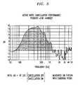
- FIG. 5 is a plot showing active noise-cancellation performance of an illustrative inventive embodiment.
- The noise-cancelling apparatus of the present invention is illustrated in a telephone handset denoted 10 in FIG. 1.
Handset 10 is of basically conventional design and includes a transmitter cap 11 and areceiver cap 12. A quantity ofacoustic blocking foam 13 is disposed in thehandle portion 14 of thehandset 10.Foam 13 may be of a material such as an open pore polyurethane having substantial resilience, good compliance and high acoustic damping properties. Thefoam 13 is a necessary part of the acoustic circuit in order to reduce as much as possible transmission of the user's spoken sound energy from the transmitter portion of the handset to the receiver portion. The foam also suppresses acoustic resonance in the handset interior by effectively controlling the air volume behind the receiver. - As seen in FIGS. 2 and 3, the
receiver cap 12 contains atelephone receiver 15 which is connected bywire 16 to a telephone line 9 of communications network through a noisecancellation control circuit 40.Receiver 15 is contained within aspeaker mounting sleeve 17 which fits snugly into anannular housing 18 of thereceiver cap 12. Receiver cap 12 is fabricated with a slightlydomed earpiece 19 on theexterior surface 20 which contacts the user's ear. A series ofradial slots 21 seen in FIG. 3 provide an acoustic grill through which the incoming signal fromreceiver 15 is passed to the user's ear canal. Theslots 21 also are configured and positioned to pass sound over the shortest possible route from thereceiver 15 to anerror microphone 22 disposed inmicrophone housing 23.- The
microphone housing 23 includes aflange 24 for positioninghousing 23 on earpiece exterior 20, and asleeve 25 within whichmicrophone 22 is fixedly mounted.Housing 23 also includes a series ofsound ports 26 formed through anextension 27 ofhousing 23.Extension 27 is intended to fit and protrude slightly into the user's outer ear to aid in positioning the handset on the user's ear, and to place themicrophone 22 as near to the ear as possible so that it senses the precise sound field which impinges on the user's ear. This degree of fit is needed in order to achieve an optimum noise-cancelling performance over the bandwidth reaching from approximately 100 Hz to 1,000 Hz which is most critical to control for improved speech intelligibility. - Further, as seen in FIGS. 2 and 3,
sound ports 26 in combination withacoustic grill slots 21 form an acoustic path betweenreceiver 15 andmicrophone 22 which is short and direct, and therefore presents relatively little acoustic resistance and phase delay. Minimizing the acoustic resistance betweenreceiver 15 andmicrophone 22 is highly desirable to minimize phase delays between the control signal received bymicrophone 22 and the noise-cancellation signal generated incircuit 40. These signals should have as little phase difference as possible. The juxtaposition as illustrated in FIG. 3 shows thesound ports 26 and the elongateacoustic grill slots 21 as being located with respect to each other in the requisite proximity. - Microphone wires 32 connecting
microphone 22 to thecontrol circuit 40 may be exited fromcavity 29 through apassage 33 formed inannular housing 18. Advantageously, afelt pad 28 is placed between themicrophone 22 and thesound ports 26 to prevent dust or other particles from being introduced through theports 26 onto themicrophone 22. A layer of acoustically transmissive material may be added on top of thepad 28 to further insure against dust and moisture intrusion. Theacoustic slots 21 likewise should not be so open as to permit particulate matter to be introduced therethrough or to allow users to gain entry into the interior ofreceiver cap 12 with paperclips or the like. Aprotective screen 31 advantageously is disposed overreceiver 15.Screen 31 may be a perforated metal disc or grill. Acoustically,screen 31 serves the purpose of transmitting the sound emitted byreceiver 15 without distortion or diminishment. - As seen in FIG. 2,
receiver cap 12 includes acavity 29 into whichfoam 30 is placed. Advantageously, the foam has characteristically open cell structure and is light in weight. A reticulated polyurethane foam is one suitable material.Foam 30 prevents dirt from intruding on thereceiver 15 and also smooths the phase response, by damping undesirable resonant modes and reflections emanating from the enclosure and the user's ear. - The residual phase delay between the noise-cancelling
signal driving receiver 15 and the control signal generated by themicrophone 22, may be predetermined. - The handset design of the present invention produces an electroacoustical transfer function from the speaker input voltage to the microphone output voltage that, with the addition of a low complexity compensation circuit, provides excellent closed loop cancellation performance in the range of from 100 Hz to 1100 Hz. This transfer function, shown in FIG. 4, provides several valuable characteristics. First, it varies gradually with frequency, without erratic or peaked responses. Further, its magnitude rolls off at frequencies above about 1000 Hz such that substantially all resonant peaks above about 2000 Hz are down more than 20 dB from the maximum amplitude. Also, its phase lies between 0 and 360 degrees in the range of from about 100 Hz and in excess of 3000 Hz as seen in the lower curve of FIG. 4. The physical design concepts of the instant invention help achieve these results.
- Importantly, the size and shape of the
slots 21 andports 26 must be controlled to avoid acoustic resonance ofmicrophone 22 and the handset receiver enclosure. The volumes enclosed by themicrophone housing 23 with associatedports 26 andmicrophone 22 comprise a potentially resonant acoustic chamber. Resonant response of this chamber at frequencies within the audible frequency range will introduce amplitude and phase response distortions that degrade the acoustic noise reduction performance. The configuration, diameter and length ofports 26 are selected to reduce this effect. Similar undesired resonant effects are avoided in the handset receiver enclosure through the configuration ofslots 21 which allow passage of sound while preventing access to the speaker. - The utility of the instant invention may be further appreciated by reference to FIG. 5. There, data on noise cancellation vs. frequency taken from an experiment with a single subject, is plotted for the case where the invention is used with a complementary noise cancellation circuit. Noise cancellation may be defined as the ratio of the noise power spectrum, at the user's ear, with the cancellation circuit "off," to the noise power spectrum with the circuit "on" measured in dB. The measurements were made at the subject's eardrum using an Etymotic ear probe together with a spectrum analyzer. FIG. 5 shows cancellation performance from 100 Hz to 1100 Hz with over 10 dB of noise cancellation between 130 Hz and 700 Hz; and up to 15 dB at 400 Hz. This frequency band of cancellation is very effective in the typical noisy environments noted earlier. The level of cancellation is sufficient to make otherwise unintelligible incoming speech understandable.
Claims (8)
- An ambient noise-reducing telephone handset (10) comprising transmitter and receiver ends, transmitter and receiver caps (11,12) respectively disposed on said ends, a receiver (15) mounted in said receiver cap (12), a noise; cancellation microphone (22), a noise-cancellation control circuit (40), and means (32) connecting said microphone (22) to said circuit (40), CHARACTERISED IN THAT said receiver cap (12) comprises an earpiece (19) formed with a central aperture on its exterior surface (20), and a housing (23) mounted through said aperture and extending into the interior of said cap (12) toward said receiver (15), wherein said housing (23) contains said microphone (22)in that part of the housing (23) that is located in the earpiece (19), said housing (23) comprising an outwardly protruding extension (27) which fits into a user's outer ear to position said microphone (22) to directly sample ambient noise in closest proximity to the user's ear canal.
- A handset as claimed in Claim 1 comprising a plurality of radial slots (21) placed around said central aperture through said earpiece (19) defining an acoustic grill through which signals from said receiver (15) are passed substantially directly to the user's ear canal.
- A handset as claimed in claim 2, wherein said housing extension (27) comprises a plurality of sound ports (26), said ports (26) being configured and sized to reduce any resonant response characteristic of said microphone housing (23).
- A handset as claimed in claim 3, comprising an acoustically transmissive pad (28) placed between said microphone (22) and said ports (26) to block particulate matter from entering said receiver cap interior through said ports (26).
- A handset as claimed in claim 4, comprising a layer of acoustically transmissive dust and moisture-impermeable material placed over the exterior-facing surface of said pad (28).
- A handset as claimed in claim 5 comprising an acoustically non-distorting protective screen (31) placed over the exterior-facing side of receiver (15), for passing sound from said receiver (15) with minimum distortion and energy loss.
- A handset as claimed in claim 6 wherein said receiver cap (12) comprises an open cell foam (30) contained in the space between said receiver (15) and said microphone (22), said foam being adapted to damp resonant modes and reflections emanating from or originating in the internal space of said cap (12) and the ear of a user.
- A handset as claimed in claim 6 or 7 wherein said screen (31) is a perforated metal disc.
Applications Claiming Priority (2)
| Application Number | Priority Date | Filing Date | Title |
|---|---|---|---|
| US95417592A | 1992-09-30 | 1992-09-30 | |
| US954175 | 1992-09-30 |
Publications (2)
| Publication Number | Publication Date |
|---|---|
| EP0590869A1 EP0590869A1 (en) | 1994-04-06 |
| EP0590869B1true EP0590869B1 (en) | 1997-12-17 |
Family
ID=25495040
Family Applications (1)
| Application Number | Title | Priority Date | Filing Date |
|---|---|---|---|
| EP93307503AExpired - LifetimeEP0590869B1 (en) | 1992-09-30 | 1993-09-22 | Noise-cancelling telephone handset |
Country Status (8)
| Country | Link |
|---|---|
| US (1) | US5491747A (en) |
| EP (1) | EP0590869B1 (en) |
| JP (1) | JP2795302B2 (en) |
| KR (1) | KR100274913B1 (en) |
| CA (1) | CA2101500C (en) |
| DE (1) | DE69315792T2 (en) |
| ES (1) | ES2110577T3 (en) |
| SG (1) | SG43700A1 (en) |
Families Citing this family (19)
| Publication number | Priority date | Publication date | Assignee | Title |
|---|---|---|---|---|
| JP2609822B2 (en)* | 1994-10-12 | 1997-05-14 | 埼玉日本電気株式会社 | Transmitter |
| DE19513111A1 (en)* | 1995-04-07 | 1996-10-10 | Sennheiser Electronic | Device for reducing noise |
| USD396235S (en) | 1996-10-08 | 1998-07-21 | Tate Joseph B | Noise control aperture |
| US6654467B1 (en) | 1997-05-07 | 2003-11-25 | Stanley J. York | Active noise cancellation apparatus and method |
| US6163610A (en)* | 1998-04-06 | 2000-12-19 | Lucent Technologies Inc. | Telephonic handset apparatus having an earpiece monitor and reduced inter-user variability |
| US7031460B1 (en) | 1998-10-13 | 2006-04-18 | Lucent Technologies Inc. | Telephonic handset employing feed-forward noise cancellation |
| KR20000067321A (en)* | 1999-04-27 | 2000-11-15 | 정완진 | A broadband, acoustical wave shaping and control system of loudspeaker |
| US6285772B1 (en) | 1999-07-20 | 2001-09-04 | Umevoice, Inc. | Noise control device |
| USD428408S (en)* | 1999-07-20 | 2000-07-18 | Ume Voice, Inc. | Element for a noise cancellation device |
| USD427999S (en)* | 1999-07-20 | 2000-07-11 | Umevoice, Inc. | Element for a noise cancellation device |
| USD427998S (en)* | 1999-07-20 | 2000-07-11 | Umevoice, Inc. | Noise cancellation device |
| US6396932B1 (en) | 1999-07-21 | 2002-05-28 | Umevoice, Inc. | Pluggable noise-controlling apparatus and method |
| US6738483B1 (en)* | 1999-10-12 | 2004-05-18 | Sonic Systems, Inc. | Overhead loudspeaker systems |
| USD454344S1 (en) | 2000-10-19 | 2002-03-12 | Ume Voice, Inc. | Noise cancellation device for use with recording devices |
| US7764798B1 (en)* | 2006-07-21 | 2010-07-27 | Cingular Wireless Ii, Llc | Radio frequency interference reduction in connection with mobile phones |
| US7925307B2 (en)* | 2006-10-31 | 2011-04-12 | Palm, Inc. | Audio output using multiple speakers |
| US8311590B2 (en)* | 2006-12-05 | 2012-11-13 | Hewlett-Packard Development Company, L.P. | System and method for improved loudspeaker functionality |
| DE102007001980A1 (en)* | 2007-01-08 | 2008-07-10 | Sennheiser Electronic Gmbh & Co. Kg | headphone |
| EP4033776B1 (en)* | 2019-05-24 | 2025-04-30 | Honeywell International Inc. | Hearing protection devices, noise exposure sensors therefor, and sensor housings and associated methods for the same |
Family Cites Families (12)
| Publication number | Priority date | Publication date | Assignee | Title |
|---|---|---|---|---|
| AT328527B (en)* | 1974-06-12 | 1976-03-25 | Akg Akustische Kino Geraete | DEVICE FOR STEREOPHONIC RECORDING OR CONTROL OF SOUND EVENTS |
| JPS5246803U (en)* | 1975-09-30 | 1977-04-02 | ||
| US4023209A (en)* | 1975-12-17 | 1977-05-17 | Gentex Corporation | Protective helmet assembly with segmental outer shell |
| US4418248A (en)* | 1981-12-11 | 1983-11-29 | Koss Corporation | Dual element headphone |
| US4644581A (en)* | 1985-06-27 | 1987-02-17 | Bose Corporation | Headphone with sound pressure sensing means |
| EP0262915A3 (en)* | 1986-09-30 | 1988-11-30 | Alfred T. Williamson | A combination telephone handset and headset device |
| US4985925A (en)* | 1988-06-24 | 1991-01-15 | Sensor Electronics, Inc. | Active noise reduction system |
| DK161288C (en)* | 1988-10-21 | 1991-12-02 | Alcatel Kirk As | Telephone instrument handset |
| JPH02147993U (en)* | 1989-05-17 | 1990-12-17 | ||
| US5134659A (en)* | 1990-07-10 | 1992-07-28 | Mnc, Inc. | Method and apparatus for performing noise cancelling and headphoning |
| US5305387A (en)* | 1989-10-27 | 1994-04-19 | Bose Corporation | Earphoning |
| US5182774A (en)* | 1990-07-20 | 1993-01-26 | Telex Communications, Inc. | Noise cancellation headset |
- 1993
- 1993-07-28CACA002101500Apatent/CA2101500C/ennot_activeExpired - Fee Related
- 1993-09-22SGSG1995002275Apatent/SG43700A1/enunknown
- 1993-09-22ESES93307503Tpatent/ES2110577T3/ennot_activeExpired - Lifetime
- 1993-09-22EPEP93307503Apatent/EP0590869B1/ennot_activeExpired - Lifetime
- 1993-09-22DEDE69315792Tpatent/DE69315792T2/ennot_activeExpired - Fee Related
- 1993-09-28JPJP5263098Apatent/JP2795302B2/ennot_activeExpired - Fee Related
- 1993-09-28KRKR1019930020219Apatent/KR100274913B1/ennot_activeExpired - Fee Related
- 1994
- 1994-07-25USUS08/279,389patent/US5491747A/ennot_activeExpired - Fee Related
Also Published As
| Publication number | Publication date |
|---|---|
| ES2110577T3 (en) | 1998-02-16 |
| DE69315792D1 (en) | 1998-01-29 |
| JP2795302B2 (en) | 1998-09-10 |
| CA2101500C (en) | 1996-12-17 |
| DE69315792T2 (en) | 1998-04-09 |
| SG43700A1 (en) | 1997-11-14 |
| EP0590869A1 (en) | 1994-04-06 |
| US5491747A (en) | 1996-02-13 |
| CA2101500A1 (en) | 1994-03-31 |
| KR940008333A (en) | 1994-04-29 |
| KR100274913B1 (en) | 2000-12-15 |
| JPH06205092A (en) | 1994-07-22 |
Similar Documents
| Publication | Publication Date | Title |
|---|---|---|
| EP0590869B1 (en) | Noise-cancelling telephone handset | |
| US5343523A (en) | Telephone headset structure for reducing ambient noise | |
| KR100329134B1 (en) | Portable electric device with a speaker assembly | |
| US7245726B2 (en) | Noise canceling microphone system and method for designing the same | |
| US5737433A (en) | Sound environment control apparatus | |
| US5825897A (en) | Noise cancellation apparatus | |
| US4160135A (en) | Closed earphone construction | |
| US5555449A (en) | Extendible antenna and microphone for portable communication unit | |
| EP0906684B1 (en) | Communications terminal having a single transducer for handset and handsfree receive functionality | |
| JP2610632B2 (en) | Method and apparatus for attenuating extrinsic noise reaching the eardrum and improving intelligibility of electroacoustic communication | |
| EP2235966B1 (en) | Microphone device | |
| US20030152240A1 (en) | Method and apperatus for communcation operator privacy | |
| US6058315A (en) | Speaker assembly for a radiotelephone | |
| GB2333927A (en) | Housing for an electro-acoustic transducer, e.g. loudspeaker, earphone, microphone | |
| US6163610A (en) | Telephonic handset apparatus having an earpiece monitor and reduced inter-user variability | |
| CA2094616C (en) | Compact loudspeaker assembly | |
| US20060034476A1 (en) | Headset case arrangement for wind control | |
| KR960701576A (en) | Inductive microphones with multiple unidirectional apertures | |
| JPS6255749B2 (en) | ||
| BRPI9915972B1 (en) | Portable electronic device comprising speech system | |
| KR19990037368U (en) | Sound Tube Portable Cordless Phone |
Legal Events
| Date | Code | Title | Description |
|---|---|---|---|
| PUAI | Public reference made under article 153(3) epc to a published international application that has entered the european phase | Free format text:ORIGINAL CODE: 0009012 | |
| AK | Designated contracting states | Kind code of ref document:A1 Designated state(s):DE ES FR GB | |
| RAP3 | Party data changed (applicant data changed or rights of an application transferred) | Owner name:AT&T CORP. | |
| 17P | Request for examination filed | Effective date:19940921 | |
| 17Q | First examination report despatched | Effective date:19961022 | |
| GRAG | Despatch of communication of intention to grant | Free format text:ORIGINAL CODE: EPIDOS AGRA | |
| GRAG | Despatch of communication of intention to grant | Free format text:ORIGINAL CODE: EPIDOS AGRA | |
| GRAH | Despatch of communication of intention to grant a patent | Free format text:ORIGINAL CODE: EPIDOS IGRA | |
| GRAH | Despatch of communication of intention to grant a patent | Free format text:ORIGINAL CODE: EPIDOS IGRA | |
| GRAA | (expected) grant | Free format text:ORIGINAL CODE: 0009210 | |
| AK | Designated contracting states | Kind code of ref document:B1 Designated state(s):DE ES FR GB | |
| ET | Fr: translation filed | ||
| REF | Corresponds to: | Ref document number:69315792 Country of ref document:DE Date of ref document:19980129 | |
| REG | Reference to a national code | Ref country code:ES Ref legal event code:FG2A Ref document number:2110577 Country of ref document:ES Kind code of ref document:T3 | |
| PLBE | No opposition filed within time limit | Free format text:ORIGINAL CODE: 0009261 | |
| STAA | Information on the status of an ep patent application or granted ep patent | Free format text:STATUS: NO OPPOSITION FILED WITHIN TIME LIMIT | |
| 26N | No opposition filed | ||
| REG | Reference to a national code | Ref country code:GB Ref legal event code:IF02 | |
| PGFP | Annual fee paid to national office [announced via postgrant information from national office to epo] | Ref country code:FR Payment date:20020822 Year of fee payment:10 | |
| PGFP | Annual fee paid to national office [announced via postgrant information from national office to epo] | Ref country code:GB Payment date:20020827 Year of fee payment:10 | |
| PGFP | Annual fee paid to national office [announced via postgrant information from national office to epo] | Ref country code:ES Payment date:20020903 Year of fee payment:10 | |
| PGFP | Annual fee paid to national office [announced via postgrant information from national office to epo] | Ref country code:DE Payment date:20020916 Year of fee payment:10 | |
| PG25 | Lapsed in a contracting state [announced via postgrant information from national office to epo] | Ref country code:GB Free format text:LAPSE BECAUSE OF NON-PAYMENT OF DUE FEES Effective date:20030922 | |
| PG25 | Lapsed in a contracting state [announced via postgrant information from national office to epo] | Ref country code:ES Free format text:LAPSE BECAUSE OF NON-PAYMENT OF DUE FEES Effective date:20030923 | |
| PG25 | Lapsed in a contracting state [announced via postgrant information from national office to epo] | Ref country code:DE Free format text:LAPSE BECAUSE OF NON-PAYMENT OF DUE FEES Effective date:20040401 | |
| GBPC | Gb: european patent ceased through non-payment of renewal fee | Effective date:20030922 | |
| PG25 | Lapsed in a contracting state [announced via postgrant information from national office to epo] | Ref country code:FR Free format text:LAPSE BECAUSE OF NON-PAYMENT OF DUE FEES Effective date:20040528 | |
| REG | Reference to a national code | Ref country code:FR Ref legal event code:ST | |
| REG | Reference to a national code | Ref country code:ES Ref legal event code:FD2A Effective date:20030923 |