EP0589235B1 - Intramedullary nail with locking pin - Google Patents
Intramedullary nail with locking pinDownload PDFInfo
- Publication number
- EP0589235B1 EP0589235B1EP93113711AEP93113711AEP0589235B1EP 0589235 B1EP0589235 B1EP 0589235B1EP 93113711 AEP93113711 AEP 93113711AEP 93113711 AEP93113711 AEP 93113711AEP 0589235 B1EP0589235 B1EP 0589235B1
- Authority
- EP
- European Patent Office
- Prior art keywords
- intramedullary nail
- locking pin
- bone
- bolt
- shank
- Prior art date
- Legal status (The legal status is an assumption and is not a legal conclusion. Google has not performed a legal analysis and makes no representation as to the accuracy of the status listed.)
- Expired - Lifetime
Links
Images
Classifications
- A—HUMAN NECESSITIES
- A61—MEDICAL OR VETERINARY SCIENCE; HYGIENE
- A61B—DIAGNOSIS; SURGERY; IDENTIFICATION
- A61B17/00—Surgical instruments, devices or methods
- A61B17/56—Surgical instruments or methods for treatment of bones or joints; Devices specially adapted therefor
- A61B17/58—Surgical instruments or methods for treatment of bones or joints; Devices specially adapted therefor for osteosynthesis, e.g. bone plates, screws or setting implements
- A61B17/68—Internal fixation devices, including fasteners and spinal fixators, even if a part thereof projects from the skin
- A61B17/80—Cortical plates, i.e. bone plates; Instruments for holding or positioning cortical plates, or for compressing bones attached to cortical plates
Definitions
- the inventiondescribes an intramedullary nail Locking bolt according to the preamble of claim 1.
- a such intramedullary nailis described in AT-B-384 359, wherein with this solution a good hold of the locking bolts is not guaranteed.
- Surgical interventions to correct Bone damageoften becomes screws or special trained nails used to help stabilize, such as B. osteosynthesis plates, joint prostheses, intramedullary nails and the like to connect to the bone or to stabilize bone fragments with each other.
- Typical screws and nails of this typeare e.g. B. in Swiss patents 670 754 and 669 724.
- the screws and nails usedusually have at least a portion of theirs A thread or barb-like formations with which they can prevent any slipping back should be secured.
- This irregular surface shapeleads to problems in many cases. Will such screws and nails are statically or dynamically loaded, this leads to an uneven pressure distribution in the bone tissue. So in the range of Threaded edges and barbs generate high pressure peaks. These can result in absorption, i.e. a breakdown Effect bone material. This leads to a weakening of the bone and a loosening of the screw, respectively. of Nagels, which leads to unfavorable power distribution and breaks in the Bones and in the screw respectively. can lead to the nail.
- the bolt according to the inventionin has essentially smooth surface, in particular no Thread and no barbs, it does not effect uneven pressure distribution in the bone tissue. In order to the resorption of the bone material is prevented.
- the boltcan be used directly without pre-drilling into the bone what the Operation time is significantly reduced and the loss increases Bone material reduced.
- the bolt according to the inventionis also for this suitable, hammered in with a pneumatic impact tool to become.
- a pneumatic impact toolto become.
- Such inserted boltsare characterized by an excellent Stop in the bone.
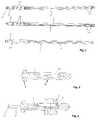
- Figure 1shows an intramedullary nail 3. It points Holes 14 for receiving the shaft of a bolt, which are adapted to its cross-sectional shape.
- the intramedullary nail according to FIG. 1is designed that he was using a pneumatic striking tool can be inserted directly into the bone, as in EP 452 543 is described.
- the intramedullary nailshows 3 a macroscopically essentially smooth surface and a drainage formation 5 for deriving the Bone marrow during the insertion process. This is here in the form of a milled longitudinal channel with drainage channels executed.
- His head 6is also for non-positive Formed connection with the impact tool. To the head 6 has an immediate groove 17 into which the wrapping tool is snapped into place. So that's it resulting connection suitable, both train and To transmit pressure forces.
- the head 6two opposite surfaces 18, one on each corresponding counterpart of the inserted impact instrument is present.
- the intramedullary nailcan thus counteract do not twist the impact instrument.
- the pneumatic striking toolcan avoid damage to the bone even if the intramedullary nail is relatively large Has diameter. This means that intramedullary nails can also be used be in the inserted state on the cortex close fitting.
- the pin 8When inserting the bolt into the bone the pin 8 is not inserted. So that the pressure element lies form-fitting to the shaft wall in the bolt, whereby the bolt as an ordinary inventive Bolt can be driven.
- the position of the Pressure element 9is selected so that it is after insertion comes to rest in the area of the intramedullary nail 3. Becomes now the pin 8 hammered into the hole 7, so he pushes the pressure element outwards against the Intramedullary nail 3. This creates a positive connection made between bolt and intramedullary nail.
- the hitting The pencan also be used with the one already described pneumatic impact tool happen.
Landscapes
- Health & Medical Sciences (AREA)
- Orthopedic Medicine & Surgery (AREA)
- Surgery (AREA)
- Life Sciences & Earth Sciences (AREA)
- Heart & Thoracic Surgery (AREA)
- Animal Behavior & Ethology (AREA)
- Engineering & Computer Science (AREA)
- Biomedical Technology (AREA)
- Neurology (AREA)
- Medical Informatics (AREA)
- Molecular Biology (AREA)
- Nuclear Medicine, Radiotherapy & Molecular Imaging (AREA)
- General Health & Medical Sciences (AREA)
- Public Health (AREA)
- Veterinary Medicine (AREA)
- Surgical Instruments (AREA)
- Transceivers (AREA)
- Mobile Radio Communication Systems (AREA)
Abstract
Description
Translated fromGermanDie Erfindung beschreibt einen Marknagel mitArretierungsbolzen gemäss Oberbegriff von Anspruch 1. Einderartiger Marknagel wird in AT-B-384 359 beschrieben, wobeibei dieser Lösung ein guter Halt der Arretierungsbolzennicht gewährleistet ist.The invention describes an intramedullary nailLocking bolt according to the preamble of
Bei chirurgischen Eingriffen zur Behebung vonKnochenschäden werden oftmals Schrauben oder speziellausgebildete Nägel verwendet, um Stabilisierungshilfen,wie z. B. Osteosyntheseplatten, Gelenkprothesen, Marknägelund dergleichen, mit dem Knochen zu verbinden oderum Knochenfragmente untereinander zu stabilisieren.Typische Schrauben und Nägel dieser Art werden z. B. inden Schweizer Patentschriften 670 754 und 669 724 beschrieben.Surgical interventions to correctBone damage often becomes screws or specialtrained nails used to help stabilize,such as B. osteosynthesis plates, joint prostheses, intramedullary nailsand the like to connect to the bone orto stabilize bone fragments with each other.Typical screws and nails of this type are e.g. B. inSwiss patents 670 754 and 669 724.
Die dabei verwendeten Schrauben und Nägelweisen in der Regel mindestens über einen Teil ihresSchaftes ein Gewinde oder widerhakenartige Ausformungenauf, mit denen sie gegen ein allfälliges Zurückrutschengesichert werden sollen. Diese unregelmässige Oberflächenformführt aber in vielen Fällen zu Problemen. Werdensolche Schrauben und Nägel statisch oder dynamisch belastet,so kommt es zu einer ungleichmässigen Druckverteilungim Knochengewebe. So können im Bereich vonGewindekanten und Widerhaken hohe Druckspitzen entstehen.Diese können eine Resorption, d.h. einen Abbau, desKnochenmaterials bewirken. Dies führt zu einer Schwächungdes Knochens und einer Lockerung der Schraube resp. desNagels, was zu ungünstiger Kraftverteilung und Brüchen imKnochen und in der Schraube resp. dem Nagel führen kann.The screws and nails usedusually have at least a portion of theirsA thread or barb-like formationswith which they can prevent any slipping backshould be secured. This irregular surface shapeleads to problems in many cases. Willsuch screws and nails are statically or dynamically loaded,this leads to an uneven pressure distributionin the bone tissue. So in the range ofThreaded edges and barbs generate high pressure peaks.These can result in absorption, i.e. a breakdownEffect bone material. This leads to a weakeningof the bone and a loosening of the screw, respectively. ofNagels, which leads to unfavorable power distribution and breaks in theBones and in the screw respectively. can lead to the nail.
Wird zum Beispiel eine Schraube durch einenRöhrenknochen geführt und mit ihrem Ende in der dem Kopfgegenüberliegenden Kortikalis verschraubt, so kann derbeschriebene Effekt zu einer Lockerung des verschraubten Endes führen, wodurch zusätzliche Kräfte auf den Kopfbereichder Schraube verlagert werden. Dies kann einenBruch der Schraube oder eine Beschädigung des Knochensim Kopfbereich der Schraube bewirken.For example, if a screw is replaced by aTubular bones guided and with their end in the headopposite cortex screwed, so theeffect described to loosen the screwedEnd up leading to additional forces on the head areathe screw. This can be oneBroken screw or damage to the bonein the head area of the screw.
Auch sind die herkömmlichen Schrauben nichtrotationsstabil, d.h. sie können verdreht und somitgelockert werden, was wiederum zu zusätzlichen Kräftenund zu ungleichmässiger Kraftverteilung und somit zumöglichen Beschädigungen von Schrauben und Knochen führt.Nor are the conventional screwsrotation stable, i.e. they can be twisted and thusbe relaxed, which in turn leads to additional forcesand to uneven power distribution and thus toopossible damage to screws and bones.
In DE-A-39 33 217 wird eine Knochenschienemit Arretierungsbolzen gezeigt, wobei die Arretierungsbolzenspreizbar sind. Solche Bolzen besitzen jedochLängsschlitze, die ebenfalls zu einer ungleichen Kraftverteilungführen können.DE-A-39 33 217 describes a bone splintshown with locking bolts, the locking boltsare spreadable. However, such bolts haveLongitudinal slots that also lead to an uneven distribution of forcebeing able to lead.
Ein weiterer Nachteil herkömmlicher Lösungenliegt darin, dass in der Regel Löcher im Knochen vorgebohrtund oft sogar Gewinde geschnitten werden müssen.Dies bringt einen zusätzlichen Arbeitsgang mit sich, derden Eingriff verteuert. Ausserdem geht dabei Knochenmaterialverloren, was zu einer weiteren Schwächung desKnochens führt.Another disadvantage of conventional solutionsis that holes are usually pre-drilled in the boneand often even have to cut threads.This entails an additional operation, thethe intervention more expensive. Bone material is also involvedlost, further weakening theBone leads.
Deshalb stellt sich die Aufgabe, einen Marknagelmit Arretierungsbolzen der eingangs genannten Artbereitzustellen, der die genannten Nachteile möglichstnicht aufweist und einen guten Halt des Bolzens im Marknagelgewährleistet.Therefore, the task arises, an intramedullary nailwith locking bolts of the type mentionedTo provide the disadvantages mentioned as possibledoes not have and a good hold of the bolt in the intramedullary nailguaranteed.
Diese Aufgabe wird durch den im erstenPatentanspruch beschriebenen Gegenstand gelöst.This task is accomplished by the firstThe object described is solved.
Da der erfindungsgemässe Bolzen eine imwesentlichen glatte Oberfläche hat, die insbesondere keinGewinde und keine Widerhaken aufweist, bewirkt er keineungleichmässige Druckverteilung im Knochengewebe. Damitwird die Resorption des Knochenmaterials verhindert.Since the bolt according to the invention inhas essentially smooth surface, in particular noThread and no barbs, it does not effectuneven pressure distribution in the bone tissue. In order tothe resorption of the bone material is prevented.
Ausserdem kann der Bolzen direkt ohne Vorbohrungin den Knochen eingebracht werden, was dieOperationszeit erheblich verkürzt und den Verlust anKnochenmaterial verkleinert.In addition, the bolt can be used directly without pre-drillinginto the bone what theOperation time is significantly reduced and the loss increasesBone material reduced.
Der erfindungsgemässe Bolzen ist auch dafürgeeignet, mit einem pneumatischen Schlagwerkzeug eingeschlagenzu werden. In diesem Fall wird die Belastungdes Knochens und insbesondere die Gefahr von Knochenrissenwährend des Einschlagens stark verringert. Derarteingebrachte Bolzen zeichnen sich durch einen ausgezeichnetenHalt im Knochen aus.The bolt according to the invention is also for thissuitable, hammered in with a pneumatic impact toolto become. In this case, the burdenof the bone and especially the risk of bone tearsgreatly reduced during impact. Suchinserted bolts are characterized by an excellentStop in the bone.
Weitere Vorteile ergeben sich aus der folgendenBeschreibung anhand der Zeichnungen. Dabei zeigen:
Figur 1 zeigt einen Marknagel 3. Er weistLöcher 14 zur Aufnahme des Schafts eines Bolzens auf,welche dessen Querschnittsform angepasst sind.Figure 1 shows an
Der Marknagel nach Figur 1 ist so ausgestaltet,dass er mit einem pneumatischen Schlagwerkzeugdirekt in den Knochen eingebracht werden kann, wie es inEP 452 543 beschrieben ist. Insbesondere weist der Marknagel3 eine makroskopisch im wesentlichen glatte Oberflächeund eine Abflussausformung 5 zum Ableiten desKnochenmarks beim Einbringvorgang auf. Diese ist hierin Form einer ausgefrästen Längsrinne mit Abflusskanälenausgeführt. Auch ist sein Kopf 6 zur kraftschlüssigenVerbindung mit dem Einschlagwerkzeug ausgeformt. Dazuweist der Kopf 6 eine umgehende Rille 17 auf, in welchedas Einschlagwerkzeug eingerastet wird. Damit ist dieresultierende Verbindung geeignet, sowohl Zug- wie auchDruckkräfte zu übertragen. Ausserdem weist der Kopf 6zwei gegenüberliegende Flächen 18 auf, an denen je einentsprechendes Gegenstück des aufgesetzten Einschlaginstruments anliegt. Somit kann sich der Marknagel gegendas Einschlaginstrument nicht verdrehen.The intramedullary nail according to FIG. 1 is designedthat he was using a pneumatic striking toolcan be inserted directly into the bone, as inEP 452 543 is described. In particular, the intramedullary nail shows3 a macroscopically essentially smooth surfaceand a
Durch eine derartige zug-, stoss- und rotationsfesteVerbindung zwischen Marknagel und Einschlaginstrumentwird die Kontrolle beim Einschlagen undHerausziehen verbessert.By such a tensile, shock and rotation resistantConnection between intramedullary nail and impact instrumentbecomes control when pounding andPulling out improved.
Dank der Verwendung des pneumatischen Schlagwerkzeugeskann eine Beschädigung des Knochens vermiedenwerden, selbst wenn der Marknagel einen relativ grossenDurchmesser aufweist. Somit können auch Marknägel verwendetwerden, die im eingesetzten Zustand an der Kortikaliseng anliegen.Thanks to the use of the pneumatic striking toolcan avoid damage to the boneeven if the intramedullary nail is relatively largeHas diameter. This means that intramedullary nails can also be usedbe in the inserted state on the cortexclose fitting.
Da die Positionierung eines Marknagels undder ihn fixierenden Bolzen (oder herkömmlichen Schrauben)bekanntlich nicht beliebig genau erfolgen kann, ist esnotwendig, dass die Befestigungslöcher 14 des Marknagelsetwas grösser sind als der Schaft der Bolzen. Damit istes möglich, Toleranzen in den Positionierungen derElemente auszugleichen. Allerdings bewirkt dies, dassdie Bolzen nicht oder nur teilweise in kraftschlüssigemKontakt mit dem Marknagel stehen.Because the positioning of an intramedullary nail andthe bolt fixing it (or conventional screws)As is well known, it cannot be done with any accuracynecessary that the mounting
Zur Behebung dieses Problems kann die Ausführungdes erfindungsgemässen Bolzens verwendet werden,die in Figur 2 und 3 gezeigt wird. Dieser Bolzen weisteine Längsbohrung 7 zur Aufnahme eines Stiftes 8 auf.Ausserdem ist ein Teil der Schaftwand durch ein Andruckelement9 ersetzt, das in der Aussparung 10 liegt. DasAndruckelement ist so geformt, dass es zum Teil in dieLängbohrung 7 hineinragt. Wird der Stift 8 in die Längsbohrung7 eingebracht, so drängt er das Ahdruckelementgegen aussen. Dazu ist das Andruckelement elastisch ausgeformtund/oder beweglich gelagert.To resolve this issue, runof the bolt according to the invention are used,which is shown in Figures 2 and 3. This bolt pointsa
Beim Einbringen des Bolzens in den Knochenist der Stift 8 nicht eingesetzt. Damit liegt das Andruckelementformschlüssig zur Schaftwand im Bolzen,wodurch der Bolzen wie ein gewöhnlicher erfindungsgemässerBolzen eingeschlagen werden kann. Die Position des Andruckelements 9 ist so gewählt, dass es nach dem Einbringenim Bereich des Marknagels 3 zu liegen kommt. Wirdjetzt der Stift 8 in die Bohrung 7 eingeschlagen, sodrängt er das Andruckelement nach aussen gegen denMarknagel 3. Somit wird eine kraftschlüssige Verbindungzwischen Bolzen und Marknagel hergestellt. Das Einschlagendes Stifts kann auch mit dem bereits beschriebenenpneumatischen Einschlagwerkzeug geschehen.When inserting the bolt into the bonethe pin 8 is not inserted. So that the pressure element liesform-fitting to the shaft wall in the bolt,whereby the bolt as an ordinary inventiveBolt can be driven. The position of the
Zum Entfernen des Bolzens wird zuerst derStift 8 herausgezogen. Dies kann z.B. mit einer geeignetenZange geschehen, mit welcher sich der Kopf 11 desStifts 8 ergreifen lässt. Mit dem Entfernen des Stifts 8löst sich die Kraft auf das Andruckelement, wodurchdieses sich in den Bolzen zurückzieht und den Bolzenfrei gibt.To remove the bolt, first remove thePulled out pin 8. This can e.g. with a suitable onePliers happen with which the
Claims (3)
- Intramedullary nail with locking pin,wherein the intramedullary nail (3) comprises holes (14)extending transversally to its longitudinal axis for receivingthe at least one locking pin, and wherein thelocking pin comprises a head (1) and a substantially flatshank (2), characterised in that the diameter of theshank (2) of a locking pin received in the intramedullarynail (3) can be increased in at least one transversal directionin at least one section of the shank (2) by manipulationfrom the outside such that the locking pin canbe locked in the intramedullary nail (3), that the lockingpin comprises a longitudinal opening (7) extendingthrough the head (1) and at least through a part of theshank (2), and that the shank (2) of the locking pin comprisesa recess (10) and a pressure member (9) insertedin the recess, wherein a part of the pressure member (9)extends into the longitudinal opening (7) such that byinserting a peg (8) into the longitudinal opening (7) thepressure member (9) can be pushed outwards.
- Intramedullary nail with locking pin ofclaim 1, characterised in that the intramedullary nailcomprises a draining recess (5), a draining hole or adraining slit for draining the marrow.
- Intramedullary nail with locking pin ofone of the preceding claims characterised in that the intramedullarynail comprises a nail head (6) which isshaped such that it can be connected for pulling, pushingand rotation to a driving tool.
Applications Claiming Priority (2)
| Application Number | Priority Date | Filing Date | Title |
|---|---|---|---|
| CH02971/92ACH687229A5 (en) | 1992-09-23 | 1992-09-23 | Pin for insertion into bone tissue. |
| CH2971/92 | 1992-09-23 |
Publications (2)
| Publication Number | Publication Date |
|---|---|
| EP0589235A1 EP0589235A1 (en) | 1994-03-30 |
| EP0589235B1true EP0589235B1 (en) | 1999-06-02 |
Family
ID=4245757
Family Applications (1)
| Application Number | Title | Priority Date | Filing Date |
|---|---|---|---|
| EP93113711AExpired - LifetimeEP0589235B1 (en) | 1992-09-23 | 1993-08-27 | Intramedullary nail with locking pin |
Country Status (8)
| Country | Link |
|---|---|
| US (1) | US5387214A (en) |
| EP (1) | EP0589235B1 (en) |
| JP (1) | JP3331020B2 (en) |
| AT (1) | ATE180651T1 (en) |
| CH (1) | CH687229A5 (en) |
| DE (1) | DE59309623D1 (en) |
| ES (1) | ES2134817T3 (en) |
| GR (1) | GR3031113T3 (en) |
Families Citing this family (7)
| Publication number | Priority date | Publication date | Assignee | Title |
|---|---|---|---|---|
| DE19619093B4 (en)* | 1996-05-06 | 2004-02-26 | Aap Implantate Ag | Intramedullary nail system for fracture healing or bone extension |
| US6187008B1 (en) | 1999-07-07 | 2001-02-13 | Bristol-Myers Squibb | Device for temporarily fixing bones |
| EP1415605B1 (en)* | 2002-11-04 | 2010-10-13 | Zimmer GmbH | Bone fixation system |
| EP1601297B1 (en)* | 2003-03-07 | 2013-07-17 | Synthes GmbH | Locking screw for an intramedullary nail |
| CN1886097B (en)† | 2003-12-19 | 2010-04-28 | 斯恩蒂斯有限公司 | Intramedullary nail |
| US8808292B2 (en)* | 2008-11-11 | 2014-08-19 | Zimmer Gmbh | Orthopedic screw |
| ES2523579T3 (en) | 2010-12-17 | 2014-11-27 | Stryker Trauma Gmbh | Bone fixation and manufacturing procedure |
Family Cites Families (15)
| Publication number | Priority date | Publication date | Assignee | Title |
|---|---|---|---|---|
| FR948690A (en)* | 1947-07-01 | 1949-08-08 | Nail enhancements used for healing fractures of the femoral neck and for blocking the coxofemoral joint | |
| US2490364A (en)* | 1948-02-27 | 1949-12-06 | Herman H Livingston | Bone pin |
| US2627855A (en)* | 1950-04-07 | 1953-02-10 | James W Price | Fracture nail and bone plate |
| CH405600A (en)* | 1963-09-26 | 1966-01-15 | Synthes Ag | Intramedullary nail and the appropriate drive-in and extraction tool |
| US3741205A (en)* | 1971-06-14 | 1973-06-26 | K Markolf | Bone fixation plate |
| US3791380A (en)* | 1971-12-13 | 1974-02-12 | G Dawidowski | Method and apparatus of immobilizing a fractured femur |
| US4103683A (en)* | 1977-06-03 | 1978-08-01 | Neufeld John A | Sub-trochanteric nail |
| GB2084468B (en)* | 1980-09-25 | 1984-06-06 | South African Inventions | Surgical implant |
| AT384359B (en)* | 1981-12-01 | 1987-11-10 | Ender Hans Georg | BONE NAIL |
| DE8528004U1 (en)* | 1985-10-02 | 1986-01-09 | Oswald Leibinger GmbH, 7202 Mühlheim | Bone screw |
| CH669724A5 (en)* | 1986-04-15 | 1989-04-14 | Sulzer Ag | |
| DE3933217A1 (en)* | 1989-10-05 | 1991-04-11 | Gunther Dr Med Dr Rer Hofmann | Biodegradable plastic splint system for bone fractures - has plastic splint, several clasps and two-part bolts which insert into bone and hold splint and clasps in position |
| JPH066810Y2 (en)* | 1989-11-29 | 1994-02-23 | 旭光学工業株式会社 | Vertebral body fixation plate |
| US5057103A (en)* | 1990-05-01 | 1991-10-15 | Davis Emsley A | Compressive intramedullary nail |
| US5085660A (en)* | 1990-11-19 | 1992-02-04 | Lin Kwan C | Innovative locking plate system |
- 1992
- 1992-09-23CHCH02971/92Apatent/CH687229A5/ennot_activeIP Right Cessation
- 1993
- 1993-08-27EPEP93113711Apatent/EP0589235B1/ennot_activeExpired - Lifetime
- 1993-08-27ESES93113711Tpatent/ES2134817T3/ennot_activeExpired - Lifetime
- 1993-08-27ATAT93113711Tpatent/ATE180651T1/ennot_activeIP Right Cessation
- 1993-08-27DEDE59309623Tpatent/DE59309623D1/ennot_activeExpired - Fee Related
- 1993-09-10USUS08/119,612patent/US5387214A/ennot_activeExpired - Fee Related
- 1993-09-16JPJP23011993Apatent/JP3331020B2/ennot_activeExpired - Fee Related
- 1999
- 1999-08-31GRGR990402195Tpatent/GR3031113T3/enunknown
Also Published As
| Publication number | Publication date |
|---|---|
| JPH06178782A (en) | 1994-06-28 |
| US5387214A (en) | 1995-02-07 |
| ATE180651T1 (en) | 1999-06-15 |
| ES2134817T3 (en) | 1999-10-16 |
| DE59309623D1 (en) | 1999-07-08 |
| EP0589235A1 (en) | 1994-03-30 |
| CH687229A5 (en) | 1996-10-31 |
| JP3331020B2 (en) | 2002-10-07 |
| GR3031113T3 (en) | 1999-12-31 |
Similar Documents
| Publication | Publication Date | Title |
|---|---|---|
| EP0654248B1 (en) | Load transfer member for osteosynthesis | |
| EP1096892B1 (en) | Osteosynthesis screw, especially for application by a translaminar vertebral screw | |
| EP1940306B1 (en) | Thread-forming screw | |
| EP0513943B1 (en) | Implant with pressure surface | |
| EP0172130B1 (en) | Screw for orthopaedic fixation | |
| DE69516562T2 (en) | Interference screw with double conical core | |
| DE69430540T2 (en) | TAPERED BONE SCREW WITH VARIOUS THREAD INCLINE | |
| DE19951760B4 (en) | Implant for osteosynthesis | |
| EP0561295B1 (en) | Externally fastened intramedullary nail | |
| DE8900121U1 (en) | Compression screw connection device | |
| EP0209685A2 (en) | Fixation element for osteosynthesis | |
| CH666176A5 (en) | DEVICE FOR TREATING A BONE AND NAIL FOR SUCH A DEVICE. | |
| DE2807364A1 (en) | BONE SCREW | |
| EP0736286A2 (en) | Osteosynthetic device for treating subtrochanteric and pertrochanteric fractures and fractures of the neck of the femur | |
| WO2014184175A1 (en) | Osteosynthesis plate and system for osteosynthesis | |
| DE20113345U1 (en) | Femurfrakturnagel | |
| EP0589235B1 (en) | Intramedullary nail with locking pin | |
| EP1214914B1 (en) | Locking screw for implants | |
| DE2542263A1 (en) | Osteo synthetic pin for bone fractures - has slotted ends which are expanded by screwed spindle | |
| DE3538238A1 (en) | Osteosynthesis fixing element | |
| WO2008129401A1 (en) | Compression screw comprising a wire element | |
| DE3413596C2 (en) | Intramedullary locking nail | |
| WO2003053265A1 (en) | Modular bone nail | |
| DE19913770B4 (en) | bone screw | |
| AT403543B (en) | Device for treating femoral neck fractures |
Legal Events
| Date | Code | Title | Description |
|---|---|---|---|
| PUAI | Public reference made under article 153(3) epc to a published international application that has entered the european phase | Free format text:ORIGINAL CODE: 0009012 | |
| AK | Designated contracting states | Kind code of ref document:A1 Designated state(s):AT BE CH DE DK ES FR GB GR IE IT LI LU MC NL PT SE | |
| 17P | Request for examination filed | Effective date:19940912 | |
| RAP3 | Party data changed (applicant data changed or rights of an application transferred) | Owner name:GEISSER, ALBERT Owner name:KROPF, PHILIPP ROLF | |
| 17Q | First examination report despatched | Effective date:19970324 | |
| GRAG | Despatch of communication of intention to grant | Free format text:ORIGINAL CODE: EPIDOS AGRA | |
| GRAG | Despatch of communication of intention to grant | Free format text:ORIGINAL CODE: EPIDOS AGRA | |
| GRAG | Despatch of communication of intention to grant | Free format text:ORIGINAL CODE: EPIDOS AGRA | |
| GRAH | Despatch of communication of intention to grant a patent | Free format text:ORIGINAL CODE: EPIDOS IGRA | |
| GRAH | Despatch of communication of intention to grant a patent | Free format text:ORIGINAL CODE: EPIDOS IGRA | |
| GRAA | (expected) grant | Free format text:ORIGINAL CODE: 0009210 | |
| AK | Designated contracting states | Kind code of ref document:B1 Designated state(s):AT BE CH DE DK ES FR GB GR IE IT LI LU MC NL PT SE | |
| REF | Corresponds to: | Ref document number:180651 Country of ref document:AT Date of ref document:19990615 Kind code of ref document:T | |
| REG | Reference to a national code | Ref country code:CH Ref legal event code:EP | |
| REF | Corresponds to: | Ref document number:59309623 Country of ref document:DE Date of ref document:19990708 | |
| REG | Reference to a national code | Ref country code:IE Ref legal event code:FG4D Free format text:GERMAN | |
| ITF | It: translation for a ep patent filed | ||
| PG25 | Lapsed in a contracting state [announced via postgrant information from national office to epo] | Ref country code:LU Free format text:LAPSE BECAUSE OF NON-PAYMENT OF DUE FEES Effective date:19990827 Ref country code:IE Free format text:LAPSE BECAUSE OF NON-PAYMENT OF DUE FEES Effective date:19990827 | |
| REG | Reference to a national code | Ref country code:CH Ref legal event code:NV Representative=s name:E. BLUM & CO. PATENTANWAELTE | |
| PG25 | Lapsed in a contracting state [announced via postgrant information from national office to epo] | Ref country code:PT Free format text:LAPSE BECAUSE OF FAILURE TO SUBMIT A TRANSLATION OF THE DESCRIPTION OR TO PAY THE FEE WITHIN THE PRESCRIBED TIME-LIMIT Effective date:19990902 Ref country code:DK Free format text:LAPSE BECAUSE OF FAILURE TO SUBMIT A TRANSLATION OF THE DESCRIPTION OR TO PAY THE FEE WITHIN THE PRESCRIBED TIME-LIMIT Effective date:19990902 | |
| GBT | Gb: translation of ep patent filed (gb section 77(6)(a)/1977) | Effective date:19990819 | |
| ET | Fr: translation filed | ||
| REG | Reference to a national code | Ref country code:ES Ref legal event code:FG2A Ref document number:2134817 Country of ref document:ES Kind code of ref document:T3 | |
| PG25 | Lapsed in a contracting state [announced via postgrant information from national office to epo] | Ref country code:MC Free format text:LAPSE BECAUSE OF NON-PAYMENT OF DUE FEES Effective date:20000229 | |
| PLBE | No opposition filed within time limit | Free format text:ORIGINAL CODE: 0009261 | |
| 26N | No opposition filed | ||
| REG | Reference to a national code | Ref country code:IE Ref legal event code:MM4A | |
| REG | Reference to a national code | Ref country code:GB Ref legal event code:IF02 | |
| PGFP | Annual fee paid to national office [announced via postgrant information from national office to epo] | Ref country code:SE Payment date:20020701 Year of fee payment:10 | |
| PGFP | Annual fee paid to national office [announced via postgrant information from national office to epo] | Ref country code:GB Payment date:20020704 Year of fee payment:10 | |
| PGFP | Annual fee paid to national office [announced via postgrant information from national office to epo] | Ref country code:GR Payment date:20020708 Year of fee payment:10 | |
| PGFP | Annual fee paid to national office [announced via postgrant information from national office to epo] | Ref country code:CH Payment date:20020711 Year of fee payment:10 | |
| PGFP | Annual fee paid to national office [announced via postgrant information from national office to epo] | Ref country code:ES Payment date:20020730 Year of fee payment:10 | |
| PGFP | Annual fee paid to national office [announced via postgrant information from national office to epo] | Ref country code:AT Payment date:20020809 Year of fee payment:10 | |
| PGFP | Annual fee paid to national office [announced via postgrant information from national office to epo] | Ref country code:FR Payment date:20020828 Year of fee payment:10 | |
| PGFP | Annual fee paid to national office [announced via postgrant information from national office to epo] | Ref country code:NL Payment date:20020830 Year of fee payment:10 | |
| PGFP | Annual fee paid to national office [announced via postgrant information from national office to epo] | Ref country code:BE Payment date:20020930 Year of fee payment:10 | |
| PG25 | Lapsed in a contracting state [announced via postgrant information from national office to epo] | Ref country code:GB Free format text:LAPSE BECAUSE OF NON-PAYMENT OF DUE FEES Effective date:20030827 Ref country code:AT Free format text:LAPSE BECAUSE OF NON-PAYMENT OF DUE FEES Effective date:20030827 | |
| PG25 | Lapsed in a contracting state [announced via postgrant information from national office to epo] | Ref country code:SE Free format text:LAPSE BECAUSE OF NON-PAYMENT OF DUE FEES Effective date:20030828 Ref country code:ES Free format text:LAPSE BECAUSE OF NON-PAYMENT OF DUE FEES Effective date:20030828 | |
| PG25 | Lapsed in a contracting state [announced via postgrant information from national office to epo] | Ref country code:LI Free format text:LAPSE BECAUSE OF NON-PAYMENT OF DUE FEES Effective date:20030831 Ref country code:CH Free format text:LAPSE BECAUSE OF NON-PAYMENT OF DUE FEES Effective date:20030831 Ref country code:BE Free format text:LAPSE BECAUSE OF NON-PAYMENT OF DUE FEES Effective date:20030831 | |
| BERE | Be: lapsed | Owner name:*GEISSER ALBERT Effective date:20030831 Owner name:*KROPF PHILIPP ROLF Effective date:20030831 | |
| PG25 | Lapsed in a contracting state [announced via postgrant information from national office to epo] | Ref country code:NL Free format text:LAPSE BECAUSE OF NON-PAYMENT OF DUE FEES Effective date:20040301 | |
| PG25 | Lapsed in a contracting state [announced via postgrant information from national office to epo] | Ref country code:GR Free format text:LAPSE BECAUSE OF NON-PAYMENT OF DUE FEES Effective date:20040303 | |
| EUG | Se: european patent has lapsed | ||
| REG | Reference to a national code | Ref country code:CH Ref legal event code:PL | |
| GBPC | Gb: european patent ceased through non-payment of renewal fee | ||
| PG25 | Lapsed in a contracting state [announced via postgrant information from national office to epo] | Ref country code:FR Free format text:LAPSE BECAUSE OF NON-PAYMENT OF DUE FEES Effective date:20040430 | |
| NLV4 | Nl: lapsed or anulled due to non-payment of the annual fee | Effective date:20040301 | |
| REG | Reference to a national code | Ref country code:FR Ref legal event code:ST | |
| PGFP | Annual fee paid to national office [announced via postgrant information from national office to epo] | Ref country code:DE Payment date:20040805 Year of fee payment:12 | |
| REG | Reference to a national code | Ref country code:ES Ref legal event code:FD2A Effective date:20030828 | |
| PG25 | Lapsed in a contracting state [announced via postgrant information from national office to epo] | Ref country code:IT Free format text:LAPSE BECAUSE OF NON-PAYMENT OF DUE FEES;WARNING: LAPSES OF ITALIAN PATENTS WITH EFFECTIVE DATE BEFORE 2007 MAY HAVE OCCURRED AT ANY TIME BEFORE 2007. THE CORRECT EFFECTIVE DATE MAY BE DIFFERENT FROM THE ONE RECORDED. Effective date:20050827 | |
| PG25 | Lapsed in a contracting state [announced via postgrant information from national office to epo] | Ref country code:DE Free format text:LAPSE BECAUSE OF NON-PAYMENT OF DUE FEES Effective date:20060301 |