EP0588501B1 - Technique for enhancing adhesion capability of heat spreaders in molded packages - Google Patents
Technique for enhancing adhesion capability of heat spreaders in molded packagesDownload PDFInfo
- Publication number
- EP0588501B1 EP0588501B1EP93306511AEP93306511AEP0588501B1EP 0588501 B1EP0588501 B1EP 0588501B1EP 93306511 AEP93306511 AEP 93306511AEP 93306511 AEP93306511 AEP 93306511AEP 0588501 B1EP0588501 B1EP 0588501B1
- Authority
- EP
- European Patent Office
- Prior art keywords
- electrical circuit
- coating
- heat spreader
- package
- metal
- Prior art date
- Legal status (The legal status is an assumption and is not a legal conclusion. Google has not performed a legal analysis and makes no representation as to the accuracy of the status listed.)
- Expired - Lifetime
Links
- 238000000034methodMethods0.000titleclaimsdescription13
- 230000002708enhancing effectEffects0.000titleclaimsdescription9
- 238000000576coating methodMethods0.000claimsdescription79
- 239000011248coating agentSubstances0.000claimsdescription69
- 238000000465mouldingMethods0.000claimsdescription36
- 229910052751metalInorganic materials0.000claimsdescription35
- 239000002184metalSubstances0.000claimsdescription35
- 239000000853adhesiveSubstances0.000claimsdescription31
- 230000001070adhesive effectEffects0.000claimsdescription31
- 239000000463materialSubstances0.000claimsdescription30
- NPXOKRUENSOPAO-UHFFFAOYSA-NRaney nickelChemical compound[Al].[Ni]NPXOKRUENSOPAO-UHFFFAOYSA-N0.000claimsdescription27
- 229910000907nickel aluminideInorganic materials0.000claimsdescription26
- 150000001875compoundsChemical class0.000claimsdescription18
- 239000004065semiconductorSubstances0.000claimsdescription15
- 230000008021depositionEffects0.000claimsdescription10
- 239000007921spraySubstances0.000claimsdescription4
- 238000004519manufacturing processMethods0.000claimsdescription2
- 238000010137moulding (plastic)Methods0.000claimsdescription2
- 239000000206moulding compoundSubstances0.000claimsdescription2
- 238000009718spray depositionMethods0.000claims1
- IWZSHWBGHQBIML-ZGGLMWTQSA-N(3S,8S,10R,13S,14S,17S)-17-isoquinolin-7-yl-N,N,10,13-tetramethyl-2,3,4,7,8,9,11,12,14,15,16,17-dodecahydro-1H-cyclopenta[a]phenanthren-3-amineChemical compoundCN(C)[C@H]1CC[C@]2(C)C3CC[C@@]4(C)[C@@H](CC[C@@H]4c4ccc5ccncc5c4)[C@@H]3CC=C2C1IWZSHWBGHQBIML-ZGGLMWTQSA-N0.000description15
- PNEYBMLMFCGWSK-UHFFFAOYSA-NAluminaChemical compound[O-2].[O-2].[O-2].[Al+3].[Al+3]PNEYBMLMFCGWSK-UHFFFAOYSA-N0.000description15
- 238000000151depositionMethods0.000description9
- 239000010410layerSubstances0.000description9
- 230000032798delaminationEffects0.000description8
- 238000005336crackingMethods0.000description7
- 238000009501film coatingMethods0.000description6
- 229940126639Compound 33Drugs0.000description5
- PNUZDKCDAWUEGK-CYZMBNFOSA-NSitafloxacinChemical compoundC([C@H]1N)N(C=2C(=C3C(C(C(C(O)=O)=CN3[C@H]3[C@H](C3)F)=O)=CC=2F)Cl)CC11CC1PNUZDKCDAWUEGK-CYZMBNFOSA-N0.000description5
- 239000007888film coatingSubstances0.000description5
- 230000001965increasing effectEffects0.000description5
- 238000005137deposition processMethods0.000description4
- 239000007789gasSubstances0.000description4
- 238000005476solderingMethods0.000description4
- RYGMFSIKBFXOCR-UHFFFAOYSA-NCopperChemical compound[Cu]RYGMFSIKBFXOCR-UHFFFAOYSA-N0.000description3
- 229910052802copperInorganic materials0.000description3
- 239000010949copperSubstances0.000description3
- 229920006332epoxy adhesivePolymers0.000description3
- 238000004806packaging method and processMethods0.000description3
- 230000002093peripheral effectEffects0.000description3
- XKRFYHLGVUSROY-UHFFFAOYSA-NArgonChemical compound[Ar]XKRFYHLGVUSROY-UHFFFAOYSA-N0.000description2
- IJGRMHOSHXDMSA-UHFFFAOYSA-NAtomic nitrogenChemical compoundN#NIJGRMHOSHXDMSA-UHFFFAOYSA-N0.000description2
- 239000004593EpoxySubstances0.000description2
- 239000012790adhesive layerSubstances0.000description2
- 229910052782aluminiumInorganic materials0.000description2
- XAGFODPZIPBFFR-UHFFFAOYSA-NaluminiumChemical compound[Al]XAGFODPZIPBFFR-UHFFFAOYSA-N0.000description2
- 238000005516engineering processMethods0.000description2
- 239000010408filmSubstances0.000description2
- 230000000873masking effectEffects0.000description2
- 239000006082mold release agentSubstances0.000description2
- 229920003986novolacPolymers0.000description2
- 239000004033plasticSubstances0.000description2
- 238000002203pretreatmentMethods0.000description2
- 230000000717retained effectEffects0.000description2
- 238000005507sprayingMethods0.000description2
- 238000005299abrasionMethods0.000description1
- 229910052786argonInorganic materials0.000description1
- 239000000919ceramicSubstances0.000description1
- 239000003795chemical substances by applicationSubstances0.000description1
- 239000004020conductorSubstances0.000description1
- 230000001351cycling effectEffects0.000description1
- 230000008030eliminationEffects0.000description1
- 238000003379elimination reactionMethods0.000description1
- 239000008393encapsulating agentSubstances0.000description1
- -1for exampleSubstances0.000description1
- 238000002955isolationMethods0.000description1
- 229910044991metal oxideInorganic materials0.000description1
- 150000004706metal oxidesChemical class0.000description1
- 238000000386microscopyMethods0.000description1
- 229910052757nitrogenInorganic materials0.000description1
- 230000035515penetrationEffects0.000description1
- 239000000758substrateSubstances0.000description1
- 239000010409thin filmSubstances0.000description1
- XLYOFNOQVPJJNP-UHFFFAOYSA-NwaterSubstancesOXLYOFNOQVPJJNP-UHFFFAOYSA-N0.000description1
Images

Classifications
- H—ELECTRICITY
- H01—ELECTRIC ELEMENTS
- H01L—SEMICONDUCTOR DEVICES NOT COVERED BY CLASS H10
- H01L24/00—Arrangements for connecting or disconnecting semiconductor or solid-state bodies; Methods or apparatus related thereto
- H01L24/01—Means for bonding being attached to, or being formed on, the surface to be connected, e.g. chip-to-package, die-attach, "first-level" interconnects; Manufacturing methods related thereto
- H01L24/26—Layer connectors, e.g. plate connectors, solder or adhesive layers; Manufacturing methods related thereto
- H01L24/31—Structure, shape, material or disposition of the layer connectors after the connecting process
- H01L24/32—Structure, shape, material or disposition of the layer connectors after the connecting process of an individual layer connector
- H—ELECTRICITY
- H01—ELECTRIC ELEMENTS
- H01L—SEMICONDUCTOR DEVICES NOT COVERED BY CLASS H10
- H01L21/00—Processes or apparatus adapted for the manufacture or treatment of semiconductor or solid state devices or of parts thereof
- H01L21/02—Manufacture or treatment of semiconductor devices or of parts thereof
- H01L21/04—Manufacture or treatment of semiconductor devices or of parts thereof the devices having potential barriers, e.g. a PN junction, depletion layer or carrier concentration layer
- H01L21/48—Manufacture or treatment of parts, e.g. containers, prior to assembly of the devices, using processes not provided for in a single one of the groups H01L21/18 - H01L21/326 or H10D48/04 - H10D48/07
- H01L21/4814—Conductive parts
- H01L21/4871—Bases, plates or heatsinks
- H—ELECTRICITY
- H01—ELECTRIC ELEMENTS
- H01L—SEMICONDUCTOR DEVICES NOT COVERED BY CLASS H10
- H01L23/00—Details of semiconductor or other solid state devices
- H01L23/02—Containers; Seals
- H01L23/04—Containers; Seals characterised by the shape of the container or parts, e.g. caps, walls
- H—ELECTRICITY
- H01—ELECTRIC ELEMENTS
- H01L—SEMICONDUCTOR DEVICES NOT COVERED BY CLASS H10
- H01L23/00—Details of semiconductor or other solid state devices
- H01L23/02—Containers; Seals
- H01L23/10—Containers; Seals characterised by the material or arrangement of seals between parts, e.g. between cap and base of the container or between leads and walls of the container
- H—ELECTRICITY
- H01—ELECTRIC ELEMENTS
- H01L—SEMICONDUCTOR DEVICES NOT COVERED BY CLASS H10
- H01L23/00—Details of semiconductor or other solid state devices
- H01L23/34—Arrangements for cooling, heating, ventilating or temperature compensation ; Temperature sensing arrangements
- H01L23/36—Selection of materials, or shaping, to facilitate cooling or heating, e.g. heatsinks
- H01L23/373—Cooling facilitated by selection of materials for the device or materials for thermal expansion adaptation, e.g. carbon
- H01L23/3731—Ceramic materials or glass
- H—ELECTRICITY
- H01—ELECTRIC ELEMENTS
- H01L—SEMICONDUCTOR DEVICES NOT COVERED BY CLASS H10
- H01L23/00—Details of semiconductor or other solid state devices
- H01L23/34—Arrangements for cooling, heating, ventilating or temperature compensation ; Temperature sensing arrangements
- H01L23/42—Fillings or auxiliary members in containers or encapsulations selected or arranged to facilitate heating or cooling
- H01L23/433—Auxiliary members in containers characterised by their shape, e.g. pistons
- H01L23/4334—Auxiliary members in encapsulations
- H—ELECTRICITY
- H01—ELECTRIC ELEMENTS
- H01L—SEMICONDUCTOR DEVICES NOT COVERED BY CLASS H10
- H01L2224/00—Indexing scheme for arrangements for connecting or disconnecting semiconductor or solid-state bodies and methods related thereto as covered by H01L24/00
- H01L2224/01—Means for bonding being attached to, or being formed on, the surface to be connected, e.g. chip-to-package, die-attach, "first-level" interconnects; Manufacturing methods related thereto
- H01L2224/26—Layer connectors, e.g. plate connectors, solder or adhesive layers; Manufacturing methods related thereto
- H01L2224/2612—Auxiliary members for layer connectors, e.g. spacers
- H—ELECTRICITY
- H01—ELECTRIC ELEMENTS
- H01L—SEMICONDUCTOR DEVICES NOT COVERED BY CLASS H10
- H01L2224/00—Indexing scheme for arrangements for connecting or disconnecting semiconductor or solid-state bodies and methods related thereto as covered by H01L24/00
- H01L2224/01—Means for bonding being attached to, or being formed on, the surface to be connected, e.g. chip-to-package, die-attach, "first-level" interconnects; Manufacturing methods related thereto
- H01L2224/26—Layer connectors, e.g. plate connectors, solder or adhesive layers; Manufacturing methods related thereto
- H01L2224/31—Structure, shape, material or disposition of the layer connectors after the connecting process
- H01L2224/32—Structure, shape, material or disposition of the layer connectors after the connecting process of an individual layer connector
- H01L2224/321—Disposition
- H01L2224/32151—Disposition the layer connector connecting between a semiconductor or solid-state body and an item not being a semiconductor or solid-state body, e.g. chip-to-substrate, chip-to-passive
- H01L2224/32221—Disposition the layer connector connecting between a semiconductor or solid-state body and an item not being a semiconductor or solid-state body, e.g. chip-to-substrate, chip-to-passive the body and the item being stacked
- H01L2224/32245—Disposition the layer connector connecting between a semiconductor or solid-state body and an item not being a semiconductor or solid-state body, e.g. chip-to-substrate, chip-to-passive the body and the item being stacked the item being metallic
- H—ELECTRICITY
- H01—ELECTRIC ELEMENTS
- H01L—SEMICONDUCTOR DEVICES NOT COVERED BY CLASS H10
- H01L2224/00—Indexing scheme for arrangements for connecting or disconnecting semiconductor or solid-state bodies and methods related thereto as covered by H01L24/00
- H01L2224/01—Means for bonding being attached to, or being formed on, the surface to be connected, e.g. chip-to-package, die-attach, "first-level" interconnects; Manufacturing methods related thereto
- H01L2224/42—Wire connectors; Manufacturing methods related thereto
- H01L2224/47—Structure, shape, material or disposition of the wire connectors after the connecting process
- H01L2224/48—Structure, shape, material or disposition of the wire connectors after the connecting process of an individual wire connector
- H01L2224/4805—Shape
- H01L2224/4809—Loop shape
- H01L2224/48091—Arched
- H—ELECTRICITY
- H01—ELECTRIC ELEMENTS
- H01L—SEMICONDUCTOR DEVICES NOT COVERED BY CLASS H10
- H01L2224/00—Indexing scheme for arrangements for connecting or disconnecting semiconductor or solid-state bodies and methods related thereto as covered by H01L24/00
- H01L2224/01—Means for bonding being attached to, or being formed on, the surface to be connected, e.g. chip-to-package, die-attach, "first-level" interconnects; Manufacturing methods related thereto
- H01L2224/42—Wire connectors; Manufacturing methods related thereto
- H01L2224/47—Structure, shape, material or disposition of the wire connectors after the connecting process
- H01L2224/48—Structure, shape, material or disposition of the wire connectors after the connecting process of an individual wire connector
- H01L2224/481—Disposition
- H01L2224/48151—Connecting between a semiconductor or solid-state body and an item not being a semiconductor or solid-state body, e.g. chip-to-substrate, chip-to-passive
- H01L2224/48221—Connecting between a semiconductor or solid-state body and an item not being a semiconductor or solid-state body, e.g. chip-to-substrate, chip-to-passive the body and the item being stacked
- H01L2224/48245—Connecting between a semiconductor or solid-state body and an item not being a semiconductor or solid-state body, e.g. chip-to-substrate, chip-to-passive the body and the item being stacked the item being metallic
- H01L2224/48247—Connecting between a semiconductor or solid-state body and an item not being a semiconductor or solid-state body, e.g. chip-to-substrate, chip-to-passive the body and the item being stacked the item being metallic connecting the wire to a bond pad of the item
- H—ELECTRICITY
- H01—ELECTRIC ELEMENTS
- H01L—SEMICONDUCTOR DEVICES NOT COVERED BY CLASS H10
- H01L2224/00—Indexing scheme for arrangements for connecting or disconnecting semiconductor or solid-state bodies and methods related thereto as covered by H01L24/00
- H01L2224/01—Means for bonding being attached to, or being formed on, the surface to be connected, e.g. chip-to-package, die-attach, "first-level" interconnects; Manufacturing methods related thereto
- H01L2224/42—Wire connectors; Manufacturing methods related thereto
- H01L2224/47—Structure, shape, material or disposition of the wire connectors after the connecting process
- H01L2224/48—Structure, shape, material or disposition of the wire connectors after the connecting process of an individual wire connector
- H01L2224/484—Connecting portions
- H01L2224/48463—Connecting portions the connecting portion on the bonding area of the semiconductor or solid-state body being a ball bond
- H01L2224/48465—Connecting portions the connecting portion on the bonding area of the semiconductor or solid-state body being a ball bond the other connecting portion not on the bonding area being a wedge bond, i.e. ball-to-wedge, regular stitch
- H—ELECTRICITY
- H01—ELECTRIC ELEMENTS
- H01L—SEMICONDUCTOR DEVICES NOT COVERED BY CLASS H10
- H01L2224/00—Indexing scheme for arrangements for connecting or disconnecting semiconductor or solid-state bodies and methods related thereto as covered by H01L24/00
- H01L2224/73—Means for bonding being of different types provided for in two or more of groups H01L2224/10, H01L2224/18, H01L2224/26, H01L2224/34, H01L2224/42, H01L2224/50, H01L2224/63, H01L2224/71
- H01L2224/732—Location after the connecting process
- H01L2224/73251—Location after the connecting process on different surfaces
- H01L2224/73265—Layer and wire connectors
- H—ELECTRICITY
- H01—ELECTRIC ELEMENTS
- H01L—SEMICONDUCTOR DEVICES NOT COVERED BY CLASS H10
- H01L24/00—Arrangements for connecting or disconnecting semiconductor or solid-state bodies; Methods or apparatus related thereto
- H01L24/01—Means for bonding being attached to, or being formed on, the surface to be connected, e.g. chip-to-package, die-attach, "first-level" interconnects; Manufacturing methods related thereto
- H01L24/42—Wire connectors; Manufacturing methods related thereto
- H01L24/47—Structure, shape, material or disposition of the wire connectors after the connecting process
- H01L24/48—Structure, shape, material or disposition of the wire connectors after the connecting process of an individual wire connector
- H—ELECTRICITY
- H01—ELECTRIC ELEMENTS
- H01L—SEMICONDUCTOR DEVICES NOT COVERED BY CLASS H10
- H01L2924/00—Indexing scheme for arrangements or methods for connecting or disconnecting semiconductor or solid-state bodies as covered by H01L24/00
- H01L2924/0001—Technical content checked by a classifier
- H01L2924/00014—Technical content checked by a classifier the subject-matter covered by the group, the symbol of which is combined with the symbol of this group, being disclosed without further technical details
- H—ELECTRICITY
- H01—ELECTRIC ELEMENTS
- H01L—SEMICONDUCTOR DEVICES NOT COVERED BY CLASS H10
- H01L2924/00—Indexing scheme for arrangements or methods for connecting or disconnecting semiconductor or solid-state bodies as covered by H01L24/00
- H01L2924/01—Chemical elements
- H01L2924/01005—Boron [B]
- H—ELECTRICITY
- H01—ELECTRIC ELEMENTS
- H01L—SEMICONDUCTOR DEVICES NOT COVERED BY CLASS H10
- H01L2924/00—Indexing scheme for arrangements or methods for connecting or disconnecting semiconductor or solid-state bodies as covered by H01L24/00
- H01L2924/01—Chemical elements
- H01L2924/01006—Carbon [C]
- H—ELECTRICITY
- H01—ELECTRIC ELEMENTS
- H01L—SEMICONDUCTOR DEVICES NOT COVERED BY CLASS H10
- H01L2924/00—Indexing scheme for arrangements or methods for connecting or disconnecting semiconductor or solid-state bodies as covered by H01L24/00
- H01L2924/01—Chemical elements
- H01L2924/01013—Aluminum [Al]
- H—ELECTRICITY
- H01—ELECTRIC ELEMENTS
- H01L—SEMICONDUCTOR DEVICES NOT COVERED BY CLASS H10
- H01L2924/00—Indexing scheme for arrangements or methods for connecting or disconnecting semiconductor or solid-state bodies as covered by H01L24/00
- H01L2924/01—Chemical elements
- H01L2924/01018—Argon [Ar]
- H—ELECTRICITY
- H01—ELECTRIC ELEMENTS
- H01L—SEMICONDUCTOR DEVICES NOT COVERED BY CLASS H10
- H01L2924/00—Indexing scheme for arrangements or methods for connecting or disconnecting semiconductor or solid-state bodies as covered by H01L24/00
- H01L2924/01—Chemical elements
- H01L2924/01029—Copper [Cu]
- H—ELECTRICITY
- H01—ELECTRIC ELEMENTS
- H01L—SEMICONDUCTOR DEVICES NOT COVERED BY CLASS H10
- H01L2924/00—Indexing scheme for arrangements or methods for connecting or disconnecting semiconductor or solid-state bodies as covered by H01L24/00
- H01L2924/01—Chemical elements
- H01L2924/01033—Arsenic [As]
- H—ELECTRICITY
- H01—ELECTRIC ELEMENTS
- H01L—SEMICONDUCTOR DEVICES NOT COVERED BY CLASS H10
- H01L2924/00—Indexing scheme for arrangements or methods for connecting or disconnecting semiconductor or solid-state bodies as covered by H01L24/00
- H01L2924/01—Chemical elements
- H01L2924/01082—Lead [Pb]
- H—ELECTRICITY
- H01—ELECTRIC ELEMENTS
- H01L—SEMICONDUCTOR DEVICES NOT COVERED BY CLASS H10
- H01L2924/00—Indexing scheme for arrangements or methods for connecting or disconnecting semiconductor or solid-state bodies as covered by H01L24/00
- H01L2924/10—Details of semiconductor or other solid state devices to be connected
- H01L2924/11—Device type
- H01L2924/14—Integrated circuits
- H—ELECTRICITY
- H01—ELECTRIC ELEMENTS
- H01L—SEMICONDUCTOR DEVICES NOT COVERED BY CLASS H10
- H01L2924/00—Indexing scheme for arrangements or methods for connecting or disconnecting semiconductor or solid-state bodies as covered by H01L24/00
- H01L2924/15—Details of package parts other than the semiconductor or other solid state devices to be connected
- H01L2924/181—Encapsulation
- H—ELECTRICITY
- H01—ELECTRIC ELEMENTS
- H01L—SEMICONDUCTOR DEVICES NOT COVERED BY CLASS H10
- H01L2924/00—Indexing scheme for arrangements or methods for connecting or disconnecting semiconductor or solid-state bodies as covered by H01L24/00
- H01L2924/30—Technical effects
- H01L2924/301—Electrical effects
- H01L2924/3011—Impedance
Definitions
- This inventionrelates generally to molded packages such as those used in integrated circuit packaging and, more particularly, to a packaging technique which reduces the likelihood of delamination and package cracking by enhancing the adhesion between the molding compound and the heat spreader within such packages.
- Integrated circuit chipsare being fabricated with ever smaller geometries and higher circuit densities.
- the power consumption associated with these increased circuit densitieshas also increased, thereby increasing the thermal transport requirements of the package.
- the integrated circuit chipis supported on a metal or ceramic heat spreader.
- the chip and heat spreaderare overmolded by a plastic molding compound which serves as a casing for the package.
- the thermal impedance of such conventional arrangementshas become marginal in view of the increased thermal transport requirements of the higher circuit density packages. This is true even for CMOS technology.
- One problem with the conventional arrangementis poor adhesion of the molding compound to the heat spreader surface, particularly with a metal heat spreader.
- the mold release agent in the molding compoundreduces the adhesion between the molding compound and the mold, but also disadvantageously reduces the adhesion between the molding compound and the surface of the metal heat spreader. This poor adhesion often contributes to package cracking due to delamination between the molding compound and the heat spreader.
- the temperatures (215°C to 260°C) producedcan enhance the state of thermal mismatch between the molding compound and the heat spreader.
- the problemis much further aggravated if moisture is present in the molding compound, because the moisture is converted to steam at reflow soldering temperatures.
- the steam pressurecauses more severe delamination and package cracking.
- delamination and cracking as described abovecan even be caused by temperature excursions within the normal operating temperature of the package.
- JP-A 60-110146on which the preambles of the independent claims are based, discloses a semiconductor packaged device with the chip mounted on a die pad, the back of which is bonded to a metal heat spreader embedded within the package. To avoid short-circuits, portions of the leads adjacent to the heat spreader have an insulating coating.
- JP-A 60-137041discloses a device with a heat spreader bonded to the side of the chip further from the die pad.
- JP-A 61-3438discloses a semiconductor packaged device in which portions of the leads have a metal oxide coating to improve adhesion to the packaging plastic and reduce water penetration along the leads.
- EP-A 0 478 240discloses a device in which the underside of the chip support pad has an aluminium oxide coating to improve adhesion to the encapsulant.
- the inventionprovides an electrical circuit assembly, comprising an electrical circuit; a metal heat spreader disposed in thermal contact with said electrical circuit for carrying heat away from said electrical circuit; and a molded structure molded onto said coated heat spreader; characterised in that said heat spreader has a coating of nickel aluminide provided thereon for enhancing the adhesion capability thereof.
- the inventionalso provides an electrical circuit assembly comprising: an electrical circuit; a package assembly for housing said electrical circuit therein; support means coacting with said package assembly for supporting said electrical circuit in said package assembly; and at least one of said package assembly and said support means including at least one metal element; characterised in that a coating of deposited nickel aluminide is provided on the or at least one said metal element for enhancing the adhesion capability thereof, and said coated metal element has a layer of adhesive material applied over said coating.
- the inventionfurther provides a method of manufacturing a semiconductor packaged device, comprising the steps of: providing a metal heat spreader for carrying heat out of said semiconductor packaged device; and providing molding compound to be adhered to the heat spreader; characterised by enhancing the adhesion capability of the heat spreader by using deposition to apply a coating of nickel aluminide to a surface of the heat spreader; and thereafter, applying the moulding compound to the coated surface of the heat spreader.
- FIG. 1illustrates an electrical circuit assembly according to one embodiment of the present invention.
- the electrical circuit assemblyis an integrated circuit package 10 including an electrical circuit as embodied by integrated circuit chip 11.
- the integrated circuit chip 11is mounted on a chip support pad 13, and the chip support pad 13 is mounted on a heat spreader or heat sink 15.
- the pad 13is adhered to the heat spreader 15 by an adhesive material 17.
- the heat spreaderis preferably a metal heat spreader, for example, copper.
- the adhesive material 17is preferably a thermally enhanced epoxy adhesive.
- Leads 21are wire bonded to the chip 11, and a molding compound 19 is molded onto the chip 11, pad 13, heat spreader 15, leads 21 and wire bonds 22.
- the molding compoundis typically a plastic material, for example, epoxy Novolac.
- the leads 21are partially encapsulated by the molding compound 19 and project externally therefrom, thereby providing external electrical access to the chip 11.
- the present inventionattempts to eliminate this problem by providing the heat spreader 15 with a relatively thin film coating 23 applied by a thermal spray coating process, for example, a coating of nickel aluminide applied by a flame plasma deposition process and having a thickness in the range of about 25 to 125 ⁇ m (0.001 to 0.005 inches) and having an adhesion strength of approximately 7MN/m 2 (1000 psi), measured in shear.
- the coating 23significantly enhances the adhesion between the molding compound 19 and the heat spreader 15, thereby reducing the likelihood of delamination therebetween. This technique can enhance the adhesion by ten-fold or more, depending on factors such as the intrinsic adhesion capability of the heat spreader surface to which the coating 23 is applied.
- the coating 23provides adhesion strength of about 7MN/m 2 (1000 psi) or more at the interface between the heat spreader 15 and the coating 23, at the interface between the coating 23 and the molding compound 19, and within the coating 23 itself.
- These interfacial adhesion strengthscan be retained over the temperature range required for assembling the integrated circuit package 10 into a system, for example by reflow soldering, and over the required operational temperature range of the package 10. These strengths are retained through reflow soldering even when moisture is present in the molding compound 19. This greatly reduces the incidence of delamination and package cracking.
- the film coating 23should be thin enough to avoid cohesive failure in the coating itself, and should also be thin enough to avoid substantial sacrifices in thermal conductivity.
- the above-described example of coating 23meets these requirements.
- the flame plasma deposition processalso known as plasma arc deposition and plasma spray, is a well known thermal spray coating process, and a coating having the characteristics of the above-described exemplary coating 23 can be readily obtained using this process.
- a plasma-forming gase.g. argon or nitrogen
- the gasis ionized by a high-voltage arc struck between an anode and a cathode of a spray gun and is then forced through a nozzle. As the gas leaves the nozzle, it reverts to its natural state and liberates a large amount of heat.
- the coating materialsuch as nickel aluminide
- the coating materialis provided in powdered form and is injected into the hot gas stream where it is melted and projected at high velocity onto the heat spreader 15.
- the resultant nickel aluminide coating 23is dense and strongly bonded to the heat spreader 15.
- Nickel aluminideis often referred to as a bond coat material because it will actually make a metallurgical weld to the surface of the heat spreader 15 during the flame plasma deposition process, and no pre-treating of the heat spreader is necessary.
- flame plasma depositionis the preferred method of applying the coating material
- other known thermal spray processescan be used to apply the coating material.
- the leads 21are electrically isolated from the heat spreader 15 by the molding compound 19. Therefore, the coating 23 may be electrically conductive.
- the above-described nickel aluminide coatingis electrically conductive.
- the embodiment of Figure 2is generally similar to the Figure 1 embodiment (and the same reference numerals have been used in Figure 2 to designate analogous parts) except that the chip 11 and the leads 21 are attached directly to the heat spreader 15.
- the chip 11is attached to the heat spreader 15 using the aforementioned adhesive 17.
- the leads 21are attached to heat spreader 15 using adhesive 18.
- an additional electrically insulative coatingcould be provided to prevent the leads 21 from being shorted together by the metal heat spreader 15.
- the coating 23Acould include, for example, any of a variety of well known insulating oxide materials.
- an acceptable insulating oxide coating materialis alumina.
- the heat spreader 15In order to obtain the desired adhesion between the heat spreader 15 and the alumina coating, however, it may be necessary to pre-treat the heat spreader 15 before depositing the alumina.
- One pre-treatment possibilityis to mechanically abrade the heat spreader surface and then use flame plasma deposition to apply the desired coating of alumina onto the abraded heat spreader surface.
- Pre-treatment of a substrate by mechanical abrasionis a well known procedure in flame plasma deposition technology.
- the heat spreader 15is provided with a precoat layer of flame plasma deposited nickel aluminide. Thereafter, an overcoat layer of flame plasma deposited alumina can be applied to the precoated heat spreader to obtain the desired insulative coating.
- the coating 23Atherefore includes a precoat of nickel aluminide and may include an overcoat layer of alumina.
- adhesive 18can be an electrically insulating tape with adhesive on both sides.
- the insulating tapewould prevent the leads 21 from shorting together, and the heat spreader 15 could be coated with an electrically conductive material if desired.
- the coatings 23 and 23Acan be conductive. Therefore, nickel aluminide may be used for the coatings 23 and 23A. Bond coat type materials are generally preferable in terms of cost and thermal transport.
- the leads 21may also be coated with a flame plasma deposited film 23B to enhance adhesion of the leads 21 to the molding compound 19 and to the adhesive 18.
- the flame plasma deposited film 23A on the heat spreader 15also enhances the adhesion between heat spreader 15 and adhesives 17 and 18.
- FIGs 3 and 3Aillustrate the use of the present invention with the heat spreader of a conventional TO-220 power transistor package.
- the heat spreader 25, copper in this embodimentis provided with a flame plasma deposited alumina coating 29 which has been selectively positioned on the upper surface 26 of the heat spreader 25 by line of sight masking outside of the die attach area 27.
- the coating 29can have the same thickness and adhesion strength as disclosed above with respect to the coating 23 of Figure 1.
- the placement of the semiconductor die 31 and molding compound 33is shown in Figure 3A. In this embodiment, the molding compound 33 contacts only a limited portion of the upper surface 26 of the heat spreader 25, and the coating 29 is therefore limited to that particular portion of the upper surface 26.
- the coating 29includes a precoat layer of nickel aluminide and an overcoat layer of alumina.
- the molding compound 19 in Figures 1 and 2contacts all of the heat spreader 15 except the bottom surface and the chip attach area.
- the coatings 23 and 23Amust therefore be applied to a significantly larger portion of the heat spreader surface area than in Figures 3 and 3A.
- surfacessuch as side surfaces 35 and 37 in Figures 1 and 2 must be coated in addition to the upper surface 39.
- the heat spreader 15can be entirely encapsulated by the molding compound 19, as shown in broken lines in Figure 1. In this case, even the bottom surface of the heat spreader 15 would be coated to promote adhesion of the molding compound 19.
- the molding compound 33 of Figure 3Acan be molded onto the heat spreader 25 so that molding compound 33 covers heat spreader 25 in generally the same manner that molding compound 19 covers heat spreader 15 in Figures 1 and 2.
- the coverage of coating 29 in Figures 3 and 3Awould be extended in correspondence to the extended coverage of the molding compound 33.
- the coating 29 of Figures 3 and 3Amay also be extended to cover the entire upper surface 26 of heat spreader 25, including the die attach area 27. This would provide isolation for the semiconductor die 31 and enhance the adhesion between the die attach adhesive (preferably a thermally enhanced epoxy adhesive) and the coated heat spreader 25. Such enhanced adhesion can reduce the amount of die attach adhesive needed, resulting in improved heat transfer from the die 31 to the heat spreader 25.
- the die attach adhesivepreferably a thermally enhanced epoxy adhesive
- Figure 4illustrates a semiconductor packaged device 41 including a package assembly 43 in which a semiconductor die or chip 59 is housed.
- the package assembly 43includes a generally annular package ring 45 formed from a molding compound such as epoxy Novolac. Opposite axial ends of the package ring 45 are closed by metal (copper in the disclosed example) lids 47 and 49 which also function as heat spreaders.
- the outer peripheral portions of the lids 47 and 49are adhered to the package ring 45 by layers of adhesive material 51. Flame plasma deposited film coatings 53 and 55 are respectively provided on lids 47 and 49 to enhance the adhesion of the adhesive layers 51 to the lids 47 and 49.
- the adhesion of the lids 47 and 49 to the molded package ring 45is also enhanced.
- a metal (in this embodiment aluminum) die pad 57is provided to support the chip or die 59 within the package assembly 43.
- the die pad 57is adhered on one side thereof to the lid 47 (or alternatively the lid 49), and on the opposite side thereof to the die 59.
- a flame plasma deposited film coating 61covers both of the aforementioned sides of the die pad 57 to enhance the adhesion of the adhesive layers 52 to the die pad 57.
- the adhesion of the die 59 and the lid 47 to the die pad 57is enhanced.
- the adhesion between the die pad 57 and the lid 47is further enhanced by the flame plasma deposited film coating 53 on the lid 47, which coating 53 enhances the adhesion of the adhesive material 52 to the lid 47.
- the package ring 45 and the lids 47 and 49are cooperable to define a cavity 67 within the package ring 45 and between the lids 47 and 49.
- the package ring 45 and the adhered lid 49can be considered to define a die carrier body having an outwardly opening cavity 67 which is closed by the lid 47.
- the die 59may be mounted on either of the lids 47 or 49.
- the package ring 45is molded onto leads such as lead 63.
- the lead 63has an inner end which is disposed within the cavity 67 and wire bonded at 65 to the die 59.
- the lead 63extends outwardly through the package ring 45 to provide external electrical access to the die.
- the flame plasma deposited coatings 53, 55 and 61are electrically conductive nickel aluminide, and may have the same thickness and adhesion strength as disclosed above with respect to the coating 23 of Figure 1. Because the coatings of Figures 4A-4C are provided to enhance the adhesion of the adhesives to the die pad 57 and to the lids 47 and 49, the desired adhesion strength must be provided at the interfaces between the die pad 57 and the coating 61, at the interfaces between the coatings 53, 55 and the lids 47, 49, at the interfaces between the coatings and the adhesives, and within the coatings themselves.
- Figure 5illustrates an alternative to the Figure 4 embodiment.
- Figure 5is generally similar to Figure 4 but differs therefrom because it does not include a molded package ring as in Figure 4.
- a metal base or die carrier body 49Adefines an outwardly opening cavity 67A which is closed by a metal lid or cap 47A.
- the base 49A and the cap 47Amay be, for example, aluminum.
- the opposed outer peripheral portions of the cap 47A and the base 49Aare adhered to one another by adhesive material 51A.
- the lead 63Ais captured between the cap 47A and the base 49A, and is adhesively secured in place by the adhesive material 51A.
- the flame plasma deposited film coatings 53A and 55A of nickel aluminideare respectively provided on the opposed outer peripheral portions of the cap 47A and the base 49A to enhance the adhesion of the adhesive material 51A to the cap 47A and the base 49A.
- a semiconductor dieis disposed within the closed cavity 67A, and may be mounted on either the base 49A or the cap 47A.
- Figure 6illustrates another alternative to the Figure 4 embodiment.
- Figure 6is generally similar to Figure 4 but differs therefrom because the molded package ring 45B is molded onto the heat spreader 49B as well as the leads 63B.
- the leads 63Bare attached to the surface of heat spreader 49B by adhesive 51B, and thereafter the package ring 45B is molded onto the heat spreader 49B and the leads 63B.
- the surface of heat spreader 49Bis provided with a flame plasma deposited coating 55B to enhance the adhesion between heat spreader 49B and package ring 45B.
- the adhesion between adhesive 51B and heat spreader 49Bis also enhanced by the flame plasma deposited coating on the heat spreader.
- the coating on heat spreader 49Bmay include an electrically insulative layer (such as alumina) to prevent the leads 63B from being shorted together by the metal heat spreader 49B, or the adhesive 51B can be an insulating tape with adhesive on both sides.
- an electrically insulative layersuch as alumina
- the lid 47Bis attached to the package ring 45B using adhesive 51B.
- the leads illustrated thereinmay also be coated with flame plasma deposited material as discussed above with respect to Figures 2 and 2A.
- Such lead coatingenhances the adhesion between: the leads 21 and molding compound 19 of Figure 1; the leads 63 and the molded package ring 45 of Figure 4; the leads 63A and adhesive material 51A of Figure 5; the leads 63B and molded package ring 45B of Figure 6; and the leads 63B and adhesive 51B of Figure 6.
- the flame plasma deposited coatingneed only be applied to those portions of the leads which contact the molding compound and/or the adhesive. Such selective coating is readily achieved using conventional masking techniques.
- Coatings such as the exemplary coatings described hereincan be used together in selective combination, depending on the requirements of the particular package.
- nickel aluminidecan be applied only on selected areas 73 of a surface of a metal component 71 such as a heat spreader, and alumina can be applied to the remaining areas 75 which are not already coated with nickel aluminide. This provides minimal deposition thickness and improved thermal conductivity in the electrically insulative areas 75.
- the aluminacan be applied over the entire surface of the metal component 71, including the nickel aluminide-coated areas 73 and the areas 75.
- the areas 75have greater dielectric strength than the areas 73 while having a deposition thickness approximately equal to the deposition thickness of the areas 73.
Landscapes
- Engineering & Computer Science (AREA)
- Computer Hardware Design (AREA)
- Power Engineering (AREA)
- Microelectronics & Electronic Packaging (AREA)
- General Physics & Mathematics (AREA)
- Condensed Matter Physics & Semiconductors (AREA)
- Physics & Mathematics (AREA)
- Chemical & Material Sciences (AREA)
- Materials Engineering (AREA)
- Ceramic Engineering (AREA)
- Manufacturing & Machinery (AREA)
- Structures Or Materials For Encapsulating Or Coating Semiconductor Devices Or Solid State Devices (AREA)
- Cooling Or The Like Of Semiconductors Or Solid State Devices (AREA)
- Die Bonding (AREA)
Description
- This invention relates generally to molded packages such as those used inintegrated circuit packaging and, more particularly, to a packaging technique whichreduces the likelihood of delamination and package cracking by enhancing the adhesionbetween the molding compound and the heat spreader within such packages.
- Integrated circuit chips are being fabricated with ever smaller geometries andhigher circuit densities. The power consumption associated with these increased circuitdensities has also increased, thereby increasing the thermal transport requirements of thepackage. In some conventional thermal transport arrangements, the integrated circuit chipis supported on a metal or ceramic heat spreader. The chip and heat spreader areovermolded by a plastic molding compound which serves as a casing for the package. Thethermal impedance of such conventional arrangements has become marginal in view of theincreased thermal transport requirements of the higher circuit density packages. This istrue even for CMOS technology.
- One problem with the conventional arrangement is poor adhesion of the moldingcompound to the heat spreader surface, particularly with a metal heat spreader. Thisproblem arises because the molding compounds include a mold release agent whichpermits removal of the molded part from the mold without using an external mold releasematerial. The mold release agent in the molding compound reduces the adhesion betweenthe molding compound and the mold, but also disadvantageously reduces the adhesionbetween the molding compound and the surface of the metal heat spreader. This pooradhesion often contributes to package cracking due to delamination between the moldingcompound and the heat spreader.
- For example, during conventional surface mountingusing reflow soldering, the temperatures (215°C to260°C) produced can enhance the state of thermal mismatchbetween the molding compound and the heat spreader. Theproblem is much further aggravated if moisture is presentin the molding compound, because the moisture isconverted to steam at reflow soldering temperatures. Thesteam pressure causes more severe delamination andpackage cracking.
- In addition, delamination and cracking as describedabove can even be caused by temperature excursions withinthe normal operating temperature of the package.
- In view of the foregoing discussion, it is desirableto improve the adhesion between the molding compound andthe heat spreader in order to provide increasedresistance to delamination and package cracking, whilealso providing adequate thermal transport capability.
- JP-A 60-110146, on which the preambles of theindependent claims are based, discloses a semiconductorpackaged device with the chip mounted on a die pad, theback of which is bonded to a metal heat spreader embeddedwithin the package. To avoid short-circuits, portions ofthe leads adjacent to the heat spreader have aninsulating coating.
- JP-A 60-137041 discloses a device with a heatspreader bonded to the side of the chip further from thedie pad.
- JP-A 61-3438 discloses a semiconductor packageddevice in which portions of the leads have a metal oxidecoating to improve adhesion to the packaging plastic andreduce water penetration along the leads.
- EP-A 0 478 240 discloses a device in which theunderside of the chip support pad has an aluminium oxidecoating to improve adhesion to the encapsulant.
- The invention provides an electrical circuitassembly, comprising an electrical circuit; a metal heat spreader disposed in thermal contact with said electricalcircuit for carrying heat away from said electricalcircuit; and a molded structure molded onto said coatedheat spreader; characterised in that said heat spreaderhas a coating of nickel aluminide provided thereon forenhancing the adhesion capability thereof.
- The invention also provides an electrical circuitassembly comprising: an electrical circuit; a packageassembly for housing said electrical circuit therein;support means coacting with said package assembly forsupporting said electrical circuit in said packageassembly; and at least one of said package assembly andsaid support means including at least one metal element;characterised in that a coating of deposited nickelaluminide is provided on the or at least one said metal element for enhancingthe adhesion capability thereof, and said coated metal elementhas a layer of adhesive material applied over saidcoating.
- The invention further provides a method ofmanufacturing a semiconductor packaged device, comprisingthe steps of: providing a metal heat spreader forcarrying heat out of said semiconductor packaged device;and providing molding compound to be adhered to the heatspreader; characterised by enhancing the adhesioncapability of the heat spreader by using deposition toapply a coating of nickel aluminide to a surface of theheat spreader; and thereafter, applying the mouldingcompound to the coated surface of the heat spreader.
- Exemplary embodiments of the present invention are described below inconjunction with the appended drawings, in which:
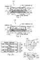
- Figure 1 is a cross-sectional view of an integrated circuit device package accordingto one embodiment of the present invention;
- Figure 2 is a cross-sectional view of an integrated circuit device package accordingto another embodiment of the present invention;
- Figure 2A is a diagrammatic illustration of detail A in Figure 2;
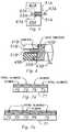
- Figure 3 is a fragmentary plan view of a coated heat spreader according to thepresent invention;
- Figure 3A is a fragmentary sectional view taken along
line 3A-3A in Figure 3, andshowing the semiconductor die and molding compound in place on the heat spreader; - Figure 4 is a fragmentary side view of an integrated circuit device packageaccording to another embodiment of the present invention;
- Figure 4A is a diagrammatic illustration of detail A in Figure 4;
- Figure 4B is a diagrammatic illustration of detail B in Figure 4;
- Figure 4C is a diagrammatic illustration of detail C in Figure 4;
- Figure 5 is a fragmentary side view of another integrated circuit device packageaccording to the invention;
- Figure 6 is a view similar to Figure 5, but depicting another integrated circuitdevice package according to the invention; and
- Figures 7A and 7B illustrate a metal component of a molded package coated witha combination of selectively applied coating materials.
- Figure 1 illustrates an electrical circuit assembly according to one embodiment ofthe present invention. In this embodiment, the electrical circuit assembly is an
integratedcircuit package 10 including an electrical circuit as embodied by integrated circuit chip 11.The integrated circuit chip 11 is mounted on achip support pad 13, and thechip supportpad 13 is mounted on a heat spreader orheat sink 15. Thepad 13 is adhered to theheatspreader 15 by anadhesive material 17. The heat spreader is preferably a metal heatspreader, for example, copper. Theadhesive material 17 is preferably a thermallyenhanced epoxy adhesive.Leads 21 are wire bonded to the chip 11, and amoldingcompound 19 is molded onto the chip 11,pad 13,heat spreader 15, leads 21 andwirebonds 22. The molding compound is typically a plastic material, for example, epoxyNovolac. Theleads 21 are partially encapsulated by themolding compound 19 andproject externally therefrom, thereby providing external electrical access to the chip 11. - Because of thermal mismatch between the
heat spreader 15 and themoldingcompound 19, undesirable delamination between theheat spreader 15 and themoldingcompound 19 can occur, resulting in the package cracking problems described above. Thepresent invention attempts to eliminate this problem by providing theheat spreader 15with a relativelythin film coating 23 applied by a thermal spray coating process, forexample, a coating of nickel aluminide applied by a flame plasma deposition process andhaving a thickness in the range of about 25 to 125 µm (0.001 to 0.005 inches) and having an adhesionstrength of approximately 7MN/m2 (1000 psi), measured in shear. Thecoating 23 significantlyenhances the adhesion between themolding compound 19 and theheat spreader 15,thereby reducing the likelihood of delamination therebetween. This technique can enhancethe adhesion by ten-fold or more, depending on factors such as the intrinsic adhesioncapability of the heat spreader surface to which thecoating 23 is applied. - Because of the very good adhesion obtained, thermal transport is enhanced byelimination of gaps or voids between the
molding compound 19 and theheat spreader 15. Thecoating 23 provides adhesion strength of about 7MN/m2 (1000 psi) or more at the interfacebetween theheat spreader 15 and thecoating 23, at the interface between thecoating 23and themolding compound 19, and within thecoating 23 itself. These interfacial adhesionstrengths can be retained over the temperature range required for assembling theintegrated circuit package 10 into a system, for example by reflow soldering, and over therequired operational temperature range of thepackage 10. These strengths are retainedthrough reflow soldering even when moisture is present in themolding compound 19.This greatly reduces the incidence of delamination and package cracking. - The
film coating 23 should be thin enough to avoid cohesive failure in the coatingitself, and should also be thin enough to avoid substantial sacrifices in thermalconductivity. The above-described example ofcoating 23 meets these requirements. - The flame plasma deposition process, also known as plasma arc deposition andplasma spray, is a well known thermal spray coating process, and a coating having thecharacteristics of the above-described
exemplary coating 23 can be readily obtained usingthis process. In the flame plasma deposition process, a plasma-forming gas (e.g. argon ornitrogen) is used both as a heat source and a propelling agent for the coating material.The gas is ionized by a high-voltage arc struck between an anode and a cathode of a spraygun and is then forced through a nozzle. As the gas leaves the nozzle, it reverts to itsnatural state and liberates a large amount of heat. The coating material, such as nickelaluminide, is provided in powdered form and is injected into the hot gas stream where it ismelted and projected at high velocity onto theheat spreader 15. The resultantnickelaluminide coating 23 is dense and strongly bonded to theheat spreader 15. Nickelaluminide is often referred to as a bond coat material because it will actually make ametallurgical weld to the surface of theheat spreader 15 during the flame plasmadeposition process, and no pre-treating of the heat spreader is necessary. - Although flame plasma deposition is the preferred method of applying the coatingmaterial, other known thermal spray processes can be used to apply the coating material.
- Referring again to Figure 1, the
leads 21 are electrically isolated from theheatspreader 15 by themolding compound 19. Therefore, thecoating 23 may be electrically conductive. The above-described nickel aluminide coating iselectrically conductive. - The embodiment of Figure 2 is generally similar to the Figure 1 embodiment (andthe same reference numerals have been used in Figure 2 to designate analogous parts)except that the chip 11 and the
leads 21 are attached directly to theheat spreader 15. Thechip 11 is attached to theheat spreader 15 using theaforementioned adhesive 17. Theleads 21 are attached to heatspreader 15 usingadhesive 18. In this embodiment, anadditional electrically insulativecoating could be provided to prevent theleads 21 from being shortedtogether by themetal heat spreader 15. Thus, in the Figure 2 embodiment, thecoating 23A could include, for example, any of a variety of well known insulating oxide materials. Onespecific example of an acceptable insulating oxide coating material is alumina. In order toobtain the desired adhesion between theheat spreader 15 and the alumina coating,however, it may be necessary to pre-treat theheat spreader 15 before depositing thealumina. One pre-treatment possibility is to mechanically abrade the heat spreader surfaceand then use flame plasma deposition to apply the desired coating of alumina onto theabraded heat spreader surface. Pre-treatment of a substrate by mechanical abrasion is awell known procedure in flame plasma deposition technology.In this embodimenttheheat spreader 15 is provided with a precoat layer of flame plasmadeposited nickel aluminide. Thereafter, an overcoat layer of flame plasma depositedalumina can be applied to the precoated heat spreader to obtain the desired insulativecoating. Thecoating 23A therefore includes a precoat of nickel aluminideand may include an overcoat layer of alumina. - As an alternative in the Figure 2 embodiment, adhesive 18 can be an electricallyinsulating tape with adhesive on both sides. The insulating tape would prevent the
leads 21 from shorting together, and theheat spreader 15 could be coated with an electricallyconductive material if desired. - As mentioned above, the
coatings coatings - Referring to Figure 2A, the
leads 21 may also be coated with a flame plasmadepositedfilm 23B to enhance adhesion of theleads 21 to themolding compound 19 andto the adhesive 18. The flame plasma depositedfilm 23A on theheat spreader 15 alsoenhances the adhesion betweenheat spreader 15 andadhesives - Figures 3 and 3A illustrate the use of the present invention with the heat spreaderof a conventional TO-220 power transistor package. The
heat spreader 25, copper in thisembodiment, is provided with a flame plasma depositedalumina coating 29 which hasbeen selectively positioned on theupper surface 26 of theheat spreader 25 by line of sightmasking outside of the die attacharea 27. Thecoating 29 can have the same thicknessand adhesion strength as disclosed above with respect to thecoating 23 of Figure 1. Theplacement of the semiconductor die 31 and molding compound 33 is shown in Figure 3A.In this embodiment, the molding compound 33 contacts only a limited portion of theuppersurface 26 of theheat spreader 25, and thecoating 29 is therefore limited to that particularportion of theupper surface 26. Thecoating 29 includes aprecoat layer of nickel aluminide and an overcoat layer of alumina. - On the other hand, the
molding compound 19 in Figures 1 and 2 contacts all of theheat spreader 15 except the bottom surface and the chip attach area. Thecoatings upper surface 39. In fact, theheatspreader 15 can be entirely encapsulated by themolding compound 19, as shown inbroken lines in Figure 1. In this case, even the bottom surface of theheat spreader 15would be coated to promote adhesion of themolding compound 19. - Referring again to the arrangement illustrated in Figures 3 and 3A, scanningacoustical microscopy has been used to compare this structure to the conventionalarrangement, which has no
coating 29. The comparison was made both before and aftertemperature cycling, and the adhesion provided by the structure of Figures 3 and 3A wasmuch improved over the conventional arrangement, even though thealumina coating 29was not optimized and theheat spreader 25 was not precoated with a bond coat material. - The molding compound 33 of Figure 3A can be molded onto the
heat spreader 25so that molding compound 33 coversheat spreader 25 in generally the same manner thatmolding compound 19 coversheat spreader 15 in Figures 1 and 2. The coverage ofcoating 29 in Figures 3 and 3A would be extended in correspondence to the extendedcoverage of the molding compound 33. - The
coating 29 of Figures 3 and 3A may also be extended to cover the entireuppersurface 26 ofheat spreader 25, including the die attacharea 27. This would provideisolation for the semiconductor die 31 and enhance the adhesion between the die attachadhesive (preferably a thermally enhanced epoxy adhesive) and thecoated heat spreader 25. Such enhanced adhesion can reduce the amount of die attach adhesive needed,resulting in improved heat transfer from the die 31 to theheat spreader 25. - Referring to Figures 1 and 2, by coating the entire
upper surface 39 of theheatspreader 15, the aforementioned advantages associated with coating the die attach areacan be realized in the embodiments of Figures 1 and 2 also. - Another embodiment of the present invention is illustrated in Figures 4, 4A, 4Band 4C. Figure 4 illustrates a semiconductor packaged
device 41 including apackageassembly 43 in which a semiconductor die orchip 59 is housed. Thepackage assembly 43includes a generallyannular package ring 45 formed from a molding compound such asepoxy Novolac. Opposite axial ends of thepackage ring 45 are closed by metal (copper inthe disclosed example) lids 47 and 49 which also function as heat spreaders. Referring toFigures 4A and 4C, the outer peripheral portions of thelids package ring 45 by layers ofadhesive material 51. Flame plasma depositedfilm coatings lids adhesive layers 51 to thelids lids package ring 45 is also enhanced. - Referring to Figure 4B, a metal (in this embodiment aluminum) die
pad 57 isprovided to support the chip or die 59 within thepackage assembly 43. Using layers of athermally enhanced epoxyadhesive material 52, thedie pad 57 is adhered on one sidethereof to the lid 47 (or alternatively the lid 49), and on the opposite side thereof to thedie 59. A flame plasma depositedfilm coating 61 covers both of the aforementioned sides of thedie pad 57 to enhance the adhesion of theadhesive layers 52 to thedie pad 57. Thus,the adhesion of thedie 59 and thelid 47 to thedie pad 57 is enhanced. In addition, theadhesion between thedie pad 57 and thelid 47 is further enhanced by the flame plasmadepositedfilm coating 53 on thelid 47, whichcoating 53 enhances the adhesion of theadhesive material 52 to thelid 47. - The
package ring 45 and thelids package ring 45 and between thelids packagering 45 and the adheredlid 49 can be considered to define a die carrier body having anoutwardly opening cavity 67 which is closed by thelid 47. As indicated above, thedie 59may be mounted on either of thelids package ring 45 is molded onto leadssuch aslead 63. Thelead 63 has an inner end which is disposed within the cavity 67 andwire bonded at 65 to thedie 59. Thelead 63 extends outwardly through thepackage ring 45 to provide external electrical access to the die. - In the embodiment of Figure 4, the flame plasma deposited
coatings coating 23 of Figure 1. Becausethe coatings of Figures 4A-4C are provided to enhance the adhesion of the adhesives tothedie pad 57 and to thelids die pad 57 and thecoating 61, at the interfaces between thecoatings lids - Figure 5 illustrates an alternative to the Figure 4 embodiment. Figure 5 isgenerally similar to Figure 4 but differs therefrom because it does not include a moldedpackage ring as in Figure 4. A metal base or die carrier body 49A defines an outwardlyopening cavity 67A which is closed by a metal lid or
cap 47A. The base 49A and thecap 47A may be, for example, aluminum. The opposed outer peripheral portions of thecap 47A and the base 49A are adhered to one another byadhesive material 51A. Thelead 63A is captured between thecap 47A and the base 49A, and is adhesively secured in placeby theadhesive material 51A. The flame plasma depositedfilm coatings cap 47A and the base 49A to enhance the adhesion of theadhesive material 51A to thecap 47A and thebase 49A. Similarly to the Figure 4 embodiment, a semiconductor die is disposed withinthe closed cavity 67A, and may be mounted on either the base 49A or thecap 47A. - Figure 6 illustrates another alternative to the Figure 4 embodiment. Figure 6 isgenerally similar to Figure 4 but differs therefrom because the molded
package ring 45B ismolded onto theheat spreader 49B as well as theleads 63B. The leads 63B are attachedto the surface ofheat spreader 49B by adhesive 51B, and thereafter thepackage ring 45Bis molded onto theheat spreader 49B and theleads 63B. The surface ofheat spreader 49B is provided with a flame plasma deposited coating 55B to enhance the adhesionbetweenheat spreader 49B andpackage ring 45B. The adhesion between adhesive 51Bandheat spreader 49B is also enhanced by the flame plasma deposited coating on the heatspreader. As in Figure 2, the coating onheat spreader 49B may include an electrically insulative layer(such as alumina) to prevent theleads 63B from being shorted together by themetal heatspreader 49B, or the adhesive 51B can be an insulating tape with adhesive on both sides. - After the
package ring 45B has been molded onto theheat spreader 49B and leads63B, thelid 47B is attached to thepackage ring 45B using adhesive 51B. - Referring now to Figures 1, 4, 5 and 6, the leads illustrated therein may also becoated with flame plasma deposited material as discussed above with respect to Figures 2and 2A. Such lead coating enhances the adhesion between: the
leads 21 andmoldingcompound 19 of Figure 1; theleads 63 and the moldedpackage ring 45 of Figure 4; theleads 63A andadhesive material 51A of Figure 5; theleads 63B and moldedpackage ring 45B of Figure 6; and theleads 63B and adhesive 51B of Figure 6. As is clear from thedrawings, the flame plasma deposited coating need only be applied to those portions of theleads which contact the molding compound and/or the adhesive. Such selective coating isreadily achieved using conventional masking techniques. - Coatings such as the exemplary coatings described herein can be used together inselective combination, depending on the requirements of the particular package. As anexample, referencing Figure 7A, nickel aluminide can be applied only on selected
areas 73of a surface of ametal component 71 such as a heat spreader, and alumina can be appliedto the remainingareas 75 which are not already coated with nickel aluminide. This provides minimal deposition thickness and improved thermal conductivity in theelectricallyinsulative areas 75. As another example, referencing Figure 7B, the aluminacan be applied over the entire surface of themetal component 71, including the nickelaluminide-coatedareas 73 and theareas 75. Theareas 75 have greater dielectric strengththan theareas 73 while having a deposition thickness approximately equal to thedeposition thickness of theareas 73. - Although exemplary embodiments of the invention are described above in detail,this description is not to be construed as limiting because the invention can be practiced ina variety of embodiments.
Claims (18)
- An electrical circuit assembly, comprising anelectrical circuit (11, 31); a metal heat spreader (15,25, 49B) disposed in thermal contact with saidelectrical circuit for carrying heat away from saidelectrical circuit; and a molded structure (19, 33, 45B)molded onto said heat spreader; characterised inthat said heat spreader has a coating (23, 23A, 29, 53, 53A, 55, 55A, 55B, 61)of nickel aluminide provided thereon for enhancing theadhesion capability thereof.
- An electrical circuit assembly according to anypreceding claim, wherein said coating (23, 23A, 29, 53, 53A, 55, 55A, 55B, 61)has a thickness in a range of approximately 25 to 125 µm(0.001 to 0.005 inches).
- An electrical circuit assembly according to anypreceding claim, wherein said coating (23, 23A, 29, 53, 53A, 55, 55A, 55B, 61)has an adhesion strength of approximately 7MN/m2(1000 psi).
- An electrical circuit assembly according to anypreceding claim, wherein said electrical circuit is asemiconductor integrated circuit chip.
- An electrical circuit assembly according to claim4, wherein a chip support pad (13) is mounted on saidheat spreader (15), said chip (11) is mounted on saidchip support pad, said structure is a molded casing (19)molded onto said chip support pad (13), and said moldedcasing (19) is constructed from a plastic moldingcompound.
- An electrical circuit assembly according toclaim 4, wherein said chip (11, 31) is mounted directlyon said heat spreader (15, 25).
- An electrical circuit according to any precedingclaim, including a plurality of leads (21, 63B) connectedto said electrical circuit, said leads having a coating(23B) of deposited material provided thereon forenhancing the adhesion capability thereof, said coated leads being adhesively (18, 51B) attached to said coatedheat spreader (15, 49B), said molded structure(19, 45B) being molded onto said coated leads (21, 63B),said leads projecting exteriorly of said molded casing toprovide external electrical access to said electricalcircuit (11), and said heat spreader is provided with anelectrically insulative coating on the said coatingof nickel aluminide such that said leads are electricallyisolated from one another.
- An electrical circuit assembly according to anypreceding claim, wherein the nickel aluminide coating isflame plasma deposited material.
- An electrical circuit assembly according to anyone of claims 1 to 7, wherein the nickel aluminidecoating is thermal spray deposited.
- An electrical circuit assembly comprising: anelectrical circuit (59); a package assembly (43) forhousing said electrical circuit therein; support means(49A, 49B, 57) coacting with said package assembly (43)for supporting said electrical circuit (59) in saidpackage assembly (43); and at least one of said packageassembly and said support means including at least onemetal element (47, 47A, 49, 49A, 49B, 57); characterisedin that a coating of deposited nickel aluminide (53, 53A,55, 55A, 55B, 61) is provided on the or at least one saidmetal element (47, 47A, 49, 49A, 49B, 57) for enhancing theadhesion capability thereof, and said coated metalelement (47, 47A, 49, 49A, 49B 57) has a layer of adhesivematerial (51, 51A, 51B, 52) applied over said coating.
- An electrical circuit assembly according toclaim 10, wherein said package assembly (43) includes ametal lid (47, 47A, 47B) constituting said coated metalelement and having thereon a respective coating of nickelaluminide (53, 53A) and a respective layer ofadhesive material (51, 51A, 51B 52) applied over saidcoating.
- An electrical circuit assembly to claim 11,wherein said package assembly (43) includes: a diecarrier body (49), and a generally annular, moldedpackage ring portion (45), said package ring portion (45)having opposite axial ends, one of said axial ends beingclosed by said die carrier body (49), said layer ofadhesive material (52) adhering said metal lid (47) tosaid package ring portion (45), said metal lid (47) beingco-operable with said die carrier body (49) to define anenclosed cavity within said package ring (45), and saidelectrical circuit (59) is disposed within said cavity.
- An electrical circuit assembly according to oneof claims 11 or 12 wherein said electrical circuit is asemiconductor die (59), said support means (49A, 49B, 57)includes a metal die pad (57) constituting a furthermetal element, said metal die pad (57) having arespective coating of nickel aluminide (61) and arespective layer of adhesive material (52) applied oversaid coating of nickel aluminide (61), said respectivelayers of adhesive material (52) adhering saidsemiconductor die (59) to said metal die pad (57) andsaid metal die pad (57) to said metal lid (47).
- An electrical circuit assembly according to anyone of claims 10 to 13, wherein the or a said coatedmetal element is a heat spreader (47, 49, 49B).
- A method of manufacturing a semiconductorpackaged device, comprising the steps of: providing ametal heat spreader (15, 25, 49B) for carrying heat outof said semiconductor packaged device; and providingmolding compound (19, 33, 45B) to be adhered to the heatspreader; characterised by enhancing the adhesioncapability of the heat spreader by using deposition toapply a coating (23, 23A, 53, 55B) of nickel aluminide toa surface of the heat spreader; and thereafter, applyingthe moulding compound to the coated surface of the heatspreader.
- A method according to claim 15, including thestep of mechanically abrading said surface beforeapplying said coating thereto.
- The method according to claim 15 or claim 16,comprising using flame plasma deposition.
- A method according to claim 15 or claim 16,comprising using a thermal spray deposition.
Applications Claiming Priority (2)
| Application Number | Priority Date | Filing Date | Title |
|---|---|---|---|
| US931797 | 1992-08-18 | ||
| US07/931,797US5362680A (en) | 1992-08-18 | 1992-08-18 | Technique for enhancing adhesion capability of heat spreaders in molded packages |
Publications (2)
| Publication Number | Publication Date |
|---|---|
| EP0588501A1 EP0588501A1 (en) | 1994-03-23 |
| EP0588501B1true EP0588501B1 (en) | 2000-07-26 |
Family
ID=25461360
Family Applications (1)
| Application Number | Title | Priority Date | Filing Date |
|---|---|---|---|
| EP93306511AExpired - LifetimeEP0588501B1 (en) | 1992-08-18 | 1993-08-18 | Technique for enhancing adhesion capability of heat spreaders in molded packages |
Country Status (5)
| Country | Link |
|---|---|
| US (2) | US5362680A (en) |
| EP (1) | EP0588501B1 (en) |
| JP (1) | JPH0714858A (en) |
| DE (1) | DE69329090T2 (en) |
| TW (1) | TW248614B (en) |
Families Citing this family (33)
| Publication number | Priority date | Publication date | Assignee | Title |
|---|---|---|---|---|
| US6096756A (en)* | 1992-09-21 | 2000-08-01 | Albert Einstein College Of Medicine Of Yeshiva University | Method of simultaneously enhancing analgesic potency and attenuating dependence liability caused by morphine and other bimodally-acting opioid agonists |
| KR960000706B1 (en)* | 1993-07-12 | 1996-01-11 | 한국전기통신공사 | Plastic package structure for power device and manufacturing method |
| US5536906A (en)* | 1993-07-23 | 1996-07-16 | Texas Instruments Incorporated | Package for integrated circuits |
| US5434105A (en)* | 1994-03-04 | 1995-07-18 | National Semiconductor Corporation | Process for attaching a lead frame to a heat sink using a glob-top encapsulation |
| JP2635933B2 (en)* | 1994-07-05 | 1997-07-30 | インターナショナル・ビジネス・マシーンズ・コーポレイション | Method for manufacturing semiconductor device |
| JPH0846098A (en)* | 1994-07-22 | 1996-02-16 | Internatl Business Mach Corp <Ibm> | Equipment and method for forming direct heat conduction path |
| US5581443A (en)* | 1994-09-14 | 1996-12-03 | Kabushiki Kaisha Toshiba | Structure for cooling a circuit module having a circuit board and a heat-generating IC chip mounted on the board, and portable electronic apparatus incorporating the structure |
| US5784256A (en)* | 1994-09-14 | 1998-07-21 | Kabushiki Kaisha Toshiba | Portable computer having a circuit board including a heat-generating IC chip and a metal frame supporting the circuit board |
| US5573845A (en)* | 1994-12-09 | 1996-11-12 | Olin Corporation | Superficial coating layer having acicular structures for electrical conductors |
| US5972736A (en)* | 1994-12-21 | 1999-10-26 | Sun Microsystems, Inc. | Integrated circuit package and method |
| JP2795626B2 (en)* | 1995-08-21 | 1998-09-10 | 北川工業株式会社 | Electronic components with heat dissipation function |
| US5886400A (en)* | 1995-08-31 | 1999-03-23 | Motorola, Inc. | Semiconductor device having an insulating layer and method for making |
| US6030857A (en) | 1996-03-11 | 2000-02-29 | Micron Technology, Inc. | Method for application of spray adhesive to a leadframe for chip bonding |
| US5874776A (en)* | 1997-04-21 | 1999-02-23 | International Business Machines Corporation | Thermal stress relieving substrate |
| US5940687A (en)* | 1997-06-06 | 1999-08-17 | International Business Machines Corporation | Wire mesh insert for thermal adhesives |
| US5956226A (en)* | 1997-10-01 | 1999-09-21 | Motorola, Inc. | Electrochemical capacitor used for thermal management |
| US6529379B1 (en) | 1998-10-13 | 2003-03-04 | International Business Machines Corporation | Article exhibiting enhanced adhesion between a dielectric substrate and heat spreader and method |
| US6753922B1 (en)* | 1998-10-13 | 2004-06-22 | Intel Corporation | Image sensor mounted by mass reflow |
| US6084775A (en)* | 1998-12-09 | 2000-07-04 | International Business Machines Corporation | Heatsink and package structures with fusible release layer |
| US6893523B2 (en) | 1999-02-11 | 2005-05-17 | International Business Machines Corporation | Method for bonding heat sinks to overmold material |
| US6370767B1 (en) | 1999-10-04 | 2002-04-16 | Artesyn Technologies, Inc. | Method for fabricating an electrical apparatus |
| US6836205B2 (en)* | 2000-10-04 | 2004-12-28 | Honeywell International, Inc. | Thermal switch containing resistance temperature detector |
| DE20019053U1 (en)* | 2000-11-09 | 2001-02-08 | Robert Bosch Gmbh, 70469 Stuttgart | Heatsink traces arrangement |
| US6751099B2 (en)* | 2001-12-20 | 2004-06-15 | Intel Corporation | Coated heat spreaders |
| US20050136640A1 (en)* | 2002-01-07 | 2005-06-23 | Chuan Hu | Die exhibiting an effective coefficient of thermal expansion equivalent to a substrate mounted thereon, and processes of making same |
| US6841413B2 (en)* | 2002-01-07 | 2005-01-11 | Intel Corporation | Thinned die integrated circuit package |
| KR100902766B1 (en)* | 2002-09-27 | 2009-06-15 | 페어차일드코리아반도체 주식회사 | Discrete Packages with Insulated Ceramic Heat Sink |
| US20040125563A1 (en)* | 2002-12-31 | 2004-07-01 | Vrtis Joan K. | Coating for a heat dissipation device and a method of fabrication |
| US7005728B1 (en) | 2004-06-03 | 2006-02-28 | National Semiconductor Corporation | Lead configuration for inline packages |
| JP4748173B2 (en)* | 2008-03-04 | 2011-08-17 | 株式会社デンソー | Semiconductor module and manufacturing method thereof |
| US9070662B2 (en) | 2009-03-05 | 2015-06-30 | Volterra Semiconductor Corporation | Chip-scale packaging with protective heat spreader |
| KR102031731B1 (en) | 2012-12-18 | 2019-10-14 | 삼성전자주식회사 | Semiconductor package and method of manufacturing the same |
| FR3043679B1 (en)* | 2015-11-12 | 2021-07-23 | Aptar Stelmi Sas | PROCESS FOR TREATING AN ELASTOMERIC PACKAGING ELEMENT, AND PACKAGING ELEMENT THUS TREATED. |
Family Cites Families (17)
| Publication number | Priority date | Publication date | Assignee | Title |
|---|---|---|---|---|
| US3821039A (en)* | 1973-03-22 | 1974-06-28 | Rca Corp | Method of epitaxially depositing a semiconductor material on a substrate |
| JPS55132048A (en)* | 1979-04-03 | 1980-10-14 | Toshiba Corp | Semiconductor device |
| DE3379928D1 (en)* | 1982-12-22 | 1989-06-29 | Sumitomo Electric Industries | Substrate for mounting semiconductor element |
| JPS60110146A (en)* | 1983-11-18 | 1985-06-15 | Matsushita Electronics Corp | Resin-sealed type semiconductor device |
| JPS60137041A (en)* | 1983-12-26 | 1985-07-20 | Matsushita Electronics Corp | Resin-sealed semiconductor device |
| JPS61343A (en)* | 1984-06-13 | 1986-01-06 | 小河 政之 | Heating and cooling treating disc |
| JPS613438A (en)* | 1984-06-15 | 1986-01-09 | Sumitomo Electric Ind Ltd | Plastic-sealed ic |
| JPS61137351A (en)* | 1984-12-07 | 1986-06-25 | Matsushita Electronics Corp | Heat sink plate for package |
| US4943844A (en)* | 1985-11-22 | 1990-07-24 | Texas Instruments Incorporated | High-density package |
| US4874722A (en)* | 1987-04-16 | 1989-10-17 | Texas Instruments Incorporated | Process of packaging a semiconductor device with reduced stress forces |
| US5050040A (en)* | 1988-10-21 | 1991-09-17 | Texas Instruments Incorporated | Composite material, a heat-dissipating member using the material in a circuit system, the circuit system |
| US5073521A (en)* | 1989-11-15 | 1991-12-17 | Olin Corporation | Method for housing a tape-bonded electronic device and the package employed |
| US5053357A (en)* | 1989-12-27 | 1991-10-01 | Motorola, Inc. | Method of aligning and mounting an electronic device on a printed circuit board using a flexible substrate having fixed lead arrays thereon |
| JPH03270057A (en)* | 1990-03-19 | 1991-12-02 | Nec Corp | Integrated circuit device |
| SG52332A1 (en)* | 1990-09-24 | 1998-09-28 | Texas Instruments Inc | Insulated lead frame for integrated circuits and method of manufacture thereof |
| US5138114A (en)* | 1990-09-27 | 1992-08-11 | Texas Instruments Incorporated | Hybrid/microwave enclosures and method of making same |
| US5087962A (en)* | 1991-02-25 | 1992-02-11 | Motorola Inc. | Insulated lead frame using plasma sprayed dielectric |
- 1992
- 1992-08-18USUS07/931,797patent/US5362680A/ennot_activeExpired - Lifetime
- 1993
- 1993-08-17JPJP5203191Apatent/JPH0714858A/enactivePending
- 1993-08-18DEDE69329090Tpatent/DE69329090T2/ennot_activeExpired - Fee Related
- 1993-08-18EPEP93306511Apatent/EP0588501B1/ennot_activeExpired - Lifetime
- 1994
- 1994-02-22TWTW083101474Apatent/TW248614B/zhnot_activeIP Right Cessation
- 1994-07-06USUS08/271,334patent/US5422788A/ennot_activeExpired - Lifetime
Also Published As
| Publication number | Publication date |
|---|---|
| DE69329090D1 (en) | 2000-08-31 |
| US5362680A (en) | 1994-11-08 |
| US5422788A (en) | 1995-06-06 |
| DE69329090T2 (en) | 2001-03-22 |
| EP0588501A1 (en) | 1994-03-23 |
| JPH0714858A (en) | 1995-01-17 |
| TW248614B (en) | 1995-06-01 |
Similar Documents
| Publication | Publication Date | Title |
|---|---|---|
| EP0588501B1 (en) | Technique for enhancing adhesion capability of heat spreaders in molded packages | |
| US6093960A (en) | Semiconductor package having a heat spreader capable of preventing being soldered and enhancing adhesion and electrical performance | |
| KR100241476B1 (en) | Insulated leadframes for integrated circuits and manufacturing method thereof | |
| KR100251677B1 (en) | Bump Formation Method and Formation Method of Bump | |
| US6201301B1 (en) | Low cost thermally enhanced flip chip BGA | |
| US6177725B1 (en) | Semiconductor device having an improved structure for preventing cracks, improved small-sized semiconductor and method of manufacturing the same | |
| US7256431B2 (en) | Insulating substrate and semiconductor device having a thermally sprayed circuit pattern | |
| EP1188182B1 (en) | A method of assembling a semiconductor device package | |
| JP3068534B2 (en) | Semiconductor device | |
| US20010024840A1 (en) | Adhesion enhanced semiconductor die for mold compound packaging | |
| JPS59123248A (en) | Semiconductor vessel | |
| KR19990037421A (en) | Molded BGA Type Semiconductor Device and Manufacturing Method Thereof | |
| JPH11514149A (en) | Electronic package with improved thermal properties | |
| US5814882A (en) | Seal structure for tape carrier package | |
| US5434449A (en) | Semiconductor device in a single package with high wiring density and a heat sink | |
| TW387134B (en) | Method of manufacturing a | |
| WO1996007204A1 (en) | Ultra-thin composite package for integrated circuits | |
| US5539253A (en) | Resin-sealed semiconductor device | |
| US5672915A (en) | Ceramic coated plastic package | |
| US5087962A (en) | Insulated lead frame using plasma sprayed dielectric | |
| JPH0491458A (en) | Semiconductor device | |
| JP2934421B2 (en) | Resin encapsulated semiconductor device with heat sink | |
| US6541870B1 (en) | Semiconductor package with stacked chips | |
| US4974052A (en) | Plastic packaged semiconductor device | |
| US20250079259A1 (en) | Package for integrated circuit with heat dissipation |
Legal Events
| Date | Code | Title | Description |
|---|---|---|---|
| PUAI | Public reference made under article 153(3) epc to a published international application that has entered the european phase | Free format text:ORIGINAL CODE: 0009012 | |
| AK | Designated contracting states | Kind code of ref document:A1 Designated state(s):DE FR GB IT NL | |
| 17P | Request for examination filed | Effective date:19940922 | |
| 17Q | First examination report despatched | Effective date:19960112 | |
| GRAG | Despatch of communication of intention to grant | Free format text:ORIGINAL CODE: EPIDOS AGRA | |
| GRAG | Despatch of communication of intention to grant | Free format text:ORIGINAL CODE: EPIDOS AGRA | |
| GRAH | Despatch of communication of intention to grant a patent | Free format text:ORIGINAL CODE: EPIDOS IGRA | |
| GRAH | Despatch of communication of intention to grant a patent | Free format text:ORIGINAL CODE: EPIDOS IGRA | |
| GRAA | (expected) grant | Free format text:ORIGINAL CODE: 0009210 | |
| AK | Designated contracting states | Kind code of ref document:B1 Designated state(s):DE FR GB IT NL | |
| PG25 | Lapsed in a contracting state [announced via postgrant information from national office to epo] | Ref country code:NL Free format text:LAPSE BECAUSE OF FAILURE TO SUBMIT A TRANSLATION OF THE DESCRIPTION OR TO PAY THE FEE WITHIN THE PRESCRIBED TIME-LIMIT Effective date:20000726 Ref country code:IT Free format text:LAPSE BECAUSE OF FAILURE TO SUBMIT A TRANSLATION OF THE DESCRIPTION OR TO PAY THE FEE WITHIN THE PRE;WARNING: LAPSES OF ITALIAN PATENTS WITH EFFECTIVE DATE BEFORE 2007 MAY HAVE OCCURRED AT ANY TIME BEFORE 2007. THE CORRECT EFFECTIVE DATE MAY BE DIFFERENT FROM THE ONE RECORDED.SCRIBED TIME-LIMIT Effective date:20000726 Ref country code:FR Free format text:LAPSE BECAUSE OF FAILURE TO SUBMIT A TRANSLATION OF THE DESCRIPTION OR TO PAY THE FEE WITHIN THE PRESCRIBED TIME-LIMIT Effective date:20000726 | |
| REF | Corresponds to: | Ref document number:69329090 Country of ref document:DE Date of ref document:20000831 | |
| EN | Fr: translation not filed | ||
| NLV1 | Nl: lapsed or annulled due to failure to fulfill the requirements of art. 29p and 29m of the patents act | ||
| PLBE | No opposition filed within time limit | Free format text:ORIGINAL CODE: 0009261 | |
| STAA | Information on the status of an ep patent application or granted ep patent | Free format text:STATUS: NO OPPOSITION FILED WITHIN TIME LIMIT | |
| 26N | No opposition filed | ||
| REG | Reference to a national code | Ref country code:GB Ref legal event code:IF02 | |
| PGFP | Annual fee paid to national office [announced via postgrant information from national office to epo] | Ref country code:DE Payment date:20080829 Year of fee payment:16 | |
| PGFP | Annual fee paid to national office [announced via postgrant information from national office to epo] | Ref country code:GB Payment date:20080708 Year of fee payment:16 | |
| GBPC | Gb: european patent ceased through non-payment of renewal fee | Effective date:20090818 | |
| PG25 | Lapsed in a contracting state [announced via postgrant information from national office to epo] | Ref country code:DE Free format text:LAPSE BECAUSE OF NON-PAYMENT OF DUE FEES Effective date:20100302 | |
| PG25 | Lapsed in a contracting state [announced via postgrant information from national office to epo] | Ref country code:GB Free format text:LAPSE BECAUSE OF NON-PAYMENT OF DUE FEES Effective date:20090818 |