EP0587254B1 - Reusable stackable tray for cans - Google Patents
Reusable stackable tray for cansDownload PDFInfo
- Publication number
- EP0587254B1 EP0587254B1EP19930202786EP93202786AEP0587254B1EP 0587254 B1EP0587254 B1EP 0587254B1EP 19930202786EP19930202786EP 19930202786EP 93202786 AEP93202786 AEP 93202786AEP 0587254 B1EP0587254 B1EP 0587254B1
- Authority
- EP
- European Patent Office
- Prior art keywords
- tray
- cans
- floor
- members
- loaded
- Prior art date
- Legal status (The legal status is an assumption and is not a legal conclusion. Google has not performed a legal analysis and makes no representation as to the accuracy of the status listed.)
- Expired - Lifetime
Links
Images


Classifications
- B—PERFORMING OPERATIONS; TRANSPORTING
- B65—CONVEYING; PACKING; STORING; HANDLING THIN OR FILAMENTARY MATERIAL
- B65D—CONTAINERS FOR STORAGE OR TRANSPORT OF ARTICLES OR MATERIALS, e.g. BAGS, BARRELS, BOTTLES, BOXES, CANS, CARTONS, CRATES, DRUMS, JARS, TANKS, HOPPERS, FORWARDING CONTAINERS; ACCESSORIES, CLOSURES, OR FITTINGS THEREFOR; PACKAGING ELEMENTS; PACKAGES
- B65D21/00—Nestable, stackable or joinable containers; Containers of variable capacity
- B65D21/02—Containers specially shaped, or provided with fittings or attachments, to facilitate nesting, stacking, or joining together
- B—PERFORMING OPERATIONS; TRANSPORTING
- B65—CONVEYING; PACKING; STORING; HANDLING THIN OR FILAMENTARY MATERIAL
- B65D—CONTAINERS FOR STORAGE OR TRANSPORT OF ARTICLES OR MATERIALS, e.g. BAGS, BARRELS, BOTTLES, BOXES, CANS, CARTONS, CRATES, DRUMS, JARS, TANKS, HOPPERS, FORWARDING CONTAINERS; ACCESSORIES, CLOSURES, OR FITTINGS THEREFOR; PACKAGING ELEMENTS; PACKAGES
- B65D71/00—Bundles of articles held together by packaging elements for convenience of storage or transport, e.g. portable segregating carrier for plural receptacles such as beer cans or pop bottles; Bales of material
- B65D71/70—Trays provided with projections or recesses in order to assemble multiple articles, e.g. intermediate elements for stacking
- B—PERFORMING OPERATIONS; TRANSPORTING
- B65—CONVEYING; PACKING; STORING; HANDLING THIN OR FILAMENTARY MATERIAL
- B65D—CONTAINERS FOR STORAGE OR TRANSPORT OF ARTICLES OR MATERIALS, e.g. BAGS, BARRELS, BOTTLES, BOXES, CANS, CARTONS, CRATES, DRUMS, JARS, TANKS, HOPPERS, FORWARDING CONTAINERS; ACCESSORIES, CLOSURES, OR FITTINGS THEREFOR; PACKAGING ELEMENTS; PACKAGES
- B65D2501/00—Containers having bodies formed in one piece
- B65D2501/24—Boxes or like containers with moulded compartments or partitions
- B65D2501/24006—Details relating to bottle crates
- B65D2501/2405—Construction
- B65D2501/24063—Construction of the walls
- B65D2501/24089—Height of the side walls
- B65D2501/24108—Height of the side walls corresponding to part of the height of the bottles
- Y—GENERAL TAGGING OF NEW TECHNOLOGICAL DEVELOPMENTS; GENERAL TAGGING OF CROSS-SECTIONAL TECHNOLOGIES SPANNING OVER SEVERAL SECTIONS OF THE IPC; TECHNICAL SUBJECTS COVERED BY FORMER USPC CROSS-REFERENCE ART COLLECTIONS [XRACs] AND DIGESTS
- Y02—TECHNOLOGIES OR APPLICATIONS FOR MITIGATION OR ADAPTATION AGAINST CLIMATE CHANGE
- Y02W—CLIMATE CHANGE MITIGATION TECHNOLOGIES RELATED TO WASTEWATER TREATMENT OR WASTE MANAGEMENT
- Y02W30/00—Technologies for solid waste management
- Y02W30/50—Reuse, recycling or recovery technologies
- Y02W30/80—Packaging reuse or recycling, e.g. of multilayer packaging
Definitions
- the present inventionrelates to trays for transporting and storing containers such as beverage containers, and more particularly for those storing two or more six-packs of pull-top aluminium cans. It further relates to such trays which can be securely stacked one on top of another both when full and when empty.
- Pull-top aluminium cans for soft drinks, other beverages and the likeare stored and transported during the distribution stage typically in short-walled cardboard trays or in cardboard boxes.
- bottlesbecause of the ever increasing cost in disposable tertiary packaging, returnable, reusable containers are becoming popular for the storage and handling of bottles.
- pull-top aluminium cansunlike plastic or glass bottles which have rounded edges on their crown or top, pull-top aluminium cans have square sharp corners (as compared with bottle tops) where the top of the can attaches to the sides thereof. Therefore, particular difficulties have been encountered in the stacking and manipulating of the trays of cans stacked relative to one another.
- GB 1152038discloses a bottle case which displays these problems in that it comprises a base having circular indentations defined by an inclined surface, for locating the tops of bottles in a subjacent crate. These indentations serve to prevent sliding movement between stacked crates.
- Another object of the present inventionis to provide a novel, sturdy, reusable tray for storing and handling containers, and such tray having a webbed floor design which is interesting and aesthetically pleasing.
- a further object of the present inventionis to provide a sturdy reusable tray for supporting, storing and transporting beverage containers which tray is lightweight and thus can be easily manipulated and carried, and which can also be economically constructed.
- a unique stackable, reusable tray in accordance with attached claim 1is provided especially designed for stacking and storing cans having sharp top edges.
- the trayhas amongst other things, protuberance means comprising a plurality of spaced,island protuberance members.
- the protuberance membershave their bottom perimeters defining edges bevelled preferably at an angle of approximately twenty-five degrees plus or minus five degrees relative to the rest of the floor structure.
- the bottom surfaces of the protuberance membersthereby are configured so that a full tray can be easily slid and pivoted on the top of a layer of aluminium cans directly beneath it.
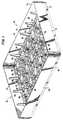
- Figure 1is a top perspective view of a reusable stackable tray for cans of the present invention.
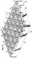
- Figure 2is is a perspective view of the tray of Figure 1 when upside down.
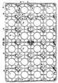
- Figure 3ais a top plan view of the tray of Figure 1.
- Figure 3bis a view similar to that of Figure 3a illustrating a variation on the design of the tray of Figure 1.
- Figure 4is is a bottom plan view of the tray of Figure 1.
- Figure 5is an end elevational view of the tray of Figure 1.
- Figure 6is a side elevational view of the tray of Figure 1.
- Figure 7is a fragmentary cross-sectional view of a side (or end) of a pair of empty trays of Figure 1 showing their interlocking nesting arrangement.
- Figure 8is a cross-sectional view of a portion of the tray of Figure 1 when loaded, locked and supported on a similar said loaded tray.
- Figure 9is a view similar to that of Figure 8 showing the trays thereof in a lock broken and sliding relation.
- Figure 10is an enlarged cross-sectional view taken along line 10-10 in Figure 3a.
- a reusable, stackable tray for cansis illustrated generally at 20, and is formed by a unitary integral plastic construction. It comprises a pair of end walls 22, 24, and a pair of opposed side walls 26, 28 wherein the end and side walls are integrally joined to form four rounded corners as shown for example at 30. As seen, the end and side walls 22, 24, 26, 28 form a rectangular structure shown generally at 32.
- a floor structure designated generally by reference numeral 34is positioned within and secured to the base of the rectangular structure 32.
- the perimeter structure 36 of the floor structure 34has its outer surfaces 37 spaced inward about the entire perimeter thereof inside of the inside surface 38 of the rectangular structure 34 to thereby provide a stepped-in design. This allows one tray 20 to be stacked and nested securely, but removably, within another similar or identical empty tray 20' and thereby resist relative lateral movement as to the surface 38' of the rectangular structure 34'. This nesting relation is best illustrated in Figure 7.
- the floor structure 34defines a web-like construction which minimizes the use of the plastic material thereby making the tray 20 lighter and easier to handle and also reducing the amount of the plastic construction material required. It further presents a pleasing and interesting design.
- the central dividing struts 42, 44 thereofextending, respectively, between the centers of the opposed side walls 26, 28 and the centers of the opposed end walls 22, 24 divide the floor structure 34 into four equal cells shown generally at 46, 48, 50 and 52, and aid in manufacturing by providing flow channels for the plastic material from the point of injection at the part center to the walls. Each cell then represents the storage space for an interconnected six-pack of beverage cans, and includes six spaced circular members such as shown by 54 in two-by-three arrays.
- redoubt memberssuch as shown by 56 are positioned in the middle of four adjacent circular members 54. Members 56 are referred to as downward projections because they project downwardly from the bottom or outer surface of floor structure 34, as explained below.
- a plurality of strutssuch as shown generally at 58 then interconnects the circular members 54, the redoubt members 56, and the floor perimeter structure 36.
- the struts 58comprise lateral struts such as shown by 60 which directly connect laterally adjacent circular members 54, longitudinal struts such as shown at 62 which directly connect longitudinally adjacent circular members 54, and radial struts such as shown at 64 which directly connect the sides of the redoubt members 56 to the circular members 54.
- radial struts 64extend therethrough, as shown in Figure 3a, for example.
- the radial struts 64do not extend through the redoubt members, as illustrated in Figure 3b.
- the dividing struts 42, 44extend through the redoubt members 56 positioned between adjacent cells 46, 48, 50 or 52.
- Partial side and end engaging redoubt memberssuch as shown at 66, 68, respectively, are positioned spaced along the floor perimeter structure 34, and are shown in elevation in Figures 5 and 6. These partial side and end engaging redoubt members 66, 68 have lateral or longitudinal redoubt struts 70, 72, respectively, extending through them as shown. Additionally, the corners such as shown at 74 of the floor perimeter structure 34 are rounded and have corner engaging redoubt members thereat such as shown at 76.
- each of the struts 58, redoubt members 56, and circular members 54all have their upper surfaces defining a smooth upper plane illustrated generally at 78 on which beverage cans can be positioned, supported and easily slid along without obstruction for inserting the cans into the tray 20 and removing them from it.
- a plurality of spaced reinforcing postssuch as shown at 79, interconnect the floor structure 34 with the rectangular structure 32 by engaging the top of adjacent lateral or longitudinal struts 60, 62 and extending up and secured to the inside surface 38 of the rectangular structure 32.
- the redoubt members 56are each formed by a continuous upright wall 80 and a redoubt floor 82 secured at the bottom end thereof, as best shown in Figure 10.
- the redoubt walls 80are configured in a square-like shape having rounded corners 83 and with the middles 84 of each of the sides thereof (where the radial struts 64 engage) being curved inwardly a slight amount.
- the bottom surfaces of the redoubt walls 81lie generally in the plane of the bottom surfaces of the struts 58, the floor perimeter structure 36 and the circular members 54.
- the redoubt floor 82extends below that plane.
- the redoubt floor 82has about its entire bottom perimeter a bevelled edge 85 which is formed at an angle 86 of, for example, twenty-five degrees plus or minus five degrees relative to the bottom plane of the rest of the floor structure 36. This angle is appropriate for the current material and market can design. However, this angle would be adjusted as needed to accommodate different materials and can designs.
- redoubt members 56assist the trays 20 when full to stack securely upon layers of cans 88 beneath them, as shown in Figure 8.
- the cans 88are those such as described earlier herein and have square sharp top corners 90. They also allow the tray 20 to be twisted or pivoted slightly while stacked on a similar layer of cans 88 therebeneath and then slid easily off of the loaded tray beneath it. This motion is best illustrated in Figure 9. This allows a delivery driver, for example, to pull off the top tray 20 of any tall stack without having to lift that top tray. In other words, a loaded tray 20 can be easily slid off the loaded tray directly beneath it.
- These redoubt members 56are also spaced evenly relative to one another to conform to a twenty-four can configuration. It is also within the scope of this invention for tray 20 to be configured and proportioned differently as needed to accommodate different numbers, sizes and arrangements of containers.
Landscapes
- Engineering & Computer Science (AREA)
- Mechanical Engineering (AREA)
- Stackable Containers (AREA)
- Containers Having Bodies Formed In One Piece (AREA)
- Catalysts (AREA)
- Table Devices Or Equipment (AREA)
- Table Equipment (AREA)
- Laminated Bodies (AREA)
- Details Of Rigid Or Semi-Rigid Containers (AREA)
Abstract
Description
Claims (6)
- A can tray (20) comprising:floor structure (34) having a floor bottom; andwall structure (32) connected to and extending up from said floor structure;
characterised byprotuberance means (56, 66, 68) for locking the tray when loaded on alayer of rimmed cans therebeneath in a locked position wherein free sliding onthe layer is blocked and for unlocking the locked and loaded tray by twisting theloaded tray a slight amount about a generally vertical axis to an unlockedposition wherein the loaded tray, with no significant lifting thereof, can be slidon the layer of rimmed cans therebeneath;
wherein said protuberance means includes a plurality of spaced, islandprotuberance members, each having a bevelled edge perimeter,secured to and depending down from said floor bottomand on which the loaded tray when in the unlocked position can slide on the rimsof the cans therebeneath. - The can tray of claim 1 wherein said protuberance members (56, 66, 68)are positioned between adjacent rimmed cans in the layer therebeneath when theloaded tray is in the locked position.
- The can tray of claim 1 or 2 wherein said floor structure includes aplurality of struts (44, 62, 64, 70, 72) connected to said protuberance members.
- The can tray of claim 3 wherein said floor structure include a plurality ofspaced circular members (54) spaced from said protuberance members andconnected thereto by said struts.
- The can tray of any preceding claim wherein said bevelled edge perimeter extendsdown at an angle of twenty-five plus or minus five degrees.
- The can tray of any preceding claim, wherein said floor is formed bymoulding polyethylene.
Applications Claiming Priority (3)
| Application Number | Priority Date | Filing Date | Title |
|---|---|---|---|
| US272039 | 1988-11-15 | ||
| US07/272,039US4932532A (en) | 1988-11-15 | 1988-11-15 | Reusable stackable tray for cans |
| EP19890912608EP0444076B1 (en) | 1988-11-15 | 1989-10-25 | Reusable stackable tray for cans |
Related Parent Applications (2)
| Application Number | Title | Priority Date | Filing Date |
|---|---|---|---|
| EP89912608.0Division | 1989-10-25 | ||
| EP19890912608DivisionEP0444076B1 (en) | 1988-11-15 | 1989-10-25 | Reusable stackable tray for cans |
Publications (2)
| Publication Number | Publication Date |
|---|---|
| EP0587254A1 EP0587254A1 (en) | 1994-03-16 |
| EP0587254B1true EP0587254B1 (en) | 1998-09-02 |
Family
ID=23038147
Family Applications (2)
| Application Number | Title | Priority Date | Filing Date |
|---|---|---|---|
| EP19890912608Expired - LifetimeEP0444076B1 (en) | 1988-11-15 | 1989-10-25 | Reusable stackable tray for cans |
| EP19930202786Expired - LifetimeEP0587254B1 (en) | 1988-11-15 | 1989-10-25 | Reusable stackable tray for cans |
Family Applications Before (1)
| Application Number | Title | Priority Date | Filing Date |
|---|---|---|---|
| EP19890912608Expired - LifetimeEP0444076B1 (en) | 1988-11-15 | 1989-10-25 | Reusable stackable tray for cans |
Country Status (9)
| Country | Link |
|---|---|
| US (1) | US4932532A (en) |
| EP (2) | EP0444076B1 (en) |
| KR (1) | KR900007696A (en) |
| AT (2) | ATE107256T1 (en) |
| AU (1) | AU4510789A (en) |
| CA (1) | CA1330315C (en) |
| DE (2) | DE68928804T2 (en) |
| WO (1) | WO1990005675A1 (en) |
| ZA (2) | ZA898676B (en) |
Families Citing this family (87)
| Publication number | Priority date | Publication date | Assignee | Title |
|---|---|---|---|---|
| WO1988007478A1 (en)* | 1987-03-26 | 1988-10-06 | Langenbeck Keith A | Storage and transport tray and tray packing system |
| US5060819A (en)* | 1988-04-26 | 1991-10-29 | Rehrig-Pacific Company, Inc. | Nestable low depth tray |
| US5230601A (en)* | 1988-11-15 | 1993-07-27 | Rehrig-Pacific Company, Inc. | Method for stacking trays |
| US5316172A (en)* | 1988-11-15 | 1994-05-31 | Rehrig-Pacific Company, Inc. | Can tray assembly |
| US5575390A (en)* | 1988-11-15 | 1996-11-19 | Rehrig Pacific Company | Nestable and stackable tray for cans or the like |
| US5277316A (en)* | 1988-11-15 | 1994-01-11 | Rehrig-Pacific Company, Inc. | Low-depth stackable can tray |
| USD315820S (en) | 1989-05-30 | 1991-03-26 | Ipl Inc. | Tray |
| US5184748A (en)* | 1989-06-21 | 1993-02-09 | Rehrig Pacific Company, Inc. | Low-depth nestable tray for fluid containers |
| USD333093S (en) | 1989-09-19 | 1993-02-09 | Rehrig-Pacific Company, Inc. | Divider for bottles or the like |
| US5105948A (en)* | 1990-02-08 | 1992-04-21 | Piper Casepro | Stackable and nestable beverage can tray |
| US5031774A (en)* | 1990-02-08 | 1991-07-16 | Paper Casepro | Nestable beverage can tray |
| USD329931S (en) | 1990-03-29 | 1992-09-29 | Rehrig-Pacific Company, Inc. | Outer wall structure for a nestable tray |
| USD329932S (en) | 1990-05-25 | 1992-09-29 | Rehrig Pacific Company, Inc. | Outer wall structure for a nestable tray |
| NL9001437A (en)* | 1990-06-22 | 1992-01-16 | Heineken Technische Beheer Bv | CRATE FOR INCLUDING A NUMBER OF BOTTLES. |
| USD330621S (en) | 1991-02-06 | 1992-10-27 | Rehrig-Pacific Company, Inc. | Nestable can tray column |
| USD325279S (en) | 1991-07-01 | 1992-04-07 | Rehrig-Pacific Co., Inc. | Nestable tray |
| AU643151B2 (en)* | 1991-07-25 | 1993-11-04 | Nylex Industrial Products Pty Ltd | Interleaving substrate |
| USD361431S (en) | 1994-02-03 | 1995-08-22 | Rehrig Pacific Company, Inc. | Nestable display crate for bottles |
| US7086531B2 (en)* | 1992-07-29 | 2006-08-08 | Rehrig Pacific Company | Stackable low depth bottle case |
| US5660279A (en)* | 1992-07-29 | 1997-08-26 | Rehrig Pacific Company, Inc. | Stackable low depth bottle case |
| US5651461A (en)* | 1992-07-29 | 1997-07-29 | Rehrig-Pacific Company, Inc. | Stackable low depth bottle case |
| US5465843A (en)* | 1994-02-03 | 1995-11-14 | Rehrig Pacific Company | Nestable display crate for bottles or the like |
| US5495945A (en)* | 1992-10-20 | 1996-03-05 | Rehrig Pacific Company, Inc. | Low depth nestable tray for bottles or the like |
| USD356679S (en) | 1993-06-11 | 1995-03-28 | Rehrig Pacific Company, Inc. | Nestable tray for bottles |
| USD356211S (en) | 1993-06-11 | 1995-03-14 | Rehrig Pacific Company | Nestable tray for bottles |
| US5445273A (en)* | 1992-10-20 | 1995-08-29 | Rehrig Pacific Company, Inc. | Low depth nestable tray for cans or the like |
| USD350028S (en) | 1992-11-25 | 1994-08-30 | Rehrig Pacific Company, Inc. | Floor construction for full depth crate |
| US5855277A (en)* | 1994-02-03 | 1999-01-05 | Rehrig Pacific Company, Inc. | Nestable display crate for bottles with handle feature |
| US5421477A (en)* | 1994-05-11 | 1995-06-06 | International Container Systems, Inc. | Ergonomic container case |
| US5531379A (en)* | 1994-12-16 | 1996-07-02 | Hammett; Eddie G. | Method and apparatus for handling railcar brake shoes |
| EP0719712A1 (en)* | 1994-12-29 | 1996-07-03 | Roland Schenk | Carrier molded from pulp |
| USD379717S (en)* | 1995-02-01 | 1997-06-10 | Rehrig-Pacific Company, Inc. | Stackable low depth bottle case |
| USD380901S (en)* | 1995-04-13 | 1997-07-15 | Rehrig-Pacific Company, Inc. | Stackable bottle case |
| USD379121S (en)* | 1995-04-18 | 1997-05-13 | Rehrig Pacific Company | Nestable crate with handle |
| USD380613S (en)* | 1995-04-18 | 1997-07-08 | Rehrig Pacific Company, Inc. | Wall structure for a nestable crate |
| USD378249S (en)* | 1995-06-07 | 1997-03-04 | Rehrig-Pacific, Inc. | Bottle case with integral sidewall logo |
| US5593037A (en)* | 1995-09-01 | 1997-01-14 | Ohayon; Abraham | Stackable bins |
| USD382405S (en)* | 1995-09-01 | 1997-08-19 | Aberdeen Plastics Co., Inc. | Stackable bin |
| US6079554A (en)* | 1996-01-23 | 2000-06-27 | International Container Systems, Inc. | Beverage can tray with improved handling features |
| US5785170A (en)* | 1996-01-23 | 1998-07-28 | International Container Systems, Inc. | Beverage can tray with improved handling features |
| US6021913A (en)* | 1996-12-17 | 2000-02-08 | Mcgrath; Patrick James | Tray system for beverage cans and a beverage can tray |
| USD395954S (en) | 1997-02-28 | 1998-07-14 | Rehrig Pacific Co., Inc. | Upper surface of a compartment divider structure of a bottle case |
| USD401764S (en) | 1997-02-28 | 1998-12-01 | Rehrig-Pacific Company, Inc. | Bottom portion of bottle case |
| US6186328B1 (en) | 1997-03-31 | 2001-02-13 | Rehrig Pacific Company | Nestable can tray with contoured wall structure |
| USD410778S (en) | 1998-01-08 | 1999-06-08 | Rehrig Pacific Company | Compartment structure of bottle case |
| US6131730A (en) | 1999-05-11 | 2000-10-17 | Rehrig Pacific Company | Stackable container case |
| US7207458B1 (en) | 1999-07-02 | 2007-04-24 | Rehrig Pacific Company | Low-depth nestable tray for fluid containers |
| US7017746B2 (en) | 2001-04-16 | 2006-03-28 | Rehrig Pacific Company | Stackable low depth tray |
| USD465417S1 (en) | 2001-04-16 | 2002-11-12 | Rehrig Pacific Company | Stackable low depth tray |
| USD466018S1 (en) | 2001-06-25 | 2002-11-26 | Rehrig Pacific Company | Stackable low depth tray |
| US7281641B2 (en) | 2001-06-25 | 2007-10-16 | Rehrig Pacific Company | Stackable low depth tray |
| US6401960B1 (en) | 2001-06-29 | 2002-06-11 | Norseman Plastics Limited | Two liter bottle crate |
| US7063210B2 (en)* | 2001-08-03 | 2006-06-20 | Rehrig Pacific Company | Stackable crate |
| US6892885B2 (en)* | 2001-10-15 | 2005-05-17 | Rehrig Pacific Company | Nestable crate for containers |
| US20030075546A1 (en)* | 2001-10-18 | 2003-04-24 | Roy Hammett | Crate for 20-24 oz. bottles |
| US6966442B2 (en)* | 2003-01-17 | 2005-11-22 | Rehrig Pacific Company | Stacking crates |
| USD507880S1 (en) | 2003-01-17 | 2005-08-02 | Rehrig Pacific Company | Crate for bottles or the like |
| US20090108002A1 (en)* | 2005-06-22 | 2009-04-30 | Klaus Delbrouck | Arrangement for Transporting Bottles, Drinks Containers and/or Multipacks |
| US7677835B2 (en)* | 2006-03-14 | 2010-03-16 | Larach Oscar | Drainage cell modular raintank and water storage system |
| US20070227094A1 (en)* | 2006-03-14 | 2007-10-04 | Larach Oscar | Modular raintank |
| US7743939B2 (en)* | 2006-04-19 | 2010-06-29 | Orbis Canada Limited | Nestable beverage case |
| MX2010003468A (en) | 2007-09-27 | 2010-08-09 | Orbis Canada Ltd | Bottle crate. |
| US8893891B2 (en) | 2008-03-31 | 2014-11-25 | Rehrig Pacific Company | Stackable low depth tray |
| US7793783B2 (en) | 2008-06-18 | 2010-09-14 | Orbis Canada Limited | Beverage crate with constant-diameter pockets |
| US8353402B2 (en) | 2008-10-06 | 2013-01-15 | Rehrig Pacific Company | Stackable low depth tray |
| US9475602B2 (en) | 2008-10-06 | 2016-10-25 | Rehrig Pacific Company | Stackable low depth tray |
| US20100230318A1 (en)* | 2009-03-13 | 2010-09-16 | Stahl Edward L | Multiple Cap Size Bottle Crate |
| US8636142B2 (en) | 2009-09-10 | 2014-01-28 | Rehrig Pacific Company | Stackable low depth tray |
| US8109408B2 (en) | 2009-11-16 | 2012-02-07 | Rehrig Pacific Company | Low depth crate |
| FI20105008L (en)* | 2010-01-08 | 2011-07-09 | Hartwall K Oy Ab | Honeycomb plate, its use and method for processing containers |
| KR101422905B1 (en) | 2012-01-30 | 2014-07-23 | 엘에스산전 주식회사 | Meduim voltage inverter control apparatus and meduim voltage inverter system |
| US9809366B2 (en) | 2013-01-11 | 2017-11-07 | Parmalat Canada Inc. | Stackable trays for jugs, stacked arrangements and stacking methods |
| US11352181B2 (en) | 2013-05-10 | 2022-06-07 | Rehrig Pacific Company | Low depth crate |
| US10322838B2 (en)* | 2014-05-29 | 2019-06-18 | Rehrig Pacific Company | Low depth dairy crate |
| USD749323S1 (en) | 2014-11-10 | 2016-02-16 | Orbis Corporation | Beverage crate |
| MX2015016756A (en) | 2014-12-04 | 2016-06-03 | Rehrig Pacific Co | Beverage crate. |
| CA2917506A1 (en) | 2015-01-14 | 2016-07-14 | Rehrig Pacific Company | Beverage crate with handle |
| CN105945881A (en)* | 2016-07-01 | 2016-09-21 | 国网湖南省电力公司计量中心 | A three-phase module box turnover box |
| USD831962S1 (en) | 2017-12-22 | 2018-10-30 | Rehrig Pacific Company | Beverage crate |
| USD843111S1 (en) | 2018-09-04 | 2019-03-19 | Rehrig Pacific Company | Nestable beverage crate |
| US11390415B2 (en) | 2018-10-25 | 2022-07-19 | Rehrig Pacific Company | Nestable bottle crate |
| USD938679S1 (en)* | 2019-03-27 | 2021-12-14 | Marlin Steel Wire Products, LLC | Tray |
| CA190248S (en)* | 2019-04-01 | 2022-01-19 | Rescue Intellitech Ab | Racks for washing machines for firefighting equipment |
| US12012250B2 (en)* | 2019-06-07 | 2024-06-18 | Glenn H. Morris, Jr. | Container with sidewall pillars |
| WO2022144579A1 (en) | 2020-12-30 | 2022-07-07 | Universidade Do Minho | Injected polymeric packaging for a sensitive or fragile product and method thereof |
| EP4516334A1 (en)* | 2023-09-04 | 2025-03-05 | Becton, Dickinson and Company | Medical container nest with reduced warpage and residual stress |
| WO2025141327A1 (en) | 2023-12-29 | 2025-07-03 | Universidade Do Minho | Container with viscoelastic cilia for packaging products |
Family Cites Families (17)
| Publication number | Priority date | Publication date | Assignee | Title |
|---|---|---|---|---|
| US3009579A (en)* | 1960-02-16 | 1961-11-21 | Jr Ralph Ettlinger | Tray and stacking device |
| US3155268A (en)* | 1962-02-09 | 1964-11-03 | Grace W R & Co | Bottle case |
| US3333727A (en)* | 1965-03-18 | 1967-08-01 | Owens Illinois Inc | Beverage bottle case |
| US3349943A (en)* | 1965-03-22 | 1967-10-31 | Box Theodor | Bottle carrying and stacking case |
| US3347405A (en)* | 1965-12-02 | 1967-10-17 | Phillips Petroleum Co | Article carrying case |
| GB1152038A (en)* | 1965-12-23 | 1969-05-14 | Fisholow Prod Ltd | Improvements in or relating to Bottle Crates |
| CH464066A (en)* | 1966-02-15 | 1968-10-15 | Lenox Plastik Gmbh & Co Kg | Bottle crate |
| US3428207A (en)* | 1966-09-08 | 1969-02-18 | Alexander Schoeller | Low bottle crates of synthetic material |
| US3391814A (en)* | 1967-06-20 | 1968-07-09 | Theodor M. Box | Beverage bottle case |
| US3391815A (en)* | 1967-08-24 | 1968-07-09 | Box Theodor | Bottle case |
| US3517852A (en)* | 1968-09-20 | 1970-06-30 | Alexander Schoeller | Low bottle crates of synthetic material |
| US3949876A (en)* | 1974-09-26 | 1976-04-13 | Aladdin Industries, Incorporated | Articles for beverage service |
| US4162738A (en)* | 1977-06-15 | 1979-07-31 | Metrolina Design Group | Stacking plastic bottle case |
| US4161259A (en)* | 1977-10-17 | 1979-07-17 | Procesos Plasticos, S.A. | Stackable container for bottles and the like |
| US4249671A (en)* | 1979-04-12 | 1981-02-10 | Rehrig Pacific Company | Carrying case |
| US4700837A (en)* | 1985-11-15 | 1987-10-20 | International Container Systems, Inc. | Universal bottle case |
| US4896774A (en)* | 1987-05-11 | 1990-01-30 | International Container Systems | Spacer tray for packaging containers |
- 1988
- 1988-11-15USUS07/272,039patent/US4932532A/ennot_activeExpired - Lifetime
- 1989
- 1989-09-19CACA 611970patent/CA1330315C/ennot_activeExpired - Lifetime
- 1989-10-25DEDE68928804Tpatent/DE68928804T2/ennot_activeExpired - Fee Related
- 1989-10-25ATAT89912608Tpatent/ATE107256T1/ennot_activeIP Right Cessation
- 1989-10-25EPEP19890912608patent/EP0444076B1/ennot_activeExpired - Lifetime
- 1989-10-25DEDE68916262Tpatent/DE68916262T2/ennot_activeExpired - Fee Related
- 1989-10-25WOPCT/US1989/004726patent/WO1990005675A1/enactiveIP Right Grant
- 1989-10-25ATAT93202786Tpatent/ATE170487T1/enactive
- 1989-10-25EPEP19930202786patent/EP0587254B1/ennot_activeExpired - Lifetime
- 1989-10-25AUAU45107/89Apatent/AU4510789A/ennot_activeAbandoned
- 1989-11-14ZAZA898676Apatent/ZA898676B/enunknown
- 1989-11-14ZAZA898677Apatent/ZA898677B/enunknown
- 1989-11-15KRKR1019890016533Apatent/KR900007696A/ennot_activeWithdrawn
Also Published As
| Publication number | Publication date |
|---|---|
| DE68916262D1 (en) | 1994-07-21 |
| ZA898677B (en) | 1990-08-29 |
| AU4510789A (en) | 1990-06-12 |
| DE68928804D1 (en) | 1998-10-08 |
| EP0587254A1 (en) | 1994-03-16 |
| ATE107256T1 (en) | 1994-07-15 |
| US4932532A (en) | 1990-06-12 |
| EP0444076B1 (en) | 1994-06-15 |
| KR900007696A (en) | 1990-06-01 |
| DE68916262T2 (en) | 1995-01-05 |
| CA1330315C (en) | 1994-06-21 |
| DE68928804T2 (en) | 1999-03-11 |
| EP0444076A1 (en) | 1991-09-04 |
| WO1990005675A1 (en) | 1990-05-31 |
| EP0444076A4 (en) | 1991-10-09 |
| ATE170487T1 (en) | 1998-09-15 |
| ZA898676B (en) | 1990-08-29 |
| HK1014701A1 (en) | 1999-09-30 |
Similar Documents
| Publication | Publication Date | Title |
|---|---|---|
| EP0587254B1 (en) | Reusable stackable tray for cans | |
| US5277316A (en) | Low-depth stackable can tray | |
| US9321572B2 (en) | Nestable crate for containers | |
| US8672161B2 (en) | Nestable display crate for bottle carriers | |
| US5979654A (en) | Nestable display crate for bottle carriers | |
| US5316172A (en) | Can tray assembly | |
| AU758069B2 (en) | Stackable low depth bottle case | |
| US5855277A (en) | Nestable display crate for bottles with handle feature | |
| US5230601A (en) | Method for stacking trays | |
| AU2002347901A1 (en) | Nestable crate for containers | |
| EP0817750B1 (en) | Nestable display crate | |
| HK1014701B (en) | Reusable stackable tray for cans | |
| WO1998041453A1 (en) | Nestable display crate for bottle carriers | |
| HK1032376A1 (en) | Stackable low depth bottle case | |
| HK1032378B (en) | Stackable low depth bottle case | |
| HK1032376B (en) | Stackable low depth bottle case | |
| HK1032375A (en) | Stackable low depth bottle case | |
| MXPA00012234A (en) | Stackable low depth bottle case | |
| HK1032377B (en) | Stackable low depth bottle case | |
| HK1008204B (en) | Nestable display crate |
Legal Events
| Date | Code | Title | Description |
|---|---|---|---|
| PUAI | Public reference made under article 153(3) epc to a published international application that has entered the european phase | Free format text:ORIGINAL CODE: 0009012 | |
| 17P | Request for examination filed | Effective date:19931015 | |
| AC | Divisional application: reference to earlier application | Ref document number:444076 Country of ref document:EP | |
| AK | Designated contracting states | Kind code of ref document:A1 Designated state(s):AT BE CH DE FR GB IT LI LU NL SE | |
| 17Q | First examination report despatched | Effective date:19950811 | |
| GRAG | Despatch of communication of intention to grant | Free format text:ORIGINAL CODE: EPIDOS AGRA | |
| GRAG | Despatch of communication of intention to grant | Free format text:ORIGINAL CODE: EPIDOS AGRA | |
| GRAH | Despatch of communication of intention to grant a patent | Free format text:ORIGINAL CODE: EPIDOS IGRA | |
| GRAH | Despatch of communication of intention to grant a patent | Free format text:ORIGINAL CODE: EPIDOS IGRA | |
| GRAA | (expected) grant | Free format text:ORIGINAL CODE: 0009210 | |
| AC | Divisional application: reference to earlier application | Ref document number:444076 Country of ref document:EP | |
| AK | Designated contracting states | Kind code of ref document:B1 Designated state(s):AT BE CH DE FR GB IT LI LU NL SE | |
| PG25 | Lapsed in a contracting state [announced via postgrant information from national office to epo] | Ref country code:LI Free format text:LAPSE BECAUSE OF FAILURE TO SUBMIT A TRANSLATION OF THE DESCRIPTION OR TO PAY THE FEE WITHIN THE PRESCRIBED TIME-LIMIT Effective date:19980902 Ref country code:IT Free format text:LAPSE BECAUSE OF FAILURE TO SUBMIT A TRANSLATION OF THE DESCRIPTION OR TO PAY THE FEE WITHIN THE PRE;WARNING: LAPSES OF ITALIAN PATENTS WITH EFFECTIVE DATE BEFORE 2007 MAY HAVE OCCURRED AT ANY TIME BEFORE 2007. THE CORRECT EFFECTIVE DATE MAY BE DIFFERENT FROM THE ONE RECORDED.SCRIBED TIME-LIMIT Effective date:19980902 Ref country code:CH Free format text:LAPSE BECAUSE OF FAILURE TO SUBMIT A TRANSLATION OF THE DESCRIPTION OR TO PAY THE FEE WITHIN THE PRESCRIBED TIME-LIMIT Effective date:19980902 Ref country code:AT Free format text:LAPSE BECAUSE OF FAILURE TO SUBMIT A TRANSLATION OF THE DESCRIPTION OR TO PAY THE FEE WITHIN THE PRESCRIBED TIME-LIMIT Effective date:19980902 | |
| REF | Corresponds to: | Ref document number:170487 Country of ref document:AT Date of ref document:19980915 Kind code of ref document:T | |
| REG | Reference to a national code | Ref country code:CH Ref legal event code:EP | |
| REF | Corresponds to: | Ref document number:68928804 Country of ref document:DE Date of ref document:19981008 | |
| PG25 | Lapsed in a contracting state [announced via postgrant information from national office to epo] | Ref country code:LU Free format text:LAPSE BECAUSE OF NON-PAYMENT OF DUE FEES Effective date:19981025 | |
| PG25 | Lapsed in a contracting state [announced via postgrant information from national office to epo] | Ref country code:SE Free format text:LAPSE BECAUSE OF FAILURE TO SUBMIT A TRANSLATION OF THE DESCRIPTION OR TO PAY THE FEE WITHIN THE PRESCRIBED TIME-LIMIT Effective date:19981202 | |
| ET | Fr: translation filed | ||
| REG | Reference to a national code | Ref country code:CH Ref legal event code:PL | |
| PLBE | No opposition filed within time limit | Free format text:ORIGINAL CODE: 0009261 | |
| 26N | No opposition filed | ||
| REG | Reference to a national code | Ref country code:GB Ref legal event code:IF02 | |
| PGFP | Annual fee paid to national office [announced via postgrant information from national office to epo] | Ref country code:NL Payment date:20021021 Year of fee payment:14 | |
| PGFP | Annual fee paid to national office [announced via postgrant information from national office to epo] | Ref country code:BE Payment date:20021122 Year of fee payment:14 | |
| PG25 | Lapsed in a contracting state [announced via postgrant information from national office to epo] | Ref country code:BE Free format text:LAPSE BECAUSE OF NON-PAYMENT OF DUE FEES Effective date:20031031 | |
| BERE | Be: lapsed | Owner name:*REHRIG PACIFIC CY INC. Effective date:20031031 | |
| PG25 | Lapsed in a contracting state [announced via postgrant information from national office to epo] | Ref country code:NL Free format text:LAPSE BECAUSE OF NON-PAYMENT OF DUE FEES Effective date:20040501 | |
| NLV4 | Nl: lapsed or anulled due to non-payment of the annual fee | Effective date:20040501 | |
| PGFP | Annual fee paid to national office [announced via postgrant information from national office to epo] | Ref country code:DE Payment date:20041020 Year of fee payment:16 | |
| PG25 | Lapsed in a contracting state [announced via postgrant information from national office to epo] | Ref country code:DE Free format text:LAPSE BECAUSE OF NON-PAYMENT OF DUE FEES Effective date:20060503 | |
| PGFP | Annual fee paid to national office [announced via postgrant information from national office to epo] | Ref country code:FR Payment date:20081014 Year of fee payment:20 | |
| PGFP | Annual fee paid to national office [announced via postgrant information from national office to epo] | Ref country code:GB Payment date:20081022 Year of fee payment:20 | |
| REG | Reference to a national code | Ref country code:GB Ref legal event code:PE20 Expiry date:20091024 | |
| PG25 | Lapsed in a contracting state [announced via postgrant information from national office to epo] | Ref country code:GB Free format text:LAPSE BECAUSE OF EXPIRATION OF PROTECTION Effective date:20091024 |