EP0584959B1 - Endoscopic haemostatic agent delivery system - Google Patents
Endoscopic haemostatic agent delivery systemDownload PDFInfo
- Publication number
- EP0584959B1 EP0584959B1EP93305933AEP93305933AEP0584959B1EP 0584959 B1EP0584959 B1EP 0584959B1EP 93305933 AEP93305933 AEP 93305933AEP 93305933 AEP93305933 AEP 93305933AEP 0584959 B1EP0584959 B1EP 0584959B1
- Authority
- EP
- European Patent Office
- Prior art keywords
- plunger
- handle
- movement
- hollow tube
- haemostatic agent
- Prior art date
- Legal status (The legal status is an assumption and is not a legal conclusion. Google has not performed a legal analysis and makes no representation as to the accuracy of the status listed.)
- Expired - Lifetime
Links
- 229940030225antihemorrhagicsDrugs0.000titleclaimsdescription88
- 125000006850spacer groupChemical group0.000claimsdescription10
- 239000008280bloodSubstances0.000claimsdescription6
- 210000004369bloodAnatomy0.000claimsdescription6
- 230000004323axial lengthEffects0.000claimsdescription3
- 239000002874hemostatic agentSubstances0.000description73
- 102000008186CollagenHuman genes0.000description25
- 108010035532CollagenProteins0.000description25
- 230000007246mechanismEffects0.000description24
- 229920001436collagenPolymers0.000description23
- 230000000740bleeding effectEffects0.000description16
- 239000008188pelletSubstances0.000description9
- 238000000034methodMethods0.000description8
- 238000005520cutting processMethods0.000description4
- 238000007599dischargingMethods0.000description4
- 239000000463materialSubstances0.000description4
- 239000003795chemical substances by applicationSubstances0.000description3
- 239000006187pillSubstances0.000description3
- 239000004033plasticSubstances0.000description3
- 229920003023plasticPolymers0.000description3
- 206010052428WoundDiseases0.000description2
- 208000027418Wounds and injuryDiseases0.000description2
- 230000015572biosynthetic processEffects0.000description2
- 239000002775capsuleSubstances0.000description2
- 239000002657fibrous materialSubstances0.000description2
- 230000002439hemostatic effectEffects0.000description2
- 238000004519manufacturing processMethods0.000description2
- 239000002184metalSubstances0.000description2
- 238000001356surgical procedureMethods0.000description2
- 230000000451tissue damageEffects0.000description2
- 231100000827tissue damageToxicity0.000description2
- 108010010803GelatinProteins0.000description1
- 102000007327ProtaminesHuman genes0.000description1
- 108010007568ProtaminesProteins0.000description1
- 230000001464adherent effectEffects0.000description1
- 229940038469collagen hemostatDrugs0.000description1
- 238000011109contaminationMethods0.000description1
- 230000000994depressogenic effectEffects0.000description1
- 238000006073displacement reactionMethods0.000description1
- 230000000694effectsEffects0.000description1
- 238000002674endoscopic surgeryMethods0.000description1
- 239000000835fiberSubstances0.000description1
- 230000005057finger movementEffects0.000description1
- 229920000159gelatinPolymers0.000description1
- 239000008273gelatinSubstances0.000description1
- 235000019322gelatineNutrition0.000description1
- 235000011852gelatine dessertsNutrition0.000description1
- 238000003780insertionMethods0.000description1
- 230000037431insertionEffects0.000description1
- 238000012986modificationMethods0.000description1
- 230000004048modificationEffects0.000description1
- 238000000465mouldingMethods0.000description1
- 229940048914protamineDrugs0.000description1
- 230000009979protective mechanismEffects0.000description1
- 230000000452restraining effectEffects0.000description1
- 238000005096rolling processMethods0.000description1
- 239000000126substanceSubstances0.000description1
Images

Classifications
- A—HUMAN NECESSITIES
- A61—MEDICAL OR VETERINARY SCIENCE; HYGIENE
- A61M—DEVICES FOR INTRODUCING MEDIA INTO, OR ONTO, THE BODY; DEVICES FOR TRANSDUCING BODY MEDIA OR FOR TAKING MEDIA FROM THE BODY; DEVICES FOR PRODUCING OR ENDING SLEEP OR STUPOR
- A61M37/00—Other apparatus for introducing media into the body; Percutany, i.e. introducing medicines into the body by diffusion through the skin
- A61M37/0069—Devices for implanting pellets, e.g. markers or solid medicaments
Definitions
- This inventiongenerally relates to endoscopic instruments.
- the inventionmore particularly relates to endoscopic instruments for delivering a hemostatic agent to the site of internal bleeding, and methods relating to the same.
- Collagen containing hemostatic agentsare presently widely available either in non-woven webs or in jars of fibrous material.
- AVITENEa trademark of MedChem Products, Inc., wodburn, MA, is one such product.
- AVITENEis available in sheets 1mm thick and in jars of fibrous material.
- Collagenhas also been used as a hemostatic agent to stop internal bleeding during surgery.
- an endoscopic-type instrumentone such instrument in use today (Endo-AviteneTM) is sold by Medchem Products, Inc. and generally comprises a thin tube packed with fibrous collagen hemostat and fitted with a sliding syringe-like plunger which pushes the fibrous hemostat through the tube.
- Endoscopic-AviteneTMone such instrument in use today
- the ability to delivery the hemostatic agent to the internal bleeding siteprovides advantages in endoscopic surgery in that electrosurgical techniques such as cautery and laser techniques sometimes can be avoided.
- the electrosurgical techniqueswhile certainly helpful, have the riskof lateral tissue damage and alternate site burns. While modern electrosurgical devices are designed to minimize these risks, the risks have not been eliminated. Even modern surgical lasers can produce lateral tissue damage or inadvertently pierce or burn delicate tissue.
- the Endo-AviteneTM product sold by MedChem Products, Inc.is useful for its purposes, it has several drawbacks.
- the devicewhich has a long open tube which is partly filled with collagen is inserted through a 10mm trochar tube and positioned at the bleeding site. Because the collagen containing tube is open, however, the application of the collagen can become complicated, as during dispensing and cutting, the collagen could become wetted by blood resulting in an adherent mass at the end of the tube. Also, when the plunger of the device is depressed, the collagen is delivered as a continuous fibrous string. After a sufficient amount of collagen has been dispensed, it must be cut off from the continuous string with endoscopic scissors.
- US-A-2 718 299describes a pill dispensing device with an elongated hollow tubular member having an open end and a closed end and containing the pills to be delivered. Through the closed end an actuating push bar member effects displacement in a measured incremental distal movements of a plunger for ejecting the pills from the open end of the member. The plunger is prevented from proximal movement by a ratchet means.
- Another advantage of the inventionis to provide a hemostatic agent dispenser tool where incremental quantities of hemostatic agent are controllably delivered to a bleeding site but are protected from contact with blood or foreign matter prior to delivery.
- a further advantage of the inventionis to provide a hemostatic agent dispenser tool for insertion through a trocar tube which utilizes a ratchet type mechanism for delivering individual pieces of hemostatic agent such as collagen to a surgical site.
- Yet another object or the inventionis to provide a hemostatic agent dispenser tool which controllably delivers individual pieces of hemostatic agent for controlling bleeding at internal bleeding sites.
- the hemostatic agent dispenser tool of the inventionbroadly comprises a hollow tube which holds a plurality of individual units of the hemostatic agent, a valve at the distal end of the hollow tube for permitting the hemostatic agent to pass therethrough but to prevent blood and foreign matter from contacting the hemostatic agent while in the tube, a plunger which extends into the hollow tube and contacts a proximal unit of the hemostatic agent, and mechanical means for moving the plunger distally in incremental movements to cause, upon each incremental movement, an individual unit of the hemostatic agent to be pushed through the valve.
- the mechanical means for moving the plunger and the proximal end of the hollow tubeare held in a handle.
- the mechanical means for moving the plungercomprises any of several ratchet-type mechanisms.
- a first ratchet-type mechanismutilizes a portion of the plunger as a ratchet by forming a plurality of conical elements thereon, and utilizes a switch in the handle which has a V-spring coupled thereto as a pawl for advancing the conical elements.
- the switchWhen the switch is in a first position, the end of the V-spring pawl sits on the back face of a conical element. Movement of the switch to a second forward position caused the V-spring to advance the conical element and hence the plunger forward, thereby dispensing a unit of hemostatic agent through the valve.
- Movement of the switch back to the first positioncauses the V-spring to ride over the next conical element of the plunger with the end of the V-spring eventually seating on the back face of that conical element.
- Dispensing of another unit of hemostatic agentis then accomplished by movement of the switch to the forward position.
- a second ratchet-type mechanismutilizes a regularly shaped notched cutout in the handle as the ratchet, and a vertical protrusion on the plunger which extends through the cutout as an engagement element.
- the notched cutoutprovides resilient stops, and the protrusion is shaped to allow it to be forced in a forward direction through each resilient stop and then to sit in another notch. Each time the protrusion is forced through a stop and into another notch, another unit of the hemostatic agent is dispensed.
- the location of the plunger protrusion in the notched handleprovides the user with information as to the number of hemostatic agent units which have been dispensed and which are left for dispensing.
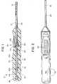
- a first hemostatic agent dispenser tool 10in accord with the invention is seen.
- the primary components of the tool 10a hollow tube 15 which holds and dispenses a plurality of individual units of the hemostatic agent 18 such as collagen, a valve 20, a plunger 25, and a mechanism 30 for moving the plunger distally in incremental movements.
- the valve 20can be of any of many types of check valves (e.g., slit valves, flapper valves, etc.), in accord with a preferred embodiment of the invention, as seen in Fig.
- valve 20is a substantially condom-shaped plastic valve, with a rounded end 31 which effectively closes off the distal opening 38 in the hollow tube, and a long sleeve 32.
- the rounded end 31 of the valve 20has a slit 33 therein, and is shaped to accommodate oblong pellets of collagen or other hemostatic agent 18 which are forced through the slit 33 as described hereinafter.
- the long sleeve 32 of the valve 20sits inside hollow tube 15, and preferably includes nubs or protrusions 34 which extend into holes 35 in the hollow tube 15 thereby holding the valve 20 in place.
- the long sleeve 32 of the valve 20is also bonded to the hollow tube 15 which may be formed of plastic or metal as desired. Regardless of the manner in which it is held in the hollow tube 15, valve 20 functions to permit the hamostatic agent 18 to pass therethrough and out of hollow tube 15, but prevents foreign matter (such as blood) from contacting the hemostatic agent 18 while it is in the hollow tube 15.
- the distal end 38 of the hollow tube 15is open.
- the proximal end 39 of the distal tubeis likewise open and is preferably insert molded into a handle 40.
- Handle 40as seen in Fig. 1 has a passage 42 which extends axially therethrough through which the collagen pellets 18 and the plunger 25 are loaded.
- Passage 42includes a narrower passage 42a which receives the hollow tube 15, and a slightly larger passage 42b which receives a spring 44 and a plug 46.
- Spring 44is fixed to plug 46 which plugs the proximal end of the handle 40 and also extends around and is fixed to the proximal end of the plunger 25.
- spring 44applies a force on the plunger 25 which prevents the plunger from accidentally discharging hemostatic agent pellets 18 by shaking or by sharp downwards movement.
- handle 40is preferably provided with finger grips 53 along its bottom surface. Also housed in handle 40 is the mechanism 30 for moving the plunger distally in incremental movements. Mechanism 30 is best understood with reference to Fig. 1a.
- mechanism 30is effectively a ratchet and pawl mechanism with the ratchet being integral with the plunger 25 as hereinafter described, and the pawl being coupled to a slide switch mechanism 60.
- the slide switch 60 mechanismincludes an external slide element 62 having nubs 63, a base element 64 which is fixedly attached to the slide element 62, a V-spring element 66, with one side of the V fixedly attached to the base of base element 64 and with free end 67 extending at an angle thereto, a finger 68 extending axially from the base element, and a coil spring 71 seated on the front of the base element 64 and extending around and past the finger 68.
- handle 40has a cutout 73 for the base, spring and finger elements of slide switch 60. The cutout also includes tunnel 76 into which the coil spring 68 extends and is affixed and into which finger 68 can extend when switch 60 is moved forward.
- the ratchet of the advancing mechanism 30is the formation in a proximal portion of the plunger of a series of conical shaped elements 84 which are preferably molded into the plunger during formation thereof.
- Each conical shaped elementhas a front distal portion which is of smaller diameter than its rear proximal portion.
- a seat 86is formed where the smaller distal portion of one conical element meets the larger proximal portion of another conical element.
- the free end 67 of the V-spring element 66 of slide switch 60is arranged to abut seat 86.
- V-spring 66acts as a pawl and pushes on seat 86 of plunger 25.
- the plunger 25moves forward, it pushes the capsules 18, and discharges a capsule 18 through valve 20.
- the finger 68 of the switch 60extends into tunnel 76, and spring 71 is compressed.
- the switch 60is forced backward by spring 68 (and/or by finger movement of the slide 62), and the end 67 of V-spring 66 rides up over the ramped conical surface of the adjacent cone element 84, coming to rest at a new seat 86.
- slide switch 60be moved forward again. Because the conical elements 84 are arranged to be the same size as the hemostatic agent units 18, each forward movement of slide switch 60 moves the plunger 25 incrementally, thereby discharging a single unit of hemostatic agent 18.
- tool 100parts which are the same as in tool 10 are provided with the same descriptive numbers, while parts which have similar function are provided with numbers one hundred removed from similar parts of tool 10.
- tool 100is provided with a tube 15, having a valve 20 at its distal end, a plunger 25, and a mechanism 130 for moving the plunger 25 in incremental movements.
- Mechanism 130is very similar to mechanism 30 in that it includes conical elements 84 on the plunger, and a spring 66 in housing 40 having a free end 67 which sets on the back face of the conical elements 84.
- tool 100is provided with a pistol type handle 140 with grips 153 and a trigger mechanism 160 having a trigger 162 which is pushed against spring 171 housed in tunnel 174.
- the trigger 162is pulled backward toward handle 140, the top portion 197 of the trigger 162 to which the spring 66 is coupled moves forward (distally) in the housing 40.
- This forward movementcauses spring end 67 to push the plunger 25 forward and cause a unit of hemostatic agent 18 to be pushed through valve 20.
- the trigger 152is pushed forward away from handle 140 by spring 171, and the top 197 of trigger moves backward (proximally).
- spring 66rides over its adjacent conical element 84 and seats in the next seat 86, with spring 88 ensuring that plunger 25 is not moved backward at the same time.
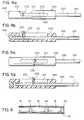
- mechanism 230 for moving a plunger 225 of a third embodiment 200 of the hemostatic agent delivery toolis seen in Figs, 4a, 4b, and 5a, and 5b (the distal end of tool 200 preferably being identical to the embodiments of Figs. 1-3).
- mechanism 230comprises the combination of a notched cutout 201 in the handle 240 of the tool 200 in conjunction with the proximal end portion of the plunger 225 which is provided with a knob or protrusion 202 which extends perpendicular to the plunger 225 and through cutout 201.
- the notched cutout 201is shaped with a plurality of resilient stops 205 (typically formed during molding) through which the knob 202 can be forced.
- Each notchis preferably the length of a unit of hemostatic agent.
- the tube 215extends through the housing 240 and is closed by stopper 246.
- tube 215must also have an opening through which knob 202 extends.
- the proximal end of tube 215can terminate at the distal end of the handle 240.
- a passage through the handleis then preferably provided so that the hemostatic agent and plunger may be loaded during assembly.
- Knob 202can be integrally formed with the plunger 225, or, as shown, can be attached to the plunger via the use of a screw 203 or the like which extends through the knob 202 and into the plunger 225.
- Knob 202is also preferably tapered such that it widens as it extends from its distal end to its proximal end. Because the cutout is notched with wider sections and narrower resilient stops 205, the tapering of knob 202 permits the knob 202 to be forced through the resilient stops 205 in the forward direction only; the tapering distal surface of knob 202 acting as a wedge to force resilient stops 205 open, but the flat proximal surface of knob 202 being unable to be forced through resilient stops 205.
- This arrangementeliminates the need for means for preventing backward movement of the plunger after each incremental movement of the plunger. It also eliminates the need for means for restraining forward movement of the plunger.
- hemostatic agent pelletsare shown in Figs. 1 and 1b and have been described for use with all of the embodiments, it will be appreciated that the "pellets" can take various forms.
- the pelletsmay be formed of molded hemostatic agent or may be made by rolling a sheet of hemostatic agent fiber.
- each unit 18 of hemostatic agentmay be separated by an attached or separate inert bioabsorbable or dissolvable spacer element 118.
- the function of spacer element 118is to protect the hemostatic agent unit 18 from contact with blood or other foreign material prior to dispensing.
- the inert spacer element 118may be used in conjunction with the valve 20 or may be used in lieu thereof as the protective mechanism for the hemostatic agent units 18.
- the pellet shapeis not necessarily advantageous.
- accountmust be taken for the total axial length of the spacer element and the hemostatic agent unit when determining the distance that the plunger must be incrementally moved.
- the tool of the inventionis adapted to apply individual units of a hemostatic agent to an internal bleeding site by moving the plunger in measured incremental movements in order to dispense the individual units of the hemostatic agent.
- knob and the notched cutoutwas shown as a knob with a tapered horizontal cross-section, and an alternately widening and narrowing cutout, it will be appreciated that different shaped knobs and cutouts could be effectively utilized to obtain the same desired results. It will therefore be appreciated by those skilled in the art that yet other modifications could be made to the provided invention without deviating from its scope as claimed.
- the surgical methodis for applying units of a haemostatic agent to an internal bleeding site using an endoscopic tool loaded with a plurality of discrete individual units of haemostatic agent said discrete individual units being of substantially identical size to each other.
- the endoscopic toolhas a hollow tube which holds the plurality of discrete individual units of the haemostatic agent, said hollow tube having proximal and distal ends with an opening in said distal end, a plunger which extends into the hollow tube and contacts a proximal unit of the haemostatic agent, and hand actuated movement means coupled to said plunger for moving said plunger distally in measured incremental movements.
- the plunger and said hand actuated movement meanstogether comprise ratchet means having means for preventing proximal movement of said plunger upon each said incremental movement.
- the method of using the toolcomprises further:
Landscapes
- Health & Medical Sciences (AREA)
- Engineering & Computer Science (AREA)
- Life Sciences & Earth Sciences (AREA)
- Animal Behavior & Ethology (AREA)
- Anesthesiology (AREA)
- Biomedical Technology (AREA)
- Heart & Thoracic Surgery (AREA)
- Hematology (AREA)
- Dermatology (AREA)
- Medical Informatics (AREA)
- General Health & Medical Sciences (AREA)
- Public Health (AREA)
- Veterinary Medicine (AREA)
- Surgical Instruments (AREA)
- Endoscopes (AREA)
- Infusion, Injection, And Reservoir Apparatuses (AREA)
Description
Claims (10)
- An endoscopic tool comprising:(a) a hollow tube (15) containing a plurality of discrete unitsof haemostatic agent (18), said hollow tube (15) havingproximal and distal ends (38, 39) with an opening in said distal end (38);(b) a plunger (25) which extends into the hollow tube (15) andcontacts a proximal unit of said haemostatic agent;(c) hand actuated movement means (30) coupled to said plunger (25)for moving said plunger (25) distally in measuredincremental movements to cause, upon each saidincremental movement, at least one of said discreteunits of said haemostatic agent to be pushed out ofsaid hollow tube (15) through said opening in said distalend (38) of said hollow tube (15), wherein said plunger (25)and said hand actuated movement means (30) together comprise aratchet means having means for preventing proximalmovement of said plunger (25) upon each said incrementalmovement, and(d) a valve (20) at said distal end of said hollow tube (15),said valve permitting said haemostatic agent (18) to passtherethrough but preventing foreign matter fromcontacting said haemostatic agent (18) while saidhaemostatic agent (18) is in said hollow tube (15).
- An endoscopic tool according to claim 1, furthercomprising:(e) a handle (40), said handle (40) housing said proximal end(39) of said hollow tube (15) and said hand actuated movementmeans (30).
- An endoscopic tool according to claim 1 or 2 furthercomprising:a plurality of spacer means (118) which are inert relative toblood, wherein said plurality of discrete units of saidhaemostatic agent (18) and said inert spacer means (118) are arrangedin a line with a first spacer means (118) at said distal end ofsaid hollow tube (15), followed by a first of said discreteunits of said haemostatic agent (18), followed by a secondspacer means (118), followed by a second of said discrete unitsof said haemostatic agent (18).
- An endoscopic tool according to any preceding claimwherein:said plunger (25) has a proximal portion having a plurality oframps (84) and seats (86), each said ramp (84) increasing in diameter asit extends proximally, and each said ramp (84) terminating in asaid seat (86), andsaid hand actuated movement means (30) comprises said proximalportion of said plunger (25) and a pawl means for contacting afirst seat (86) of said proximal portion of said plunger (25) and forpushing said first seat forward a predetermined distance.
- An endoscopic tool according to claim 4, wherein said pawlmeans comprises:( i) a switch having a finger-actuated portion and a V-springhaving a first portion coupled to said finger-actuatedportion and a second portion angled at anangle similar to said ramp (84) of said plunger (25) and havinga free end (67) contacting said first seat (86); or(ii) a slide switch (60) having a finger actuated slide element (62)external a surface of said handle (40) and a base element (64)coupled to said slide element (62) and located internallyof said surface of said handle (40), said slide switch (60)movable within said handle (40) from a first position to asecond position, and a V-spring (88) having one portion (66)fixedly coupled to said base element (64) of said slideswitch (60) and having a second portion with a free end (67),wherein movement of said slide switch (60) from said firstposition to said second position causes said free end (67)of said V-spring to push on a first seat (86) of saidproximal portion of said plunger (25) and push said plunger (25)distally a first predetermined distance, and movementof said slide switch (60) from said second position to saidfirst position causes said V-spring (88) to ride over anadjacent ramp (84) of said proximal portion of said plunger (25)and to set in a second seat of said proximal portionof said plunger (25).
- An endoscopic tool according to claim 5, wherein:said means for preventing proximal movement comprises meansfixed to said handle and unable to move relative thereto,said means fixed to said handle having means for engaginga seat of said proximal portion of said plunger.
- An endoscopic tool according to claim 4, wherein said pawlmeans comprises:a finger actuated trigger means (160) having a first portionwhich is external a surface of said handle (140) and a secondportion which is internal said surface of said handle (140), saidtrigger means being movable within and relative said handle (140)from a first position to a second position, and a V-spring (88)having one portion fixedly coupled to said second portionof said trigger means (160) and having a second portion with afree end, wherein movement of said trigger means (160) from saidfirst position to said second position causes said free endof said V-spring (88) to push on a first seat (86) of said proximalportion of said plunger (25) and push said plunger (25) distally afirst predetermined distance, and movement of said triggermeans (160) from said second position to said first positioncauses said free end of said V-spring (88) to ride over anadjacent ramp (84) of said proximal portion of said plunger (25) andto set in a second seat (84) of said proximal portion of saidplunger (25).
- An endoscopic tool according to any of claims 4 to 7wherein each said ramp (84) has an axial length substantiallyequal to the length of the unit of haemostatic agent.
- An endoscopic tool according to any of claims 1 to 8,wherein said hand actuated movement means comprises a cut-out(201) in said handle (240) having a plurality of resilientstops (205) and hand-grippable means (202) coupled to said plunger (225) andextending through said cut-out (201), said hand-grippable means (202)being shaped relative to said cut-out (201) such that said hand-grippablemeans (202) can be forced past said resilient stops (205) ofsaid handle (240).
- An endoscopic tool according to claim 9, wherein:said cut-out (201) in said handle (240) comprises a plurality ofnotches of wider diameter separated by said plurality ofresilient stops (205) of smaller diameter, and said hand-grippablemeans (202) comprises a knob (202) tapered down in crosssectionas it extends distally, wherein said knob (202) acts asa wedge for forcing through a resilient stop (205) as it ispushed distally, wherein each said notch typically has anaxial length substantially equal to the length of the unitof haemostatic agent, said plurality of notches typicallycomprising a number of equal to or greater than the numberof units of haemostatic agent contained in said tube.
Applications Claiming Priority (2)
| Application Number | Priority Date | Filing Date | Title |
|---|---|---|---|
| US07/919,893US5281197A (en) | 1992-07-27 | 1992-07-27 | Endoscopic hemostatic agent delivery system |
| US919893 | 1992-07-27 |
Publications (3)
| Publication Number | Publication Date |
|---|---|
| EP0584959A2 EP0584959A2 (en) | 1994-03-02 |
| EP0584959A3 EP0584959A3 (en) | 1994-04-27 |
| EP0584959B1true EP0584959B1 (en) | 1998-12-16 |
Family
ID=25442823
Family Applications (1)
| Application Number | Title | Priority Date | Filing Date |
|---|---|---|---|
| EP93305933AExpired - LifetimeEP0584959B1 (en) | 1992-07-27 | 1993-07-27 | Endoscopic haemostatic agent delivery system |
Country Status (4)
| Country | Link |
|---|---|
| US (1) | US5281197A (en) |
| EP (1) | EP0584959B1 (en) |
| CA (1) | CA2101304C (en) |
| DE (1) | DE69322559T2 (en) |
Cited By (7)
| Publication number | Priority date | Publication date | Assignee | Title |
|---|---|---|---|---|
| US8361067B2 (en) | 2002-09-30 | 2013-01-29 | Relievant Medsystems, Inc. | Methods of therapeutically heating a vertebral body to treat back pain |
| US8414571B2 (en) | 2010-01-07 | 2013-04-09 | Relievant Medsystems, Inc. | Vertebral bone navigation systems |
| US8419730B2 (en) | 2008-09-26 | 2013-04-16 | Relievant Medsystems, Inc. | Systems and methods for navigating an instrument through bone |
| US8425507B2 (en) | 2002-09-30 | 2013-04-23 | Relievant Medsystems, Inc. | Basivertebral nerve denervation |
| US8882764B2 (en) | 2003-03-28 | 2014-11-11 | Relievant Medsystems, Inc. | Thermal denervation devices |
| US12039731B2 (en) | 2020-12-22 | 2024-07-16 | Relievant Medsystems, Inc. | Prediction of candidates for spinal neuromodulation |
| US12433668B1 (en) | 2021-11-08 | 2025-10-07 | Relievant Medsystems, Inc. | Impedance stoppage mitigation during radiofrequency tissue ablation procedures |
Families Citing this family (202)
| Publication number | Priority date | Publication date | Assignee | Title |
|---|---|---|---|---|
| US5507754A (en)* | 1993-08-20 | 1996-04-16 | United States Surgical Corporation | Apparatus and method for applying and adjusting an anchoring device |
| US5399162A (en)* | 1994-02-23 | 1995-03-21 | Cselle; Edward | Automatic balling gun |
| US5484403A (en)* | 1994-04-05 | 1996-01-16 | Avid Marketing, Inc. | Hypodermic syringe for implanting solid objects |
| DE4413520A1 (en)* | 1994-04-19 | 1995-10-26 | Ruesch Willy Ag | Device for the controlled placement of a trocar or a puncture cannula |
| US6033401A (en)* | 1997-03-12 | 2000-03-07 | Advanced Closure Systems, Inc. | Vascular sealing device with microwave antenna |
| US6302898B1 (en) | 1994-06-24 | 2001-10-16 | Advanced Closure Systems, Inc. | Devices for sealing punctures in body vessels |
| US5595752A (en)* | 1994-07-01 | 1997-01-21 | Monsanto Company | Increasing dressing percentage and carcass weight in finishing beef cattle |
| US5672357A (en)* | 1994-07-01 | 1997-09-30 | Monsanto Company | Method and device for implantation of large diameter objects in bovines |
| DE9417574U1 (en)* | 1994-11-02 | 1996-03-07 | Neumann, Kurt, 91080 Uttenreuth | Medical device for introducing medical arrangements ect. through layers of tissue in the body |
| AT402683B (en)* | 1995-05-16 | 1997-07-25 | Hafslund Nycomed Pharma | DEVICE FOR ENDOSCOPIC OR LAPAROSCOPIC APPLICATION OF SURGICAL MATERIAL |
| AU7706196A (en)* | 1995-12-13 | 1997-07-03 | Nycomed Arzneimittel Gmbh | An instrument for the application of surgical material |
| DE19546434A1 (en)* | 1995-12-13 | 1997-06-19 | Nycomed Arzneimittel Gmbh | Instrument for application of wound sealing material |
| US5728132A (en)* | 1996-04-08 | 1998-03-17 | Tricardia, L.L.C. | Self-sealing vascular access device |
| US5820604A (en)* | 1996-06-11 | 1998-10-13 | Endolap, Inc. | Cannula cap including yeildable outer seal and flapper valve |
| US6066117A (en)* | 1996-06-11 | 2000-05-23 | Endolap, Inc. | Cannula flapper valve assembly |
| US6743248B2 (en) | 1996-12-18 | 2004-06-01 | Neomend, Inc. | Pretreatment method for enhancing tissue adhesion |
| US5906594A (en) | 1997-01-08 | 1999-05-25 | Symbiosis Corporation | Endoscopic infusion needle having dual distal stops |
| US6193670B1 (en) | 1997-02-14 | 2001-02-27 | Tricardia, Llc | Hemostatic agent delivery device having built-in pressure sensor |
| US5855559A (en)* | 1997-02-14 | 1999-01-05 | Tricardia, Inc. | Hemostatic agent delivery device having built-in pressure sensor |
| US6475182B1 (en) | 1997-03-12 | 2002-11-05 | Olexander Hnojewyj | Fluidic media introduction apparatus |
| US20040176801A1 (en)* | 1997-03-12 | 2004-09-09 | Neomend, Inc. | Pretreatment method for enhancing tissue adhesion |
| US20030191496A1 (en)* | 1997-03-12 | 2003-10-09 | Neomend, Inc. | Vascular sealing device with microwave antenna |
| US6733515B1 (en) | 1997-03-12 | 2004-05-11 | Neomend, Inc. | Universal introducer |
| US8668737B2 (en) | 1997-10-10 | 2014-03-11 | Senorx, Inc. | Tissue marking implant |
| US7637948B2 (en)* | 1997-10-10 | 2009-12-29 | Senorx, Inc. | Tissue marking implant |
| US6251418B1 (en)* | 1997-12-18 | 2001-06-26 | C.R. Bard, Inc. | Systems and methods for local delivery of an agent |
| US6161034A (en)* | 1999-02-02 | 2000-12-12 | Senorx, Inc. | Methods and chemical preparations for time-limited marking of biopsy sites |
| US6347241B2 (en)* | 1999-02-02 | 2002-02-12 | Senorx, Inc. | Ultrasonic and x-ray detectable biopsy site marker and apparatus for applying it |
| US6356782B1 (en)* | 1998-12-24 | 2002-03-12 | Vivant Medical, Inc. | Subcutaneous cavity marking device and method |
| US9669113B1 (en) | 1998-12-24 | 2017-06-06 | Devicor Medical Products, Inc. | Device and method for safe location and marking of a biopsy cavity |
| US6371904B1 (en) | 1998-12-24 | 2002-04-16 | Vivant Medical, Inc. | Subcutaneous cavity marking device and method |
| US6270472B1 (en)* | 1998-12-29 | 2001-08-07 | University Of Pittsburgh Of The Commonwealth System Of Higher Education | Apparatus and a method for automatically introducing implants into soft tissue with adjustable spacing |
| US20080039819A1 (en)* | 2006-08-04 | 2008-02-14 | Senorx, Inc. | Marker formed of starch or other suitable polysaccharide |
| US20090030309A1 (en)* | 2007-07-26 | 2009-01-29 | Senorx, Inc. | Deployment of polysaccharide markers |
| US6862470B2 (en) | 1999-02-02 | 2005-03-01 | Senorx, Inc. | Cavity-filling biopsy site markers |
| US8361082B2 (en)* | 1999-02-02 | 2013-01-29 | Senorx, Inc. | Marker delivery device with releasable plug |
| US7983734B2 (en)* | 2003-05-23 | 2011-07-19 | Senorx, Inc. | Fibrous marker and intracorporeal delivery thereof |
| US9820824B2 (en) | 1999-02-02 | 2017-11-21 | Senorx, Inc. | Deployment of polysaccharide markers for treating a site within a patent |
| US8498693B2 (en)* | 1999-02-02 | 2013-07-30 | Senorx, Inc. | Intracorporeal marker and marker delivery device |
| US7651505B2 (en)* | 2002-06-17 | 2010-01-26 | Senorx, Inc. | Plugged tip delivery for marker placement |
| US6725083B1 (en) | 1999-02-02 | 2004-04-20 | Senorx, Inc. | Tissue site markers for in VIVO imaging |
| US6575991B1 (en) | 1999-06-17 | 2003-06-10 | Inrad, Inc. | Apparatus for the percutaneous marking of a lesion |
| US6461356B1 (en)* | 1999-07-01 | 2002-10-08 | C.R. Bard, Inc. | Medical device having an incrementally displaceable electrode |
| US6855160B1 (en) | 1999-08-04 | 2005-02-15 | C. R. Bard, Inc. | Implant and agent delivery device |
| US6494896B1 (en) | 1999-11-30 | 2002-12-17 | Closure Medical Corporation | Applicator for laparoscopic or endoscopic surgery |
| US6450938B1 (en)* | 2000-03-21 | 2002-09-17 | Promex, Llc | Brachytherapy device |
| US7232421B1 (en) | 2000-05-12 | 2007-06-19 | C. R. Bard, Inc. | Agent delivery systems |
| AU2001292609A1 (en)* | 2000-09-11 | 2002-03-26 | Closure Medical Corporation | Bronchial occlusion method and apparatus |
| CA2659518A1 (en) | 2000-11-20 | 2002-05-30 | Senorx, Inc. | Tissue site markers for in vivo imaging |
| US6569077B2 (en)* | 2001-07-11 | 2003-05-27 | Bruno Schmidt | Dimpled seed implant needle |
| EP1507572B1 (en)* | 2002-05-17 | 2007-01-10 | Tyco Healthcare Group Lp | Wound closure material applicator |
| US6907884B2 (en) | 2002-09-30 | 2005-06-21 | Depay Acromed, Inc. | Method of straddling an intraosseous nerve |
| US7326203B2 (en)* | 2002-09-30 | 2008-02-05 | Depuy Acromed, Inc. | Device for advancing a functional element through tissue |
| US20070260267A1 (en)* | 2002-10-07 | 2007-11-08 | Nicoson Zachary R | Localizing obturator |
| US7347829B2 (en)* | 2002-10-07 | 2008-03-25 | Suros Surgical Systems, Inc. | Introduction system for minimally invasive surgical instruments |
| US20080161720A1 (en)* | 2002-10-07 | 2008-07-03 | Nicoson Zachary R | Registration system |
| US20060036158A1 (en)* | 2003-11-17 | 2006-02-16 | Inrad, Inc. | Self-contained, self-piercing, side-expelling marking apparatus |
| US20050119562A1 (en)* | 2003-05-23 | 2005-06-02 | Senorx, Inc. | Fibrous marker formed of synthetic polymer strands |
| US7877133B2 (en)* | 2003-05-23 | 2011-01-25 | Senorx, Inc. | Marker or filler forming fluid |
| AU2004263171B2 (en)* | 2003-08-07 | 2008-12-04 | Merit Medical Systems, Inc. | Therapeutic medical appliance, delivery and method of use |
| US8357103B2 (en) | 2003-10-14 | 2013-01-22 | Suros Surgical Systems, Inc. | Vacuum assisted biopsy needle set |
| US8048003B2 (en) | 2003-10-14 | 2011-11-01 | Suros Surgical Systems, Inc. | Vacuum assisted biopsy device |
| US7988642B2 (en)* | 2003-10-14 | 2011-08-02 | Suros Surgical Systems, Inc. | Vacuum assisted biopsy device |
| JP4500315B2 (en)* | 2003-10-14 | 2010-07-14 | シュロス・サージカル・システムズ・インコーポレーテッド | Vacuum assisted biopsy needle set |
| US20050273002A1 (en)* | 2004-06-04 | 2005-12-08 | Goosen Ryan L | Multi-mode imaging marker |
| WO2005072623A1 (en) | 2004-01-30 | 2005-08-11 | Ferrosan A/S | Haemostatic device |
| US20050234475A1 (en)* | 2004-03-04 | 2005-10-20 | Cordes Christopher J | Transponder implanter |
| US9638770B2 (en) | 2004-05-21 | 2017-05-02 | Devicor Medical Products, Inc. | MRI biopsy apparatus incorporating an imageable penetrating portion |
| US8932233B2 (en)* | 2004-05-21 | 2015-01-13 | Devicor Medical Products, Inc. | MRI biopsy device |
| US7708751B2 (en) | 2004-05-21 | 2010-05-04 | Ethicon Endo-Surgery, Inc. | MRI biopsy device |
| US7845536B2 (en) | 2004-10-18 | 2010-12-07 | Tyco Healthcare Group Lp | Annular adhesive structure |
| US7938307B2 (en) | 2004-10-18 | 2011-05-10 | Tyco Healthcare Group Lp | Support structures and methods of using the same |
| US7150709B1 (en)* | 2004-12-24 | 2006-12-19 | Bruno Schmidt | Wax-less implant system |
| US9364229B2 (en) | 2005-03-15 | 2016-06-14 | Covidien Lp | Circular anastomosis structures |
| US10357328B2 (en)* | 2005-04-20 | 2019-07-23 | Bard Peripheral Vascular, Inc. and Bard Shannon Limited | Marking device with retractable cannula |
| US20060282042A1 (en)* | 2005-06-08 | 2006-12-14 | Sensors For Medicine And Science, Inc. | Insertion device and method |
| US8052658B2 (en) | 2005-10-07 | 2011-11-08 | Bard Peripheral Vascular, Inc. | Drug-eluting tissue marker |
| US8349443B2 (en)* | 2006-02-23 | 2013-01-08 | Meadwestvaco Corporation | Method for treating a substrate |
| US7945307B2 (en)* | 2006-08-04 | 2011-05-17 | Senorx, Inc. | Marker delivery system with obturator |
| US20080294039A1 (en)* | 2006-08-04 | 2008-11-27 | Senorx, Inc. | Assembly with hemostatic and radiographically detectable pellets |
| US8430906B2 (en)* | 2006-09-29 | 2013-04-30 | St. Jude Medical, Cardiology Division, Inc. | Method and apparatus to promote hemostasis |
| WO2008051749A2 (en) | 2006-10-23 | 2008-05-02 | C. R. Bard, Inc. | Breast marker |
| US9579077B2 (en) | 2006-12-12 | 2017-02-28 | C.R. Bard, Inc. | Multiple imaging mode tissue marker |
| WO2008076973A2 (en) | 2006-12-18 | 2008-06-26 | C.R.Bard Inc. | Biopsy marker with in situ-generated imaging properties |
| US8038045B2 (en) | 2007-05-25 | 2011-10-18 | Tyco Healthcare Group Lp | Staple buttress retention system |
| US7665646B2 (en) | 2007-06-18 | 2010-02-23 | Tyco Healthcare Group Lp | Interlocking buttress material retention system |
| US8062330B2 (en) | 2007-06-27 | 2011-11-22 | Tyco Healthcare Group Lp | Buttress and surgical stapling apparatus |
| US7895151B2 (en)* | 2008-06-23 | 2011-02-22 | Teradata Us, Inc. | Fast bulk loading and incremental loading of data into a database |
| US8808200B2 (en) | 2007-10-01 | 2014-08-19 | Suros Surgical Systems, Inc. | Surgical device and method of using same |
| US8202229B2 (en)* | 2007-10-01 | 2012-06-19 | Suros Surgical Systems, Inc. | Surgical device |
| WO2009099767A2 (en) | 2008-01-31 | 2009-08-13 | C.R. Bard, Inc. | Biopsy tissue marker |
| US8361100B2 (en)* | 2008-03-17 | 2013-01-29 | Ethicon, Inc. | Applicator instruments for the delivery, deployment, and tamponade of hemostats and methods therefor |
| US20090247900A1 (en)* | 2008-03-25 | 2009-10-01 | Brian Zimmer | Push button adjustable spacer |
| US20090247901A1 (en)* | 2008-03-25 | 2009-10-01 | Brian Zimmer | Latching side removal spacer |
| US8366733B2 (en)* | 2008-03-28 | 2013-02-05 | Ethicon, Inc. | Applicator instruments for controlling bleeding at surgical sites and methods therefor |
| US8043316B2 (en)* | 2008-05-02 | 2011-10-25 | Suros Surgical Systems, Inc. | Adjustable spacer |
| BRPI0913380A2 (en) | 2008-06-04 | 2015-11-24 | Neovista Inc | portable radiation release system for advancing a radiation source wire |
| US7824359B2 (en)* | 2008-07-24 | 2010-11-02 | Solomon Clifford T | Bioinjection device |
| US9327061B2 (en) | 2008-09-23 | 2016-05-03 | Senorx, Inc. | Porous bioabsorbable implant |
| US10028753B2 (en) | 2008-09-26 | 2018-07-24 | Relievant Medsystems, Inc. | Spine treatment kits |
| BRPI0917035A2 (en)* | 2008-12-04 | 2019-09-24 | Pivot Medical Inc | "telescope access cannula, telescope shutter, system, method for providing an access corridor from a first off-site location to a second on-site location" |
| US20100147921A1 (en) | 2008-12-16 | 2010-06-17 | Lee Olson | Surgical Apparatus Including Surgical Buttress |
| EP4215147A3 (en) | 2008-12-30 | 2023-10-18 | C. R. Bard, Inc. | Marker delivery device for tissue marker placement |
| US7967179B2 (en) | 2009-03-31 | 2011-06-28 | Tyco Healthcare Group Lp | Center cinch and release of buttress material |
| US9486215B2 (en) | 2009-03-31 | 2016-11-08 | Covidien Lp | Surgical stapling apparatus |
| CA2757870C (en)* | 2009-04-30 | 2016-02-02 | Cook Medical Technologies Llc | System and method for fiducial deployment |
| CA2768849A1 (en) | 2009-07-21 | 2011-01-27 | Leonard V. Covello | Devices and methods for minimally invasive access to sinuses and treatment of sinusitis |
| US10842485B2 (en) | 2009-10-15 | 2020-11-24 | Covidien Lp | Brachytherapy buttress |
| US20150231409A1 (en) | 2009-10-15 | 2015-08-20 | Covidien Lp | Buttress brachytherapy and integrated staple line markers for margin identification |
| US9693772B2 (en) | 2009-10-15 | 2017-07-04 | Covidien Lp | Staple line reinforcement for anvil and cartridge |
| US9072542B2 (en)* | 2009-12-18 | 2015-07-07 | Cook Medical Technologies Llc | System and method for fiducial deployment |
| US10231721B2 (en) | 2010-06-24 | 2019-03-19 | St. Croix Surgical Systems, Llc | Failsafe percutaneous wound barrier |
| US9084602B2 (en)* | 2011-01-26 | 2015-07-21 | Covidien Lp | Buttress film with hemostatic action for surgical stapling apparatus |
| US9233238B2 (en)* | 2011-02-23 | 2016-01-12 | Ams Research Corporation | Drug releasing pelvic treatment system and method |
| US8789737B2 (en) | 2011-04-27 | 2014-07-29 | Covidien Lp | Circular stapler and staple line reinforcement material |
| US8838208B2 (en) | 2011-06-28 | 2014-09-16 | Cook Medical Technologies Llc | Fiducial deployment needle system |
| US8702742B2 (en)* | 2011-10-21 | 2014-04-22 | Synergetics, Inc. | Trocar system having a drive |
| US9675351B2 (en) | 2011-10-26 | 2017-06-13 | Covidien Lp | Buttress release from surgical stapler by knife pushing |
| US9610398B2 (en) | 2011-11-22 | 2017-04-04 | Incube Labs, Llc | Implantable solid-liquid drug delivery apparatus, formulations, and methods of use |
| US8967448B2 (en) | 2011-12-14 | 2015-03-03 | Covidien Lp | Surgical stapling apparatus including buttress attachment via tabs |
| US9351731B2 (en) | 2011-12-14 | 2016-05-31 | Covidien Lp | Surgical stapling apparatus including releasable surgical buttress |
| US9237892B2 (en) | 2011-12-14 | 2016-01-19 | Covidien Lp | Buttress attachment to the cartridge surface |
| AU2012362524B2 (en) | 2011-12-30 | 2018-12-13 | Relievant Medsystems, Inc. | Systems and methods for treating back pain |
| US9326773B2 (en) | 2012-01-26 | 2016-05-03 | Covidien Lp | Surgical device including buttress material |
| US9010609B2 (en) | 2012-01-26 | 2015-04-21 | Covidien Lp | Circular stapler including buttress |
| US20140048580A1 (en) | 2012-08-20 | 2014-02-20 | Covidien Lp | Buttress attachment features for surgical stapling apparatus |
| US10588691B2 (en) | 2012-09-12 | 2020-03-17 | Relievant Medsystems, Inc. | Radiofrequency ablation of tissue within a vertebral body |
| US9161753B2 (en) | 2012-10-10 | 2015-10-20 | Covidien Lp | Buttress fixation for a circular stapler |
| WO2014071161A1 (en) | 2012-11-05 | 2014-05-08 | Relievant Medsystems, Inc. | System and methods for creating curved paths through bone and modulating nerves within the bone |
| US20140131418A1 (en) | 2012-11-09 | 2014-05-15 | Covidien Lp | Surgical Stapling Apparatus Including Buttress Attachment |
| US9681936B2 (en) | 2012-11-30 | 2017-06-20 | Covidien Lp | Multi-layer porous film material |
| US9295466B2 (en) | 2012-11-30 | 2016-03-29 | Covidien Lp | Surgical apparatus including surgical buttress |
| US9402627B2 (en) | 2012-12-13 | 2016-08-02 | Covidien Lp | Folded buttress for use with a surgical apparatus |
| US9433420B2 (en) | 2013-01-23 | 2016-09-06 | Covidien Lp | Surgical apparatus including surgical buttress |
| US9192383B2 (en) | 2013-02-04 | 2015-11-24 | Covidien Lp | Circular stapling device including buttress material |
| US9414839B2 (en) | 2013-02-04 | 2016-08-16 | Covidien Lp | Buttress attachment for circular stapling device |
| US9504470B2 (en) | 2013-02-25 | 2016-11-29 | Covidien Lp | Circular stapling device with buttress |
| US9522264B2 (en) | 2013-02-26 | 2016-12-20 | Cook Medical Technologies Llc | Ratchet-slide handle and system for fiducial deployment |
| US20140239047A1 (en) | 2013-02-28 | 2014-08-28 | Covidien Lp | Adherence concepts for non-woven absorbable felt buttresses |
| US9782173B2 (en) | 2013-03-07 | 2017-10-10 | Covidien Lp | Circular stapling device including buttress release mechanism |
| US9775696B1 (en)* | 2013-03-25 | 2017-10-03 | Robert Zamora | Device to administer a solid animal medicine to an animal |
| US9724151B2 (en) | 2013-08-08 | 2017-08-08 | Relievant Medsystems, Inc. | Modulating nerves within bone using bone fasteners |
| US9855416B1 (en)* | 2013-08-21 | 2018-01-02 | Rhythmlink International Llc | Magazine holding plural electrode-carrying applicators |
| USD715942S1 (en) | 2013-09-24 | 2014-10-21 | C. R. Bard, Inc. | Tissue marker for intracorporeal site identification |
| USD716451S1 (en) | 2013-09-24 | 2014-10-28 | C. R. Bard, Inc. | Tissue marker for intracorporeal site identification |
| USD715442S1 (en) | 2013-09-24 | 2014-10-14 | C. R. Bard, Inc. | Tissue marker for intracorporeal site identification |
| USD716450S1 (en) | 2013-09-24 | 2014-10-28 | C. R. Bard, Inc. | Tissue marker for intracorporeal site identification |
| EP3151764B1 (en) | 2014-06-09 | 2023-02-01 | Cook Medical Technologies LLC | Screw-driven handles and systems for fiducial deployment |
| JP6302573B2 (en) | 2014-06-16 | 2018-03-28 | クック・メディカル・テクノロジーズ・リミテッド・ライアビリティ・カンパニーCook Medical Technologies Llc | Plunger-driven collet handle and fiducial deployment system |
| AU2015355303B2 (en) | 2014-12-03 | 2018-11-01 | Cook Medical Technologies Llc | Endoscopic ultrasound fiducial needle stylet handle assembly |
| WO2016164189A1 (en)* | 2015-04-09 | 2016-10-13 | Cleveland Kenneth Edwards | Hormone or other pellet delivery device |
| US10485577B2 (en) | 2016-02-18 | 2019-11-26 | Synergetics Usa, Inc. | Surgical device with triggered propulsion system for inserting a trocar-cannula assembly |
| US11382657B2 (en) | 2016-02-18 | 2022-07-12 | Synergetics Usa, Inc. | Surgical devices with triggered propulsion system for inserting a trocar-cannula assembly |
| US10959731B2 (en) | 2016-06-14 | 2021-03-30 | Covidien Lp | Buttress attachment for surgical stapling instrument |
| US11026686B2 (en) | 2016-11-08 | 2021-06-08 | Covidien Lp | Structure for attaching buttress to anvil and/or cartridge of surgical stapling instrument |
| US10874768B2 (en) | 2017-01-20 | 2020-12-29 | Covidien Lp | Drug eluting medical device |
| US10925607B2 (en) | 2017-02-28 | 2021-02-23 | Covidien Lp | Surgical stapling apparatus with staple sheath |
| US10368868B2 (en) | 2017-03-09 | 2019-08-06 | Covidien Lp | Structure for attaching buttress material to anvil and cartridge of surgical stapling instrument |
| US11096610B2 (en) | 2017-03-28 | 2021-08-24 | Covidien Lp | Surgical implants including sensing fibers |
| US10849625B2 (en) | 2017-08-07 | 2020-12-01 | Covidien Lp | Surgical buttress retention systems for surgical stapling apparatus |
| US10888693B2 (en)* | 2017-08-22 | 2021-01-12 | Warsaw Orthopedic, Inc. | Drug pellet injector needle and method |
| US10945733B2 (en) | 2017-08-23 | 2021-03-16 | Covidien Lp | Surgical buttress reload and tip attachment assemblies for surgical stapling apparatus |
| US11141151B2 (en) | 2017-12-08 | 2021-10-12 | Covidien Lp | Surgical buttress for circular stapling |
| US11065000B2 (en) | 2018-02-22 | 2021-07-20 | Covidien Lp | Surgical buttresses for surgical stapling apparatus |
| FR3080290B1 (en)* | 2018-04-18 | 2021-10-29 | Nemera La Verpilliere | IMPLANT INJECTION DEVICE WITH SEQUENTIAL RELEASE PUSHING MEANS |
| US10758237B2 (en) | 2018-04-30 | 2020-09-01 | Covidien Lp | Circular stapling apparatus with pinned buttress |
| US11426163B2 (en) | 2018-05-09 | 2022-08-30 | Covidien Lp | Universal linear surgical stapling buttress |
| US11432818B2 (en) | 2018-05-09 | 2022-09-06 | Covidien Lp | Surgical buttress assemblies |
| US11284896B2 (en) | 2018-05-09 | 2022-03-29 | Covidien Lp | Surgical buttress loading and attaching/detaching assemblies |
| US20210260303A1 (en)* | 2018-06-14 | 2021-08-26 | Sanofi | Medication delivery device and medication delivery assembly |
| US11219460B2 (en) | 2018-07-02 | 2022-01-11 | Covidien Lp | Surgical stapling apparatus with anvil buttress |
| US10806459B2 (en) | 2018-09-14 | 2020-10-20 | Covidien Lp | Drug patterned reinforcement material for circular anastomosis |
| US10952729B2 (en) | 2018-10-03 | 2021-03-23 | Covidien Lp | Universal linear buttress retention/release assemblies and methods |
| US11446059B2 (en)* | 2018-10-15 | 2022-09-20 | Boston Scientific Scimed, Inc. | Implant insertion device |
| CN109364355B (en)* | 2018-11-13 | 2021-04-06 | 蚌埠医学院第一附属医院 | A portable throat spray bottle |
| US11730472B2 (en) | 2019-04-25 | 2023-08-22 | Covidien Lp | Surgical system and surgical loading units thereof |
| JP7499272B2 (en)* | 2019-04-30 | 2024-06-13 | ボストン サイエンティフィック サイムド,インコーポレイテッド | Endoscopic Patch Applicator |
| US11478245B2 (en) | 2019-05-08 | 2022-10-25 | Covidien Lp | Surgical stapling device |
| US11596403B2 (en) | 2019-05-08 | 2023-03-07 | Covidien Lp | Surgical stapling device |
| US11969169B2 (en) | 2019-09-10 | 2024-04-30 | Covidien Lp | Anvil buttress loading unit for a surgical stapling apparatus |
| AU2020346827A1 (en) | 2019-09-12 | 2022-03-31 | Relievant Medsystems, Inc. | Systems and methods for tissue modulation |
| US11571208B2 (en) | 2019-10-11 | 2023-02-07 | Covidien Lp | Surgical buttress loading units |
| CA3157593A1 (en)* | 2019-11-21 | 2021-05-27 | Gust H. Bardy | Insertable physiological monitor injector tool |
| US11523824B2 (en) | 2019-12-12 | 2022-12-13 | Covidien Lp | Anvil buttress loading for a surgical stapling apparatus |
| US11547407B2 (en) | 2020-03-19 | 2023-01-10 | Covidien Lp | Staple line reinforcement for surgical stapling apparatus |
| CA3175862A1 (en) | 2020-03-24 | 2021-09-30 | Boston Scientific Scimed, Inc. | Agent delivery systems and methods of using the same |
| US11337699B2 (en) | 2020-04-28 | 2022-05-24 | Covidien Lp | Magnesium infused surgical buttress for surgical stapler |
| WO2021234611A2 (en)* | 2020-05-20 | 2021-11-25 | Boston Scientific Limited | Medical delivery systems and methods of using the same |
| US11707276B2 (en) | 2020-09-08 | 2023-07-25 | Covidien Lp | Surgical buttress assemblies and techniques for surgical stapling |
| US12082876B1 (en) | 2020-09-28 | 2024-09-10 | Relievant Medsystems, Inc. | Introducer drill |
| US11399833B2 (en) | 2020-10-19 | 2022-08-02 | Covidien Lp | Anvil buttress attachment for surgical stapling apparatus |
| US11534170B2 (en) | 2021-01-04 | 2022-12-27 | Covidien Lp | Anvil buttress attachment for surgical stapling apparatus |
| US11596399B2 (en) | 2021-06-23 | 2023-03-07 | Covidien Lp | Anvil buttress attachment for surgical stapling apparatus |
| US11510670B1 (en) | 2021-06-23 | 2022-11-29 | Covidien Lp | Buttress attachment for surgical stapling apparatus |
| US11672538B2 (en) | 2021-06-24 | 2023-06-13 | Covidien Lp | Surgical stapling device including a buttress retention assembly |
| US11678879B2 (en) | 2021-07-01 | 2023-06-20 | Covidien Lp | Buttress attachment for surgical stapling apparatus |
| US11684368B2 (en) | 2021-07-14 | 2023-06-27 | Covidien Lp | Surgical stapling device including a buttress retention assembly |
| US12076013B2 (en) | 2021-08-03 | 2024-09-03 | Covidien Lp | Surgical buttress attachment assemblies for surgical stapling apparatus |
| US11801052B2 (en) | 2021-08-30 | 2023-10-31 | Covidien Lp | Assemblies for surgical stapling instruments |
| US11751875B2 (en) | 2021-10-13 | 2023-09-12 | Coviden Lp | Surgical buttress attachment assemblies for surgical stapling apparatus |
| US11806017B2 (en) | 2021-11-23 | 2023-11-07 | Covidien Lp | Anvil buttress loading system for surgical stapling apparatus |
| EP4482400A1 (en) | 2022-02-24 | 2025-01-01 | Covidien LP | Surgical medical devices |
Family Cites Families (15)
| Publication number | Priority date | Publication date | Assignee | Title |
|---|---|---|---|---|
| GB638223A (en)* | 1940-06-01 | 1950-06-07 | American Cystoscope Makers Inc | Improvements in or relating to implanting devices |
| GB651524A (en)* | 1948-03-11 | 1951-04-04 | Raymond Mather | Improvements in or relating to balling guns |
| US2718299A (en)* | 1950-06-01 | 1955-09-20 | Verne L Atwater | Medicinal dispenser |
| US3110310A (en)* | 1961-07-20 | 1963-11-12 | Ideal Instr & Mfg Co Inc | Metering hypodermic syringe |
| GB1525841A (en)* | 1976-05-18 | 1978-09-20 | Hundon Forge Ltd | Drug implanters |
| US4086914A (en)* | 1977-02-11 | 1978-05-02 | Edwin Bailey Moore | Implant injector |
| US4361150A (en)* | 1980-04-07 | 1982-11-30 | Voss Joseph A | Extruded plastic hygienic applicator |
| US4406654A (en)* | 1982-02-22 | 1983-09-27 | American Cyanamid Company | Adjustable feeding device for the administration of dosages of gels and pastes to farm animals |
| US4700692A (en)* | 1985-12-23 | 1987-10-20 | Baumgartner George C | Surgical implantation method and apparatus |
| US4846793A (en)* | 1987-03-18 | 1989-07-11 | Endocon, Inc. | Injector for implanting multiple pellet medicaments |
| US4790819A (en)* | 1987-08-24 | 1988-12-13 | American Cyanamid Company | Fibrin clot delivery device and method |
| GB2240718A (en)* | 1990-02-09 | 1991-08-14 | Hundon Forge Ltd | Implanting device with needle cover |
| US5021059A (en)* | 1990-05-07 | 1991-06-04 | Kensey Nash Corporation | Plug device with pulley for sealing punctures in tissue and methods of use |
| WO1992020312A1 (en)* | 1991-05-21 | 1992-11-26 | Medchem Products, Inc. | Assembly and method for applying hemostatic agents |
| US5222939A (en)* | 1992-04-09 | 1993-06-29 | Jonathan Tiefenbrun | Instrument and associated method for applying biologically effective composition during surgery |
- 1992
- 1992-07-27USUS07/919,893patent/US5281197A/ennot_activeExpired - Lifetime
- 1993
- 1993-07-26CACA002101304Apatent/CA2101304C/ennot_activeExpired - Fee Related
- 1993-07-27DEDE69322559Tpatent/DE69322559T2/ennot_activeExpired - Fee Related
- 1993-07-27EPEP93305933Apatent/EP0584959B1/ennot_activeExpired - Lifetime
Cited By (23)
| Publication number | Priority date | Publication date | Assignee | Title |
|---|---|---|---|---|
| US8613744B2 (en) | 2002-09-30 | 2013-12-24 | Relievant Medsystems, Inc. | Systems and methods for navigating an instrument through bone |
| US8992522B2 (en) | 2002-09-30 | 2015-03-31 | Relievant Medsystems, Inc. | Back pain treatment methods |
| US8419731B2 (en) | 2002-09-30 | 2013-04-16 | Relievant Medsystems, Inc. | Methods of treating back pain |
| US9421064B2 (en) | 2002-09-30 | 2016-08-23 | Relievant Medsystems, Inc. | Nerve modulation systems |
| US8425507B2 (en) | 2002-09-30 | 2013-04-23 | Relievant Medsystems, Inc. | Basivertebral nerve denervation |
| US9173676B2 (en) | 2002-09-30 | 2015-11-03 | Relievant Medsystems, Inc. | Nerve modulation methods |
| US8628528B2 (en) | 2002-09-30 | 2014-01-14 | Relievant Medsystems, Inc. | Vertebral denervation |
| US9023038B2 (en) | 2002-09-30 | 2015-05-05 | Relievant Medsystems, Inc. | Denervation methods |
| US9486279B2 (en) | 2002-09-30 | 2016-11-08 | Relievant Medsystems, Inc. | Intraosseous nerve treatment |
| US8361067B2 (en) | 2002-09-30 | 2013-01-29 | Relievant Medsystems, Inc. | Methods of therapeutically heating a vertebral body to treat back pain |
| US9017325B2 (en) | 2002-09-30 | 2015-04-28 | Relievant Medsystems, Inc. | Nerve modulation systems |
| US8992523B2 (en) | 2002-09-30 | 2015-03-31 | Relievant Medsystems, Inc. | Vertebral treatment |
| US8623014B2 (en) | 2002-09-30 | 2014-01-07 | Relievant Medsystems, Inc. | Systems for denervation of basivertebral nerves |
| US8882764B2 (en) | 2003-03-28 | 2014-11-11 | Relievant Medsystems, Inc. | Thermal denervation devices |
| US9039701B2 (en) | 2008-09-26 | 2015-05-26 | Relievant Medsystems, Inc. | Channeling paths into bone |
| US8808284B2 (en) | 2008-09-26 | 2014-08-19 | Relievant Medsystems, Inc. | Systems for navigating an instrument through bone |
| US9259241B2 (en) | 2008-09-26 | 2016-02-16 | Relievant Medsystems, Inc. | Methods of treating nerves within bone using fluid |
| US9265522B2 (en) | 2008-09-26 | 2016-02-23 | Relievant Medsystems, Inc. | Methods for navigating an instrument through bone |
| US8419730B2 (en) | 2008-09-26 | 2013-04-16 | Relievant Medsystems, Inc. | Systems and methods for navigating an instrument through bone |
| US8535309B2 (en) | 2010-01-07 | 2013-09-17 | Relievant Medsystems, Inc. | Vertebral bone channeling systems |
| US8414571B2 (en) | 2010-01-07 | 2013-04-09 | Relievant Medsystems, Inc. | Vertebral bone navigation systems |
| US12039731B2 (en) | 2020-12-22 | 2024-07-16 | Relievant Medsystems, Inc. | Prediction of candidates for spinal neuromodulation |
| US12433668B1 (en) | 2021-11-08 | 2025-10-07 | Relievant Medsystems, Inc. | Impedance stoppage mitigation during radiofrequency tissue ablation procedures |
Also Published As
| Publication number | Publication date |
|---|---|
| DE69322559T2 (en) | 1999-05-06 |
| DE69322559D1 (en) | 1999-01-28 |
| CA2101304C (en) | 2005-07-05 |
| CA2101304A1 (en) | 1994-01-28 |
| EP0584959A3 (en) | 1994-04-27 |
| US5281197A (en) | 1994-01-25 |
| EP0584959A2 (en) | 1994-03-02 |
Similar Documents
| Publication | Publication Date | Title |
|---|---|---|
| EP0584959B1 (en) | Endoscopic haemostatic agent delivery system | |
| US5415335A (en) | Surgical stapler cartridge containing lockout mechanism | |
| US6010513A (en) | Device for installing a tissue fastener | |
| CA2063238C (en) | Laparoscopic stapler with knife means | |
| US5312333A (en) | Endoscopic material delivery device | |
| US5389102A (en) | Apparatus and method for subcuticular stapling of body tissue | |
| US5279555A (en) | Device for injecting implants | |
| US9757552B2 (en) | Applicator for inserting an implant | |
| AU614678B2 (en) | Surgical stapler cartridge lockout device | |
| CA1125615A (en) | Multi-clip cartridge for repeating hemostatic clip applying instrument | |
| CA2495621C (en) | Methods and apparatus for delivery of ocular implants | |
| KR100546982B1 (en) | Subcutaneous Implants | |
| US7169133B2 (en) | Injection device with lockable dosing member | |
| US20040215133A1 (en) | Apparatus for delivery of ocular implants | |
| EP0594003A1 (en) | Apparatus for applying surgical clips | |
| WO2006071554A2 (en) | Improved apparatus for delivery of ocular implants | |
| JPH01113037A (en) | Staple cartridge and stapler for surgery | |
| HU216387B (en) | Device and method for implanting implant containing implant | |
| AU2023200759A1 (en) | Drug delivery device with pre-assembled cartridge | |
| CN117597094A (en) | Insert system for rod implants and methods of use | |
| US12109372B2 (en) | Agent delivery devices | |
| EP1033939B1 (en) | Device for installing a tissue fastener | |
| US5938101A (en) | Skin stapler with movable anvil | |
| US20200214818A1 (en) | Device, method, and system for automated dispensing of periodontal medication |
Legal Events
| Date | Code | Title | Description |
|---|---|---|---|
| PUAI | Public reference made under article 153(3) epc to a published international application that has entered the european phase | Free format text:ORIGINAL CODE: 0009012 | |
| AK | Designated contracting states | Kind code of ref document:A2 Designated state(s):BE CH DE ES FR GB IE IT LI NL | |
| PUAL | Search report despatched | Free format text:ORIGINAL CODE: 0009013 | |
| AK | Designated contracting states | Kind code of ref document:A3 Designated state(s):BE CH DE ES FR GB IE IT LI NL | |
| 17P | Request for examination filed | Effective date:19940924 | |
| 17Q | First examination report despatched | Effective date:19951208 | |
| GRAG | Despatch of communication of intention to grant | Free format text:ORIGINAL CODE: EPIDOS AGRA | |
| GRAG | Despatch of communication of intention to grant | Free format text:ORIGINAL CODE: EPIDOS AGRA | |
| GRAH | Despatch of communication of intention to grant a patent | Free format text:ORIGINAL CODE: EPIDOS IGRA | |
| GRAH | Despatch of communication of intention to grant a patent | Free format text:ORIGINAL CODE: EPIDOS IGRA | |
| GRAA | (expected) grant | Free format text:ORIGINAL CODE: 0009210 | |
| AK | Designated contracting states | Kind code of ref document:B1 Designated state(s):BE CH DE ES FR GB IE IT LI NL | |
| PG25 | Lapsed in a contracting state [announced via postgrant information from national office to epo] | Ref country code:NL Free format text:LAPSE BECAUSE OF FAILURE TO SUBMIT A TRANSLATION OF THE DESCRIPTION OR TO PAY THE FEE WITHIN THE PRESCRIBED TIME-LIMIT Effective date:19981216 Ref country code:LI Free format text:LAPSE BECAUSE OF FAILURE TO SUBMIT A TRANSLATION OF THE DESCRIPTION OR TO PAY THE FEE WITHIN THE PRESCRIBED TIME-LIMIT Effective date:19981216 Ref country code:IT Free format text:LAPSE BECAUSE OF FAILURE TO SUBMIT A TRANSLATION OF THE DESCRIPTION OR TO PAY THE FEE WITHIN THE PRE;WARNING: LAPSES OF ITALIAN PATENTS WITH EFFECTIVE DATE BEFORE 2007 MAY HAVE OCCURRED AT ANY TIME BEFORE 2007. THE CORRECT EFFECTIVE DATE MAY BE DIFFERENT FROM THE ONE RECORDED.SCRIBED TIME-LIMIT Effective date:19981216 Ref country code:ES Free format text:THE PATENT HAS BEEN ANNULLED BY A DECISION OF A NATIONAL AUTHORITY Effective date:19981216 Ref country code:CH Free format text:LAPSE BECAUSE OF FAILURE TO SUBMIT A TRANSLATION OF THE DESCRIPTION OR TO PAY THE FEE WITHIN THE PRESCRIBED TIME-LIMIT Effective date:19981216 Ref country code:BE Free format text:LAPSE BECAUSE OF FAILURE TO SUBMIT A TRANSLATION OF THE DESCRIPTION OR TO PAY THE FEE WITHIN THE PRESCRIBED TIME-LIMIT Effective date:19981216 | |
| REG | Reference to a national code | Ref country code:CH Ref legal event code:EP | |
| REF | Corresponds to: | Ref document number:69322559 Country of ref document:DE Date of ref document:19990128 | |
| REG | Reference to a national code | Ref country code:IE Ref legal event code:FG4D | |
| ET | Fr: translation filed | ||
| NLV1 | Nl: lapsed or annulled due to failure to fulfill the requirements of art. 29p and 29m of the patents act | ||
| REG | Reference to a national code | Ref country code:CH Ref legal event code:PL | |
| PLBE | No opposition filed within time limit | Free format text:ORIGINAL CODE: 0009261 | |
| STAA | Information on the status of an ep patent application or granted ep patent | Free format text:STATUS: NO OPPOSITION FILED WITHIN TIME LIMIT | |
| 26N | No opposition filed | ||
| REG | Reference to a national code | Ref country code:GB Ref legal event code:IF02 | |
| PGFP | Annual fee paid to national office [announced via postgrant information from national office to epo] | Ref country code:GB Payment date:20060614 Year of fee payment:14 | |
| PGFP | Annual fee paid to national office [announced via postgrant information from national office to epo] | Ref country code:FR Payment date:20060705 Year of fee payment:14 | |
| PGFP | Annual fee paid to national office [announced via postgrant information from national office to epo] | Ref country code:IE Payment date:20060720 Year of fee payment:14 | |
| PGFP | Annual fee paid to national office [announced via postgrant information from national office to epo] | Ref country code:DE Payment date:20060731 Year of fee payment:14 | |
| GBPC | Gb: european patent ceased through non-payment of renewal fee | Effective date:20070727 | |
| PG25 | Lapsed in a contracting state [announced via postgrant information from national office to epo] | Ref country code:DE Free format text:LAPSE BECAUSE OF NON-PAYMENT OF DUE FEES Effective date:20080201 | |
| REG | Reference to a national code | Ref country code:IE Ref legal event code:MM4A | |
| PG25 | Lapsed in a contracting state [announced via postgrant information from national office to epo] | Ref country code:GB Free format text:LAPSE BECAUSE OF NON-PAYMENT OF DUE FEES Effective date:20070727 | |
| REG | Reference to a national code | Ref country code:FR Ref legal event code:ST Effective date:20080331 | |
| PG25 | Lapsed in a contracting state [announced via postgrant information from national office to epo] | Ref country code:FR Free format text:LAPSE BECAUSE OF NON-PAYMENT OF DUE FEES Effective date:20070731 | |
| PG25 | Lapsed in a contracting state [announced via postgrant information from national office to epo] | Ref country code:IE Free format text:LAPSE BECAUSE OF NON-PAYMENT OF DUE FEES Effective date:20070727 |