EP0584090B1 - Four wheel drive hybrid vehicle - Google Patents
Four wheel drive hybrid vehicleDownload PDFInfo
- Publication number
- EP0584090B1 EP0584090B1EP92908028AEP92908028AEP0584090B1EP 0584090 B1EP0584090 B1EP 0584090B1EP 92908028 AEP92908028 AEP 92908028AEP 92908028 AEP92908028 AEP 92908028AEP 0584090 B1EP0584090 B1EP 0584090B1
- Authority
- EP
- European Patent Office
- Prior art keywords
- electric motor
- cardan shaft
- permanent
- motor
- wheel drive
- Prior art date
- Legal status (The legal status is an assumption and is not a legal conclusion. Google has not performed a legal analysis and makes no representation as to the accuracy of the status listed.)
- Expired - Lifetime
Links
Images
Classifications
- B—PERFORMING OPERATIONS; TRANSPORTING
- B60—VEHICLES IN GENERAL
- B60K—ARRANGEMENT OR MOUNTING OF PROPULSION UNITS OR OF TRANSMISSIONS IN VEHICLES; ARRANGEMENT OR MOUNTING OF PLURAL DIVERSE PRIME-MOVERS IN VEHICLES; AUXILIARY DRIVES FOR VEHICLES; INSTRUMENTATION OR DASHBOARDS FOR VEHICLES; ARRANGEMENTS IN CONNECTION WITH COOLING, AIR INTAKE, GAS EXHAUST OR FUEL SUPPLY OF PROPULSION UNITS IN VEHICLES
- B60K6/00—Arrangement or mounting of plural diverse prime-movers for mutual or common propulsion, e.g. hybrid propulsion systems comprising electric motors and internal combustion engines
- B60K6/20—Arrangement or mounting of plural diverse prime-movers for mutual or common propulsion, e.g. hybrid propulsion systems comprising electric motors and internal combustion engines the prime-movers consisting of electric motors and internal combustion engines, e.g. HEVs
- B60K6/22—Arrangement or mounting of plural diverse prime-movers for mutual or common propulsion, e.g. hybrid propulsion systems comprising electric motors and internal combustion engines the prime-movers consisting of electric motors and internal combustion engines, e.g. HEVs characterised by apparatus, components or means specially adapted for HEVs
- B60K6/26—Arrangement or mounting of plural diverse prime-movers for mutual or common propulsion, e.g. hybrid propulsion systems comprising electric motors and internal combustion engines the prime-movers consisting of electric motors and internal combustion engines, e.g. HEVs characterised by apparatus, components or means specially adapted for HEVs characterised by the motors or the generators
- B—PERFORMING OPERATIONS; TRANSPORTING
- B60—VEHICLES IN GENERAL
- B60K—ARRANGEMENT OR MOUNTING OF PROPULSION UNITS OR OF TRANSMISSIONS IN VEHICLES; ARRANGEMENT OR MOUNTING OF PLURAL DIVERSE PRIME-MOVERS IN VEHICLES; AUXILIARY DRIVES FOR VEHICLES; INSTRUMENTATION OR DASHBOARDS FOR VEHICLES; ARRANGEMENTS IN CONNECTION WITH COOLING, AIR INTAKE, GAS EXHAUST OR FUEL SUPPLY OF PROPULSION UNITS IN VEHICLES
- B60K17/00—Arrangement or mounting of transmissions in vehicles
- B60K17/34—Arrangement or mounting of transmissions in vehicles for driving both front and rear wheels, e.g. four wheel drive vehicles
- B60K17/356—Arrangement or mounting of transmissions in vehicles for driving both front and rear wheels, e.g. four wheel drive vehicles having fluid or electric motor, for driving one or more wheels
- B—PERFORMING OPERATIONS; TRANSPORTING
- B60—VEHICLES IN GENERAL
- B60K—ARRANGEMENT OR MOUNTING OF PROPULSION UNITS OR OF TRANSMISSIONS IN VEHICLES; ARRANGEMENT OR MOUNTING OF PLURAL DIVERSE PRIME-MOVERS IN VEHICLES; AUXILIARY DRIVES FOR VEHICLES; INSTRUMENTATION OR DASHBOARDS FOR VEHICLES; ARRANGEMENTS IN CONNECTION WITH COOLING, AIR INTAKE, GAS EXHAUST OR FUEL SUPPLY OF PROPULSION UNITS IN VEHICLES
- B60K6/00—Arrangement or mounting of plural diverse prime-movers for mutual or common propulsion, e.g. hybrid propulsion systems comprising electric motors and internal combustion engines
- B60K6/20—Arrangement or mounting of plural diverse prime-movers for mutual or common propulsion, e.g. hybrid propulsion systems comprising electric motors and internal combustion engines the prime-movers consisting of electric motors and internal combustion engines, e.g. HEVs
- B60K6/42—Arrangement or mounting of plural diverse prime-movers for mutual or common propulsion, e.g. hybrid propulsion systems comprising electric motors and internal combustion engines the prime-movers consisting of electric motors and internal combustion engines, e.g. HEVs characterised by the architecture of the hybrid electric vehicle
- B60K6/48—Parallel type
- B—PERFORMING OPERATIONS; TRANSPORTING
- B60—VEHICLES IN GENERAL
- B60K—ARRANGEMENT OR MOUNTING OF PROPULSION UNITS OR OF TRANSMISSIONS IN VEHICLES; ARRANGEMENT OR MOUNTING OF PLURAL DIVERSE PRIME-MOVERS IN VEHICLES; AUXILIARY DRIVES FOR VEHICLES; INSTRUMENTATION OR DASHBOARDS FOR VEHICLES; ARRANGEMENTS IN CONNECTION WITH COOLING, AIR INTAKE, GAS EXHAUST OR FUEL SUPPLY OF PROPULSION UNITS IN VEHICLES
- B60K6/00—Arrangement or mounting of plural diverse prime-movers for mutual or common propulsion, e.g. hybrid propulsion systems comprising electric motors and internal combustion engines
- B60K6/20—Arrangement or mounting of plural diverse prime-movers for mutual or common propulsion, e.g. hybrid propulsion systems comprising electric motors and internal combustion engines the prime-movers consisting of electric motors and internal combustion engines, e.g. HEVs
- B60K6/50—Architecture of the driveline characterised by arrangement or kind of transmission units
- B60K6/52—Driving a plurality of drive axles, e.g. four-wheel drive
- B—PERFORMING OPERATIONS; TRANSPORTING
- B60—VEHICLES IN GENERAL
- B60K—ARRANGEMENT OR MOUNTING OF PROPULSION UNITS OR OF TRANSMISSIONS IN VEHICLES; ARRANGEMENT OR MOUNTING OF PLURAL DIVERSE PRIME-MOVERS IN VEHICLES; AUXILIARY DRIVES FOR VEHICLES; INSTRUMENTATION OR DASHBOARDS FOR VEHICLES; ARRANGEMENTS IN CONNECTION WITH COOLING, AIR INTAKE, GAS EXHAUST OR FUEL SUPPLY OF PROPULSION UNITS IN VEHICLES
- B60K6/00—Arrangement or mounting of plural diverse prime-movers for mutual or common propulsion, e.g. hybrid propulsion systems comprising electric motors and internal combustion engines
- B60K6/20—Arrangement or mounting of plural diverse prime-movers for mutual or common propulsion, e.g. hybrid propulsion systems comprising electric motors and internal combustion engines the prime-movers consisting of electric motors and internal combustion engines, e.g. HEVs
- B60K6/22—Arrangement or mounting of plural diverse prime-movers for mutual or common propulsion, e.g. hybrid propulsion systems comprising electric motors and internal combustion engines the prime-movers consisting of electric motors and internal combustion engines, e.g. HEVs characterised by apparatus, components or means specially adapted for HEVs
- B60K6/26—Arrangement or mounting of plural diverse prime-movers for mutual or common propulsion, e.g. hybrid propulsion systems comprising electric motors and internal combustion engines the prime-movers consisting of electric motors and internal combustion engines, e.g. HEVs characterised by apparatus, components or means specially adapted for HEVs characterised by the motors or the generators
- B60K2006/262—Arrangement or mounting of plural diverse prime-movers for mutual or common propulsion, e.g. hybrid propulsion systems comprising electric motors and internal combustion engines the prime-movers consisting of electric motors and internal combustion engines, e.g. HEVs characterised by apparatus, components or means specially adapted for HEVs characterised by the motors or the generators the motor or generator are used as clutch, e.g. between engine and driveshaft
- Y—GENERAL TAGGING OF NEW TECHNOLOGICAL DEVELOPMENTS; GENERAL TAGGING OF CROSS-SECTIONAL TECHNOLOGIES SPANNING OVER SEVERAL SECTIONS OF THE IPC; TECHNICAL SUBJECTS COVERED BY FORMER USPC CROSS-REFERENCE ART COLLECTIONS [XRACs] AND DIGESTS
- Y02—TECHNOLOGIES OR APPLICATIONS FOR MITIGATION OR ADAPTATION AGAINST CLIMATE CHANGE
- Y02T—CLIMATE CHANGE MITIGATION TECHNOLOGIES RELATED TO TRANSPORTATION
- Y02T10/00—Road transport of goods or passengers
- Y02T10/60—Other road transportation technologies with climate change mitigation effect
- Y02T10/62—Hybrid vehicles
Definitions
- the inventionrelates to a two-axle motor vehicle according to the preamble of claim 1.
- hybrid vehicleswhich can be driven both by an internal combustion engine and by an electric motor. It is customary to either have an internal combustion engine or electric motor act on a driven axle, or to assign the internal combustion engine to one axle and the electric motor to the other axle (cf. DE-A 39 40 172, published on June 6, 1991).
- the object of the inventionis to reduce the effort for the drive concept.
- thiscan be achieved in a generic motor vehicle in that the electric motor, which is combined with the cardan shaft, has two drives, one of which leads to the front wheels via the cardan shaft and the second of which leads to the rear wheels via the rear axle differential.
- This solutionoffers the advantage that the permanent all-wheel drive that was already present is retained even in the case of an electric motor mode of operation.
- the advantagesare asserted if the electric motor can be switched as a generator at the same time, in order to apply the brakes or coast, e.g. B. downhill to recover electrical energy from the mechanical.
- recuperation modethe simultaneous application of braking force to all four wheels is achieved in the arrangement according to the invention, so that there is no uncontrolled operating behavior, particularly on slippery roads, but instead the braking effect is used in a conventional and familiar manner.
- the structureensures that the effort and the installation space for the drive concept are kept small. In this case, state-of-the-art vehicles could only brake two wheels at a time, which can lead to dangerous operating conditions.
- a permanent magnet synchronous motorcan be used cheaply, in this case a section of the cardan shaft offers the rotor, the cardan shaft only has to be provided with permanent magnets on the outside, which are conveniently stuck on. An additional bandage fixes the magnets. A small structural unit is achieved surrounded by the stator windings. The speed of the cardan shaft is designed so that the permissible speed for the electric motor is maintained even at maximum speed (approx. 10,000 revolutions / minute). This advantage is difficult to achieve with other motors without appropriate gear ratios, since the rotor windings cannot withstand such high speeds.
- Reference number 10shows a hybrid vehicle which has an internal combustion engine 16 and a transmission 12 connected to it in the area of the front wheels 18. At the transmission output there is an intermediate differential, from which a drive shaft acts on the front wheels 18, and the rear wheels 22 are driven via a propeller shaft 20 and a rear axle differential 14.
- an electric motor 24is provided, which is supplied with electrical energy via a battery pack 26 and can drive the cardan shaft.
- the structure of the electric motoris shown in detail in FIG. 2.
- the electric motorhas a rotor or rotor 32 and a stator or stator 34, the stator 34 is formed from individual windings with corresponding winding heads 36.
- the rotor 32forms part of the propeller shaft 20 and is directly connected to it by a flange 44.
- the outside of the rotor 32is pasted with permanent magnets 38.
- An air gap 40is provided between the permanent magnets 38 with bandages and the stator 34.
- a housing 42encloses the structure.
- the electric motoras a permanent magnet synchronous motor, a number of revolutions of the rotor 32 of up to 10,000 revolutions per minute is possible, so that a constant running of the motor 24 is possible even in high-speed vehicles without the motor being damaged.
Landscapes
- Engineering & Computer Science (AREA)
- Chemical & Material Sciences (AREA)
- Combustion & Propulsion (AREA)
- Transportation (AREA)
- Mechanical Engineering (AREA)
- Hybrid Electric Vehicles (AREA)
- Electric Propulsion And Braking For Vehicles (AREA)
- Arrangement And Driving Of Transmission Devices (AREA)
- Arrangement Or Mounting Of Propulsion Units For Vehicles (AREA)
Abstract
Description
Translated fromGermanDie Erfindung betrifft ein zweiachsiges Kraftfahrzeug gemäß Oberbegriff des Anspruchs 1.The invention relates to a two-axle motor vehicle according to the preamble of claim 1.
Derartige zweiachsige Kraftfahrzeuge, die in herkömmlicher Weise über eine Brennkraftmaschine angetrieben werden und einen permanenten Allradantrieb besitzen, sind Stand der Technik und werden von der Anmelderin unter dem Warenzeichen "quattro" angeboten.Such two-axis motor vehicles, which are driven in a conventional manner via an internal combustion engine and have permanent all-wheel drive, are state of the art and are offered by the applicant under the trademark "quattro".
Zur Erfüllung von vorhandenen oder beabsichtigten gesetzlichen Vorschriften sind Hybridfahrzeuge bekannt, die sowohl über eine Brennkraftmaschine als auch über einen Elektromotor antreibbar sind. Es ist dabei übliches Vorgehen, entweder Verbrennungsmotor oder Elektromotor wahlweise auf eine angetriebene Achse wirken zu lassen, oder aber der einen Achse die Brennkraftmaschine und der anderen Achse den Elektromotor zuzuordnen (vgl. DE-A 39 40 172, veröffentlicht am 06.06.1991). Einen Überblick über den Stand der Entwicklung bei Elektro- und Hybridfahrzeugen gibt die Literaturstelle A. Gahleitner, Stand der Entwicklung von Elektro-Straßenfahrzeugen, ÖZE, Jg. 42, Heft 5, s. 179 ff.To meet existing or intended legal regulations, hybrid vehicles are known which can be driven both by an internal combustion engine and by an electric motor. It is customary to either have an internal combustion engine or electric motor act on a driven axle, or to assign the internal combustion engine to one axle and the electric motor to the other axle (cf. DE-A 39 40 172, published on June 6, 1991). Literature A. Gahleitner, Status of Development of Electric Road Vehicles, ÖZE, vol. 42, number 5, gives an overview of the state of development in electric and hybrid vehicles. 179 ff.
Dadurch ist ein verhältnismäßig aufwendiges Antriebskonzept notwendig.As a result, a relatively complex drive concept is necessary.
Aufgabe der Erfindung ist es, den Aufwand für das Antriebskonzept zu verringern.The object of the invention is to reduce the effort for the drive concept.
Erfindungsgemäß läßt sich dies bei einem gattungsgemäßen Kraftfahrzeug dadurch erreichen, daß der Elektromotor, der mit der Kardanwelle kombiniert ist, zwei Abtriebe aufweist, deren einer über die Kardanwelle zu den Vorderrädern führt und deren zweiter über das Hinterachsdifferential zu den Hinterrädern führt. Diese Lösung bietet den Vorteil, daß der bereits vorher vorhandene permanente Allradantrieb auch bei elektromotorischer Betriebsweise beibehalten wird. In noch stärkerem Maße jedoch machen sich die Vorteile geltend, wenn der Elektromotor zugleich sich als Generator schalten läßt, um bei Bremsen oder im Schubbetrieb, z. B. bergab, elektrische Energie aus der mechanischen rückgewinnen zu können. Beim Rekuperationsbetrieb wird in der erfindungsgemäßen Anordnung die gleichzeitige Beaufschlagung aller vier Räder mit Bremskraft erreicht, so daß es insbesondere bei glatten Straßen zu keinem unkontrollierten Betriebsverhalten kommt, sondern die Bremswirkung in herkömmlicher und gewohnter Weise einsetzt. Zugleich wird durch den Aufbau erreicht, daß der Aufwand und auch der Einbauraum für das Antriebskonzept klein gehalten wird. Fahrzeuge nach dem Stand der Technik konnten in diesem Falle stets nur zwei Räder abbremsen, was zu gefährlichen Betriebszuständen führen kann.According to the invention, this can be achieved in a generic motor vehicle in that the electric motor, which is combined with the cardan shaft, has two drives, one of which leads to the front wheels via the cardan shaft and the second of which leads to the rear wheels via the rear axle differential. This solution offers the advantage that the permanent all-wheel drive that was already present is retained even in the case of an electric motor mode of operation. To an even greater extent, however, the advantages are asserted if the electric motor can be switched as a generator at the same time, in order to apply the brakes or coast, e.g. B. downhill to recover electrical energy from the mechanical. In recuperation mode, the simultaneous application of braking force to all four wheels is achieved in the arrangement according to the invention, so that there is no uncontrolled operating behavior, particularly on slippery roads, but instead the braking effect is used in a conventional and familiar manner. At the same time, the structure ensures that the effort and the installation space for the drive concept are kept small. In this case, state-of-the-art vehicles could only brake two wheels at a time, which can lead to dangerous operating conditions.
Durch das Vermeiden von Visco-Kupplungen ist es möglich, den Abtrieb gleichermaßen nach vorne und hinten beizubehalten.By avoiding viscous couplings, it is possible to maintain the downforce equally forward and backward.
Erfindungsgemäß läßt sich günstig ein Permanentmagnet-Synchronmotor einsetzen, in diesem Fall bietet ein Abschnitt der Kardanwelle den Läufer, die Kardanwelle muß außen lediglich mit Permanentmagneten versehen werden, die günstigerweise aufgeklebt werden. Eine zusätzliche Bandage fixiert die Magnete. Umgeben von den Ständerwicklungen wird eine kleine Baueinheit erreicht. Die Drehzahl der Kardanwelle ist dabei so ausgelegt, daß auch bei der Höchstgeschwindigkeit die zulässige Drehzahl für den Elektromotor eingehalten wird (ca. 10 000 Umdrehungen/Minute). Dieser Vorteil ist ohne entsprechende Übersetzungen bei anderen Motoren schwer zu erzielen, da die Läuferwicklungen derartig hohe Drehzahlen nicht standhalten können.According to the invention, a permanent magnet synchronous motor can be used cheaply, in this case a section of the cardan shaft offers the rotor, the cardan shaft only has to be provided with permanent magnets on the outside, which are conveniently stuck on. An additional bandage fixes the magnets. A small structural unit is achieved surrounded by the stator windings. The speed of the cardan shaft is designed so that the permissible speed for the electric motor is maintained even at maximum speed (approx. 10,000 revolutions / minute). This advantage is difficult to achieve with other motors without appropriate gear ratios, since the rotor windings cannot withstand such high speeds.
Dadurch wird es möglich, Elektromotor und Hinterachsdifferential zu einer einzigen Baueinheit zusammenzufügen, so daß der Elektromotor platzsparend und zudem für die Gewichtsverteilung im Fahrzeug günstig angeordnet werden kann.This makes it possible to assemble the electric motor and rear axle differential into a single structural unit, so that the electric motor can be arranged in a space-saving manner and also for weight distribution in the vehicle.
Im folgenden wird die Erfindung anhand der Zeichnung beschrieben. Es zeigen:
- Fig. 1
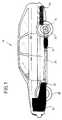
- eine Seitenansicht zur Darstellung der Einbauanlage;
- Fig. 2
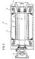
- einen Schnitt durch den Elektromotor.
- Fig. 1
- a side view showing the installation system;
- Fig. 2
- a section through the electric motor.
Mit dem Bezugszeichen 10 ist ein Hybridfahrzeug dargestellt, das im Bereich der Vorderräder 18 eine Brennkraftmaschine 16 sowie ein daran anschließendes Getriebe 12 aufweist. Am Getriebeausgang befindet sich ein Zwischendifferential, von dem zum einen eine Antriebswelle auf die Vorderräder 18 wirkt, sowie über eine Kardanwelle 20 und ein Hinterachsdifferential 14 die Hinterräder 22 angetrieben werden.
Zusätzlich ist ein Elektromotor 24 vorgesehen, der über einen Batteriesatz 26 mit elektrischer Energie versorgt wird und die Kardanwelle antreiben kann.In addition, an
Der Aufbau des Elektromotors ist in Fig. 2 im Detail dargestellt. Der Elektromotor besitzt einen Rotor oder Läufer 32 und einen Ständer oder Stator 34, der Stator 34 ist aus einzelnen Wicklungen mit entsprechenden Wikkelköpfen 36 gebildet.The structure of the electric motor is shown in detail in FIG. 2. The electric motor has a rotor or
Der Rotor 32 bildet dabei einen Teil der Kardanwelle 20 und ist durch einen Flansch 44 direkt mit ihr verbunden. Die Außenseite des Rotors 32 ist mit Permanentmagneten 38 beklebt. Zwischen den Permanentmagneten 38 mit Bandagen und dem Stator 34 ist ein Luftspalt 40 vorgesehen. Ein Gehäuse 42 umschließt den Aufbau.The
Im Bereich 46, dem Ende 44 mit der angeflanschten Kardanwelle 20 gegenüberliegend ist die direkte Verbindung des Elektromotors 24 mit dem Hinterachsdifferential 14 vorgesehen.In the
Durch die Auslegung des Elektromotors als Permanentmagnet-Synchronmotor ist eine Umdrehungszahl des Läufers 32 von bis zu 10 000 Umdrehungen pro Minute möglich, so daß auch bei schnellaufenden Fahrzeugen ein ständiges Mitlaufen des Motors 24 möglich ist, ohne daß der Motor beschädigt wird.By designing the electric motor as a permanent magnet synchronous motor, a number of revolutions of the
Claims (3)
- Four-wheel motor vehicle with an engine/gearbox unit (16,18) in the region of the front axle (12), a driven front axle (12), with a drive output via an inter axle differential, a cardan shaft (20) and a rear-axle differential (22) onto the rear wheels for achieving permanent four-wheel drive, and with an additional electric motor for driving the cardan shaft (20), characterised in that the electric motor (24) has two drive outputs, one of which runs via the cardan shaft (20) to the front wheels and the second of which runs via the rear-axle differential (22) to the rear wheels.
- Motor vehicle according to claim 1, characterised in that the electric motor (24) is a permanent-magnet synchronous motor, the rotor of which is constituted by a section of the cardan shaft equipped with permanent magnets and surrounded by the stator.
- Motor vehicle according to claim 2, characterised in that the electric motor is combined with the rear-axle differential to form a standardised unit.
Applications Claiming Priority (3)
| Application Number | Priority Date | Filing Date | Title |
|---|---|---|---|
| DE4115306 | 1991-05-10 | ||
| DE4115306ADE4115306A1 (en) | 1991-05-10 | 1991-05-10 | TWO-AXLE MOTOR VEHICLE |
| PCT/EP1992/000749WO1992020544A1 (en) | 1991-05-10 | 1992-04-03 | Four wheel drive hybrid vehicle |
Publications (2)
| Publication Number | Publication Date |
|---|---|
| EP0584090A1 EP0584090A1 (en) | 1994-03-02 |
| EP0584090B1true EP0584090B1 (en) | 1994-10-12 |
Family
ID=6431404
Family Applications (1)
| Application Number | Title | Priority Date | Filing Date |
|---|---|---|---|
| EP92908028AExpired - LifetimeEP0584090B1 (en) | 1991-05-10 | 1992-04-03 | Four wheel drive hybrid vehicle |
Country Status (6)
| Country | Link |
|---|---|
| EP (1) | EP0584090B1 (en) |
| JP (1) | JPH07505591A (en) |
| AT (1) | ATE112721T1 (en) |
| CA (1) | CA2109321A1 (en) |
| DE (2) | DE4115306A1 (en) |
| WO (1) | WO1992020544A1 (en) |
Cited By (3)
| Publication number | Priority date | Publication date | Assignee | Title |
|---|---|---|---|---|
| GB2438609A (en)* | 2006-04-07 | 2007-12-05 | Ford Global Tech Llc | Four wheel drive hybrid vehicle with motor in final drive housing |
| US7533754B2 (en) | 2006-02-22 | 2009-05-19 | Ford Global Technologies, Llc | Hybrid motor vehicle driveline |
| DE102005026874B4 (en)* | 2005-06-10 | 2017-05-11 | Volkswagen Ag | Device and method for driving a vehicle |
Families Citing this family (15)
| Publication number | Priority date | Publication date | Assignee | Title |
|---|---|---|---|---|
| GB2275309B (en) | 1993-02-22 | 1997-10-29 | Yang Tai Her | Differential coupling and compounding system |
| DE4320993C2 (en)* | 1993-06-24 | 1999-05-12 | Porsche Ag | Compact passenger car |
| FR2723553A1 (en)* | 1994-08-12 | 1996-02-16 | Villibord Maurice Marcel | Motor vehicle with internal combustion engine drive and electrical battery drive |
| US5908077A (en)* | 1995-01-30 | 1999-06-01 | Chrysler Corporation | Environmentally sensitive hybrid vehicle |
| DE19639904B4 (en)* | 1995-09-29 | 2004-11-11 | Fuji Jukogyo K.K. | Drive unit for a hybrid vehicle |
| JP3255012B2 (en)* | 1996-05-02 | 2002-02-12 | トヨタ自動車株式会社 | Hybrid car |
| JP3861321B2 (en) | 1996-05-02 | 2006-12-20 | トヨタ自動車株式会社 | Hybrid car |
| DE10049197B4 (en)* | 2000-10-05 | 2017-02-09 | Daimler Ag | hybrid vehicle |
| US7174978B2 (en) | 2002-03-29 | 2007-02-13 | Aisin Aw Co., Ltd. | Hybrid drive unit, and front-engine/rear-drive type automobile having the hybrid drive unit mounted thereon |
| US20050205313A1 (en)* | 2004-03-19 | 2005-09-22 | Gilmore Curt D | Hybrid vehicle with power assisted prop shaft |
| JP5312400B2 (en)* | 2010-05-27 | 2013-10-09 | 日立建機株式会社 | Hybrid wheel loader |
| DE102011076530A1 (en)* | 2011-05-26 | 2012-11-29 | Zf Friedrichshafen Ag | Bearing arrangement of an electrical machine |
| US20130038179A1 (en)* | 2011-08-08 | 2013-02-14 | Honeywell International Inc. | Landing gear with integrated electric motor for electric taxi system |
| JP2014104967A (en)* | 2012-11-26 | 2014-06-09 | Nisshin Denki:Kk | Drive shaft utilizing power generating device |
| KR101701939B1 (en)* | 2015-08-17 | 2017-02-02 | 박태수 | Fuel saving driving assistance apparatus and method for vehicle |
Family Cites Families (6)
| Publication number | Priority date | Publication date | Assignee | Title |
|---|---|---|---|---|
| DE467381C (en)* | 1928-10-25 | Esslingen Maschf | Electric drive device for motor vehicles | |
| DE693234C (en)* | 1938-04-28 | 1940-07-05 | Henri Pieper | Power transmission arrangement for motorized vehicles, especially motor vehicles, with internal combustion engine and electric motor |
| US3904883A (en)* | 1973-06-22 | 1975-09-09 | Products Inc | Low or zero pollution hybrid energy converter and transmission unit |
| JPS6141834U (en)* | 1984-08-20 | 1986-03-17 | マツダ株式会社 | rotary piston engine |
| DE3522062C2 (en)* | 1985-06-20 | 1993-10-14 | Man Nutzfahrzeuge Ag | Hybrid vehicle |
| DE3940172A1 (en)* | 1989-12-05 | 1991-06-06 | Audi Ag | TWO AXLE VEHICLE |
- 1991
- 1991-05-10DEDE4115306Apatent/DE4115306A1/ennot_activeWithdrawn
- 1992
- 1992-04-03JPJP4507487Apatent/JPH07505591A/enactivePending
- 1992-04-03DEDE59200632Tpatent/DE59200632D1/ennot_activeExpired - Fee Related
- 1992-04-03ATAT92908028Tpatent/ATE112721T1/ennot_activeIP Right Cessation
- 1992-04-03WOPCT/EP1992/000749patent/WO1992020544A1/enactiveIP Right Grant
- 1992-04-03CACA002109321Apatent/CA2109321A1/ennot_activeAbandoned
- 1992-04-03EPEP92908028Apatent/EP0584090B1/ennot_activeExpired - Lifetime
Cited By (4)
| Publication number | Priority date | Publication date | Assignee | Title |
|---|---|---|---|---|
| DE102005026874B4 (en)* | 2005-06-10 | 2017-05-11 | Volkswagen Ag | Device and method for driving a vehicle |
| US7533754B2 (en) | 2006-02-22 | 2009-05-19 | Ford Global Technologies, Llc | Hybrid motor vehicle driveline |
| GB2438609A (en)* | 2006-04-07 | 2007-12-05 | Ford Global Tech Llc | Four wheel drive hybrid vehicle with motor in final drive housing |
| GB2438609B (en)* | 2006-04-07 | 2010-03-31 | Ford Global Tech Llc | Hybrid electric motor vehicles |
Also Published As
| Publication number | Publication date |
|---|---|
| DE59200632D1 (en) | 1994-11-17 |
| EP0584090A1 (en) | 1994-03-02 |
| ATE112721T1 (en) | 1994-10-15 |
| CA2109321A1 (en) | 1992-11-11 |
| JPH07505591A (en) | 1995-06-22 |
| DE4115306A1 (en) | 1992-11-12 |
| WO1992020544A1 (en) | 1992-11-26 |
Similar Documents
| Publication | Publication Date | Title |
|---|---|---|
| EP0584090B1 (en) | Four wheel drive hybrid vehicle | |
| EP1717090B1 (en) | All-wheel-drive motor vehicle | |
| DE4108647A1 (en) | Drive system for agricultural or industrial vehicle - uses electrical generator driving electric motor for each vehicle driven wheel | |
| DE102009056366A1 (en) | Drive system for a motor vehicle | |
| DE102020105843A1 (en) | Drive device for a motor vehicle | |
| DE3708193C2 (en) | ||
| DE102018123740A1 (en) | Hybrid transmission, hybrid drive arrangement and method for operating a hybrid drive arrangement | |
| WO2008142076A1 (en) | Hybrid drive for a motor vehicle | |
| DE102020123116A1 (en) | Drive unit and drive arrangement | |
| DE10222812A1 (en) | Electric steering drive system for a vehicle with wheel side steering | |
| DE4306381C2 (en) | Hybrid drive for a motor vehicle | |
| DE102006057857B4 (en) | Device and method for operating a motor vehicle with a plurality of drive units | |
| DE10120742A1 (en) | Wheel drive for vehicle has electric motor mounted between wheel axle and wheel rim flange and integrated into wheel rim, which forms at least part of magnetic short circuit for electric motor | |
| WO2023099442A1 (en) | Drive system for a vehicle, and vehicle comprising the drive system | |
| DE102009050956A1 (en) | Drive strand for hybrid vehicle, has two combustion engines and two electro-machines for optional drive of wheels of hybrid vehicle | |
| DE19919455C2 (en) | Hybrid drive for motor vehicles | |
| EP0077290B1 (en) | Longitudinal tandem drive unit for an electric rail vehicle | |
| DE102007019988A1 (en) | Allwheel-driven passenger car, has hybrid drive including electrical machine, and decoupler arranged between crankshaft of internal-combustion engine and electrical machine that is coupled with internal combustion engine | |
| EP2582539B1 (en) | Hybrid drive-train | |
| DE202022106631U1 (en) | Multi-speed dual motor drive unit | |
| DE102014215875A1 (en) | Drive device for a vehicle | |
| WO1995000351A1 (en) | Non-guided vehicle with two driving axles | |
| DE29800582U1 (en) | Drive unit for vehicles, especially for city buses | |
| DE102019208550A1 (en) | Rail vehicle drive train and rail vehicle | |
| DE102010020676A1 (en) | Motor vehicle has front axle and rear axle, which are propelled by drive, and electric machine, where rear axle is assigned to rear axle ratio gearbox that has gear ratio provided as front axle ratio gearbox |
Legal Events
| Date | Code | Title | Description |
|---|---|---|---|
| PUAI | Public reference made under article 153(3) epc to a published international application that has entered the european phase | Free format text:ORIGINAL CODE: 0009012 | |
| 17P | Request for examination filed | Effective date:19930625 | |
| AK | Designated contracting states | Kind code of ref document:A1 Designated state(s):AT CH DE FR GB LI | |
| 17Q | First examination report despatched | Effective date:19940307 | |
| GRAA | (expected) grant | Free format text:ORIGINAL CODE: 0009210 | |
| AK | Designated contracting states | Kind code of ref document:B1 Designated state(s):AT CH DE FR GB LI | |
| REF | Corresponds to: | Ref document number:112721 Country of ref document:AT Date of ref document:19941015 Kind code of ref document:T | |
| REF | Corresponds to: | Ref document number:59200632 Country of ref document:DE Date of ref document:19941117 | |
| GBT | Gb: translation of ep patent filed (gb section 77(6)(a)/1977) | Effective date:19941124 | |
| ET | Fr: translation filed | ||
| PLBE | No opposition filed within time limit | Free format text:ORIGINAL CODE: 0009261 | |
| 26N | No opposition filed | ||
| PGFP | Annual fee paid to national office [announced via postgrant information from national office to epo] | Ref country code:CH Payment date:19970605 Year of fee payment:6 | |
| PG25 | Lapsed in a contracting state [announced via postgrant information from national office to epo] | Ref country code:LI Free format text:LAPSE BECAUSE OF NON-PAYMENT OF DUE FEES Effective date:19980430 Ref country code:CH Free format text:LAPSE BECAUSE OF NON-PAYMENT OF DUE FEES Effective date:19980430 | |
| REG | Reference to a national code | Ref country code:CH Ref legal event code:PL | |
| PGFP | Annual fee paid to national office [announced via postgrant information from national office to epo] | Ref country code:DE Payment date:19990409 Year of fee payment:8 | |
| PGFP | Annual fee paid to national office [announced via postgrant information from national office to epo] | Ref country code:FR Payment date:19990419 Year of fee payment:8 | |
| PGFP | Annual fee paid to national office [announced via postgrant information from national office to epo] | Ref country code:AT Payment date:19990426 Year of fee payment:8 | |
| PGFP | Annual fee paid to national office [announced via postgrant information from national office to epo] | Ref country code:GB Payment date:20000323 Year of fee payment:9 | |
| PG25 | Lapsed in a contracting state [announced via postgrant information from national office to epo] | Ref country code:AT Free format text:LAPSE BECAUSE OF NON-PAYMENT OF DUE FEES Effective date:20000403 | |
| PG25 | Lapsed in a contracting state [announced via postgrant information from national office to epo] | Ref country code:FR Free format text:LAPSE BECAUSE OF NON-PAYMENT OF DUE FEES Effective date:20001229 | |
| PG25 | Lapsed in a contracting state [announced via postgrant information from national office to epo] | Ref country code:DE Free format text:LAPSE BECAUSE OF NON-PAYMENT OF DUE FEES Effective date:20010201 | |
| REG | Reference to a national code | Ref country code:FR Ref legal event code:ST | |
| PG25 | Lapsed in a contracting state [announced via postgrant information from national office to epo] | Ref country code:GB Free format text:LAPSE BECAUSE OF NON-PAYMENT OF DUE FEES Effective date:20010403 | |
| GBPC | Gb: european patent ceased through non-payment of renewal fee | Effective date:20010403 |