EP0583891B1 - Output method and apparatus - Google Patents
Output method and apparatusDownload PDFInfo
- Publication number
- EP0583891B1 EP0583891B1EP93305790AEP93305790AEP0583891B1EP 0583891 B1EP0583891 B1EP 0583891B1EP 93305790 AEP93305790 AEP 93305790AEP 93305790 AEP93305790 AEP 93305790AEP 0583891 B1EP0583891 B1EP 0583891B1
- Authority
- EP
- European Patent Office
- Prior art keywords
- data
- input data
- processing
- basis
- control language
- Prior art date
- Legal status (The legal status is an assumption and is not a legal conclusion. Google has not performed a legal analysis and makes no representation as to the accuracy of the status listed.)
- Expired - Lifetime
Links
Images


Classifications
- G—PHYSICS
- G06—COMPUTING OR CALCULATING; COUNTING
- G06K—GRAPHICAL DATA READING; PRESENTATION OF DATA; RECORD CARRIERS; HANDLING RECORD CARRIERS
- G06K15/00—Arrangements for producing a permanent visual presentation of the output data, e.g. computer output printers
- G—PHYSICS
- G06—COMPUTING OR CALCULATING; COUNTING
- G06K—GRAPHICAL DATA READING; PRESENTATION OF DATA; RECORD CARRIERS; HANDLING RECORD CARRIERS
- G06K2215/00—Arrangements for producing a permanent visual presentation of the output data
- G06K2215/0002—Handling the output data
- G06K2215/0005—Accepting output data; Preparing data for the controlling system
- G06K2215/0011—Accepting output data; Preparing data for the controlling system characterised by a particular command or data flow, e.g. Page Description Language, configuration commands
Definitions
- the present inventionrelates to a method of and apparatus for processing printer data, the data being in a control language or the like from, for example, a host computer or the like.
- the apparatusis set into an automatic switching allowable state such that when data is received and analyzed and processed, whether data which will be received next relates to which control language is judged and a processing mode can be switched to the process according to the control language.
- a method and apparatus describing such control language switchingis outlined in EP-A-0503902 (citable under Article 54(3) EPC only).
- the inventionis made in consideration of the above conventional apparatus and it is an object of the invention to provide output method and apparatus in which even when data to be received is stopped, data which is subsequently received can be accurately rapidly processed.
- the present inventionprovides a method of processing printer data comprising the steps of: receiving input data; discriminating the control language of the input data on the basis of said input data; processing the input data on the basis of the control language as discriminated by said discriminating step; wherein said processing step is carried out on the basis of the previously discriminated control language for input data newly received within a predetermined time after the previous data.
- the present inventionfurther provides processing apparatus for a printer, the apparatus comprising: means for receiving input data; means for discriminating the control language of the input data on the basis of said input data; means for processing the input data on the basis of the control language as discriminated by said discriminating means; wherein said processing means carries out processing on the basis of the control language previously discriminated, for input data newly received within a predetermined time after the previous data.
- Fig. 1is a block diagram showing a construction of a printer system according to an embodiment of the present invention.
- reference numeral 1denotes a host computer which generates print information comprising print data and a control code to a printer 2.
- reference numeral 21denotes an input buffer to store reception data
- 22denotes a CPU to control a printing apparatus
- 23denotes an ROM in which programs for a control code discriminating process for discriminating a control language which describes the received data and for, an analyzing process of the control language, and the like have been stored
- 24denotes a page buffer to store the received data every page
- 25denotes a bit map memory to store output image data of one page
- 26denotes a printer engine to output the image data stored in the bit map memory 25 to a recording paper
- 3denotes a printed output paper (or print sheet).
- An RAM 221is used as a work memory or the like of the CPU.
- a timer 222is used by the CPU 22.
- An operation panel 27is constructed by a keyboard and switches to directly give an instruction to the printer by the operator, a display panel, and the like.
- Fig. 2is a flowchart showing a procedure of a conventional output processing program stored in the ROM 23 and will be sequentially explained from step 1.
- the printing apparatusWhen no data is received, the printing apparatus is set in an automatic switching allowable state.
- the control language which describes the datais determined in accordance with the data content and a special analysing control language is set in an automatic switching allowable state in accordance with the result of the determination (step S2).
- the determination of the control languageis in response to an identifier of the control language associated with the data or the like.
- the control language which describes the datais determined and a state in which the control language which should be analyzed has been determined is called an analysis processing state.
- control commandsare read one by one from the input buffer (step S3).
- the commandis analyzed and processed (steps S4, S5, S6).
- the processing routineis returned to the automatic switching allowable state.
- the command read out from the input bufferis a command accompanied with a paper delivery process (step S5)
- output image datais formed in the bit map memory 25 (step S7).
- a printing processis performed and the processing routine is returned to the automatic switching allowable state (step S8).
- Fig. 3shows a state of the status transition according to the conventional method described above.
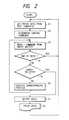
- Fig. 4is a flowchart showing a processing procedure by a program of the embodiment which is stored in the ROM 23. The processing procedure is executed by the CPU 22.
- step S41When data is received from the host computer 1 (step S41), a check is made to see if the operating mode is at present set to the automatic switching allowable state or not (step S42). A flag indicative of the automatic switching allowable state or the like has previously been stored in the RAM 221 and such a discrimination is made on the basis of the value of such a flag.
- step S42If YES in step S42, the rule which dominates the description of the reception data, namely, the data describing language is discriminated, the analyzing procedure suitable to the rule, i.e., describing language is determined, and the analysis processing state is started (step S43). The result is stored into the RAM 221. The data which is received after that is analyzed by the analyzing procedure based on the result which had been determined and was stored. After that, step S44 follows. When the operating mode has already been set into the analysis processing mode, the processing routine skips step S43 and directly advances to step S44.
- commandsare read out one by one from the input buffer (step S44).
- the end of datais judged (step S45).
- the presence or absence of a paper delivery processing instructionis checked (step S48).
- the read commandis processed (step S49).
- a time to subsequently maintain the analysis processing stateis set (step S46).
- the automatic switchingis inhibited (step S47).
- Such an inhibitioncan be realized by a method whereby a time is set into the timer 222 and when the time is over, the time-over is informed from the timer to the CPU by an interruption or the like.
- the time which is set into the timeris not limited to the timing at which no data exists in the input buffer 21 but can be also set to the timing when the reception of data from the host computer 1 is stopped.
- step S48When the command read out from the input buffer is a command accompanied with the paper delivery process in step S48, an outputting process is executed and the data in the bit map memory 25 is formed as a visible image on the recording paper (step S50).
- the processing routineis returned to the automatic switching allowable state (step S51).
- the image datais outputted to the print paper (step S52).
- Fig. 5shows an example of the method of the embodiment. That is, it is determined that the data which was received for the first time is described by the control language A, and the data is processed. Although the data reception is stopped at timing t 51 , since the procedure of the data has been received at timing t 52 before timing t 53 at which the analysis processing state which was set at that time is maintained, it is regarded that the data is described by the control language A, and the analyzing process is executed.
- a laser beam systemcan be also used as an image forming mechanism of the printer according to the embodiment.
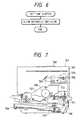
- Fig. 7is a cross sectional view showing an internal structure of a laser beam printer (hereinafter, abbreviated to an LBP) in this case.
- the LBPcan receive character pattern data or the like and can print the data onto a recording paper.
- reference numeral 740denotes an LBP main body to form an image onto a recording paper as a recording medium on the basis of the character pattern or the like which is supplied; 700 an operation panel on which switches for operations, an LBP display, and the like are arranged; and 701 a printer control unit to control the whole LBP 740 and to analyze the character pattern information or the like.
- the printer control unit 701mainly converts the character pattern information into the video signal and supplies to a laser driver 702.
- the laser driver 702is a circuit to drive a semiconductor laser 703 and on/off switches a laser beam 704 which is emitted from the semiconductor laser 703 in accordance with the inputted video signal.
- the laser beam 704is swung to the right and left by a rotary polygon mirror 705 and scans on an electrostatic drum 706.
- an electrostatic latent image of the character patternis formed on the drum 706.
- the latent imageis developed by a developing unit 707 arranged around the drum 706 and is copy transferred to the recording paper after that. Cut sheets are used as recording papers.
- the cut sheet recording papersare enclosed in a sheet cassette 708 set in the LBP main body 740 and are picked up and conveyed into the apparatus by a paper feed roller 709 and conveying rollers 710 and 711 and fed to the drum 706.
- the inventioncan be also applied to an ink jet printer, which will be explained hereinlater, or the like.
- Fig. 8is a schematic external view of an ink jet recording apparatus IJRA to which the invention can be applied.
- a lead screw 5005is rotated in association with the forward/reverse rotation of a driving motor 5013 through driving force transfer gears 5011 and 5009.
- a carriage HChas a pin (not shown) which is come into engagement with a spiral groove 5004 of the lead screw 5005.
- the carriage HCis reciprocated in the directions of arrows a and b.
- An ink jet cartridge IJCis mounted on the carriage HC.
- Reference numeral 5002denotes a paper pressing plate to press the paper onto a platen 5000 in the moving direction of the carriage; and 5007 and 5008 photocouplers serving as home position detecting means for detecting the presence of a lever 5006 of the carriage HC in a region of the photocouplers and for performing the switching of the rotating direction of the motor 5013 or the like.
- Reference numeral 5016denotes a member to support a capping member 5022 to cap the front surface of a recording head; and 5015 sucking means for sucking the air in the cap. The sucking means performs a sucking recovery of the recording head through an opening 5023 in the cap.
- Reference numeral 5017denotes a cleaning blade and 5019 a member for enabling the cleaning blade to be moved in the front/back direction.
- the cleaning blade 5017 and the member 5019are supported to a main body supporting plate 5018.
- the cleaning bladeis not limited to the shape shown in the diagram but a well-known cleaning blade can be also obviously applied.
- Reference numeral 5021denotes a lever to start the sucking operation in the sucking recovery.
- the lever 5021is moved in association with the movement of a cam 5020 which is come into engagement with the carriage.
- a driving force from the driving motoris transferred and controlled by well-known transfer means such as clutch switching or the like.
- a desired one of the processessuch as capping, cleaning, and sucking recovery can be executed at the corresponding positions by the operation of the lead screw 5005 when the carriage reach the region of the home position side.
- the embodimentcan be also applied to any apparatus so long as a desired operation is executed at a well-known timing.
- reference numeral 1700denotes an interface to input a recording signal; 1701 an MPU; 1702 a program ROM to store control programs which are executed by the MPU 1701; 1703 a dynamic RAM to preserve various kinds of data (the above recording signal, recording data which is supplied to the head, and the like); and 1704 a gate array to control the supply of the recording data to a recording head 1708.
- the gate arrayalso controls the data transfer among the interface 1700, the MPU 1701, and the RAM 1703.
- Reference numeral 1710denotes a carriage motor to convey the recording head 1708; 1709 a conveying motor to convey the recording paper; 1705 a head driver to drive the head; 1706 a motor driver to drive the conveying motor 1709; and 1707 a motor driver to drive the carriage motor 1710.
- the apparatushas a plurality of kinds of recording heads 1708 and head drivers 1705 in accordance with a resolution and need to be properly switched. Or, a dot diameter can be also changed by the head driver.
- the component elements of the inventioncan be assembled into the control construction of the ink jet printer as mentioned above.
- the inventionis not limited to the laser beam printer but can be also obviously applied to the above ink jet printer or the like.
- the printer sideis in a standby mode while expecting the input of the subsequent data for a predetermined period of time. Therefore, the data which is received later can be accurately processed.
- the processing timecan be reduced by eliminating the main switching operation.
- the time to maintain the analysis processing statehas been preset.
- a maintaining timecan be also set to an arbitrary time by a command from the host computer 1 or by an instruction which is inputted from the operation panel 27 by the operator.
- the time at which the signal transmission is stopped during the processing operationmay be measured and stored, and the time to maintain the analysis processing state may be automatically set to a proper value on the basis of the stored time.
- the inventioncan be applied to a system comprising a plurality of apparatuses or one apparatus.
- the inventioncan also be applied to the case where it is accomplished by suitable programming of a system.
- the printing method and apparatus according to the inventionhave the effect such that even when the data to be received is stopped during the processing operation, the data which is subsequently received can be accurately promptly processed.
Landscapes
- Engineering & Computer Science (AREA)
- General Engineering & Computer Science (AREA)
- Physics & Mathematics (AREA)
- General Physics & Mathematics (AREA)
- Theoretical Computer Science (AREA)
- Record Information Processing For Printing (AREA)
- Accessory Devices And Overall Control Thereof (AREA)
- Particle Formation And Scattering Control In Inkjet Printers (AREA)
- Controls And Circuits For Display Device (AREA)
Description
- The present invention relates to a method of andapparatus for processing printer data, the data being ina control language or the like from, for example, a hostcomputer or the like.
- In a conventional printing apparatus, the apparatusis set into an automatic switching allowable state suchthat when data is received and analyzed and processed,whether data which will be received next relates to whichcontrol language is judged and a processing mode can beswitched to the process according to the controllanguage. A method and apparatus describing such controllanguage switching is outlined in EP-A-0503902 (citableunder Article 54(3) EPC only).
- In the above conventional apparatus, however,there is a problem such that in the case where a longtime interval exists between the data while a seriesof data is received from a host computer as in thecase where an amount of data which is transmittedfrom the host computer is large or the like, theprinting apparatus determines that the data to bereceived ends, so that the processing mode isreturned to the automatic switching mode and the datasubsequent to the previously received data is not correctly analyzed but is abnormally outputted.On the other hand, since the switching operation isexecuted each time the reception of data is stopped,there is a case where a processing time becomes slow.
- The invention is made in consideration of theabove conventional apparatus and it is an object ofthe invention to provide output method and apparatusin which even when data to be received is stopped,data which is subsequently received can be accuratelyrapidly processed.
- The present invention provides a method ofprocessing printer data comprising the steps of:receiving input data; discriminating the control languageof the input data on the basis of said input data;processing the input data on the basis of the controllanguage as discriminated by said discriminating step;wherein said processing step is carried out on the basisof the previously discriminated control language forinput data newly received within a predetermined timeafter the previous data.
- The present invention further provides processingapparatus for a printer, the apparatus comprising: meansfor receiving input data; means for discriminating thecontrol language of the input data on the basis of saidinput data; means for processing the input data on the basis of the control language as discriminated by saiddiscriminating means; wherein said processing meanscarries out processing on the basis of the controllanguage previously discriminated, for input data newlyreceived within a predetermined time after the previousdata.
- Fig. 1 is a block diagram showing a fundamental construction according to an embodiment;
- Fig. 2 is a flowchart showing processingsof a conventional program;
- Fig. 3 is a diagram for explaining atransition of a state in a conventional printer;
- Fig. 4 is a flowchart showing processes ofa program according to the embodiment;
- Fig. 5 is a diagram for explaining atransition of a state in a printer of the embodiment;
- Fig. 6 is a flowchart showing processes of aprogram according to the embodiment;
- Fig. 7 is a cross sectional view of a laserbeam printer;
- Fig. 8 is a perspective view of an ink jetprinter;
- Fig. 9 is a block constructional diagram ofthe ink jet printer.
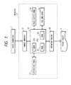
- Fig. 1 is a block diagram showing aconstruction of a printer system according to anembodiment of the present invention.
- In the diagram,
reference numeral 1 denotesa host computer which generates print informationcomprising print data and a control code to aprinter 2. - In the
printer 2, reference numeral 21denotes an input buffer to store reception data; 22 denotesa CPU to control a printing apparatus; 23 denotes an ROM inwhich programs for a control code discriminatingprocess for discriminating a control language whichdescribes the received data and for,an analyzing process of the controllanguage, and the like have been stored; 24 denotes a pagebuffer to store the received data every page; 25 denotes abit map memory to store output image data of onepage; 26 denotes a printer engine to output the image datastored in thebit map memory 25 to a recording paper;and 3 denotes a printed output paper (or print sheet). AnRAM 221 is used as a work memory or the like of theCPU. Atimer 222 is used by theCPU 22. Anoperation panel 27 is constructed by a keyboard andswitches to directly give an instruction to theprinter by the operator, a display panel, and the like. - Fig. 2 is a flowchart showing a procedure ofa conventional output processing program stored inthe
ROM 23 and will be sequentially explained fromstep 1. - When no data is received, the printingapparatus is set in an automatic switching allowablestate. When data is received from the host computer(step S1), the control language which describes thedata is determined in accordance with the data contentand a special analysing control language is set in anautomatic switching allowable state in accordancewith the result of the determination (step S2). In thiscase, the determinationof the control language is in response to an identifier of thecontrol language associated with the data or the like.Hereinafter, the control languagewhich describes the data is determined and a state inwhich the control language which should be analyzedhas been determined is called an analysis processingstate.
- After that, control commands are read one byone from the input buffer (step S3). The command isanalyzed and processed (steps S4, S5, S6). When nodata exists in the input buffer (step S4), theprocessing routine is returned to the automaticswitching allowable state. when the command read out from the input buffer is a command accompanied witha paper delivery process (step S5), output image datais formed in the bit map memory 25 (step S7). Aprinting process is performed and the processingroutine is returned to the automatic switchingallowable state (step S8).
- Fig. 3 shows a state of the status transitionaccording to the conventional method described above.
- That is, at timing t31, it is determined thatthe data which has been received for the first timefrom the automatic switching allowable stateindicates the control language A, so that the data isprocessed. At timing t32, the reception of the datais stopped (step S4 in Fig. 2), so that theprocessing routine is returned to the automaticswitching allowable state. When the subsequent datais received at timing t33, the control language whichdescribes the data is again decided. In thisinstance, however; it is judged such that the datahas been described by the control language B insteadof the control language A. Such an example is shownin Fig. 3. Therefore, since the data to beinherently processed as a control language A isprocessed as a control language B, the output resultis quite different from the result which wasinherently expected.
- A processing procedure according to theembodiment will now be described.
- Fig. 4 is a flowchart showing a processingprocedure by a program of the embodiment which isstored in the
ROM 23. The processing procedure isexecuted by theCPU 22. - When data is received from the host computer1 (step S41), a check is made to see if the operatingmode is at present set to the automatic switchingallowable state or not (step S42). A flag indicativeof the automatic switching allowable state or thelike has previously been stored in the
RAM 221 andsuch a discrimination is made on the basis of thevalue of such a flag. - If YES in step S42, the rule which dominatesthe description of the reception data, namely, thedata describing language is discriminated, theanalyzing procedure suitable to the rule, i.e.,describing language is determined, and the analysisprocessing state is started (step S43). The resultis stored into the
RAM 221. The data which isreceived after that is analyzed by the analyzingprocedure based on the result which had been determinedand was stored. After that, step S44 follows. Whenthe operating mode has already been set into theanalysis processing mode, the processing routine skips step S43 and directly advances to step S44. - Subsequently, commands are read out one byone from the input buffer (step S44). The end ofdata is judged (step S45). The presence or absenceof a paper delivery processing instruction is checked(step S48). The read command is processed (stepS49). When no data exists in the input buffer 21 instep S45, after the end of data, a time tosubsequently maintain the analysis processing stateis set (step S46). The automatic switching isinhibited (step S47). Such an inhibition can berealized by a method whereby a time is set into the
timer 222 and when the time is over, the time-overis informed from the timer to the CPU by aninterruption or the like. The time which is set intothe timer is not limited to the timing at which nodata exists in the input buffer 21 but can be alsoset to the timing when the reception of data from thehost computer 1 is stopped. - When the data is received from the hostcomputer in the analysis processing mode, it isregarded that the same data as that of the controllanguage which had been processed just before wasreceived, so that the analyzing process is executed.On the other hand, when the set time elapses, aninterruption signal or the like by the
timer 222 isused as a trigger and a processing procedure shown in a flowchart of Fig. 6 is executed. The automaticswitching state is started. - When the command read out from the inputbuffer is a command accompanied with the paperdelivery process in step S48, an outputting processis executed and the data in the
bit map memory 25 isformed as a visible image on the recording paper(step S50). The processing routine is returned tothe automatic switching allowable state (step S51).The image data is outputted to the print paper (stepS52). - Fig. 5 shows an example of the method of theembodiment. That is, it is determined that the datawhich was received for the first time is describedby the control language A, and the data is processed.Although the data reception is stopped at timing t51,since the procedure of the data has been receivedat timing t52 before timing t53 at which the analysisprocessing state which was set at that time ismaintained, it is regarded that the data is describedby the control language A, and the analyzing processis executed.
- A laser beam system can be also used as animage forming mechanism of the printer according tothe embodiment.
- Fig. 7 is a cross sectional view showing aninternal structure of a laser beam printer (hereinafter, abbreviated to an LBP) in this case.The LBP can receive character pattern data or thelike and can print the data onto a recording paper.
- In the diagram,
reference numeral 740 denotesan LBP main body to form an image onto a recordingpaper as a recording medium on the basis of thecharacter pattern or the like which is supplied; 700an operation panel on which switches for operations,an LBP display, and the like are arranged; and 701 aprinter control unit to control thewhole LBP 740and to analyze the character pattern information orthe like. Theprinter control unit 701 mainlyconverts the character pattern information into thevideo signal and supplies to alaser driver 702. - The
laser driver 702 is a circuit to driveasemiconductor laser 703 and on/off switches alaserbeam 704 which is emitted from thesemiconductorlaser 703 in accordance with the inputted videosignal. Thelaser beam 704 is swung to the right andleft by arotary polygon mirror 705 and scans on anelectrostatic drum 706. Thus, an electrostaticlatent image of the character pattern is formed onthedrum 706. The latent image is developed by adevelopingunit 707 arranged around thedrum 706 andis copy transferred to the recording paper afterthat. Cut sheets are used as recording papers. Thecut sheet recording papers are enclosed in asheet cassette 708 set in the LBPmain body 740 and arepicked up and conveyed into the apparatus by apaperfeed roller 709 and conveyingrollers drum 706. - As an image forming apparatus of theembodiment, the invention can be also applied to anink jet printer, which will be explained hereinlater,or the like.
- Fig. 8 is a schematic external view of an inkjet recording apparatus IJRA to which the inventioncan be applied. In the diagram, a
lead screw 5005 isrotated in association with the forward/reverserotation of a drivingmotor 5013 through drivingforce transfer gears 5011 and 5009. A carriage HChas a pin (not shown) which is come into engagementwith aspiral groove 5004 of thelead screw 5005.The carriage HC is reciprocated in the directions ofarrows a and b. An ink jet cartridge IJC is mountedon the carriage HC.Reference numeral 5002 denotesa paper pressing plate to press the paper onto aplaten 5000 in the moving direction of the carriage;and 5007 and 5008 photocouplers serving as homeposition detecting means for detecting the presenceof alever 5006 of the carriage HC in a region of thephotocouplers and for performing the switching of therotating direction of themotor 5013 or the like.Reference numeral 5016 denotes a member to support acapping member 5022 to cap the front surface of arecording head; and 5015 sucking means for suckingthe air in the cap. The sucking means performs asucking recovery of the recording head through anopening 5023 in the cap.Reference numeral 5017denotes a cleaning blade and 5019 a member forenabling the cleaning blade to be moved in thefront/back direction. Thecleaning blade 5017 andthemember 5019 are supported to a mainbodysupporting plate 5018. The cleaning blade is notlimited to the shape shown in the diagram but a well-knowncleaning blade can be also obviously applied.Reference numeral 5021 denotes a lever to start thesucking operation in the sucking recovery. Thelever 5021 is moved in association with the movement of acam 5020 which is come into engagement with thecarriage. A driving force from the driving motor istransferred and controlled by well-known transfermeans such as clutch switching or the like. - A desired one of the processes such ascapping, cleaning, and sucking recovery can beexecuted at the corresponding positions by theoperation of the
lead screw 5005 when the carriagereach the region of the home position side. Theembodiment can be also applied to any apparatus solong as a desired operation is executed at a well-known timing. - A control construction to execute therecording control of the above-mentioned apparatuswill now be described with reference to a blockdiagram shown in Fig. 9. In the diagram showing acontrol circuit,
reference numeral 1700 denotes aninterface to input a recording signal; 1701 an MPU;1702 a program ROM to store control programs whichare executed by theMPU 1701; 1703 a dynamic RAM topreserve various kinds of data (the above recordingsignal, recording data which is supplied to the head,and the like); and 1704 a gate array to control thesupply of the recording data to arecording head 1708. The gate array also controls the data transferamong theinterface 1700, theMPU 1701, and theRAM 1703.Reference numeral 1710 denotes a carriagemotor to convey therecording head 1708; 1709 aconveying motor to convey the recording paper; 1705 ahead driver to drive the head; 1706 a motor driverto drive the conveyingmotor 1709; and 1707 a motordriver to drive thecarriage motor 1710. - The operation of the above controlconstruction will now be described. When a recordingsignal is supplied to the
interface 1700, therecording signal is converted into the recording datafor printing between thegate array 1704 and theMPU 1701. Themotor drivers head driver 1705, therebyprinting. In case of the embodiment, the apparatushas a plurality of kinds ofrecording heads 1708 andhead drivers 1705 in accordance with a resolutionand need to be properly switched. Or, a dot diametercan be also changed by the head driver. - The component elements of the invention canbe assembled into the control construction of the inkjet printer as mentioned above. The invention is notlimited to the laser beam printer but can be alsoobviously applied to the above ink jet printer or thelike.
- As mentioned above, even in the case wherethe transmission of data is stopped during theprocessing operation when an amount of data to beprinted is large or the like, the printer side is ina standby mode while expecting the input of thesubsequent data for a predetermined period of time.Therefore, the data which is received later can beaccurately processed. The processing time can bereduced by eliminating the main switching operation.
- In the embodiment, the time to maintain theanalysis processing state has been preset. However,such a maintaining time can be also set to anarbitrary time by a command from the
host computer 1 or by an instruction which is inputted from theoperationpanel 27 by the operator. - When the
host computer 1 connected to theprinter 2 transmits a series of data, the time at which thesignal transmission is stopped during the processingoperation may be measured and stored, and the time tomaintain the analysis processing state may beautomatically set to a proper value on the basis of thestored time. - The invention can be applied to a system comprisinga plurality of apparatuses or one apparatus. Theinvention can also be applied to the case where it isaccomplished by suitable programming of a system.
- As described above, the printing method andapparatus according to the invention have the effect suchthat even when the data to be received is stopped duringthe processing operation, the data which is subsequentlyreceived can be accurately promptly processed.
Claims (8)
- A method of processing printer data comprising thesteps of:receiving input data;discriminating the control language of the inputdata on the basis of said input data;processing the input data on the basis of thecontrol language as discriminated by said discriminatingstep;wherein said processing step is carried out on thebasis of the previously discriminated control languagefor input data newly received within a predetermined timeafter the previous data.
- A method according to claim 1 wherein the step ofprocessing the input data includes a step of bufferingsaid input data and said predetermined time startsfrom the emptying of said buffer.
- A method according to claim 1 wherein saidpredetermined time starts from a time when datareception from a host is interrupted.
- A method according to any preceding claim furthercomprising the step of measuring the time at which saidinput data transmission is stopped and wherein said predetermined time is determined on the basis of said measurement.
- Processing apparatus for a printer, the apparatuscomprising:means (21) for receiving input data;means (22) for discriminating the control languageof the input data on the basis of said input data;means (22) for processing the input data on thebasis of the control language as discriminated by saiddiscriminating means;wherein said processing means carries out processingon the basis of the control language previouslydiscriminated, for input data newly received within apredetermined time after the previous data.
- Apparatus according to claim 5 wherein said means(21) for receiving input data includes data bufferingmeans and said predetermined time starts from theemptying of said buffer.
- Apparatus according to claim 5 wherein saidpredetermined time starts from a time when datareception from a host is interrupted.
- Apparatus according to any of claims 5 to 7 furthercomprising means (222) for measuring the time at whichsaid input data transmission is stopped, wherein said predetermined time is determined on the basis of saidmeasurement.
Applications Claiming Priority (3)
| Application Number | Priority Date | Filing Date | Title |
|---|---|---|---|
| JP19676092 | 1992-07-23 | ||
| JP4196760AJP2871960B2 (en) | 1992-07-23 | 1992-07-23 | Printing method and apparatus |
| JP196760/92 | 1992-07-23 |
Publications (3)
| Publication Number | Publication Date |
|---|---|
| EP0583891A2 EP0583891A2 (en) | 1994-02-23 |
| EP0583891A3 EP0583891A3 (en) | 1994-04-13 |
| EP0583891B1true EP0583891B1 (en) | 1999-10-13 |
Family
ID=16363170
Family Applications (1)
| Application Number | Title | Priority Date | Filing Date |
|---|---|---|---|
| EP93305790AExpired - LifetimeEP0583891B1 (en) | 1992-07-23 | 1993-07-22 | Output method and apparatus |
Country Status (6)
| Country | Link |
|---|---|
| US (2) | US6559957B1 (en) |
| EP (1) | EP0583891B1 (en) |
| JP (1) | JP2871960B2 (en) |
| KR (1) | KR940006060A (en) |
| CN (1) | CN1066274C (en) |
| DE (1) | DE69326725T2 (en) |
Families Citing this family (9)
| Publication number | Priority date | Publication date | Assignee | Title |
|---|---|---|---|---|
| KR960002074A (en)* | 1994-06-29 | 1996-01-26 | 김주용 | Printer input buffer and data input method using PIPO |
| JPH08195878A (en) | 1995-01-18 | 1996-07-30 | Canon Inc | Image processing device |
| CN1105991C (en)* | 1996-07-25 | 2003-04-16 | 明碁电脑股份有限公司 | Image output device |
| US7126703B1 (en)* | 1998-08-04 | 2006-10-24 | Sharp Laboratories Of America, Inc. | Printer controller with error recovery for multiple language capability |
| EP1253548A1 (en)* | 2001-04-26 | 2002-10-30 | Hewlett-Packard Company, A Delaware Corporation | Multi resolution printing |
| JP4401662B2 (en)* | 2002-03-29 | 2010-01-20 | キヤノン株式会社 | Print control apparatus and print control method |
| JP2005167882A (en)* | 2003-12-05 | 2005-06-23 | Ricoh Co Ltd | Remote management system |
| JP6088263B2 (en) | 2013-01-28 | 2017-03-01 | 東レエンジニアリング株式会社 | Inkjet coating device |
| CN110641178A (en)* | 2019-10-30 | 2020-01-03 | 上海商米科技集团股份有限公司 | Thermal printer and printing method thereof |
Family Cites Families (25)
| Publication number | Priority date | Publication date | Assignee | Title |
|---|---|---|---|---|
| US4633274A (en)* | 1984-03-30 | 1986-12-30 | Canon Kabushiki Kaisha | Liquid ejection recording apparatus |
| US5140675A (en)* | 1987-10-30 | 1992-08-18 | Canon Kabushiki Kaisha | Printer controller apparatus interfacing with external data sources |
| KR930009742B1 (en)* | 1988-03-17 | 1993-10-09 | 세이꼬 엡슨 가부시끼가이샤 | Printer |
| JPH01295854A (en)* | 1988-05-25 | 1989-11-29 | Canon Inc | printing device |
| JPH0786816B2 (en)* | 1988-08-23 | 1995-09-20 | セイコー電子工業株式会社 | Image recorder |
| US5045869A (en)* | 1988-09-16 | 1991-09-03 | Canon Kabushiki Kaisha | Printing controller for printing at selected resolutions |
| US5075874A (en)* | 1989-04-10 | 1991-12-24 | Eastman Kodak Company | Communications interface for computer output printer |
| JPH03110596A (en)* | 1989-09-26 | 1991-05-10 | Canon Inc | printing device |
| ES2101718T3 (en)* | 1990-03-02 | 1997-07-16 | Canon Kk | APPARATUS FOR IMAGE PROCESSING. |
| JPH045742A (en) | 1990-04-24 | 1992-01-09 | Canon Inc | Centro-connection device |
| JP2803322B2 (en) | 1990-05-01 | 1998-09-24 | ミノルタ株式会社 | Printer control device |
| US5303336A (en)* | 1990-05-14 | 1994-04-12 | Hitachi, Ltd. | Printing system including print server |
| JP2774369B2 (en)* | 1990-09-03 | 1998-07-09 | キヤノン株式会社 | Image recording device |
| US5165014A (en)* | 1990-09-12 | 1992-11-17 | Hewlett-Packard Company | Method and system for matching the software command language of a computer with the printer language of a printer |
| JPH04148430A (en) | 1990-10-12 | 1992-05-21 | Fujitsu Ltd | Timeout control method in emulator |
| JP3081233B2 (en) | 1990-11-22 | 2000-08-28 | 株式会社リコー | Image forming device |
| JP2861404B2 (en)* | 1991-01-10 | 1999-02-24 | ブラザー工業株式会社 | Printing device |
| JP3012344B2 (en) | 1991-01-11 | 2000-02-21 | キヤノン株式会社 | Printing equipment |
| EP0503902B1 (en)* | 1991-03-12 | 1999-07-28 | Canon Kabushiki Kaisha | Output method and apparatus using the same |
| JP2698252B2 (en) | 1991-09-25 | 1998-01-19 | 三田工業株式会社 | Printer |
| US5668936A (en) | 1991-09-25 | 1997-09-16 | Mita Industrial Co., Ltd. | Printer for exclusively selecting a host apparatus and a command system for use with the selected host apparatus |
| US20030156129A1 (en) | 1991-12-25 | 2003-08-21 | Tsutomu Takahashi | Information processing method and apparatus |
| JPH05169736A (en) | 1991-12-25 | 1993-07-09 | Canon Inc | Printer and printer control method |
| JPH05338329A (en) | 1992-06-05 | 1993-12-21 | Nec Corp | Language system changeover method of printer device |
| US5301037A (en)* | 1992-11-25 | 1994-04-05 | Xerox Corporation | Resolution conversion with simulated multi-bit gray |
- 1992
- 1992-07-23JPJP4196760Apatent/JP2871960B2/ennot_activeExpired - Fee Related
- 1993
- 1993-07-22EPEP93305790Apatent/EP0583891B1/ennot_activeExpired - Lifetime
- 1993-07-22KRKR1019930013881Apatent/KR940006060A/ennot_activeCeased
- 1993-07-22DEDE69326725Tpatent/DE69326725T2/ennot_activeExpired - Lifetime
- 1993-07-23CNCN93109070Apatent/CN1066274C/ennot_activeExpired - Lifetime
- 1996
- 1996-07-29USUS08/688,225patent/US6559957B1/ennot_activeExpired - Fee Related
- 1997
- 1997-07-16USUS08/895,551patent/US5852709A/ennot_activeExpired - Lifetime
Also Published As
| Publication number | Publication date |
|---|---|
| EP0583891A2 (en) | 1994-02-23 |
| JP2871960B2 (en) | 1999-03-17 |
| DE69326725D1 (en) | 1999-11-18 |
| KR940006060A (en) | 1994-03-23 |
| EP0583891A3 (en) | 1994-04-13 |
| US5852709A (en) | 1998-12-22 |
| DE69326725T2 (en) | 2000-04-27 |
| CN1081775A (en) | 1994-02-09 |
| JPH0640124A (en) | 1994-02-15 |
| CN1066274C (en) | 2001-05-23 |
| US6559957B1 (en) | 2003-05-06 |
Similar Documents
| Publication | Publication Date | Title |
|---|---|---|
| EP0834828B1 (en) | Hybrid printer equipped with a plurality of printing mechanisms and method of controlling it | |
| EP0862109B1 (en) | Information output apparatus and method | |
| US6219148B1 (en) | Printer spooler output apparatus and method with computer program and memory storage medium | |
| EP0583891B1 (en) | Output method and apparatus | |
| EP0564159A2 (en) | Output apparatus and method | |
| EP0902357B1 (en) | Output method and apparatus | |
| EP0651317B1 (en) | Output method and apparatus for estimating image quality prior to output | |
| US6567183B1 (en) | Output apparatus and output method | |
| US5889930A (en) | Output method and apparatus | |
| US5899614A (en) | Output method and apparatus | |
| US5768485A (en) | Printing apparatus for bit map data in unit of page | |
| EP0534723B1 (en) | Printing apparatus and method for storing various printing parameters | |
| US6397265B1 (en) | Print control apparatus for communicating with a selected external apparatus to control a printer | |
| JP2871981B2 (en) | Printing apparatus and control method thereof | |
| JPH1049314A (en) | Printer system and printer control method | |
| JP3281465B2 (en) | PRINTING APPARATUS, ITS CONTROL METHOD, AND ITS STATUS DISPLAY METHOD | |
| JPH06320796A (en) | Method and apparatus for image processing | |
| JPH07125326A (en) | Printing device and printing control method | |
| JPH064241A (en) | Method and device for printing | |
| JPH0732669A (en) | Printer | |
| JPH06198983A (en) | Printing device and method thereof | |
| JPH0624053A (en) | Printer | |
| JPH05284186A (en) | Printing device | |
| JPH079731A (en) | Printer |
Legal Events
| Date | Code | Title | Description |
|---|---|---|---|
| PUAI | Public reference made under article 153(3) epc to a published international application that has entered the european phase | Free format text:ORIGINAL CODE: 0009012 | |
| PUAL | Search report despatched | Free format text:ORIGINAL CODE: 0009013 | |
| AK | Designated contracting states | Kind code of ref document:A2 Designated state(s):DE FR GB IT | |
| AK | Designated contracting states | Kind code of ref document:A3 Designated state(s):DE FR GB IT | |
| 17P | Request for examination filed | Effective date:19940829 | |
| 17Q | First examination report despatched | Effective date:19970312 | |
| GRAG | Despatch of communication of intention to grant | Free format text:ORIGINAL CODE: EPIDOS AGRA | |
| GRAG | Despatch of communication of intention to grant | Free format text:ORIGINAL CODE: EPIDOS AGRA | |
| GRAG | Despatch of communication of intention to grant | Free format text:ORIGINAL CODE: EPIDOS AGRA | |
| GRAH | Despatch of communication of intention to grant a patent | Free format text:ORIGINAL CODE: EPIDOS IGRA | |
| GRAH | Despatch of communication of intention to grant a patent | Free format text:ORIGINAL CODE: EPIDOS IGRA | |
| GRAA | (expected) grant | Free format text:ORIGINAL CODE: 0009210 | |
| AK | Designated contracting states | Kind code of ref document:B1 Designated state(s):DE FR GB IT | |
| REF | Corresponds to: | Ref document number:69326725 Country of ref document:DE Date of ref document:19991118 | |
| ET | Fr: translation filed | ||
| ITF | It: translation for a ep patent filed | ||
| PLBE | No opposition filed within time limit | Free format text:ORIGINAL CODE: 0009261 | |
| STAA | Information on the status of an ep patent application or granted ep patent | Free format text:STATUS: NO OPPOSITION FILED WITHIN TIME LIMIT | |
| 26N | No opposition filed | ||
| REG | Reference to a national code | Ref country code:GB Ref legal event code:IF02 | |
| PGFP | Annual fee paid to national office [announced via postgrant information from national office to epo] | Ref country code:FR Payment date:20090722 Year of fee payment:17 | |
| REG | Reference to a national code | Ref country code:FR Ref legal event code:ST Effective date:20110331 | |
| PG25 | Lapsed in a contracting state [announced via postgrant information from national office to epo] | Ref country code:FR Free format text:LAPSE BECAUSE OF NON-PAYMENT OF DUE FEES Effective date:20100802 | |
| PGFP | Annual fee paid to national office [announced via postgrant information from national office to epo] | Ref country code:GB Payment date:20120730 Year of fee payment:20 | |
| PGFP | Annual fee paid to national office [announced via postgrant information from national office to epo] | Ref country code:IT Payment date:20120711 Year of fee payment:20 Ref country code:DE Payment date:20120731 Year of fee payment:20 | |
| REG | Reference to a national code | Ref country code:DE Ref legal event code:R071 Ref document number:69326725 Country of ref document:DE | |
| REG | Reference to a national code | Ref country code:GB Ref legal event code:PE20 Expiry date:20130721 | |
| PG25 | Lapsed in a contracting state [announced via postgrant information from national office to epo] | Ref country code:DE Free format text:LAPSE BECAUSE OF EXPIRATION OF PROTECTION Effective date:20130723 | |
| PG25 | Lapsed in a contracting state [announced via postgrant information from national office to epo] | Ref country code:GB Free format text:LAPSE BECAUSE OF EXPIRATION OF PROTECTION Effective date:20130721 |