EP0583829B1 - Method of realizing a prosthetic tooth for an implant and combination of elements used thereby - Google Patents
Method of realizing a prosthetic tooth for an implant and combination of elements used therebyDownload PDFInfo
- Publication number
- EP0583829B1 EP0583829B1EP93202371AEP93202371AEP0583829B1EP 0583829 B1EP0583829 B1EP 0583829B1EP 93202371 AEP93202371 AEP 93202371AEP 93202371 AEP93202371 AEP 93202371AEP 0583829 B1EP0583829 B1EP 0583829B1
- Authority
- EP
- European Patent Office
- Prior art keywords
- extension piece
- combination according
- screw thread
- tooth
- implant
- Prior art date
- Legal status (The legal status is an assumption and is not a legal conclusion. Google has not performed a legal analysis and makes no representation as to the accuracy of the status listed.)
- Expired - Lifetime
Links
Images

Classifications
- A—HUMAN NECESSITIES
- A61—MEDICAL OR VETERINARY SCIENCE; HYGIENE
- A61C—DENTISTRY; APPARATUS OR METHODS FOR ORAL OR DENTAL HYGIENE
- A61C8/00—Means to be fixed to the jaw-bone for consolidating natural teeth or for fixing dental prostheses thereon; Dental implants; Implanting tools
- A61C8/0048—Connecting the upper structure to the implant, e.g. bridging bars
- A61C8/005—Connecting devices for joining an upper structure with an implant member, e.g. spacers
- A61C8/0066—Connecting devices for joining an upper structure with an implant member, e.g. spacers with positioning means
- A—HUMAN NECESSITIES
- A61—MEDICAL OR VETERINARY SCIENCE; HYGIENE
- A61C—DENTISTRY; APPARATUS OR METHODS FOR ORAL OR DENTAL HYGIENE
- A61C8/00—Means to be fixed to the jaw-bone for consolidating natural teeth or for fixing dental prostheses thereon; Dental implants; Implanting tools
- A61C8/0048—Connecting the upper structure to the implant, e.g. bridging bars
- A61C8/005—Connecting devices for joining an upper structure with an implant member, e.g. spacers
- A61C8/0053—Connecting devices for joining an upper structure with an implant member, e.g. spacers with angular adjustment means, e.g. ball and socket joint
- A—HUMAN NECESSITIES
- A61—MEDICAL OR VETERINARY SCIENCE; HYGIENE
- A61C—DENTISTRY; APPARATUS OR METHODS FOR ORAL OR DENTAL HYGIENE
- A61C8/00—Means to be fixed to the jaw-bone for consolidating natural teeth or for fixing dental prostheses thereon; Dental implants; Implanting tools
- A61C8/0048—Connecting the upper structure to the implant, e.g. bridging bars
- A61C8/005—Connecting devices for joining an upper structure with an implant member, e.g. spacers
- A61C8/006—Connecting devices for joining an upper structure with an implant member, e.g. spacers with polygonal positional means, e.g. hexagonal or octagonal
Definitions
- This inventionrelates to a combination of elements for realizing a prosthetic tooth and to a method for manufacturing such combination of elements.
- the known methods for fixedly connecting dentures to a toothless jawcan, among other things, exist in implanting, after opening the mucosa or mucous membrane, of a cylindrical structure from a bio-compatible material, for instance titanium, in the bone of the upper or lower jaw, whereby this cylinder-shaped structure is completely countersunk in the bone, after which the mucosa or mucous membrane is sewn up and a waiting period of approximately six months is respected, in order to allow the bone to grow together, osseo-integrate respectively, with the implanted structure.
- a bio-compatible materialfor instance titanium
- the mucosa or mucous membraneis re-opened at the implant, and a temporary extension piece is screwed in the implant, after which the mucous membrane is sewn up again around this temporary extension piece.
- Such temporary extension pieceis used for obtaining, during the healing process of the mucous membrane, a correct transmucosal diameter.
- said temporary extension pieceis replaced with a definitive extension piece with the required length.
- Both the temporary and the definitive extension piecesare screwed in along the axis of the implant.
- Said definitive extension pieceis provided occlusally with internal screw-thread upon which the proper dentures can be screwed in the direction of the axis of the implant.
- a bridge structurefor instance in the form of a tooth ring, to be screwed in.
- small holesare provided through which a prosthesis screw is applied for connecting the tooth ring to each implant.
- the above applied prosthesis screwsare usually screwed tight in the direction of the axis of the extension piece, so that the axis direction of the implant determines the axis direction of the extension piece and thus also the axis direction of the tooth placed thereupon with the prosthesis screw.
- the bone quality, the bone volume and the anatomic limitations of the lower and especially upper jawsometimes force the surgeon to place the implant at a location not corresponding to the natural location of the former tooth position, thus causing afterwards functional, hygienic and aesthetic complications in the prosthetic field.
- pre-formed and inclined extension piecesare known, which are glued in the implant, having as a disadvantage, however, that a permanent connection is obtained.
- bendable extension pieces with a thin neckare known, which can be screwed in the implant; however, they turn out to break easily.
- deformable or grindable synthetic extension pieceswhich are cast in metal through a lost wax casting technique, so that an individual extension piece is obtained, which is breakable, however, and usually fits badly in the implant. Moreover, this method is time-consuming and the extension pieces are not reproduceable if a replacement is necessary.
- extension piecesare provided with a ball joint which can be locked. These extension pieces present the disadvantage that they are very complex and very breakable due to their small dimensions.
- the present inventionaims a solution which is advantageous in view of the abovementioned known techniques.
- the present inventionprovides in a combination of elements for realizing a prosthetic tooth for a dental implant, characterized in that this combination consists of, on the one hand, an orientation axle which can be screwed in an implant and which is provided with marks allowing to determine the required adjustment, and, on the other hand, a series of direction-adjusting extension pieces, which can be screwed in the implant after screwing out said orientation axle and which consecutively allow an axis adjustment corresponding to one of the marks on the orientation axle.
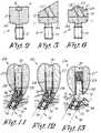
- an orientation axle 1as represented schematically in figure 1 which consists of, on the one hand, a screw thread part 2, and, on the other hand, of a cylindrical body 3 with flat occlusal end 4 on which marks 5 are provided.
- these marks 5consist of radial stripes 6 applied to the flat occlusal wall 4 with a corresponding identification element 7, such as for instance numbers or letters, in this case the letters A to H.
- the flat top 4can be provided with a hole 8, for instance a hexagon, to facilitate the screwing in and out of the orientation axle.
- the marks 6can be continued on the circumference of the cylindrical body 3.
- the figures 3 and 4represent a schematic view of a first direction-adjusting extension piece 9 according to the invention, which is used with the method according to the invention.
- This extension piece 9consists of, on the one hand, a screw thread part 10 which is identical to the screw thread part 2 of the orientation axle 1, on which a head 11 is provided, and, on the other hand, of a proper direction-adjusting element 12 connected to this head 11, which is provided with a screw thread 13 directed aslant in relation to the axis of the extension piece 9.
- the direction-adjusting element 12is provided at its upper surface with a mark 14 which can correspond to one of the marks 5 of the orientation axle 1 and which is preferably provided in a similar manner with an indication, in this case the indication A, which implies that this extension piece corresponds to a correction mark A of the orientation axle 1.
- Figure 5represents a direction-adjusting extension piece, which merely differs from the extension piece in figure 4 in that its occlusal surface is directed aslant, more specifically at right angles to the heart line of the screw thread 13.
- Figure 6represents a direction-adjusting extension piece which will be discussed in further detail hereafter.
- the orientation axle 1can be realized automatically in one part.
- the screw thread part 2 provided at the apical end of the orientation axle 1is manufactured in such a way that it is in accordance with the inner screw thread of the implant with wich it is used.
- This orientation axle 1is screwed in a mother matrix, for instance a plate, up to a fixed stop formed by the apical surface of the body 3 of the orientation axle 1.
- the mother matrixis provided around the orientation axle screwed therein, with marks, for instance stripes, which can be similarily applied on the orientation axle, for instance by means of laser technique, etching, scratching or the like.
- orientation axle 1is screwed out of the mother matrix and can be used as such.
- the mother matrixis then used for manufacturing the direction-adjusting extension pieces.
- the screw thread part 10 of the head 11is screwed in the mother matrix, more specifically in the screw thread hole in which the orientation axle 1 was screwed, up to a fixed stop formed by the apical surface of said head 11.
- the proper direction-adjusting part 12is placed on top of the basic element 10 and orientated thereupon by placing the mark 14 of this part 12 opposite to one of the marks applied in the mother matrix, in this case A to H.
- the marksare standardized on the mother matrix and thus also with respect to the coils of the screw thread part 2 and 10 of the orientation axle 1 and the head 11 respectively.
- Both the head 11 and the actual direction-adjusting part 12 of the extension piece 9are manufactured automatically.
- these partsare permanently connected, for instance by means of glueing, soldering or a laser technique, to form the complete extension piece 9, after which this extension piece 9 is screwed out of the mother matrix.
- direction-adjusting extension pieceswill be formed, whose axis adjustment corresponds to one of said marks, in other words extension pieces A, B, C, D, E, F, G and H.
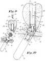
- Figures 7 and 8are schematic representations of a dental implant 15 which is applied in the bone 16 of the upper or lower jaw and which is already fully integrated therein.
- the bone 16is covered at the top with the mucosa or mucous membrane 18 which has been opened at the implant 15 so that the end 20 of the implant, provided with internal screw thread 19, can be reached via the mouth.
- an orientation axle 1is subsequently applied in the end 20 of the implant 15, as represented in figures 4 and 5.
- the screw thread parts 2 and 19 of the orientation piece 1 and the implant 15are similar to one another and can only be screwed together from a particular position until the apical surface of the cylindrical body 3 of the orientation axle 1 forms a stop against the occlusal surface of the implant 15. This causes the orientation axle 1 to be in one specific orientation.
- This orientation axle 1can be freely screwed in or out of the implant 15, or even be replaced with an other orientation axle 1, whose marks are also standardized.
- the dentistcan then decide which correction of the implantation axis 17 has to be executed and determine the corresponding direction-adjusting extension piece with the help of the marks 5 applied on the orientation axle 1.
- the dentistwill read a mark, for instance A, so that he knows that a corresponding direction-adjusting extension piece A will have to be placed.
- the orientation axle 1is screwed out of the implant and, as represented in figures 9 and 10, replaced by a direction-adjusting extension piece 9, which is screwed in the implant 15 with its screw thread part 10, until the apical part of the head 11 of this extension piece 9 forms a stop against the implant 15.
- the axis correctionis therefore automatically obtained since the aslant directed screw thread 13 is directed perpendicularly or almost perpendicularly to the bone 16.
- the actual direction-adjusting part 12is provided with a central part 21 in which for instance a transverse groove 22 is applied allowing for the extension piece 9 to be rotated by means of a fit tool, while around the central part 21 a cylindrical groove 23 is provided, a side edge of which is directed aslant.
- a supra-structure 24is connected by means of a prosthesis screw 25 which is screwed in the screw thread 13 of the extension piece 9, so that the axis 26 of the applied supra-structure 24 is identical to the direction previously determined, being the axis direction of the natural direction of the tooth 27.
- the supra-structure 24consists of a hollow support 28, whose apical extremity has a circumferential rib 29 with a slanting side edge, cooperating with the groove 23 in the extension piece 9 in order to position the hollow support 28 effectively with respect to the extension piece 9.
- the apical extremity of the hollow support 28has a slanting structure in this embodiment which can be connected to the extension piece 9.
- the actual tooth 27is maintained on the hollow structure 28, for instance by means of baked porcelain.
- the cavity 30will eventually be provided with a suitable filling 31.
- figure 11represents an embodiment of a supra-structure 24 which is meant to be used with a direction-adjusting extension piece 9 according to figure 4, whereas figure 12 represents an embodiment whereby the supra-structure 24 cooperates with a direction-adjusting extension piece 9 according to figure 5.
- figure 13represents a supra-structure 24 which will be used with a direction-adjusting extension piece 9 which is obtained and applied in the same way as described above, and whereby use is made of a conical axle 32 replacing the screw thread 13 and upon which the supra-structure 24 is maintained by clenching the conical hole 33 on the conical axle 32.
- both the orientation axle 1 and the direction correting extension pieces 9are preferably provided with a slanting edge 34 which facilitates the penetration of these parts 1 and 9 in the mucosa or mucous membrane.
Landscapes
- Health & Medical Sciences (AREA)
- Oral & Maxillofacial Surgery (AREA)
- Orthopedic Medicine & Surgery (AREA)
- Dentistry (AREA)
- Epidemiology (AREA)
- Life Sciences & Earth Sciences (AREA)
- Animal Behavior & Ethology (AREA)
- General Health & Medical Sciences (AREA)
- Public Health (AREA)
- Veterinary Medicine (AREA)
- Dental Prosthetics (AREA)
Description
Claims (18)
- Combination of elements for realizing a prosthetictooth for a dental implant, characterized in that thiscombination consists of, on the one hand, an orientationaxle (1) which can be screwed in an implant and which isprovided with marks (5) allowing to determine therequired adjustment, and, on the other hand, a series ofdirection-adjusting extension pieces (9), which can bescrewed in the implantafter screwing out said orientation axleand which consecutively allow anaxis adjustment corresponding to one of the marks (5) onthe orientation axle (1).
- Combination according to claim 1, characterized in thatthe orientation axle (1) consists of a screw thread part(2) and a body (3), being provided at least at its upperextension (4) with marks (5).
- Combination according to claim 2, characterized in thatits screw thread part (2) corresponds to the internalscrew thread (19) of an implant (15).
- Combination according to claim 2, characterized in thatthe marks (5) continue on the circumference of the body(3).
- Combination according to claim 2 or 4, characterized inthat each mark (5) is formed by a stripe (6).
- Combination according to claim 2, 4 or 5, characterizedin that with each mark an identification element (7) hasbeen applied, for instance the letters A, B, C, D, etc.
- Combination according to claim 1, characterized in thata direction-adjusting extension piece (9) mainlyconsists of a head (11) which is extended by a screwthread part (10) and the actual direction-adjusting part(12) connected to said head (11).
- Combination according to claim 1 or 7, characterized inthat in the actual direction-adjusting part (12) of theextension piece (9) a screw thread hole (13) isprovided, which is placed at an angle in relation to thelongitudinal direction of the extension piece (9).
- Combination according to claim 1 or 7, characterized inthat in the actual direction-adjusting part (12) of theextension piece (9) a screw thread hole (13) isprovided, which is placed at an angle in relation to thelongitudinal direction of the extension piece (9),whereby the occlusal wall of the actual direction-adjustingpart (12) is aslant and whereby this plane is directedat right angles to the screw thread hole (13).
- Combination according to claim 1 or 7, characterized inthat the occlusal wall of the actual direction-adjustingpart (12) is at right angles to the longitudinaldirection of the extension piece (9).
- Combination according to claim 1 or 7, characterized inthat the actual direction-adjusting part (12) of theextension piece (9) is formed by a conical axle (32)which is placed at an angle in relation to thelongitudinal direction of the extension piece.
- Combination according to claim 8, 9, 10 or 11,characterized in that the actual direction-adjustingpart (12) of the extension piece (9) is connected to thehead (11) thereof by means of glueing.
- Combination according to claim 8, 9, 10 or 11,characterized in that the actual direction-adjustingpart (12) of the extension piece (9) is connected to thehead (11) thereof by means of soldering or welding, forinstance laser welding.
- Combination according to claim 1 to 13, characterizedin that the tooth (27) which is to be connected to theextension piece (9), is mounted on a hollow support (28)in which, after mounting, a filling (31) can be applied,whereby this hollow support is executed aslant at itsapical end, whereby through the hollow support (28) a screw(25) can be applied for mounting the tooth (27) to theextension piece (9) by screwing it in the screw threadhole (13) thereof.
- Combination according to claim 1 to 13, characterizedin that the tooth (27) which is to be connected to theextension piece (9), is mounted on a hollow support (28)pin which, after mounting, a filling (31) can be applied,whereby this hollow support is executed at right anglesat its apical end, whereby through the hollow support (28) ascrew (25) can be applied for mounting the tooth (27)to the extension piece (9) by screwing it in the screwthread hole (13) thereof.
- Combination according to any one of claims 1 to 13,characterized in that the tooth (27) which is to beconnected to the extension piece (9), is mounted on ahollow support (28) in which at the occlusal end a filling (31) can be applied, whereby this hollow support is executedaslant at its apical end and is provided with a conical hole(33) fitting in a clenching way onto a conical axle (32)in order to connect the tooth (27) to the extensionpiece (9).
- Combination according to any one of claims 1 to 13,characterized in that the tooth (27) which is to beconnected to the extension piece (9), is mounted on aallow support (28) in which at the occlusal end a filling (31)can be applied, whereby this hollow support is executed atright angles at its apical end and is provided with aconical hole (33) fitting in a clenching way onto aconical axle (32) in order to connect the tooth (27) tothe extension piece (9).
- Method of manufacturing the combinationaccording to any one of claims 1 to 17,characterized in that they are realized by starting froman orientation axle (1) which is screwed completely in ascrew thread hole of a mother matrix; transferring marksprovided on this mother matrix to this orientation axle(1); screwing the thus formed orientation axle (1) out;screwing the head (11) of a direction-adjustingextension piece (9) completely in the same screw threadhole of the same mother matrix and connecting the actualdirection-adjusting part (12) of the extension piece (9)to said head (11), in such a way that a mark (14) ofthis part (12) is placed opposite to a correspondingmark of the mother matrix, all in such a way that foreach mark of the orientation axle (1) a differentextension piece (9) is obtained.
Applications Claiming Priority (2)
| Application Number | Priority Date | Filing Date | Title |
|---|---|---|---|
| BE9200726 | 1992-08-19 | ||
| BE9200726ABE1006129A3 (en) | 1992-08-19 | 1992-08-19 | Method for applying a richtingkorrigerend lens in a dentaalimplantaat elements and hereby apply. |
Publications (2)
| Publication Number | Publication Date |
|---|---|
| EP0583829A1 EP0583829A1 (en) | 1994-02-23 |
| EP0583829B1true EP0583829B1 (en) | 1998-12-16 |
Family
ID=3886400
Family Applications (1)
| Application Number | Title | Priority Date | Filing Date |
|---|---|---|---|
| EP93202371AExpired - LifetimeEP0583829B1 (en) | 1992-08-19 | 1993-08-13 | Method of realizing a prosthetic tooth for an implant and combination of elements used thereby |
Country Status (4)
| Country | Link |
|---|---|
| US (1) | US5350301A (en) |
| EP (1) | EP0583829B1 (en) |
| BE (1) | BE1006129A3 (en) |
| DE (1) | DE69322558T2 (en) |
Cited By (1)
| Publication number | Priority date | Publication date | Assignee | Title |
|---|---|---|---|---|
| US8353703B2 (en) | 1999-11-10 | 2013-01-15 | Biomet 3I, Llc | Healing components for use in taking impressions and methods for making the same |
Families Citing this family (25)
| Publication number | Priority date | Publication date | Assignee | Title |
|---|---|---|---|---|
| CA2132941C (en)* | 1994-09-26 | 1998-02-10 | Ernie Siegmund | Dental replacement mounting system |
| DE19509762A1 (en)* | 1995-03-17 | 1996-09-26 | Imz Fertigung Vertrieb | Endosseous single tooth implant with spacer sleeve |
| US5622499A (en)* | 1995-04-10 | 1997-04-22 | Simmons; William E. | Method of manufacturing a dental abutment |
| US5695334A (en)* | 1995-12-08 | 1997-12-09 | Blacklock; Gordon D. | Bendable and castable post and core |
| US5716215A (en)* | 1996-03-15 | 1998-02-10 | Blacklock; Gordon D. | Machinable post and core |
| SE510956C2 (en)* | 1997-11-11 | 1999-07-12 | Nobel Biocare Ab | Device for anchoring a threaded implant to bone, eg tooth bone, by means of a twisting tool |
| US5876204A (en)* | 1997-11-25 | 1999-03-02 | Sulzer Calcitek Inc. | Dental implant positioning guide |
| GB9924959D0 (en)* | 1999-10-21 | 1999-12-22 | Sethi Ashok | Implant alignment |
| US6406295B1 (en)* | 2001-07-13 | 2002-06-18 | Brian A. Mahler | Identification of dental implant components |
| US6997710B2 (en) | 2002-07-29 | 2006-02-14 | Americo Fernendes | Dental prosthesis post and core assembly |
| US6814577B2 (en) | 2002-10-09 | 2004-11-09 | Gordon D. Blacklock | Dental prosthesis abutment and waxing sleeve assembly |
| US7001392B2 (en)* | 2003-01-29 | 2006-02-21 | Howmedica Osteonics Corp. | Apparatus and method for preparing bone for antirotational implantation of an orthopedic endoprosthesis |
| ITFI20040013A1 (en)* | 2004-01-19 | 2004-04-19 | Leone Spa | DENTAL IMPLANT |
| SE528719C2 (en)* | 2005-06-03 | 2007-01-30 | Nobel Biocare Services Ag | Device for implants extending between a dental installation and the zygoma |
| JP5175291B2 (en)* | 2006-11-03 | 2013-04-03 | マテリアライズ・デンタル・ナムローゼ・フエンノートシャップ | Dental attachment assembly |
| BRPI0705570B8 (en) | 2007-05-24 | 2021-06-22 | Itp Inst De Tecnologia E Pesquisa Ltda | compensatory correction system for inclinations, converters and extenders and universal coupling abutments on osseointegrated implants |
| NL2002019C (en) | 2008-09-25 | 2010-03-29 | Biocomp Ind B V | IMPLANT CONSTRUCTION. |
| EP2494938A1 (en)* | 2011-03-03 | 2012-09-05 | Astra Tech AB | Dental implant assembly |
| US8944816B2 (en) | 2011-05-16 | 2015-02-03 | Biomet 3I, Llc | Temporary abutment with combination of scanning features and provisionalization features |
| WO2014081843A1 (en)* | 2012-11-20 | 2014-05-30 | Advanced Implant Intellectual Properties, Llc | Universal aligning adaptor system and methods |
| US9839496B2 (en) | 2013-02-19 | 2017-12-12 | Biomet 3I, Llc | Patient-specific dental prosthesis and gingival contouring developed by predictive modeling |
| ES2910276T3 (en)* | 2013-04-09 | 2022-05-12 | Biomet 3I Llc | Method of using scan data of a dental implant |
| USD734462S1 (en)* | 2013-08-20 | 2015-07-14 | Medical Corporation It | Guide member for a dental drill |
| EP3998040B1 (en) | 2013-12-20 | 2025-09-03 | Biomet 3i, LLC | Dental method for developing custom prostheses through scanning of coded members |
| US20230025033A1 (en)* | 2021-07-26 | 2023-01-26 | United States Of American As Represented By The Secretary Of The Navy | Dental implant identification system |
Family Cites Families (8)
| Publication number | Priority date | Publication date | Assignee | Title |
|---|---|---|---|---|
| US4187609A (en)* | 1975-03-17 | 1980-02-12 | Edelman Alfred E | Submerged functional implant and method |
| ATE47659T1 (en)* | 1981-08-14 | 1989-11-15 | O Hilt Tatum Jr | DENTAL IMPLANT. |
| US4734035A (en)* | 1986-04-09 | 1988-03-29 | Cheng Fat Hing | Endodontic stop positioner |
| US4854872B1 (en)* | 1987-09-24 | 1995-06-27 | Steven G Detsch | Prosthetic implant attachment system and method |
| US5018970A (en)* | 1987-12-17 | 1991-05-28 | Stordahl Finn R | Implant teeth--permanent bases with replaceable caps |
| US5030095A (en)* | 1989-08-16 | 1991-07-09 | Niznick Gerald A | Angled abutment for endosseous implants |
| US5092771A (en)* | 1990-11-21 | 1992-03-03 | Tatum Iii O Hilt | Rotary dental implant post |
| US5215460A (en)* | 1991-11-20 | 1993-06-01 | Perry William L | Method for paralleling implant restorative components |
- 1992
- 1992-08-19BEBE9200726Apatent/BE1006129A3/enactive
- 1993
- 1993-08-13DEDE69322558Tpatent/DE69322558T2/ennot_activeExpired - Fee Related
- 1993-08-13EPEP93202371Apatent/EP0583829B1/ennot_activeExpired - Lifetime
- 1993-08-19USUS08/108,796patent/US5350301A/ennot_activeExpired - Lifetime
Cited By (1)
| Publication number | Priority date | Publication date | Assignee | Title |
|---|---|---|---|---|
| US8353703B2 (en) | 1999-11-10 | 2013-01-15 | Biomet 3I, Llc | Healing components for use in taking impressions and methods for making the same |
Also Published As
| Publication number | Publication date |
|---|---|
| BE1006129A3 (en) | 1994-05-17 |
| DE69322558D1 (en) | 1999-01-28 |
| US5350301A (en) | 1994-09-27 |
| DE69322558T2 (en) | 1999-06-17 |
| EP0583829A1 (en) | 1994-02-23 |
Similar Documents
| Publication | Publication Date | Title |
|---|---|---|
| EP0583829B1 (en) | Method of realizing a prosthetic tooth for an implant and combination of elements used thereby | |
| EP0473262B1 (en) | Dental implant collar and post system | |
| US5759036A (en) | Complete dental implant system and method | |
| US6283752B1 (en) | Universal impression coping system | |
| US4854872A (en) | Prosthetic implant attachment system and method | |
| US5564921A (en) | Method of forming an abutment post | |
| US5015186A (en) | Dental implant attachment system | |
| US4988297A (en) | Alignment corrector for dental implants | |
| US5662473A (en) | Adjustable-angulation pattern for making a dental-implant abutment | |
| US4431416A (en) | Endosseous dental implant system for overdenture retention, crown and bridge support | |
| US5516288A (en) | Device and method for attaching a member in replacement of part of a set of teeth | |
| EP0787468B1 (en) | Impression coping | |
| US4187609A (en) | Submerged functional implant and method | |
| US6129548A (en) | Two-piece healing abutment system | |
| US5651675A (en) | Healing cap system | |
| EP0967931B1 (en) | Anatomical restoration dental implant system for posterior and anterior teeth | |
| JP3297435B2 (en) | Adjustable tooth implant system | |
| US5755574A (en) | Endosseous dental implant and method of manufacture | |
| US20030031981A1 (en) | Prosthetic implant | |
| KR20040023646A (en) | Implant for use in aesthetic regions of the mouth | |
| US20030044749A1 (en) | Stable dental analog systems | |
| US6250924B1 (en) | Dental implant system and a method for its manufacture | |
| EP0466267B1 (en) | Method for the realization of an implant prosthesis and parts hereby applied | |
| US5597303A (en) | Device and method for confirming bite registration for dental implants | |
| EP0525296B1 (en) | Osteointegrated assembly consisting of a pin and an interchangeable collar the height of which is selected according to the thickness of the patient's mucous epithelial connective tissue layer |
Legal Events
| Date | Code | Title | Description |
|---|---|---|---|
| PUAI | Public reference made under article 153(3) epc to a published international application that has entered the european phase | Free format text:ORIGINAL CODE: 0009012 | |
| AK | Designated contracting states | Kind code of ref document:A1 Designated state(s):DE FR IT | |
| 17P | Request for examination filed | Effective date:19940407 | |
| 17Q | First examination report despatched | Effective date:19960903 | |
| GRAG | Despatch of communication of intention to grant | Free format text:ORIGINAL CODE: EPIDOS AGRA | |
| GRAG | Despatch of communication of intention to grant | Free format text:ORIGINAL CODE: EPIDOS AGRA | |
| GRAH | Despatch of communication of intention to grant a patent | Free format text:ORIGINAL CODE: EPIDOS IGRA | |
| GRAH | Despatch of communication of intention to grant a patent | Free format text:ORIGINAL CODE: EPIDOS IGRA | |
| GRAA | (expected) grant | Free format text:ORIGINAL CODE: 0009210 | |
| AK | Designated contracting states | Kind code of ref document:B1 Designated state(s):DE FR IT | |
| REF | Corresponds to: | Ref document number:69322558 Country of ref document:DE Date of ref document:19990128 | |
| ITF | It: translation for a ep patent filed | ||
| ET | Fr: translation filed | ||
| PLBE | No opposition filed within time limit | Free format text:ORIGINAL CODE: 0009261 | |
| 26N | No opposition filed | ||
| REG | Reference to a national code | Ref country code:FR Ref legal event code:TP | |
| PGFP | Annual fee paid to national office [announced via postgrant information from national office to epo] | Ref country code:DE Payment date:20070803 Year of fee payment:15 | |
| PGFP | Annual fee paid to national office [announced via postgrant information from national office to epo] | Ref country code:IT Payment date:20070814 Year of fee payment:15 | |
| PGFP | Annual fee paid to national office [announced via postgrant information from national office to epo] | Ref country code:FR Payment date:20070806 Year of fee payment:15 | |
| REG | Reference to a national code | Ref country code:FR Ref legal event code:ST Effective date:20090430 | |
| PG25 | Lapsed in a contracting state [announced via postgrant information from national office to epo] | Ref country code:IT Free format text:LAPSE BECAUSE OF NON-PAYMENT OF DUE FEES Effective date:20080813 Ref country code:FR Free format text:LAPSE BECAUSE OF NON-PAYMENT OF DUE FEES Effective date:20080901 Ref country code:DE Free format text:LAPSE BECAUSE OF NON-PAYMENT OF DUE FEES Effective date:20090303 |