EP0583193B1 - Improvement to the assembly of a pump in a container - Google Patents
Improvement to the assembly of a pump in a containerDownload PDFInfo
- Publication number
- EP0583193B1 EP0583193B1EP93402002AEP93402002AEP0583193B1EP 0583193 B1EP0583193 B1EP 0583193B1EP 93402002 AEP93402002 AEP 93402002AEP 93402002 AEP93402002 AEP 93402002AEP 0583193 B1EP0583193 B1EP 0583193B1
- Authority
- EP
- European Patent Office
- Prior art keywords
- pump
- neck
- pump body
- length
- stopper
- Prior art date
- Legal status (The legal status is an assumption and is not a legal conclusion. Google has not performed a legal analysis and makes no representation as to the accuracy of the status listed.)
- Expired - Lifetime
Links
Images


Classifications
- B—PERFORMING OPERATIONS; TRANSPORTING
- B05—SPRAYING OR ATOMISING IN GENERAL; APPLYING FLUENT MATERIALS TO SURFACES, IN GENERAL
- B05B—SPRAYING APPARATUS; ATOMISING APPARATUS; NOZZLES
- B05B11/00—Single-unit hand-held apparatus in which flow of contents is produced by the muscular force of the operator at the moment of use
- B05B11/01—Single-unit hand-held apparatus in which flow of contents is produced by the muscular force of the operator at the moment of use characterised by the means producing the flow
- B05B11/10—Pump arrangements for transferring the contents from the container to a pump chamber by a sucking effect and forcing the contents out through the dispensing nozzle
- B05B11/1042—Components or details
- B05B11/1043—Sealing or attachment arrangements between pump and container
- B05B11/1046—Sealing or attachment arrangements between pump and container the pump chamber being arranged substantially coaxially to the neck of the container
- B05B11/1047—Sealing or attachment arrangements between pump and container the pump chamber being arranged substantially coaxially to the neck of the container the pump being preassembled as an independent unit before being mounted on the container
- B—PERFORMING OPERATIONS; TRANSPORTING
- B05—SPRAYING OR ATOMISING IN GENERAL; APPLYING FLUENT MATERIALS TO SURFACES, IN GENERAL
- B05B—SPRAYING APPARATUS; ATOMISING APPARATUS; NOZZLES
- B05B11/00—Single-unit hand-held apparatus in which flow of contents is produced by the muscular force of the operator at the moment of use
- B05B11/01—Single-unit hand-held apparatus in which flow of contents is produced by the muscular force of the operator at the moment of use characterised by the means producing the flow
- B05B11/10—Pump arrangements for transferring the contents from the container to a pump chamber by a sucking effect and forcing the contents out through the dispensing nozzle
- B05B11/1001—Piston pumps
- B05B11/1016—Piston pumps the outlet valve having a valve seat located downstream a movable valve element controlled by a pressure actuated controlling element
- B05B11/1018—Piston pumps the outlet valve having a valve seat located downstream a movable valve element controlled by a pressure actuated controlling element and the controlling element cooperating with means for opening or closing the inlet valve
Definitions
- the present inventionrelates to an improvement in the assembly of a pump in a tank.
- the pumps in questionare miniaturized pumps, generally actuated by a finger of a hand, for dispensing or spraying a fluid, liquid or pasty product such as a perfume, a cosmetic product, or a pharmaceutical product.
- Such a towergenerally has a substantially cylindrical side wall which surrounds the pump body in the vicinity of its second end, said side wall of the tower being extended radially outwards by a wheelbase which can be fixed on the neck of a container by wedging between a screw cap and said container neck.
- This mounting methodhas the disadvantage that a substantial part of the pump body protrudes above the neck of the container, which increases the size of the device.
- a screw capwhich has an internal axial through passage, said passage comprising a first substantially cylindrical section towards the outside of the container, and a second narrower section towards the inside of the container, said first and second sections defining a shoulder directed towards the outside of the container, the pump body being engaged in said second section and said collar being placed in abutment against the shoulder of the plug, and said pump body collar being held in said second section of the passage of the plug by an annular locking ring, force-fitted into a side wall cylindrical plug.
- this assemblyit is generally necessary to interpose a flat seal between the collar of the pump body and the locking ring.
- This method of attachmentis advantageous, since the pump body projects very slightly above the neck of the tank. However, it requires the use of a locking ring and an additional seal.
- the object of the present inventionis to propose a method of mounting a pump on a stopper or a container neck, which results in a space requirement which is as small as in a mounting with a locking ring, but which is simpler and less expensive than said mounting by locking ring.
- a pumpcan be fixed in the same way as described above, on the neck of a container, provided that the neck has the characteristics already described for the stopper.
- the neckis metallic, for example when the pump is fixed to a deformable aluminum tube, said neck is matted after assembly of the pump, to prevent any exit of said pump outside said neck.
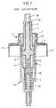
- FIG. 1represents a pump of the general type disclosed in documents FR-A-2,305,241 and FR-A-2,314,772, as well as in the US patent corresponds US-A-4,025,046.
- the pump presentedcomprises a body pump 1 with side wall cylindrical 1a which extends between a first end 1b and a second end 1c of the pump body.
- the first end 1bforms a bottom which comprises an inlet orifice 1d of the pump, while the second end 1c is open and has an external collar 12.
- Inside the pump bodyis mounted axially sliding a piston 2, secured to a push rod 3, which passes through the first end 1c of the pump body.
- the push rod 3is crossed axially by an outlet channel 3a, which has a narrowing 7a.
- valve 6which comprises a needle 7 engaged in the outlet channel 3a, and a skirt 8 which extends axially towards the first end 1b of the pump body.
- the pump bodyfurther comprises a tubular nozzle 4 which extends axially inside the side wall 1a, from the first end 1b.
- a spring 10biases the valve towards the second end 1c of the side wall l of the pump body, which tends to apply with sealing the needle 7 against the narrowing 7a of the outlet channel 3a, and to push the piston 2 towards the end 1c.
- a cylindrical ferrule 11is force fitted or snapped or otherwise fixed in the second end 1c, so as to limit the movement of the piston 2 towards said end 1c, thereby defining a rest position of the pump.
- the skirt 8When the pump is in the rest position, the skirt 8 is not engaged on the nozzle 4. When the rod 3 is pressed inside the pump body, the skirt 8 engages on the nozzle 4, thereby closing the inlet 1b. When the pressure prevailing inside the pump body is sufficient, the needle 7 comes off from the narrowing 7a, allowing the dose of substance included in the pump body to escape through the outlet channel 3a.
- the pumpis provided with a crimpable metal cup 13, which can be crimped on the one hand on the collar 12 and the ferrule 11, and on the other hand on the neck of a container. (not shown), conventionally.
- an annular flat seal 14 made of elastomeris interposed between the metal capsule 13 and the neck of a container.
- FIG. 2represents another fixing method known in the prior art.
- the pump represented in FIG. 2is similar to that of FIG. 1. It is adapted on a neck 18 of a container 19, by means of a cap 16 screwable onto said neck.
- the ferrule 11 of the pumpis extended externally by a spinner 15, comprising a first annular wall 15a, extending radially outward from the ferrule 11, as far as the neck 12 of the pump body, said first annular wall 15a being extended axially towards the neck of the container by a lateral annular wall 15b, up to a wheelbase 15c.
- the plug 16has an inner flange 16a, which comes to tighten the wheelbase 15c against the neck 18 of the container during assembly.
- a flat annular seal 14is disposed between the wheelbase 15c and the neck 18.
- FIG. 3it is also known to assemble a pump body 1 on a plug 20 screwable on the neck of a container, by providing in the plug 20 an axial internal passage 21 which passes through it, said axial passage 21 comprising a first cylindrical section 22, further from the container when the cap is screwed onto the neck of the container, and a second narrower section 23, closer to the container when the cap is screwed onto the container.
- the first section 22has a diameter substantially equal to the outside diameter of the collar 12 of the pump body.
- the internal passage 21defines a shoulder 24, directed towards the outside of the container.
- the collar 12 of the pump bodyis located inside the first section 22 of the interior passage 21, while the side wall 1a of the pump body is engaged inside the second section 23 of the interior passage 21 of the plug.
- the collar 12 and the ferrule 11 of the pumpare held in the first section 22 of the passage 21, by an annular locking ring 25.
- the plug 20has an annular wall 26, formed around the interior passage 21, and which extends axially away from the container.
- the annular locking ring 25is forcibly fitted inside the side wall 26, and said annular ring 25 has an axial central orifice 25a, of diameter less than the diameter of the first section 22 of the interior passage 21, so as to maintain the collar 12 of the pump body.
- An annular flat seal 27is arranged on the locking ring 25, so as to perfect the seal between the ring on the one hand, the pump body and the plug on the other hand.
- FIG. 4shows an embodiment of the fixing method according to the invention.
- the pump shown in FIG. 4is identical to that of the preceding figures, but the invention is not limited to this particular type of pump, the important thing being that the pump comprises a pump body provided at its upper end with an outer collar and a ferrule preventing the piston from exiting the pump under the effect of the internal return spring.
- the pump bodyis fixed to the neck of a container (not shown) by means of a plug 20.
- the plug 20has a skirt 20a provided with an internal thread, which allows the plug to be screwed onto the neck of the container. .
- the plug 20further comprises an internal annular flange 20b, which extends radially inwards from the skirt 20a, to a central orifice 22 which has a diameter substantially equal to or slightly greater than the external diameter of the wall lateral of the pump body, but less than the external diameter of the collar 12 of the pump body.
- a cylindrical side wall 28extends axially from the flange 20b, away from the container, said side wall 28 surrounding the orifice 22. The diameter inside of the side wall 28 is substantially equal to the outside diameter of the collar 12.
- the orifice 22 and the side wall 28define an axial internal passage which passes through the plug, said passage comprising a first section 23 delimited by the side wall 28 , and a second section 22 corresponding to the central orifice of the flange 20b. Between the sections 22 and 23 is defined a shoulder 24 directed towards the outside of the container.
- the plug 20further comprises a cylindrical wall 26, which extends axially away from the container substantially in the extension of the skirt 20a.
- the side wall 26has essentially an aesthetic purpose and a purpose of guiding a pusher mounted on the rod 3 of the pump.
- the ferrule 11comprises a radial crown 11a which has a diameter slightly greater than the inside diameter of the side wall 28.
- the radial crown 11ais force-fitted inside the side wall 28 and said crown 11a keeps the pump body fixed in the plug 20, by blocking the shoulder 12 inside the housing defined by the side wall 28 and the shoulder 24.
- the crown 11ahas a notch-shaped peripheral outer edge 11b, having a sliding chamfered surface 11c, closer to the container, and a stop surface 11d further from the container, and substantially perpendicular to the axis of revolution of the ferrule.
- the ferrule 11is made of a material harder than the side wall 28, so that the notch 11b can bite inside the side wall 28, making the assembly even more solid.
- the plug 20can be made of polypropylene, while the ferrule 11 is made of harder acetal resin.
- the pumpis of the type operating with air intake, that is to say that it returns air to the container on each actuation.
- the ferrule 11may have an axial groove 11f and the collar 12 may have an axial groove 12a, so as to communicate the interior of the container with the atmosphere during actuation of the pump, as it is well known in the state of the art.
- the method of attachment shown in Figure 4is also applicable to pumps operating without air intake, that is to say in the present case, pumps not having the grooves 11f and 12a.
- the container 39which can for example be a deformable tube adapted to flatten progressively under the effect of the suction of the pump, comprises a neck 30 provided with an inner annular flange 30b, which s 'extends radially inwards to a central orifice 33.
- the internal diameter of the central orifice 33is substantially equal to or slightly greater than the external diameter of the side wall 1a of the pump body.
- a cylindrical side wall 38extends axially towards the outside of the container from the flange 30b, surrounding the orifice 33.
- the cylindrical side wall 38has an inside diameter substantially equal to the outside diameter of the collar 12.
- the wall 38 and the orifice 33thus define an axial internal passage which passes through the neck 30, with a first section 32 inside the side wall 38, and a second section 33 corresponding to the central orifice of the flange 30b. Between the sections 32 and 33, a shoulder 34 is defined, directed towards the outside of the container.
- the pump bodyis fixed as in the example of FIG. 4 inside the side wall 38, by means of two superimposed radial rings 11a of the ferrule 11, which have an outside diameter slightly greater than the inside diameter of the side wall 38, and which are forced into said side wall 38.
- the container 39is a deformable tube, it can be made of plastic, or optionally of metal, for example aluminum.
- the shape of the neck 30will generally be simpler, the side wall 38 being generally thicker, and the neck 30 not having the second side wall 36.
- itcan it is advantageous to mat the free end of the side wall 38, so as to form an internal bead 38a which prevents any exit of the pump body from said side wall 38.
- the ring 11a of the ferrulemay not be force-fitted, but snapped inside the side wall 38, said side wall having an internal bead 38a which allows the snap-fastening.
- the side wall 38may optionally include one or more sealing beads 38b, which bear against the collar 12 of the pump body 1, when the pump is operating without air intake.
- the neck 12also has a notch shape, with a chamfered surface 12b close to the reservoir, the sealing bead 38b pressing against said chamfered surface 12b.
- FIG. 7represents a variant of FIG. 6 in which the collar 12 also has a notch shape with an external edge 12c in sealed contact with the side wall 38.
Landscapes
- Closures For Containers (AREA)
- Reciprocating Pumps (AREA)
- Containers And Packaging Bodies Having A Special Means To Remove Contents (AREA)
Description
Translated fromFrenchLa présente invention concerne un perfectionnement à l'assemblage d'une pompe dans un réservoir. Les pompes dont il s'agit sont des pompes miniaturisées, généralement actionnées par un doigt d'une main, pour distribuer ou pulvériser un produit fluide, liquide ou pâteux tel qu'un parfum, un produit cosmétique, ou un produit pharmaceutique.The present invention relates to an improvement in the assembly of a pump in a tank. The pumps in question are miniaturized pumps, generally actuated by a finger of a hand, for dispensing or spraying a fluid, liquid or pasty product such as a perfume, a cosmetic product, or a pharmaceutical product.
Particulièrement, l'invention concerne des pompes comportant :
- un corps de pompe ayant une paroi latérale s'étendant axialement entre une première extrémité qui comporte un orifice d'entrée et une deuxième extrémité ouverte dotée d'un collet externe,
- un piston qui coulisse axialement dans ladite paroi latérale, et un ressort de rappel qui sollicite le piston vers la deuxième extrémité du corps de pompe,
- une virole fixée dans la deuxième extrémité de la paroi latérale du corps de pompe, pour limiter le mouvement du piston vers ladite deuxième extrémité.
- a pump body having a side wall extending axially between a first end which has an inlet orifice and a second open end provided with an external collar,
- a piston which slides axially in said side wall, and a return spring which biases the piston towards the second end of the pump body,
- a ferrule fixed in the second end of the side wall of the pump body, to limit the movement of the piston towards said second end.
Il existe plusieurs façons bien connues pour fixer une telle pompe sur un col d'un récipient de ladite substance fluide à distribuer ou à pulvériser, ou sur un bouchon pouvant être fixé sur un tel col. Tout d'abord, il est possible de sertir la pompe sur le col du récipient au moyen d'une coupelle métallique. Ce mode de montage présente l'inconvénient d'être peu esthétique, et en outre, une partie du corps de pompe dépasse forcément au-dessus du col du récipient, ce qui tend à augmenter légérement l'encombrement de l'ensemble du dispositif distributeur de substance fluide.There are several well-known ways to fix such a pump on a neck of a container of said fluid substance to be dispensed or sprayed, or on a plug which can be fixed on such a neck. First of all, it is possible to crimp the pump on the neck of the container by means of a metal cup. This mounting method has the disadvantage of being unsightly, and in addition, a part of the pump body necessarily protrudes above the neck of the container, which tends to slightly increase the size of the entire dispensing device. of fluid substance.
Ensuite, il est possible d'utiliser une pièce généralement appelée tourette, qui est solidaire de la virole du corps de pompe. Une telle tourette présente généralement une paroi latérale sensiblement cylindrique, qui entoure le corps de pompe au voisinage de sa deuxième extrémité, ladite paroi latérale de la tourette étant prolongée radialement vers l'extérieur par un empattement qui peut être fixé sur le col d'un récipient par coincement entre un bouchon vissable et ledit col du récipient. Ce mode de montage présente l'inconvénient qu'une part substancielle du corps de pompe saille au-dessus du col du récipient, ce qui augmente l'encombrement du dispositif.Then, it is possible to use a part generally called a turret, which is integral with the shell of the pump body. Such a tower generally has a substantially cylindrical side wall which surrounds the pump body in the vicinity of its second end, said side wall of the tower being extended radially outwards by a wheelbase which can be fixed on the neck of a container by wedging between a screw cap and said container neck. This mounting method has the disadvantage that a substantial part of the pump body protrudes above the neck of the container, which increases the size of the device.
En outre, il est possible d'utiliser un bouchon vissable qui comporte un passage intérieur axial traversant, ledit passage comportant un premier tronçon sensiblement cylindrique vers l'extérieur du récipient, et un deuxième tronçon plus étroit vers l'intérieur du récipient, lesdits premier et deuxième tronçons définissant un épaulement dirigé vers l'extérieur du récipient, le corps de pompe étant engagé dans ledit deuxième tronçon et ledit collet étant placé en butée contre l'épaulement du bouchon, et ledit collet du corps de pompe étant maintenu dans ledit deuxième tronçon du passage du bouchon par une bague annulaire de verrouillage, emboîtée à force dans une paroi latérale cylindrique du bouchon. Dans cet assemblage, il est généralement nécessaire d'interposer un joint plat d'étanchéité entre le collet du corps de pompe et la bague de verrouillage. Ce mode de fixation est avantageux, dans la mesure où le corps de pompe saille très faiblement au-dessus du col du réservoir. Toutefois, il nécessite l'emploi d'une bague de verrouillage et d'un joint d'étanchéité supplémentaire.In addition, it is possible to use a screw cap which has an internal axial through passage, said passage comprising a first substantially cylindrical section towards the outside of the container, and a second narrower section towards the inside of the container, said first and second sections defining a shoulder directed towards the outside of the container, the pump body being engaged in said second section and said collar being placed in abutment against the shoulder of the plug, and said pump body collar being held in said second section of the passage of the plug by an annular locking ring, force-fitted into a side wall cylindrical plug. In this assembly, it is generally necessary to interpose a flat seal between the collar of the pump body and the locking ring. This method of attachment is advantageous, since the pump body projects very slightly above the neck of the tank. However, it requires the use of a locking ring and an additional seal.
La présente invention a pour but de proposer un mode de montage d'une pompe sur un bouchon ou un col de récipient, qui entraîne un encombrement aussi faible que dans un montage à bague de verrouillage, mais qui soit plus simple et moins coûteux que ledit montage par bague de verrouillage.The object of the present invention is to propose a method of mounting a pump on a stopper or a container neck, which results in a space requirement which is as small as in a mounting with a locking ring, but which is simpler and less expensive than said mounting by locking ring.
La présente invention a pour objet un dispositif distributeur de substance fluide comportant une pompe montée sur un bouchon destiné à être fixé sur un col d'un récipient de ladite substance fluide, dans lequel :
- la pompe comporte un corps de pompe s'étendant axialement entre une première extrémité qui comporte un orifice d'entrée et une deuxième extrémité ouverte dotée d'un collet externe, la pompe comporte en outre un piston qui coulisse axialement dans ledit corps de pompe et un ressort de rappel qui sollicite le piston vers la deuxième extrémité ouverte du corps de pompe, et la pompe comporte une virole formée d'une seule pièce fixée dans ladite deuxième extrémité du corps de pompe, pour limiter le mouvement du piston vers ladite deuxième extrémité,
- le bouchon comporte un passage intérieur axial qui le traverse, ledit passage comportant un premier tronçon sensiblement cylindrique vers l'extérieur du récipient et un deuxième tronçon plus étroit vers l'intérieur du récipient, lesdits premier et deuxième tronçons définissant un épaulement dirigé vers l'extérieur du récipient, ledit premier tronçon du passage (21) ayant un diamètre intérieur sensiblement égal au diamètre extérieur du collet du corps de pompe,
- la virole comporte une couronne qui s'étend radialement vers l'extérieur,
- le corps de pompe traverse le deuxième tronçon du passage intérieur du bouchon et le collet est disposé dans ledit premier tronçon du passage intérieur du bouchon, en butée contre l'épaulement du bouchon,
- the pump comprises a pump body extending axially between a first end which has an inlet orifice and a second open end provided with an external collar, the pump also comprises a piston which slides axially in said pump body and a return spring which biases the piston towards the second open end of the pump body, and the pump comprises a ferrule formed in one piece fixed in said second end of the pump body, to limit the movement of the piston towards said second end ,
- the stopper has an axial internal passage which passes through it, said passage comprising a first substantially cylindrical section towards the outside of the container and a second narrower section towards the inside of the container, said first and second sections defining a shoulder directed towards the outside of the container, said first section of the passage (21) having an inside diameter substantially equal to the outside diameter of the collar of the pump body,
- the shell has a crown which extends radially outwards,
- the pump body crosses the second section of the inner passage of the stopper and the collar is arranged in said first section of the inner passage of the stopper, in abutment against the shoulder of the stopper,
Selon la présente invention, une pompe peut être fixée de la même façon que décrit précédemment, sur le col d'un récipient, pourvu que le col présente les caractéristiques déjà décrites pour le bouchon. Avantageusement, lorsque le col est métallique, par exemple lorsque la pompe est fixée sur un tube déformable en aluminium, ledit col est maté après montage de la pompe, pour interdire toute sortie de ladite pompe hors dudit col.According to the present invention, a pump can be fixed in the same way as described above, on the neck of a container, provided that the neck has the characteristics already described for the stopper. Advantageously, when the neck is metallic, for example when the pump is fixed to a deformable aluminum tube, said neck is matted after assembly of the pump, to prevent any exit of said pump outside said neck.
D'autres caratéristiques et avantages de l'invention apparaîtront au cours de la description suivante d'une forme de réalisation de l'invention, donnée à titre d'exemples non limitatifs en référence aux dessins joints.Other characteristics and advantages of the invention will appear during the following description of an embodiment of the invention, given by way of nonlimiting examples with reference to the accompanying drawings.
Sur les dessins :
- la figure 1 est une vue en coupe d'une pompe dotée d'une coupelle métallique sertissable de l'art antérieur,
- la figure 2 est une vue en coupe d'une pompe dotée d'une tourette de fixation de l'art antérieur,
- la figure 3 est une vue en coupe partielle d'une pompe fixée sur un bouchon au moyen d'une bague de verrouillage de l'art antérieur,
- la figure 4 est une vue en coupe d'une pompe fixée sur un bouchon vissable conformément à la présente invention,
- la figure 4a est une vue de détail de la figure 4,
- la figure 5 est une vue en coupe partielle d'une variante du dispositif de la figure 4,
- la figure 6 est un vue de détail en coupe partielle d'une autre variante de l'invention,
- la figure 7 est une vue similaire à la figure 6 pour une autre variante de l'invention, et
- la figure 8 est une vue en coupe d'une autre variante du dispositif de l'invention.
- FIG. 1 is a sectional view of a pump provided with a crimpable metal cup from the prior art,
- FIG. 2 is a cross-sectional view of a pump provided with a fastening tower of the prior art,
- FIG. 3 is a partial section view of a pump fixed to a plug by means of a locking ring of the prior art,
- FIG. 4 is a sectional view of a pump fixed to a screw cap according to the present invention,
- FIG. 4a is a detailed view of FIG. 4,
- FIG. 5 is a partial section view of a variant of the device of FIG. 4,
- FIG. 6 is a detail view in partial section of another variant of the invention,
- FIG. 7 is a view similar to FIG. 6 for another variant of the invention, and
- Figure 8 is a sectional view of another variant of the device of the invention.
La figure 1 représente une pompe du type général divulgué dans les documents FR-A-2 305 241 et FR-A-2 314 772, ainsi que dans le brevet américain correspond US-A-4 025 046. La pompe présentée comporte un corps de pompe 1 doté d'une paroi latérale cylindrique 1a qui s'étend entre une première extrémité 1b et une deuxième extrémité 1c du corps de pompe. La première extrémité 1b forme un fond qui comporte un orifice d'entrée 1d de la pompe, tandis que la deuxième extrémité 1c est ouverte et comporte un collet externe 12. A l'intérieur du corps de pompe est monté coulissant axialement un piston 2, solidaire d'une tige-poussoir 3, qui traverse la première extrémité 1c du corps de pompe. La tige-poussoir 3 est traversée axialement par un canal de sortie 3a, qui présente un rétrécissement 7a. A l'intérieur du corps de pompe en outre disposé un clapet 6, qui comporte un pointeau 7 engagé dans le canal de sortie 3a, et une jupe 8 qui s'étend axialement vers la première extrémité 1b du corps de pompe. Le corps de pompe comporte en outre un embout tubulaire 4 qui s'étend axialement à l'intérieur de la paroi latérale la, à partir de la première extrémité 1b. Un ressort 10 sollicite le clapet vers la deuxième extrémité 1c de la paroi latérale l du corps de pompe, ce qui tend à appliquer avec étanchéité le pointeau 7 contre le rétrécissement 7a du canal de sortie 3a, et à repousser le piston 2 vers l'extrémité 1c. Une virole cylindrique 11 est emboîtée à force ou encliquetée ou fixée autrement dans la deuxième extrémité 1c, de façon à limiter le mouvement du piston 2 vers ladite extrémité 1c, en définissant ainsi une position de repos de la pompe. Lorsque la pompe est dans la position de repos, la jupe 8 n'est pas engagée sur l'embout 4. Lorsqu'on enfonce la tige 3 à l'intérieur du corps de pompe, la jupe 8 s'engage sur l'embout 4, en fermant ainsi l'orifice d'entrée 1b. Lorsque la pression régnant à l'intérieur du corps de pompe est suffisante, le pointeau 7 se décolle du rétrécissement 7a, permettant à la dose de substance comprise dans le corps de pompe de s'échapper par le canal de sortie 3a.FIG. 1 represents a pump of the general type disclosed in documents FR-A-2,305,241 and FR-A-2,314,772, as well as in the US patent corresponds US-A-4,025,046. The pump presented comprises a
Dans l'exemple de la figure 1, la pompe est dotée d'une coupelle métallique sertissable 13, qui peut être sertie d'une part sur le collet 12 et la virole 11, et d'autre part sur le col d'un récipient (non représenté), de façon classique. Généralement, on interpose entre la capsule métallique 13 et le col d'un récipient un joint plat annulaire 14 en élastomère.In the example of FIG. 1, the pump is provided with a
La figure 2 représente un autre mode de fixation connu dans l'art antérieur.La pompe représentée sur la figure 2 est similaire à celle de la figure 1. Elle est adaptée sur un col 18 d'un récipient 19, au moyen d'un bouchon 16 vissable sur ledit col. La virole 11 de la pompe se prolonge extérieurement par une tourette 15, comportant une première paroi annulaire 15a, s'étendant radialement vers l'extérieur à partir de la virole 11, jusqu'au-delà du col 12 du corps de pompe, ladite première paroi annulaire 15a étant prolongé axialement vers le col du récipient par une paroi annulaire latérale 15b, jusqu'à un empattement 15c. Le bouchon 16 comporte une bride intérieure 16a, qui vient serrer l'empattement 15c contre le col 18 du récipient lors du montage. Avantageusement, un joint annulaire plat 14 est disposé entre l'empattement 15c et le col 18.FIG. 2 represents another fixing method known in the prior art. The pump represented in FIG. 2 is similar to that of FIG. 1. It is adapted on a
Comme représenté sur la figure 3, il est aussi connu d'assembler un corps de pompe 1 sur un bouchon 20 vissable sur le col d'un récipient, en ménageant dans le bouchon 20 un passage intérieur axial 21 qui le traverse, ledit passage axial 21 comportant un premier tronçon cylindrique 22, plus éloigné du récipient lorsque le bouchon est vissé sur le col du récipient, et un deuxième tronçon 23 plus étroit, plus proche du récipient lorsque le bouchon est vissé sur le récipient. Le premier tronçon 22 a un diamètre sensiblement égal au diamètre extérieur du collet 12 du corps de pompe. Le passage intérieur 21 définit un épaulement 24, dirigé vers l'extérieur du récipient. Le collet 12 du corps de pompe se trouve à l'intérieur du premier tronçon 22 du passage intérieur 21, tandis que la paroi latérale la du corps de pompe est engagée à l'intérieur du deuxième tronçon 23 du passage intérieur 21 du bouchon. Le collet 12 et la virole 11 de la pompe sont maintenus dans le premier tronçon 22 du passage 21, par une bague annulaire de verrouillage 25. Le bouchon 20 comporte une paroi annulaire 26, formée autour du passage intérieur 21, et qui s'étend axialement en s'éloignant du récipient. La bague annulaire de verrouillage 25 est emboîtée à force à l'intérieur de la paroi latérale 26, et ladite bague annulaire 25 présente un orifice central 25a axial, de diamètre inférieur au diamètre du premier tronçon 22 du passage intérieur 21, de façon à maintenir le collet 12 du corps de pompe. Un joint plat annulaire 27 est disposé sur la bague de verrouillage 25, de façon à parfaire l'étanchéité entre la bague d'une part, le corps de pompe et le bouchon d'autre part.As shown in FIG. 3, it is also known to assemble a
La figure 4 représente une forme de réalisation du mode de fixation selon l'invention. La pompe représentée sur la figure 4 est identique à celle des figures précédentes, mais l'invention n'est pas limitée à ce type de pompe particulier, l'important étant que la pompe comporte un corps de pompe doté à son extrémité supérieure d'un collet extérieur et d'une virole empêchant la sortie du piston de la pompe sous l'effet du ressort de rappel interne. Le corps de pompe est fixé sur le col d'un récipient (non représenté) au moyen d'un bouchon 20. Le bouchon 20 comporte une jupe 20a dotée d'un filetage interne, qui permet le vissage du bouchon sur le col du répicient. Le bouchon 20 comporte en outre une bride annulaire interne 20b, qui s'étend radialement vers l'intérieur à partir de la jupe 20a, jusqu'à un orifice central 22 qui présente un diamètre sensiblement égal ou légèrement supérieur au diamètre externe de la paroi latérale la du corps de pompe, mais inférieur au diamètre externe du collet 12 du corps de pompe. Une paroi latérale cylindrique 28 s'étend axialement à partir de la bride 20b, en s'éloignant du récipient, ladite paroi latérale 28 entourant l'orifice 22. Le diamètre intérieur de la paroi latérale 28 est sensiblement égal au diamètre extérieur du collet 12. Ainsi, l'orifice 22 et la paroi latérale 28 définissent un passage intérieur axial qui traverse le bouchon, ledit passage comportant un premier tronçon 23 délimité par la paroi latérale 28, et un deuxième tronçon 22 correspondant à l'orifice central de la bride 20b. Entre les tronçons 22 et 23, est défini un épaulement 24 dirigé vers l'extérieur du récipient. Le bouchon 20 comporte en outre une paroi cylindrique 26, qui s'étend axialement en s'éloignant du récipient sensiblement dans le prolongement de la jupe 20a. La paroi latérale 26 a essentiellement un but esthétique et un but de guidage d'un poussoir monté sur la tige 3 de la pompe.Figure 4 shows an embodiment of the fixing method according to the invention. The pump shown in FIG. 4 is identical to that of the preceding figures, but the invention is not limited to this particular type of pump, the important thing being that the pump comprises a pump body provided at its upper end with an outer collar and a ferrule preventing the piston from exiting the pump under the effect of the internal return spring. The pump body is fixed to the neck of a container (not shown) by means of a
Selon l'invention, la virole 11 comporte une couronne radiale 11a qui présente un diamètre légèrement supérieur au diamètre intérieur de la paroi latérale 28. Ainsi, la couronne radiale 11a est emboîtée à force à l'intérieur de la paroi latérale 28 et ladite couronne 11a maintient le corps de pompe fixé dans le bouchon 20, en bloquant l'épaulement 12 à l'intérieur du logement défini par la paroi latérale 28 et l'épaulement 24. Avantageusement, comme représenté sur la figure 1, la couronne 11a présente un bord externe périphérique en forme de cran 11b, présentant une surface chanfreinée 11c glissante, plus proche du récipient, et une surface d'arrêt 11d plus éloignée du récipient, et sensiblement perpendiculaire à l'axe de révolution de la virole. Ainsi, lors de la mise en place du corps de pompe sur le bouchon 20, l'emboîtement à force de la couronne 11a à l'intérieur de la paroi latérale 28 est facilité par la surface glissante 11c, et une fois la pompe en place, la sortie de la couronne 11a hors de la paroi latérale 28 est empêchée par la surface d'arrêt 11d. Avantageusement, la virole 11 est réalisée dans un matériau plus dur que la paroi latérale 28, de façon que le cran 11b puisse mordre à l'intérieur de la paroi latérale 28, en rendant l'assemblage encore plus solide. Par exemple, le bouchon 20 peut être réalisé en polypropylène, tandis que la virole 11 est réalisé en résine acétal, plus dure.According to the invention, the
On évite ainsi l'emploi d'une bague de verrouillage telle que celle de la figure 4, et on évite aussi l'emploi d'un joint intercallé entre ladite bague et le corps de pompe, du fait que la couronne 11a réalise ici une étanchéité contre la paroi latérale 28, empêchant ainsi les fuites de produit. Dans l'exemple représenté, la pompe est du type fonctionnant avec reprise d'air c'est-à-dire qu'elle renvoie de l'air dans le récipient à chaque actionnement. Pour cela, la virole 11 peut être dotée d'une rainure axiale 11f et le collet 12 peut comporter une rainure axiale 12a, de façon à faire communiquer l'intérieur du récipient avec l'atmosphère pendant l'actionnement de la pompe, comme il est bien connu dans l'état de l'art. Toutefois, le mode de fixation représenté sur la figure 4 est aussi appliquable à des pompes fonctionnant sans reprise d'air, c'est-à-dire dans le cas présent, des pompes ne comportant pas les rainures 11f et 12a.This avoids the use of a locking ring such as that of Figure 4, and also avoids the use of an interposed seal between said ring and the pump body, since the
Comme représenté sur la figure 5, il n'est pas nécessaire d'employer un bouchon vissable dans le mode de fixation selon l'invention. En effet, il est possible d'utiliser un récipient ayant un col 30 de forme similaire à la forme du bouchon 20 décrit précédemment. Selon la figure 5, le récipient 39, qui peut être par exemple un tube déformable adapté à s'aplatir progressivement sous l'effet de l'aspiration de la pompe, comporte un col 30 doté d'une bride annulaire intérieure 30b, qui s'étend radialement vers l'intérieur jusqu'à un orifice central 33. Le diamètre intérieur de l'orifice central 33 est sensiblement égal ou légèrement supérieur au diamètre extérieur de la paroi latérale la du corps de pompe. Une paroi latérale cylindrique 38 s'étend axialement vers l'extérieur du récipient à partir de la bride 30b, en entourant l'orifice 33. La paroi latérale cylindrique 38 a un diamètre intérieur sensiblement égal au diamètre extérieur du collet 12. La paroi 38 et l'orifice 33 définissent ainsi un passage intérieur axial qui traverse le col 30, avec un premier tronçon 32 à l'intérieur de la paroi latérale 38, et un deuxième tronçon 33 correspondant à l'orifice central de la bride 30b. Entre les tronçons 32 et 33, est défini un épaulement 34, dirigé vers l'extérieur du récipient. Le corps de pompe est fixé comme dans l'exemple de la figure 4 à l'intérieur de la paroi latérale 38, au moyen de deux couronnes radiales 11a superposées de la virole 11, qui ont un diamètre extérieur légérement supérieur au diamètre intérieur de la paroi latérale 38, et qui sont emboîtées à force de ladite paroi latérale 38.As shown in Figure 5, it is not necessary to use a screw cap in the fixing method according to the invention. Indeed, it is possible to use a container having a
Si le récipient 39 est un tube déformable, il peut être réalisé en matière plastique, ou éventuellemnt en métal, par exemple en aluminium. Dans ce cas, comme représenté sur la figure 8, la forme du col 30 sera généralement plus simple, la paroi latérale 38 étant généralement plus épaisse, et le col 30 ne présentant pas la deuxième paroi latérale 36. Dans un tel cas, il peut être avantageux de mater l'extémité libre de la paroi latérale 38, de façon à former un bourrelet intérieur 38a qui empêche toute sortie du corps de pompe hors de ladite paroi latérale 38.If the
En variante, comme représenté sur la figure 6, la couronne 11a de la virole peut être non pas emboîtée à force, mais encliquetée à l'intérieur de la paroi latérale 38, ladite paroi latérale présentant un bourrelet intérieur 38a qui permet l'encliquetage. En outre, la paroi latérale 38 peut éventuellement comporter un ou plusieurs cordons d'étanchéité 38b, qui s'appuient contre le collet 12 du corps de pompe 1, lorsque la pompe fonctionne sans reprise d'air. Dans l'exemple représenté, le col 12 présente lui-aussi une forme de cran, avec une surface chanfreinée 12b proche du réservoir, le cordon d'étanchéité 38b s'appliquant contre ladite surface chanfreinée 12b.As a variant, as shown in FIG. 6, the
La figure 7 représente une variante de la figure 6 dans laquelle le collet 12 présente encore une forme de cran avec un bord externe 12c en contact étanche avec la paroi latérale 38.FIG. 7 represents a variant of FIG. 6 in which the
Claims (5)
- A device for dispensing a fluid substance, the device including a pump mounted on a stopper (20) designed to be fixed on a neck of a receptacle for said fluid substance, wherein:the pump includes a pump body (1) extending axially between a first end (1b) that includes an inlet orifice (1d) and an open second end (1c) provided with an outside collar (12), the pump further including a piston (2) that slides axially inside said pump body, and a return spring (10) that urges the piston (2) towards the open second end (1c) of the pump body, and the pump includes a ferrule (11) constituted by a single piece fixed in said second end (1c) of the pump body to limit motion of the piston (2) towards said second end (1c);the stopper (20) includes an axial internal passage (21) passing therethrough, said passage (21) including a substantially cylindrical first length (22) towards the outside of the receptacle and a narrower second length (22) towards the inside of the receptacle, said first and second lengths defining a shoulder (24) facing towards the outside of the receptacle, said first length (22) having an inside diameter that is substantially equal to the outside diameter of the collar (12) on the pump body;the ferrule (11) includes a flange (11a) which extends radially outwards; andthe pump body (1) passes through the second length (23) of the internal passage of the stopper, and the collar (12) is disposed inside said first length (22) of the internal passage (21) of the stopper in abutment against the shoulder (24) of the stopper;characterized in that said flange (11a) of the ferrule has an outside diameter close to the outside diameter of said collar (12) of the pump body and slightly greater than the inside diameter of the first length (22), and said flange (11a) is engaged as a force-fit inside said first length (22) of the internal passage (21) of the stopper to hold the pump in said stopper, preventing the pump body (1) from moving towards the outside of the receptacle, both the ferrule (11) and the stopper (20) being made of plastics material, and the ferrule (11) being made of a material that is harder than the stopper (20) so that said radial flange (11a) bites into said stopper.
- A device according to claim 1, in which said radial flange (11a) has at least one external catch (11b) with a sliding chamfered surface (11c) closer to the shoulder (24) of the stopper and a stop surface (11d) further away from the shoulder (24) of the stopper, so that said catch enables the flange (11a) to be put into place in the first length (22) of the internal passage of the stopper and prevents said flange (11a) escaping from said first length of the internal passage of the stopper.
- A device for dispensing a fluid substance, the device including a pump mounted on a neck (30) of a receptacle for said fluid substance, wherein:the pump includes a pump body (1) extending axially between a first end (1b) that includes an inlet orifice (1d) and an open second end (1c) provided with an outside collar (12), the pump further including a piston (2) that slides axially inside said pump body, and a return spring (10) that urges the piston (2) towards the open second end (1c) of the pump body, and the pump includes a ferrule (11) constituted by a single piece fixed in said second end (1c) of the pump body to limit motion of the piston (2) towards said second end (1c);the neck (30) of the receptacle includes an axial internal passage (31) passing therethrough, said passage (31) including a substantially cylindrical first length (32) towards the outside of the receptacle and a narrower second length (32) towards the inside of the receptacle, said first and second lengths defining a shoulder (34) facing towards the outside of the receptacle, said first length (32) having an inside diameter that is substantially equal to the outside diameter of the collar (12) on the pump body;the ferrule (11) includes a flange (11a) which extends radially outwards; andthe pump body (1) passes through the second length (33) of the internal passage of the neck, and the collar (12) is disposed inside said first length (32) of the internal passage (31) of the neck in abutment against the shoulder (34) of the neck;characterized in that said flange (11a) of the ferrule has an outside diameter close to the outside diameter of said collar (12) of the pump body and slightly greater than the inside diameter of the first length (32), and said flange (11a) is engaged as a force-fit inside said first length (32) of the internal passage (31) of the neck to hold the pump in said neck, preventing the pump body (1) from moving towards the outside of the receptacle, both the ferrule (11) and the neck (30) being made of plastics material, and the ferrule (11) being made of a material that is harder than the neck (30) so that said radial flange (11a) bites into said neck.
- A device according to claim 3, in which said radial flange (11a) has at least one external catch (11b) with a sliding chamfered surface (11c) closer to the shoulder (34) of the neck and a stop surface (11d) further away from the shoulder (34) of the neck, so that said catch enables the flange (11a) to be put into place in the first length (32) of the internal passage of the neck and prevents said flange (11a) escaping from said first length of the internal passage of the neck.
- A device according to any preceding claim, in which the pump operates without intake of air.
Applications Claiming Priority (2)
| Application Number | Priority Date | Filing Date | Title |
|---|---|---|---|
| FR9209881 | 1992-08-10 | ||
| FR9209881AFR2694607B1 (en) | 1992-08-10 | 1992-08-10 | Improvement in the assembly of a pump in a tank. |
Publications (3)
| Publication Number | Publication Date |
|---|---|
| EP0583193A2 EP0583193A2 (en) | 1994-02-16 |
| EP0583193A3 EP0583193A3 (en) | 1994-03-16 |
| EP0583193B1true EP0583193B1 (en) | 1997-05-28 |
Family
ID=9432756
Family Applications (1)
| Application Number | Title | Priority Date | Filing Date |
|---|---|---|---|
| EP93402002AExpired - LifetimeEP0583193B1 (en) | 1992-08-10 | 1993-08-04 | Improvement to the assembly of a pump in a container |
Country Status (6)
| Country | Link |
|---|---|
| US (1) | US5377881A (en) |
| EP (1) | EP0583193B1 (en) |
| JP (1) | JP3528133B2 (en) |
| DE (1) | DE69311022T2 (en) |
| ES (1) | ES2105162T3 (en) |
| FR (1) | FR2694607B1 (en) |
Families Citing this family (14)
| Publication number | Priority date | Publication date | Assignee | Title |
|---|---|---|---|---|
| FR2719292B1 (en)* | 1994-04-29 | 1996-07-12 | Valois Sa | Device and method for fixing a metering member in a container containing product to be dispensed. |
| US5669530A (en)* | 1995-08-18 | 1997-09-23 | Aptargroup, Inc. | Mounting systems accomodating a manually actuatable pump for fixed or variable dose operation |
| US5850948A (en) | 1996-09-13 | 1998-12-22 | Valois S.A. | Finger-operable pump with piston biasing post |
| DE19739990A1 (en)* | 1997-09-11 | 1999-03-18 | Pfeiffer Erich Gmbh & Co Kg | Media Donor |
| DE19739989A1 (en)* | 1997-09-11 | 1999-03-18 | Pfeiffer Erich Gmbh & Co Kg | Media Donor |
| US5918778A (en)* | 1997-12-19 | 1999-07-06 | Emson, Inc. | Pump and pump securing device which maintains consistent dosage accuracy, and method of securing a pump to a container |
| JP2000344260A (en)* | 1999-06-08 | 2000-12-12 | Valois Sa | Fluid dispenser |
| JP3942020B2 (en)* | 2002-05-23 | 2007-07-11 | 株式会社吉野工業所 | Accumulated pump and its module |
| DE10130368A1 (en)* | 2001-06-23 | 2003-01-16 | Pfeiffer Erich Gmbh & Co Kg | Dispenser for dispensing a fluid medium |
| FR2862106B1 (en)* | 2003-11-07 | 2007-08-24 | Valois Sas | FLUID PRODUCT DELIVERY PUMP. |
| FR2885887B1 (en) | 2005-05-20 | 2010-11-05 | Rexam Dispensing Sys | POINTE PUMP FOR THE DISTRIBUTION OF LIQUID PRODUCT |
| FR2913731B1 (en)* | 2007-03-12 | 2013-08-09 | Valois Sas | FLUID PRODUCT DELIVERY PUMP AND DISPENSER HAVING SUCH A PUMP |
| CN104549827B (en)* | 2015-01-26 | 2017-08-04 | 中山市美捷时包装制品有限公司 | A kind of atomizing pump sealing cup and locking lid fit structure and atomizing pump |
| CN106275801A (en)* | 2016-10-13 | 2017-01-04 | 中山市联昌喷雾泵有限公司 | A pump valve for a tank |
Family Cites Families (5)
| Publication number | Priority date | Publication date | Assignee | Title |
|---|---|---|---|---|
| FR2620052B1 (en)* | 1987-09-09 | 1990-04-27 | Valois | MANUAL PUMP TYPE PREPRESSURE VAPORIZER FOR USE WITH A PROPELLANT GAS |
| IT1221790B (en)* | 1988-04-12 | 1990-07-12 | Sar Spa | DEVICE, PARTICULARLY FOR HAND PUMP, FOR THE DISPENSING OF A PRESTABILITY QUANTITY OF PASTA PRODUCTS OR LIQUIDS CONTAINED IN BOTTLES |
| US5033655A (en)* | 1989-02-15 | 1991-07-23 | Liquid Molding Systems Inc. | Dispensing package for fluid products and the like |
| FR2661157B1 (en)* | 1990-04-19 | 1993-08-13 | Jumel Bernard | RINGLESS DOSING SYSTEM FOR FORCE SOCKET WITHIN A CONTAINER NECK. |
| US5158211A (en)* | 1990-08-30 | 1992-10-27 | Philip Meshberg | Fluid dispensing unit retainer |
- 1992
- 1992-08-10FRFR9209881Apatent/FR2694607B1/ennot_activeExpired - Fee Related
- 1993
- 1993-08-04ESES93402002Tpatent/ES2105162T3/ennot_activeExpired - Lifetime
- 1993-08-04EPEP93402002Apatent/EP0583193B1/ennot_activeExpired - Lifetime
- 1993-08-04DEDE69311022Tpatent/DE69311022T2/ennot_activeExpired - Fee Related
- 1993-08-05USUS08/102,261patent/US5377881A/ennot_activeExpired - Lifetime
- 1993-08-10JPJP21683693Apatent/JP3528133B2/ennot_activeExpired - Fee Related
Also Published As
| Publication number | Publication date |
|---|---|
| FR2694607B1 (en) | 1994-10-07 |
| JP3528133B2 (en) | 2004-05-17 |
| JPH07165250A (en) | 1995-06-27 |
| EP0583193A2 (en) | 1994-02-16 |
| EP0583193A3 (en) | 1994-03-16 |
| ES2105162T3 (en) | 1997-10-16 |
| DE69311022T2 (en) | 1998-01-15 |
| DE69311022D1 (en) | 1997-07-03 |
| FR2694607A1 (en) | 1994-02-11 |
| US5377881A (en) | 1995-01-03 |
Similar Documents
| Publication | Publication Date | Title |
|---|---|---|
| EP0583193B1 (en) | Improvement to the assembly of a pump in a container | |
| EP0899213B1 (en) | Pump-type packaging unit for a liquid or semi-liquid product | |
| EP0453357B1 (en) | Spraying- and metering device | |
| EP1171367B1 (en) | Fixing element for dispensing a liquid product and dispenser comprising said element | |
| EP3210672B1 (en) | Pump for a receptacle, in particular a bottle for a cosmetic product, and a dispensing device comprising such a pump | |
| EP1963027B1 (en) | Fluid product dispensing member and a dispenser provided therewith | |
| WO1999011387A1 (en) | Dispensing device with conical socketing fixing ring | |
| EP3898003A1 (en) | Device for dispensing a fluid product | |
| EP2069072B1 (en) | Dispensing assembly and fluid product dispenser comprising such a dispensing assembly | |
| WO2005070560A1 (en) | Fluid product dispensing member and dispenser comprising one such member | |
| EP3199245A1 (en) | Air-venting device for a liquid product dispenser with no air intake | |
| EP1814672B1 (en) | Flexible part forming an output valve and a return spring for a dispensing device | |
| EP0385896B1 (en) | Dispenser body, dispenser having such a body and cap therefor | |
| EP1919799B1 (en) | Fluid product dispensing valve | |
| EP0605275B1 (en) | Assembly for spraying a liquid comprising a precompression pump | |
| FR2849000A1 (en) | Fluid product spray dispenser has chamber with inlet and outlet valves forming sliding cylinder located above thrust flange to prevent insertion in container neck | |
| WO2003039975A1 (en) | System for permanently fixing a dispensing device | |
| FR2857343A1 (en) | HEAD OF DISTRIBUTION OF FLUID PRODUCT | |
| WO2024028556A1 (en) | Device for dispensing a fluid product | |
| FR2738557A1 (en) | Mounting for dispenser on container neck | |
| EP0499537B1 (en) | Spraying or dispensing device for a fluid product comprising a sliding dip tube in its inlet port | |
| FR2678906A1 (en) | Device for spraying a predetermined dose of a fluid product, and its filling method | |
| EP1703985B1 (en) | Fluid product dispenser | |
| EP0275754B1 (en) | Dispensing container with a dropper | |
| EP1499449B1 (en) | Fluid product dispensing pump |
Legal Events
| Date | Code | Title | Description |
|---|---|---|---|
| PUAI | Public reference made under article 153(3) epc to a published international application that has entered the european phase | Free format text:ORIGINAL CODE: 0009012 | |
| PUAL | Search report despatched | Free format text:ORIGINAL CODE: 0009013 | |
| AK | Designated contracting states | Kind code of ref document:A2 Designated state(s):DE ES FR GB IT | |
| AK | Designated contracting states | Kind code of ref document:A3 Designated state(s):DE ES FR GB IT | |
| 17P | Request for examination filed | Effective date:19940914 | |
| 17Q | First examination report despatched | Effective date:19960416 | |
| GRAG | Despatch of communication of intention to grant | Free format text:ORIGINAL CODE: EPIDOS AGRA | |
| GRAH | Despatch of communication of intention to grant a patent | Free format text:ORIGINAL CODE: EPIDOS IGRA | |
| GRAH | Despatch of communication of intention to grant a patent | Free format text:ORIGINAL CODE: EPIDOS IGRA | |
| GRAA | (expected) grant | Free format text:ORIGINAL CODE: 0009210 | |
| AK | Designated contracting states | Kind code of ref document:B1 Designated state(s):DE ES FR GB IT | |
| REF | Corresponds to: | Ref document number:69311022 Country of ref document:DE Date of ref document:19970703 | |
| ITF | It: translation for a ep patent filed | ||
| RAP2 | Party data changed (patent owner data changed or rights of a patent transferred) | Owner name:VALOIS S.A. | |
| GBT | Gb: translation of ep patent filed (gb section 77(6)(a)/1977) | Effective date:19970901 | |
| REG | Reference to a national code | Ref country code:ES Ref legal event code:FG2A Ref document number:2105162 Country of ref document:ES Kind code of ref document:T3 | |
| PLBE | No opposition filed within time limit | Free format text:ORIGINAL CODE: 0009261 | |
| STAA | Information on the status of an ep patent application or granted ep patent | Free format text:STATUS: NO OPPOSITION FILED WITHIN TIME LIMIT | |
| 26N | No opposition filed | ||
| ITPR | It: changes in ownership of a european patent | Owner name:CAMBIO NOME EPO;VALOIS S.A. | |
| REG | Reference to a national code | Ref country code:GB Ref legal event code:IF02 | |
| PGFP | Annual fee paid to national office [announced via postgrant information from national office to epo] | Ref country code:DE Payment date:20060808 Year of fee payment:14 | |
| PGFP | Annual fee paid to national office [announced via postgrant information from national office to epo] | Ref country code:GB Payment date:20060811 Year of fee payment:14 | |
| PGFP | Annual fee paid to national office [announced via postgrant information from national office to epo] | Ref country code:ES Payment date:20060818 Year of fee payment:14 | |
| PGFP | Annual fee paid to national office [announced via postgrant information from national office to epo] | Ref country code:IT Payment date:20060831 Year of fee payment:14 | |
| GBPC | Gb: european patent ceased through non-payment of renewal fee | Effective date:20070804 | |
| PG25 | Lapsed in a contracting state [announced via postgrant information from national office to epo] | Ref country code:DE Free format text:LAPSE BECAUSE OF NON-PAYMENT OF DUE FEES Effective date:20080301 | |
| REG | Reference to a national code | Ref country code:ES Ref legal event code:FD2A Effective date:20070806 | |
| PG25 | Lapsed in a contracting state [announced via postgrant information from national office to epo] | Ref country code:GB Free format text:LAPSE BECAUSE OF NON-PAYMENT OF DUE FEES Effective date:20070804 | |
| PG25 | Lapsed in a contracting state [announced via postgrant information from national office to epo] | Ref country code:ES Free format text:LAPSE BECAUSE OF NON-PAYMENT OF DUE FEES Effective date:20070806 | |
| PG25 | Lapsed in a contracting state [announced via postgrant information from national office to epo] | Ref country code:IT Free format text:LAPSE BECAUSE OF NON-PAYMENT OF DUE FEES Effective date:20070804 | |
| PGFP | Annual fee paid to national office [announced via postgrant information from national office to epo] | Ref country code:FR Payment date:20110907 Year of fee payment:19 | |
| REG | Reference to a national code | Ref country code:FR Ref legal event code:ST Effective date:20130430 | |
| PG25 | Lapsed in a contracting state [announced via postgrant information from national office to epo] | Ref country code:FR Free format text:LAPSE BECAUSE OF NON-PAYMENT OF DUE FEES Effective date:20120831 |