EP0582849A1 - Syringe - Google Patents
SyringeDownload PDFInfo
- Publication number
- EP0582849A1 EP0582849A1EP93111245AEP93111245AEP0582849A1EP 0582849 A1EP0582849 A1EP 0582849A1EP 93111245 AEP93111245 AEP 93111245AEP 93111245 AEP93111245 AEP 93111245AEP 0582849 A1EP0582849 A1EP 0582849A1
- Authority
- EP
- European Patent Office
- Prior art keywords
- needle
- piston
- syringe
- needle holder
- syringe according
- Prior art date
- Legal status (The legal status is an assumption and is not a legal conclusion. Google has not performed a legal analysis and makes no representation as to the accuracy of the status listed.)
- Withdrawn
Links
- 230000008878couplingEffects0.000claimsabstractdescription35
- 238000010168coupling processMethods0.000claimsabstractdescription35
- 238000005859coupling reactionMethods0.000claimsabstractdescription35
- 230000015572biosynthetic processEffects0.000claimsabstractdescription24
- 238000005755formation reactionMethods0.000claimsabstractdescription24
- 230000006835compressionEffects0.000claimsabstractdescription5
- 238000007906compressionMethods0.000claimsabstractdescription5
- 238000011109contaminationMethods0.000claimsdescription15
- 230000009471actionEffects0.000claimsdescription6
- 238000006073displacement reactionMethods0.000claimsdescription4
- 238000007789sealingMethods0.000claimsdescription3
- 239000005445natural materialSubstances0.000claimsdescription2
- 238000000926separation methodMethods0.000claimsdescription2
- 229920001971elastomerPolymers0.000abstractdescription4
- 239000000806elastomerSubstances0.000abstractdescription4
- 230000001681protective effectEffects0.000abstract1
- 239000007788liquidSubstances0.000description21
- 210000004369bloodAnatomy0.000description15
- 239000008280bloodSubstances0.000description15
- 238000002347injectionMethods0.000description11
- 239000007924injectionSubstances0.000description11
- 210000003462veinAnatomy0.000description10
- 238000004519manufacturing processMethods0.000description8
- 210000003205muscleAnatomy0.000description6
- 238000012360testing methodMethods0.000description6
- 230000008901benefitEffects0.000description5
- 210000002105tongueAnatomy0.000description5
- 238000003466weldingMethods0.000description5
- 239000011324beadSubstances0.000description4
- 238000010276constructionMethods0.000description4
- 229920002994synthetic fiberPolymers0.000description4
- 208000031968CadaverDiseases0.000description3
- 229930182556PolyacetalNatural products0.000description3
- 238000004026adhesive bondingMethods0.000description3
- 208000015181infectious diseaseDiseases0.000description3
- 239000000463materialSubstances0.000description3
- 239000012528membraneSubstances0.000description3
- 238000000034methodMethods0.000description3
- 238000004806packaging method and processMethods0.000description3
- 239000004033plasticSubstances0.000description3
- 229920003023plasticPolymers0.000description3
- 229920006324polyoxymethylenePolymers0.000description3
- 230000002747voluntary effectEffects0.000description3
- 238000006677Appel reactionMethods0.000description2
- 241001080024TellesSpecies0.000description2
- 238000009534blood testMethods0.000description2
- 230000000694effectsEffects0.000description2
- 230000002427irreversible effectEffects0.000description2
- 230000007246mechanismEffects0.000description2
- 230000000474nursing effectEffects0.000description2
- 230000009467reductionEffects0.000description2
- 230000002441reversible effectEffects0.000description2
- 229910001220stainless steelInorganic materials0.000description2
- 239000010935stainless steelSubstances0.000description2
- 239000012815thermoplastic materialSubstances0.000description2
- 208000030507AIDSDiseases0.000description1
- 208000035049Blood-Borne InfectionsDiseases0.000description1
- 101100536354Drosophila melanogaster tant geneProteins0.000description1
- 241000196324EmbryophytaSpecies0.000description1
- 206010019799Hepatitis viralDiseases0.000description1
- 208000012266Needlestick injuryDiseases0.000description1
- 239000004743PolypropyleneSubstances0.000description1
- 239000004793PolystyreneSubstances0.000description1
- 229910000831SteelInorganic materials0.000description1
- 208000027418Wounds and injuryDiseases0.000description1
- 240000008042Zea maysSpecies0.000description1
- 239000000853adhesiveSubstances0.000description1
- 230000000712assemblyEffects0.000description1
- 238000000429assemblyMethods0.000description1
- 238000009640blood cultureMethods0.000description1
- 238000010241blood samplingMethods0.000description1
- 230000009172burstingEffects0.000description1
- 230000001413cellular effectEffects0.000description1
- 230000006378damageEffects0.000description1
- 230000007423decreaseEffects0.000description1
- 230000003247decreasing effectEffects0.000description1
- 239000006185dispersionSubstances0.000description1
- 239000003814drugSubstances0.000description1
- 229940079593drugDrugs0.000description1
- 239000013536elastomeric materialSubstances0.000description1
- 229940082150encoreDrugs0.000description1
- 210000003743erythrocyteAnatomy0.000description1
- 238000001125extrusionMethods0.000description1
- 239000012530fluidSubstances0.000description1
- 239000011521glassSubstances0.000description1
- 239000001963growth mediumSubstances0.000description1
- 238000009776industrial productionMethods0.000description1
- 208000014674injuryDiseases0.000description1
- 230000005865ionizing radiationEffects0.000description1
- 239000002184metalSubstances0.000description1
- 238000000465mouldingMethods0.000description1
- 230000002093peripheral effectEffects0.000description1
- 229920000515polycarbonatePolymers0.000description1
- 239000004417polycarbonateSubstances0.000description1
- -1polypropylenePolymers0.000description1
- 229920001155polypropylenePolymers0.000description1
- 229920002223polystyrenePolymers0.000description1
- 238000003825pressingMethods0.000description1
- 230000008569processEffects0.000description1
- 230000003252repetitive effectEffects0.000description1
- 239000007787solidSubstances0.000description1
- 239000000243solutionSubstances0.000description1
- 238000010186stainingMethods0.000description1
- 239000010959steelSubstances0.000description1
- 238000003860storageMethods0.000description1
- 208000006379syphilisDiseases0.000description1
- 229920005992thermoplastic resinPolymers0.000description1
- 201000001862viral hepatitisDiseases0.000description1
Images


Classifications
- A—HUMAN NECESSITIES
- A61—MEDICAL OR VETERINARY SCIENCE; HYGIENE
- A61M—DEVICES FOR INTRODUCING MEDIA INTO, OR ONTO, THE BODY; DEVICES FOR TRANSDUCING BODY MEDIA OR FOR TAKING MEDIA FROM THE BODY; DEVICES FOR PRODUCING OR ENDING SLEEP OR STUPOR
- A61M5/00—Devices for bringing media into the body in a subcutaneous, intra-vascular or intramuscular way; Accessories therefor, e.g. filling or cleaning devices, arm-rests
- A61M5/178—Syringes
- A61M5/31—Details
- A61M5/32—Needles; Details of needles pertaining to their connection with syringe or hub; Accessories for bringing the needle into, or holding the needle on, the body; Devices for protection of needles
- A61M5/3205—Apparatus for removing or disposing of used needles or syringes, e.g. containers; Means for protection against accidental injuries from used needles
- A61M5/321—Means for protection against accidental injuries by used needles
- A61M5/322—Retractable needles, i.e. disconnected from and withdrawn into the syringe barrel by the piston
- A—HUMAN NECESSITIES
- A61—MEDICAL OR VETERINARY SCIENCE; HYGIENE
- A61M—DEVICES FOR INTRODUCING MEDIA INTO, OR ONTO, THE BODY; DEVICES FOR TRANSDUCING BODY MEDIA OR FOR TAKING MEDIA FROM THE BODY; DEVICES FOR PRODUCING OR ENDING SLEEP OR STUPOR
- A61M5/00—Devices for bringing media into the body in a subcutaneous, intra-vascular or intramuscular way; Accessories therefor, e.g. filling or cleaning devices, arm-rests
- A61M5/178—Syringes
- A61M5/31—Details
- A61M5/32—Needles; Details of needles pertaining to their connection with syringe or hub; Accessories for bringing the needle into, or holding the needle on, the body; Devices for protection of needles
- A61M5/3202—Devices for protection of the needle before use, e.g. caps
- A—HUMAN NECESSITIES
- A61—MEDICAL OR VETERINARY SCIENCE; HYGIENE
- A61M—DEVICES FOR INTRODUCING MEDIA INTO, OR ONTO, THE BODY; DEVICES FOR TRANSDUCING BODY MEDIA OR FOR TAKING MEDIA FROM THE BODY; DEVICES FOR PRODUCING OR ENDING SLEEP OR STUPOR
- A61M5/00—Devices for bringing media into the body in a subcutaneous, intra-vascular or intramuscular way; Accessories therefor, e.g. filling or cleaning devices, arm-rests
- A61M5/178—Syringes
- A61M5/31—Details
- A61M2005/3117—Means preventing contamination of the medicament compartment of a syringe
- A61M2005/3118—Means preventing contamination of the medicament compartment of a syringe via the distal end of a syringe, i.e. syringe end for mounting a needle cannula
- A—HUMAN NECESSITIES
- A61—MEDICAL OR VETERINARY SCIENCE; HYGIENE
- A61M—DEVICES FOR INTRODUCING MEDIA INTO, OR ONTO, THE BODY; DEVICES FOR TRANSDUCING BODY MEDIA OR FOR TAKING MEDIA FROM THE BODY; DEVICES FOR PRODUCING OR ENDING SLEEP OR STUPOR
- A61M5/00—Devices for bringing media into the body in a subcutaneous, intra-vascular or intramuscular way; Accessories therefor, e.g. filling or cleaning devices, arm-rests
- A61M5/178—Syringes
- A61M5/31—Details
- A61M5/3129—Syringe barrels
- A61M5/3137—Specially designed finger grip means, e.g. for easy manipulation of the syringe rod
- A61M2005/3139—Finger grips not integrally formed with the syringe barrel, e.g. using adapter with finger grips
- A—HUMAN NECESSITIES
- A61—MEDICAL OR VETERINARY SCIENCE; HYGIENE
- A61M—DEVICES FOR INTRODUCING MEDIA INTO, OR ONTO, THE BODY; DEVICES FOR TRANSDUCING BODY MEDIA OR FOR TAKING MEDIA FROM THE BODY; DEVICES FOR PRODUCING OR ENDING SLEEP OR STUPOR
- A61M5/00—Devices for bringing media into the body in a subcutaneous, intra-vascular or intramuscular way; Accessories therefor, e.g. filling or cleaning devices, arm-rests
- A61M5/178—Syringes
- A61M5/31—Details
- A61M5/32—Needles; Details of needles pertaining to their connection with syringe or hub; Accessories for bringing the needle into, or holding the needle on, the body; Devices for protection of needles
- A61M5/3205—Apparatus for removing or disposing of used needles or syringes, e.g. containers; Means for protection against accidental injuries from used needles
- A61M5/321—Means for protection against accidental injuries by used needles
- A61M5/322—Retractable needles, i.e. disconnected from and withdrawn into the syringe barrel by the piston
- A61M5/3221—Constructional features thereof, e.g. to improve manipulation or functioning
- A61M2005/3223—Means impeding or disabling repositioning of used needles at the syringe nozzle
- A61M2005/3224—Means to disalign the needle tip and syringe nozzle
- A—HUMAN NECESSITIES
- A61—MEDICAL OR VETERINARY SCIENCE; HYGIENE
- A61M—DEVICES FOR INTRODUCING MEDIA INTO, OR ONTO, THE BODY; DEVICES FOR TRANSDUCING BODY MEDIA OR FOR TAKING MEDIA FROM THE BODY; DEVICES FOR PRODUCING OR ENDING SLEEP OR STUPOR
- A61M5/00—Devices for bringing media into the body in a subcutaneous, intra-vascular or intramuscular way; Accessories therefor, e.g. filling or cleaning devices, arm-rests
- A61M5/178—Syringes
- A61M5/31—Details
- A61M5/32—Needles; Details of needles pertaining to their connection with syringe or hub; Accessories for bringing the needle into, or holding the needle on, the body; Devices for protection of needles
- A61M5/3205—Apparatus for removing or disposing of used needles or syringes, e.g. containers; Means for protection against accidental injuries from used needles
- A61M5/321—Means for protection against accidental injuries by used needles
- A61M5/322—Retractable needles, i.e. disconnected from and withdrawn into the syringe barrel by the piston
- A61M5/3221—Constructional features thereof, e.g. to improve manipulation or functioning
- A61M2005/3231—Proximal end of needle captured or embedded inside piston head, e.g. by friction or hooks
- A—HUMAN NECESSITIES
- A61—MEDICAL OR VETERINARY SCIENCE; HYGIENE
- A61M—DEVICES FOR INTRODUCING MEDIA INTO, OR ONTO, THE BODY; DEVICES FOR TRANSDUCING BODY MEDIA OR FOR TAKING MEDIA FROM THE BODY; DEVICES FOR PRODUCING OR ENDING SLEEP OR STUPOR
- A61M5/00—Devices for bringing media into the body in a subcutaneous, intra-vascular or intramuscular way; Accessories therefor, e.g. filling or cleaning devices, arm-rests
- A61M5/178—Syringes
- A61M5/31—Details
- A61M5/32—Needles; Details of needles pertaining to their connection with syringe or hub; Accessories for bringing the needle into, or holding the needle on, the body; Devices for protection of needles
- A61M5/3205—Apparatus for removing or disposing of used needles or syringes, e.g. containers; Means for protection against accidental injuries from used needles
- A61M5/321—Means for protection against accidental injuries by used needles
- A61M5/322—Retractable needles, i.e. disconnected from and withdrawn into the syringe barrel by the piston
- A61M5/3234—Fully automatic needle retraction, i.e. in which triggering of the needle does not require a deliberate action by the user
- A61M2005/3235—Fully automatic needle retraction, i.e. in which triggering of the needle does not require a deliberate action by the user triggered by radial deflection of the anchoring parts between needle mount and syringe barrel or needle housing, e.g. spreading of needle mount retaining hooks having slanted surfaces by engagement with correspondingly shaped surfaces on the piston at the end of an injection stroke
- A—HUMAN NECESSITIES
- A61—MEDICAL OR VETERINARY SCIENCE; HYGIENE
- A61M—DEVICES FOR INTRODUCING MEDIA INTO, OR ONTO, THE BODY; DEVICES FOR TRANSDUCING BODY MEDIA OR FOR TAKING MEDIA FROM THE BODY; DEVICES FOR PRODUCING OR ENDING SLEEP OR STUPOR
- A61M5/00—Devices for bringing media into the body in a subcutaneous, intra-vascular or intramuscular way; Accessories therefor, e.g. filling or cleaning devices, arm-rests
- A61M5/178—Syringes
- A61M5/31—Details
- A61M5/315—Pistons; Piston-rods; Guiding, blocking or restricting the movement of the rod or piston; Appliances on the rod for facilitating dosing ; Dosing mechanisms
- A61M5/31501—Means for blocking or restricting the movement of the rod or piston
- A61M5/31505—Integral with the syringe barrel, i.e. connected to the barrel so as to make up a single complete piece or unit
Definitions
- the present inventionrelates to a syringe for medical use, in particular a syringe of total safety of use both for the nursing staff, hospital or not, as for the patients, even the patients themselves carrying out their injections.
- the syringe according to the inventiontherefore aims to use it safely in order to avoid in particular the risks of contamination both of the nursing staff and of the users or patients, easy to use and single use.
- this new syringeis of low cost.
- the inventionconsists of a syringe provided with a needle which is not apparent before use and is after use again enclosed in the syringe barrel, thus eliminating any manual manipulation of the needle, and therefore any risk of contamination.
- This non-reusable syringecan thus be discarded after use, without special precautions.
- VACUTAINER type syringesmade in the USA, VENOJECT made in Japan or VACUETTE made in Holland. All these systems only allow blood sampling and require the prior introduction of a needle collector into the patient's vein. With this needle in place, vacuum containers or tubes are connected to it, which then fill with blood.
- Such systemsrequire manipulation of the needle itself by the operator both for its introduction into a vein, for its connection to the tube and for disposing of it after use. All these manipulations are repetitive and moreover the disposal of used needles requires special precautions, packaging, caps, etc.
- Another drawback of this systemlies in the fact that the blood can only be drawn in tubes placed beforehand in a vacuum. This requires a subsequent collection of blood using a traditional syringe when blood cultures are to be transferred to containers containing a culture medium, thus making the sophisticated system used for the purpose of preventing any contamination paltry.
- the drawing of blood using the vacuum of the tubecan, under certain particular circumstances, cause the bursting of red blood cells or the obstruction of a vein by collapse of its walls since it is impossible to adjust the suction or vacuum rate at specific patient conditions.
- WO 90/06148discloses a syringe comprising a tubular body inside which a piston and a needle holder move linearly, the piston and the needle holder being able to be coupled and uncoupled.
- the needleBefore use, the needle is housed in the tubular body, it is extracted therefrom by a displacement of the needle holder under the action of the piston, against the action of a spring, and is held in the extended, operational position, by snap-fastening of the needle holder on an internal shoulder of the body. Once in this position, the syringe can be used and reused as many times as desired.
- By coupling the piston to the needle holderit is possible to voluntarily remove it in the body, but this retraction of the needle must be voluntary and is not automatic.
- the systemis complicated and expensive. This syringe can also not be pre-sterilized without additional operation since it is open at the front.
- EP 0 326 983 and EP 0 347 742disclose syringes which also allow the needle to be withdrawn voluntarily at the end of its use in the body of the syringe. Here too, this operation is voluntary and not automatic, which allows repeated use of the syringe. In addition, before use, the syringe needle is located outside the body and therefore cannot be pre-sterilized without additional protection.
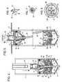
- Figure 1illustrates a syringe according to the invention before use, its rod being uncoupled.
- Figure 2shows the syringe ready for use.
- Figure 3illustrates the collection or aspiration of fluid or blood using the syringe.
- FIG. 4illustrates the state of the syringe after expulsion of blood drawn from a test tube or other container, or after injection of the liquid into the body.
- FIG. 5illustrates the syringe after use, the needle being again locked in the body and tilted.
- Figure 6is a detail of the piston hook.
- Figure 7is a top view of the rear part of the needle.
- Figure 8is a top view of the needle holder.
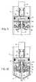
- Figure 9is a view similar to Figure 1 of a second embodiment of the syringe.
- Figure 10is a view similar to Figure 4 of the second embodiment of the syringe.
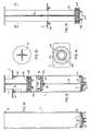
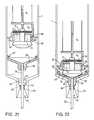
- Figures 11 to 20illustrate a third embodiment of the syringe.
- Figures 21 to 26illustrate a fourth embodiment of the syringe.
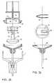
- Figures 27 and 28illustrate a variant of this fourth embodiment of the syringe.
- FIG. 29illustrates a variant of the fixing of the deformable element on the piston.
- the first embodiment of the syringe illustrated in FIGS. 1 to 5consists of a cylindrical tube 1 obtained by extrusion and produced for example from transparent polycarbonate or polypropylene. This extruded tube is cut to the desired length depending on the capacity of the syringe, its ease of use and other usual factors.
- This cylinder 1 of the syringeis closed at its proximal end by a cover also made of plastic comprising a central cylindrical part 2 fitting exactly into the cylinder 1 and a flange 3 of larger diameter.
- the cover 2,3is welded, glued or fixed in any other manner in a sealed manner on this proximal end of the cylinder 1 of the syringe.
- closure part 4molded or injected in thermoplastic resin, generally polystyrene.
- This closure part 4comprises a cylindrical part 5 with an external diameter corresponding to the internal diameter of the cylinder 1 and threaded therein.
- the external front part 6 of this closing part 4is frustoconical and provided with a central opening 7.
- This opening 7can be closed, before the use of the syringe by a stopper or then by a film peelable self-adhesive.
- This openingcan also be closed off by a portion of synthetic material produced during manufacture with the wall 6, but separated from the latter by a breaking line.
- This portionmay include a gripping member, for example a loop, making it possible to tear off this closure portion when the syringe is used to release the opening 7 giving passage to the needle.
- This closure part 4is also tightly fixed to the cylinder 1 by gluing, welding or any other suitable means.
- the closure part 4 of the distal end of the cylinder 1also has a transverse wall 8 provided with a central opening.
- a ring or cover 9 made of an elastomeris overmolded on this transverse wall 8 so as to seal the opening of this transverse wall 8 in a leaktight manner.
- This cover 9may have in its central part a zone of reduced thickness intended, as we will see it later, to be pierced by the needle of the syringe.
- This central front part of the cover 9includes a recess intended to recover any stain from the external surface of the needle during its retraction in the cylinder, thus avoiding any dispersion of this stain.
- This distal closure part 4also comprises, located inside the cylinder 1 of the syringe, a retaining flange 10 whose internal edge is bevelled, the part of smaller diameter of the opening of this flange 10 being located towards the distal end of the syringe.
- the syringealso comprises a piston formed by a rear plate 11 provided with a female part 12 of a coupling.
- This female coupling part 12passes through the central part 2 of the cover 2,3 through an orifice thereof and is accessible from the outside of the syringe.
- This female coupling part 12is intended to cooperate with the male part 13 of a corresponding coupling located at the end of a rod allowing the piston 14 to be actuated.
- the pistonalso has a cylindrical skirt 15 in its upper part, with a diameter corresponding to the internal diameter of the cylinder 1 and comprising a shoulder 16.
- the front part 17 of this skirtis frustoconical and is provided with a central orifice 18.
- the plate 11 provided with the coupling part 12 and the skirt 15, 16, 17are rigidly fixed to one another by welding, gluing, etc.
- These partsare made of thermoplastic material such as polyacetal and obtained by molding or injection.
- a "O ring" seal 19is disposed in the groove formed between the shoulder 16 of the skirt and the plate 11, thus ensuring a perfect seal between this piston 11-19 and the cylinder 1.
- This pistonalso includes a hook 20 integral with the plate 11 and extending inside the skirt 15, 17.
- This hookhas in the illustrated embodiment ( Figure 6) a flat wall 21 located in the axis of the cylinder 1 and a retaining formation constituted by a half-cone 22 whose diameter is widening towards the plate 11, semi-cone terminated by a flat face 23 slightly inclined relative to the plate 11.
- This syringealso naturally includes a hollow steel needle 24, bevelled at its distal end and provided at its proximal end with an overmolding in thermoplastic material, for example in polyacetal comprising on the one hand a disc 25 whose upper face is hollowed out so that its outer edge constitutes a retaining formation, as will be seen below and, on the other hand lamellae 26, four in the example illustrated, provided with hooks 27 at their ends.
- These flexible strips 26extend in normal position in the axis of the needle and are arranged inside a circumference whose diameter corresponds to that of the central orifice 18 of the piston so as to be able to penetrate into the internal space of the skirt 15.17 thereof. The length of these strips 26 is sufficient so that when they are fully inserted into the skirt 15, 17 of the piston, at least one of the hooks 27 hooks onto the flat face 23 of the hook 20 of the piston to permanently secure the needle 24 of this piston 11,22.
- the needle 24 and its overmolding 25, 26, 27are normally mounted on a needle holder sliding freely in the cylinder 1.
- This needle holdercomprises a rigid body 28 with a diameter corresponding to the internal diameter of the cylinder 1 provided in the direction from the proximal end of the syringe of an annular recess receiving a ring 29.
- the body 28is made of moldable or injected synthetic material such as polyacetal.
- the body 28also has at least one passage or vent 30 creating a connection between the parts of the cavity of the cylinder 1 located on either side of this needle holder so that it can slide freely in the cylinder 1.
- This movable needle holderalso includes first snap formations 31 on its distal face formed by tabs or lugs having a bevelled face and which when they are applied against the flange 10 of the distal closure part deform elastically, then snap onto this flange 10 constituting an irreversible permanent connection between the needle holder and the distal closure part.
- the needle holderfurther comprises a second snap formation 32 emerging from the body 28 in the direction of the proximal end of the syringe and cooperating with the rim of the disc 25 of the overmolding of the needle.
- These snap-on formations 32are constituted by elastically deformable tongues and provided at their ends with bosses cooperating with the edge of the disc 25. The coupling thus produced is reversible, as will be seen below the needle and its overmolding can be separated from the needle holder during syringe operation.
- the overmolding of the needle 25is coupled to the needle holder 32 with sufficient force to avoid any uncoupling of these elements during the introduction of the needle into the vein of the patient or in a muscle thereof.
- the force of this couplingmust allow the needle to be separated from the needle holder when the needle is coupled to the piston and the latter is retracted.
- the ring 29 placed in the annular recess of the body 28 of the needle holderis made of a rigid natural or synthetic material in the dry state but capable of softening on contact with a liquid which it absorbs.
- this ring 29When the syringe is new, the ring 29 is dry and hard, so it has appreciable resistance to compression.
- the height of this ring 29is such that when the piston is moved in the direction of the needle holder, the upper edge of this ring 29 abuts against the underside of the cylindrical part 15 of the skirt of the piston and that, the resistant ring 29 , the hooks 27 of the lamellae 26 of the overmolding of the needle 24 do not manage to rise sufficiently on the hook 20 of the piston to catch on the face 23 of the latter.
- the ring 29is dry and hard or rigid, it is not possible to snap the end piece 25, 26 of the needle 24 onto the hook 20 of the piston.
- this snap-fasteningis possible when the ring 29 has been softened by a liquid, because the material from which it is made loses its rigidity, its hardness and its resistance to compression.
- the syringecomprises a cylinder 1, closed at each of its ends before its use and three assemblies contained inside the cylinder, the piston 15, the needle 24 -25 and the needle holder 31-32, all three movable relative to the cylinder and to each other.
- the needle holder 31can be irreversibly coupled, not uncoupled, with the distal end of the cylinder 10; the needle can be irreversibly coupled, not decoupled, with the piston and the needle is coupled decouplably with the needle holder.
- this syringehas an element, located between the piston and the needle holder, the hardness and therefore the compressive strength decreases when it has been exposed to a liquid, this element does not allow the coupling of the needle on the piston only when its resistance has decreased following its exposure to a liquid.
- the use of the syringeis very simple, all that is required is rectilinear movements between the piston 14 and the cylinder 1. All the necessary couplings operate automatically and without the user having to be worry about the relative angular position of the parts to be coupled.
- the coupling of the needle to the plungeris automatic and irreversible, so that a second use of the syringe is impossible; Indeed, to refill the syringe, it is necessary to retract the piston, which automatically drives the needle and locks it in the cylinder.
- the piston sliding in the cylinder 1comprises a body 40 provided with a groove 41 receiving a seal.
- the upper face of this pistonis provided with the part 12 for coupling the rod 14, while the distal face of the body 40 includes a housing containing an element 42 of expanded synthetic material or of cellular natural material capable of softening on contact. of a liquid.
- a plate 43 rigidly fixed by gluing, welding, etc. against the distal face of the pistonkeeps the porous element 42 in position and has a passage whose edges are bevelled, tapering towards the element 42.
- the tabs 26 of the overmolding of the needle 24have hooks 44 intended to penetrate into the housing of the body 40 when the element 42 is softened by liquid and to be permanently coupled behind the plate 43 of the piston (FIG. 10).
- this second embodiment of the syringeis in all respects similar to that of the first embodiment described and therefore has the same advantages.
- to cause when the needle 24 is withdrawn from the cylinder its angular displacement preventing the needle from being pushed out of the cylinderit is possible to give the tongues 26 a different length or to give an inclination to the upper face. from plate 43.
- the needle 24is carried, fixedly attached to the needle holder 28. It is this needle holder 28 which has non-unlockable latching coupling formations with the distal closure part 5 as in the first embodiment. This needle holder 28 also has on its other face, directed towards the piston 40, non-unlockable snap formations cooperating with the piston.
- the variable resistance element 29is a ring carried by / or fixed on the upper face, directed towards the piston, of the needle holder.
- This third embodimentis particularly advantageous because it comprises few parts which all can be obtained by injection and their assembly can be automated.
- FIG. 11illustrates the cylinder 1 of the syringe obtained by injection in which the distal closure part 5 made up of a relatively rigid elastomer is housed.
- This distal closure parthas a central tubular extension 51 emerging from the cylinder 1 through a front hole thereof.
- This distal closure part 5is held in the service position by a bead 52 which, having been forced through the central hole of the cylinder, prevents any further separation of these two parts.
- the central tubular extension 51is before use of the syringe closed by a wall or membrane 53 intended to be pierced by the needle 24 when the latter is expelled from the cylinder 1.
- the needle 24is secured, fixed by overmolding or over-injection, to a needle holder 28.
- the distal underside of this needle holder 28has shapes corresponding to the internal, proximal face of the closure part 5.
- a conical extension 281 and snap formations 282corresponding to the opening 54 and the snap formations 55 of the distal closure part 5.
- the snap formations 55, 282make it possible to make a temporary coupling, strong enough to plant the needle 24 in a muscle or a vein of a patient or to pierce the lid of a container, but allowing uncoupling for the withdrawal of the needle 24 by the piston 40 inside the cylinder at the end of use.
- the rear or proximal face of the needle holder 28is provided with snap formations 283 arranged concentrically and providing a space receiving the variable resistance element 29 which here appears as a ring or a ring.
- the piston 40came from an injection part with its rod 14 and has on its periphery a seal 401 sealing with the cylinder 1.
- This pistonhas on its free distal face snap formations 402 intended to cooperate with the snap formations 283 of the needle holder 28 and to form therewith a non-removable and non-unlockable coupling once snapped.
- the rear end of the body or cylinder 1is closed by a plate 3 which before use of the syringe is connected by tabs which can be broken to the rod 14 of the piston. These tabs constitute a guarantee that when intact, indicate that the syringe has not been used.
- the proximal plate or obturator 3 of the syringeis fixed to the cylinder by snapping hooks 301 into holes 101 made in cylinder 1.
- Figures 13,14are respectively a section of the piston rod 14 and an end view of the distal end piston.
- FIG. 15is a view of the piston 40, of its rod 14 and of the proximal closure plate 3 before assembly with the cylinder 1.
- the distal face of the piston 40is supported on the ring 29 and drives in its movement the needle holder 28 and the needle 24.
- the needle 24pierces the elastomeric membrane 53 and the needle holder is coupled to the closure part frontal 5 ( Figures 16 and 17).
- the ring 29is dry and therefore rigid and cannot be crushed, thus avoiding any coupling of the piston 40 to the needle holder 28. From this moment, the syringe is operational, the user can either fill the cylinder with blood patient, or of a liquid contained in a bottle by moving the piston in the cylinder so as to move it away from the needle holder.
- the needle holder 28 and the needle 24are moved in the cylinder, the needle holder uncouples from the proximal closure part 5 which causes the withdrawal of the needle in the cylinder (fig. 19,20).
- the elastomeric membrane 53again seals the front end of the cylinder and the needle tilts in the cylinder under the effect of the spring leaf 284 forming part of the needle holder 28. It is therefore impossible to bring out the needle 24 from the cylinder 1.
- This inclination of the needlecan be caused by other means, for example the inherent elasticity of the ring 29 or the shape of the proximal surface of the needle holder.
- the fourth embodiment of the syringe according to the invention, fig. 21 to 26,is always based on the same principle as described above and its operation is entirely similar. However, this embodiment also comprising few parts still allows a reduction in the weight of plastic material used and a simplification of the shapes of the parts, and therefore a reduction in the cost of the syringe.
- the syringealso comprises a hollow cylinder 1 and a piston 14, the upper parts of which can be produced as in the third embodiment.
- the distal end of the cylinderhas a cylindrical extension of smaller diameter 60 having a passage whose shape is particular. Indeed, this passage, connecting the inside of the cylinder 1 to the outside of the syringe, has at its distal end a frustoconical portion 61 which tapers towards the cylinder 1 followed by a reverse sectional portion 62, widening towards cylinder 1. The intersection of these two portions 61, 62 of the passage defines a narrowing of said passage.
- This passagealso includes a third part 63 connecting the frustoconical part 62 inside the cylinder 1, part 63 of generally cylindrical shape provided with a groove 64 of larger diameter constituting one of the parts of the snap-on and snap-off coupling. between the needle holder 28 and the cylinder 1.
- the other part of this coupling, carried by the needle holder 28,is constituted by a circular bead 65 which comprises the distal end of the needle holder 28 whose shape and dimensions correspond to those of the third part 63 and at the start of the second part 62 of the passage which comprises the extension 60 of the cylinder 1.
- the zone of the passage of the extension 60 situated on either side of its constrictionis filled with an elastomeric mass 66 hermetically sealing the cylinder 1 while allowing the passage of the needle and the hermetic reclosure of the passage 61.62 , 63 the needle having been retracted into the cylinder after use.
- the proximal end of the needle holder 28has a conical shape which widens towards the piston and its peripheral surface slides without play in this cylinder 1.
- This proximal end of the needle holder 28also has snap-in functions 67 cooperating with snap formations 68 of the distal end of the piston to form a non-unlockable coupling once snapped.
- the pistonslides without play in the cylinder 1 and has a front cavity 69 and a recess 70 opening laterally.
- the wall 71 separating the front cavity 69 from the recess 70is provided with an orifice 72.
- the element whose compressive strength is lower in the wet or wet state than in the dry stateconsists of a cylinder or prism 73 pierced with a central passage 74 .
- This element 73is fixed to the piston by means of a stop 75 comprising a head 76 whose distal part is sectional and a rod 77 passing through the element 73 and the wall 71 of the piston 14.
- This rod 77has a groove 78 which in the assembled position is located in the recess 70 and receives a leaf spring 79 having a notch 80 giving passage to the rod 77 in its part of diameter reduced by the groove 78.
- the variable resistance element 73is maintained in place clamped by the spring 79 between the head 76 of the stop 75 and the wall 71 of the piston.
- the element 73softens in contact with the liquid and it is compressed by the action of the spring 79 and the stop 75 thus reducing the distance between the distal part of the 'stop 75 and the snap formations 68 of the piston.
- the pistonmates definitively with the needle holder 28 using the formations 67, 88 and when the piston is withdrawn it drives the needle holder so as to retract, as described above, the needle 24 in the cylinder 1 (FIG. 24).
- meansare provided so that at the end of retraction of the piston, the needle holder is tilted by a spring r for example to tilt the needle 24 relative to the axis of the cylinder and thus prevent it from coming out of it.
- this embodimenthas the advantage that the compressible element 73 is, when it is moistened by the liquid entering the cylinder, compressed by spring 79. This reduces the force required at the end of the injection stroke to permanently couple the piston to the needle holder.
- Figures 27 and 28illustrate a variant of this fourth embodiment relating to the fixing of the variable resistance element in the dry and wet state 73 on the piston.
- this element 73is threaded on the rod 77 of the stop 75 and the proximal end of this rod has a groove 78 and a frustoconical end 80.
- a disc 81is threaded on this rod 77 over the element 73 and a spring 83 with solid lamellae compresses the whole and is snapped in through its central orifice in the groove 78 of the rod 77.
- This disc 81comprises a circular bead 82 making it possible to couple the stop assembly 75, deformable element 73, disc 81 and spring 83 in the distal cavity 69 of the piston which comprises a circular groove 84 receiving the bead 82 of the disc 81.
- the advantage of this variantlies in the fact that the assembly formed by the stop 75, the element 73, the disc 81 and the spring 83 can be pre-assembled and stored.
- the assembly of the syringeis all the more simplified.
- FIG. 29illustrates a variant of the fixing of the compressible element 100, here of cubic shape, the compressive strength of which is greater in the dry state than in the wet or wet state.
- the distal end of the pistonhas a cylindrical wall 101 having an external rim 101a constituting the part of its coupling, which cannot be disengaged with the needle holder 28 (not illustrated) which comprises corresponding coupling members.
- the distal face of the pistonhas a housing 103 the edges of which are chamfered 104, housing divided by walls 105 serving as a stop for the compressible element 100.
- a plug 106whose distal face has the same shape as that of the stop 75 of the previous embodiment but which has a housing 109 receiving the deformable element 100 and hooks 107 allowing the fixing of this plug on a retaining shoulder 108 which comprises the cylindrical wall 101 of the piston.
- the element 100can be fixed in the dry state, uncompressed, on the distal end of the piston.
- the housing 109 of the plug 106is delimited by a wall 110 whose end is bevelled and placed so as to be able to come into contact with the bevelled edges 104 of the housing 103 of the piston when the deformable element 100 is compressed.
- the element 100is entirely trapped between the head of the piston and the plug, for example in a sealed manner.
- one more partcould be removed and the mounting of the element 100 on the piston is further facilitated.
- automatic compression of the compressible element 100can also be obtained by providing a stainless steel spring tending to bring the plug 106 closer to the piston head.
- a stainless steel springmay have the form of a cylindrical ring, for example made of stainless steel, the external wall of which is in contact with the internal surface of the cylindrical wall 101 of the piston head. This ring is held in this position by the retaining shoulder.
- This ringhas several tongues extending in the direction of the center of the ring, tongues bearing against the truncated front face of the plug 106. This front face may have recesses for this purpose.
- the tonguestend to bring together by their own elasticity the plug 106 of the distal end of the piston and therefore to compress the variable resistance element 100 as soon as the latter is softened.
Landscapes
- Health & Medical Sciences (AREA)
- Engineering & Computer Science (AREA)
- Hematology (AREA)
- Anesthesiology (AREA)
- Biomedical Technology (AREA)
- Heart & Thoracic Surgery (AREA)
- Vascular Medicine (AREA)
- Life Sciences & Earth Sciences (AREA)
- Animal Behavior & Ethology (AREA)
- General Health & Medical Sciences (AREA)
- Public Health (AREA)
- Veterinary Medicine (AREA)
- Environmental & Geological Engineering (AREA)
- Infusion, Injection, And Reservoir Apparatuses (AREA)
Abstract
Description
Translated fromFrenchLa présente invention a pour objet une seringue à usage médical, notamment une seringue d'une totale sécurité d'emploi tant pour le personnel soignant, hospitalier ou non, que pour les patients, même les patients procédant eux-mêmes à leurs injections. La seringue selon l'invention a donc pour but une utilisation de toute sécurité pour éviter notamment les risques de contamination tant du personnel soignant que des utilisateurs ou patients, facile à utiliser et à emploi unique. De plus, cette nouvelle seringue est d'un faible coût de revient.The present invention relates to a syringe for medical use, in particular a syringe of total safety of use both for the nursing staff, hospital or not, as for the patients, even the patients themselves carrying out their injections. The syringe according to the invention therefore aims to use it safely in order to avoid in particular the risks of contamination both of the nursing staff and of the users or patients, easy to use and single use. In addition, this new syringe is of low cost.
Dans ce but, l'invention consiste en une seringue munie d'une aiguille qui n'est pas apparente avant l'emploi et se trouve après l'emploi de nouveau enfermée dans le cylindre de la seringue, supprimant ainsi toute manipulation manuelle de l'aiguille, et donc tout risque de contamination.For this purpose, the invention consists of a syringe provided with a needle which is not apparent before use and is after use again enclosed in the syringe barrel, thus eliminating any manual manipulation of the needle, and therefore any risk of contamination.
Cette seringue, non réutilisable, peut ainsi être jetée après emploi, sans précautions particulières.This non-reusable syringe can thus be discarded after use, without special precautions.
Les seringues traditionnelles, bon marché et d'un maniement aisé, sont dangereuses par la possible contamination lors du capuchonnage de l'aiguille (piqûre de l'utilisateur, par exemple) ou toute autre manipulation ultérieure (débarras par exemple).Traditional, inexpensive and easy-to-use syringes are dangerous due to possible contamination when the needle is capped (needle stick, for example) or any other subsequent handling (eg ridding).
Face aux maladies transmissibles par le sang, telles que SIDA, hépatite virale, syphilis, etc. de nouvelles seringues sont apparues tendant à réduire les risques de contamination et de réutilisation. Ces seringues sont plus coûteuses et d'une manipulation plus compliquée que les seringues traditionnelles et le danger de contamination par une aiguille souillée n'est pas toujours exclu.Faced with blood-borne diseases, such as AIDS, viral hepatitis, syphilis, etc. new syringes have appeared to reduce the risk of contamination and reuse. These syringes are more expensive and more complicated to handle than traditional syringes and the danger of contamination by a contaminated needle is not always excluded.
On connait entre autre des seringues du type VACUTAINER fabriquées aux USA, VENOJECT fabriquées au Japon ou VACUETTE fabriquées en Hollande. Tous ces systèmes ne permettent que le prélèvement sanguin et nécessitent l'introduction préalable d'un collecteur à aiguille dans la veine du patient. Cette aiguille étant en place, on y connecte des récipients ou tubes mis sous vide qui se remplissent alors de sang.Among other things, we know of VACUTAINER type syringes made in the USA, VENOJECT made in Japan or VACUETTE made in Holland. All these systems only allow blood sampling and require the prior introduction of a needle collector into the patient's vein. With this needle in place, vacuum containers or tubes are connected to it, which then fill with blood.
De tels systèmes nécessitent une manipulation de l'aiguille elle-même par l'opérateur tant pour son introduction dans une veine, pour sa connexion au tube que pour la jeter après l'emploi. Toutes ces manipulations sont répétitives et de plus l'évacuation des aiguilles usagées nécessite des précautions particulières, emballages, capuchons, etc.Such systems require manipulation of the needle itself by the operator both for its introduction into a vein, for its connection to the tube and for disposing of it after use. All these manipulations are repetitive and moreover the disposal of used needles requires special precautions, packaging, caps, etc.
De plus, un tel système ne permet pas de procéder à des injections, mais seulement à des prises de sang.In addition, such a system does not allow injections, but only blood tests.
Un autre inconvénient de ce système réside dans le fait que le sang ne peut être prélevé que dans des tubes mis préalablement sous vide. Cela nécessite un prélèvement ultérieur du sang à l'aide d'une seringue traditionnelle lorsqu'on veut faire des hémocultures pour le transférer dans des récipients contenant un milieu de culture, rendant ainsi dérisoire le système sophistiqué utilisé dans le but de prévenir toute contamination.Another drawback of this system lies in the fact that the blood can only be drawn in tubes placed beforehand in a vacuum. This requires a subsequent collection of blood using a traditional syringe when blood cultures are to be transferred to containers containing a culture medium, thus making the sophisticated system used for the purpose of preventing any contamination paltry.
Lorsque plusieurs tests doivent être effectués, cela implique de répéter l'opération de prélèvement du sang à l'aide d'un tube sous vide. Ces manipulations répétées sont désagréables pour le patient qui doit supporter la présence continue du collecteur inséré dans une veine. Un autre inconvénient de ces systèmes à tube sous vide réside dans le fait que ces tubes doivent être en verre et sont donc cassables.When several tests have to be carried out, this involves repeating the operation of drawing the blood using a vacuum tube. These repeated manipulations are unpleasant for the patient who must endure the continuous presence of the collector inserted in a vein. Another disadvantage of these vacuum tube systems lies in the fact that these tubes must be made of glass and are therefore breakable.
Enfin, le prélèvement de sang à l'aide du vacuum du tube peut, sous certaines circonstances particulières, provoquer l'éclatement des globules rouges ou l'obstruction d'une veine par collapse de ses parois puisqu'il est impossible d'ajuster le taux de succion ou du vacuum aux conditions particulières du patient.Finally, the drawing of blood using the vacuum of the tube can, under certain particular circumstances, cause the bursting of red blood cells or the obstruction of a vein by collapse of its walls since it is impossible to adjust the suction or vacuum rate at specific patient conditions.
Bien que le personnel médical et para-médical se soit habitué à l'emploi des systèmes utilisant les éprouvettes à vide, ils ont néanmoins toujours gardé une préférence pour la simplicité de la seringue traditionnelle. Or, avec l'invention en question, toute la simplicité des seringues traditionnelles est présente, mais sans risques d'infection pour l'utilisateur.Although medical and paramedical personnel have become accustomed to the use of systems using vacuum test tubes, they have nevertheless always kept a preference for the simplicity of the traditional syringe. However, with the invention in question, all the simplicity of traditional syringes is present, but without risk of infection for the user.
On connaît également le système MONOVETTE fabriqué en Allemagne qui est semblable au système VACUTAINER au fait près que les tubes collecteurs sous vide sont remplacés par des cylindres munis de pistons à l'instar d'une seringue traditionnelle. Les risques de contamination sont ici également grands.We also know the MONOVETTE system made in Germany which is similar to the VACUTAINER system except that the vacuum collecting tubes are replaced by cylinders fitted with pistons like a traditional syringe. The risks of contamination are also great here.
On connaît du document WO 90/06148 une seringue comportant un corps tubulaire à l'intérieur duquel se déplacent linéairement un piston et un porte-aiguille, le piston et le porte-aiguille pouvant être accouplés et désaccouplés. Avant usage, l'aiguille est logée dans le corps tubulaire, elle en est extraite par un déplacement du porte-aiguille sous l'action du piston, contre l'action d'un ressort, et est maintenue en position sortie, opérationnelle, par encliquetage du porte-aiguille sur un épaulement interne du corps. Une fois dans cette position, la seringue peut être utilisée et réutilisée autant de fois que l'on veut. En accouplant le piston au porte-aiguille, il est possible de retirer volontairement celle-ci dans le corps, mais cet escamotage de l'aiguille doit être volontaire et n'est pas automatique. De plus, le système est compliqué et onéreux. Cette seringue ne peut en outre pas être pré-stérilisée sans opération complémentaire puisqu'elle est ouverte à l'avant.Document WO 90/06148 discloses a syringe comprising a tubular body inside which a piston and a needle holder move linearly, the piston and the needle holder being able to be coupled and uncoupled. Before use, the needle is housed in the tubular body, it is extracted therefrom by a displacement of the needle holder under the action of the piston, against the action of a spring, and is held in the extended, operational position, by snap-fastening of the needle holder on an internal shoulder of the body. Once in this position, the syringe can be used and reused as many times as desired. By coupling the piston to the needle holder, it is possible to voluntarily remove it in the body, but this retraction of the needle must be voluntary and is not automatic. In addition, the system is complicated and expensive. This syringe can also not be pre-sterilized without additional operation since it is open at the front.
On connaît des documents EP 0 326 983 et EP 0 347 742 des seringues qui permettent également de retirer volontairement à la fin de son utilisation l'aiguille dans le corps de la seringue. Ici également, cette opération est volontaire et non automatique ce qui autorise une utilisation répétée de la seringue. De plus, avant usage, l'aiguille de la seringue est située hors du corps et ne peut donc pas être pré-stérilisée sans protection supplémentaire.EP 0 326 983 and EP 0 347 742 disclose syringes which also allow the needle to be withdrawn voluntarily at the end of its use in the body of the syringe. Here too, this operation is voluntary and not automatic, which allows repeated use of the syringe. In addition, before use, the syringe needle is located outside the body and therefore cannot be pre-sterilized without additional protection.
Les mêmes inconvénients se retrouvent dans les seringues décrites dans les documents US 4.507.117 et US 4.675.005, car en effet la seringue ne peut pas être préstérilisée sans protection supplémentaire puisque l'aiguille est hors du corps de la seringue avant usage et nécessite un capuchon et que d'autre part le retrait de l'aiguille dans le corps de la seringue résulte d'une action volontaire, de sorte que la seringue est réutilisable. Cette seringue fait usage d'un mécanisme à ressort métallique et l'aiguille ne peut pas être séparée du porte-aiguille. De plus, pour retirer l'aiguille on doit effectuer une manipulation bi-directionelle provoquant un déplacement axial et rotatif du piston. Enfin, le coût de fabrication est élevé.The same drawbacks are found in the syringes described in documents US Pat. No. 4,507,117 and US 4,675,005, since the syringe cannot in fact be pre-sterilized without additional protection since the needle is outside the body of the syringe before use and requires a cap and that on the other hand the withdrawal of the needle in the body of the syringe results from a voluntary action, so that the syringe is reusable. This syringe makes use of a spring mechanism metal and the needle cannot be separated from the needle holder. In addition, to withdraw the needle, bi-directional manipulation must be carried out, causing axial and rotary displacement of the piston. Finally, the manufacturing cost is high.
La présente invention a pour objet une seringue tendant à obvier aux inconvénients des seringues connues et permettant de résoudre de façon simple, efficace, incontournable et peu coûteuse, notamment les problèmes suivants :
- 1. Avant emploi, la seringue et son aiguille doivent être pré-stérilisables sans devoir être obligatoirement enfermée dans un
emballage. - 2. La seringue doit avant emploi avoir son aiguille enfermée hermétiquement à l'intérieur du corps.
- 3. La seringue doit pouvoir être utilisée tant pour des prises de sang que pour des injections de produits.
- 4. Après un seul et unique usage de la seringue, l'aiguille doit, après retrait par un mouvement linéaire seulement dans le corps de la seringue, ne plus pouvoir en être extraite, ce qui prévient toute contamination ultérieure et garantit un usage unique.
- 1. Before use, the syringe and its needle must be pre-sterilizable without having to be necessarily enclosed in a
packaging. - 2. Before use, the syringe must have its needle sealed inside the body.
- 3. The syringe must be capable of being used both for blood tests and for injecting products.
- 4. After a single use of the syringe, the needle must, after withdrawal by a linear movement only in the body of the syringe, no longer be able to be extracted therefrom, which prevents any subsequent contamination and guarantees a single use.
La seringue à usage médical non réutilisable selon l'invention obviant aux inconvénients précités et permettant de résoudre les problèmes énumérés ci-dessus se distingue par les caractéristiques énumérées à la revendication 1.The non-reusable syringe for medical use according to the invention which overcomes the aforementioned drawbacks and makes it possible to solve the problems listed above is distinguished by the characteristics listed in
Les dessins annexés illustrent schématiquement et à titre d'exemple des formes d'exécution de la seringue selon l'invention.The accompanying drawings illustrate schematically and by way of example embodiments of the syringe according to the invention.
La figure 1 illustre une seringue selon l'invention avant emploi, sa tige étant désaccouplée.Figure 1 illustrates a syringe according to the invention before use, its rod being uncoupled.
La figure 2 illustre la seringue prête à l'emploi.Figure 2 shows the syringe ready for use.
La figure 3 illustre le prélèvement ou aspiration de liquide ou de sang à l'aide de la seringue.Figure 3 illustrates the collection or aspiration of fluid or blood using the syringe.
La figure 4 illustre l'état de la seringue après expulsion du sang prélevé dans une éprouvette ou autre récipient, ou après injection du liquide dans le corps.FIG. 4 illustrates the state of the syringe after expulsion of blood drawn from a test tube or other container, or after injection of the liquid into the body.
La figure 5 illustre la seringue après usage l'aiguille étant à nouveau enfermée dans le corps et inclinée.FIG. 5 illustrates the syringe after use, the needle being again locked in the body and tilted.
La figure 6 est un détail du crochet du piston.Figure 6 is a detail of the piston hook.
La figure 7 est une vue de dessus de la partie arrière de l'aiguille.Figure 7 is a top view of the rear part of the needle.
La figure 8 est une vue de dessus du porte-aiguille.Figure 8 is a top view of the needle holder.
La figure 9 est une vue similaire à la figure 1 d'une seconde forme d'exécution de la seringue.Figure 9 is a view similar to Figure 1 of a second embodiment of the syringe.
La figure 10 est une vue similaire à la figure 4 de la seconde forme d'exécution de la seringue.Figure 10 is a view similar to Figure 4 of the second embodiment of the syringe.
Les figures 11 à 20 illustrent une troisième forme d'exécution de la seringue.Figures 11 to 20 illustrate a third embodiment of the syringe.
Les figures 21 à 26 illustrent une quatrième forme d'exécution de la seringue.Figures 21 to 26 illustrate a fourth embodiment of the syringe.
Les figures 27 et 28 illustrent une variante de cette quatrième forme d'exécution de la seringue.Figures 27 and 28 illustrate a variant of this fourth embodiment of the syringe.
La figure 29 illustre une variante de la fixation de l'élément déformable sur le piston.FIG. 29 illustrates a variant of the fixing of the deformable element on the piston.
La présente invention a pour objet une seringue à usage médical non réutilisable, pouvant servir soit pour le prélèvement de liquide, généralement du sang, soit pour l'injection d'une solution médicamenteuse ou autre. Comme on le verra de la description détaillée qui suit, cette seringue présente de très nombreux avantages par rapport aux seringues existantes, ainsi que par rapport à celles, pour la plupart non commercialisées, qui sont décrites dans les documents antérieurs discutés dans l'introduction. Ces principaux avantages sont notamment :
- 1. L'aiguille fait partie intégrante de la seringue et ne peut pas être séparée de celle-ci évitant toute manipulation directe de cette aiguille, telles que fixation, capuchonnage, rangement, etc.
- 2. Avant emploi, l'aiguille est protégée à l'intérieur du cylindre qui est fermé hermétiquement. De ce fait, l'ensemble de la seringue peut être stérilisé après fabrication et montage, par exemple par des rayonnements ionisants, et ne nécessite pas d'emballage particulier.
- 3. En fin d'utilisation, l'aiguille, éventuellement désolidarisée du porte-aiguille, est prise par le piston ce qui permet sa rétractation automatique à l'intérieur du cylindre par le mouvement linéaire du piston. Ainsi, non seulement l'utilisateur est protégé contre toute contamination ou infection, mais toute surface à l'extérieur de la seringue n'étant pas souillée, elle peut être simplement jetée ou mise au rebut sans précaution particulière, toute pièce contaminée ou souillée étant hermétiquement contenue dans le cylindre. Un usage vraiment unique de la seringue est assuré, l'aiguille étant automatiquement biaisée une fois rétractée dans le cylindre et ne pouvant plus, même volontairement, être ressortie.
- 4. En fin d'utilisation, le piston est définitivement solidaire de l'aiguille ce qui interdit toute réutilisation de la seringue.
- 5. Un cône à l'extrémité du cylindre empêche tout risque de contamination par une éventuelle souillure de sang restée sur la surface extérieure du diaphragme élastomérique.
- 6. En fin d'utilisation, la tige du piston peut être cassée à l'extérieur de la seringue pour en réduire l'encombrement offrant ainsi une autre garantie de non réutilisation.
- 7. L'utilisation de la seringue est extrêmement simple, elle consiste uniquement en un mouvement de va et vient rectiligne du piston dans le cylindre à l'aide d'une tige et ceci sans rotation, vissage, dévissage ou positionnement angulaire d'une pièce par rapport à une autre pour actionner un accouplement.
- 8. Une fois utilisée, la seringue peut être jetée sans précautions spéciales, sa surface extérieure n'est pas contaminée, toute souillure restant hermétiquement à l'intérieur.
- 9. Enfin, la construction de la seringue est simple faisant appel à des techniques bien connues et peu onéreuses. Elle est entièrement réalisée en matières plastiques extrudées, moulées ou injectées, à l'exception de l'aiguille ou d'un éventuel ressort bien entendu, ce qui permet une fabrication en grande série, à haute cadence et à bas prix. Son montage est simple, se prête à l'automation et ne fait pas appel à de la main d'oeuvre qualifiée.
Sa construction et son montage sont simples, généralement sans ressorts, et sans mécanisme compliqué, peu coûteux et appropriés pour une production industrielle.
- 1. The needle is an integral part of the syringe and cannot be separated from the latter avoiding any direct manipulation of this needle, such as fixing, capping, storage, etc.
- 2. Before use, the needle is protected inside the cylinder which is hermetically closed. Therefore, the entire syringe can be sterilized after manufacture and assembly, for example by ionizing radiation, and does not require any special packaging.
- 3. At the end of use, the needle, possibly separated from the needle holder, is taken by the piston which allows its automatic retraction inside the cylinder by the linear movement of the piston. Thus, not only is the user protected against any contamination or infection, but any surface outside the syringe not being soiled, it can be simply thrown away or discarded without special precautions, any contaminated or soiled part being hermetically contained in the cylinder. A truly unique use of the syringe is ensured, the needle being automatically biased once retracted into the cylinder and no longer able, even voluntarily, come out.
- 4. At the end of use, the plunger is permanently secured to the needle, which prevents any re-use of the syringe.
- 5. A cone at the end of the cylinder prevents any risk of contamination by possible staining of blood remaining on the outer surface of the elastomeric diaphragm.
- 6. At the end of use, the plunger rod can be broken outside the syringe to reduce its bulk thus providing another guarantee of non-reuse.
- 7. The use of the syringe is extremely simple, it consists only of a straight back and forth movement of the piston in the cylinder using a rod and this without rotation, screwing, unscrewing or angular positioning of a part relative to another to actuate a coupling.
- 8. Once used, the syringe can be discarded without special precautions, its outside surface is not contaminated, any stain remaining hermetically inside.
- 9. Finally, the construction of the syringe is simple using well-known and inexpensive techniques. It is entirely made of extruded, molded or injected plastics, with the exception of the needle or a possible spring of course, which allows mass production, at high speed and at low cost. Its assembly is simple, lends itself to automation and does not require skilled labor.
Its construction and assembly are simple, generally without springs, and without complicated mechanism, inexpensive and suitable for industrial production.
En référence aux dessins, la première forme d'exécution de la seringue illustrée aux figures 1 à 5 est constituée par un tube cylindrique 1 obtenu par extrusion et réalisé par exemple en polycarbonate ou polypropylène transparent. Ce tube extrudé est sectionné à la longueur désirée dépendant de la capacité de la seringue, de sa commodité d'utilisation et d'autres facteurs habituels.With reference to the drawings, the first embodiment of the syringe illustrated in FIGS. 1 to 5 consists of a
Ce cylindre 1 de la seringue est obturé à son extrémité proximale par un couvercle également en matière plastique comportant une partie cylindrique centrale 2 s'emboîtant exactement dans le cylindre 1 et une collerette 3 de plus grand diamètre. En position assemblée, le couvercle 2,3 est soudé, collé ou fixé de toute autre manière de façon étanche sur cette extrémité proximale du cylindre 1 de la seringue.This
L'autre extrémité, l'extrémité distale du cylindre 1 est obturée par une pièce de fermeture 4 moulée ou injectée en résine thermoplastique, généralement du polystyrène. Cette pièce de fermeture 4 comporte une partie cylindrique 5 d'un diamètre externe correspondant au diamètre interne du cylindre 1 et enfilée dans celui-ci. La partie frontale extérieure 6 de cette pièce de fermeture 4 est tronconique et munie d'une ouverture centrale 7.The other end, the distal end of the
Cette ouverture 7 peut être obturée, avant l'emploi de la seringue par un bouchon ou alors par une pellicule auto-collante pelable. On peut également obturer cette ouverture par une portion de matière synthétique venue de fabrication avec la paroi 6, mais séparée de celle-ci par une ligne de rupture. Cette portion peut comporter un organe de préhension, par exemple une boucle, permettant d'arracher cette portion d'obturation au moment de l'utilisation de la seringue pour libérer l'ouverture 7 donnant passage à l'aiguille.This opening 7 can be closed, before the use of the syringe by a stopper or then by a film peelable self-adhesive. This opening can also be closed off by a portion of synthetic material produced during manufacture with the
Cette pièce de fermeture 4 est également fixée de façon étanche sur le cylindre 1 par collage, soudage ou tout autre moyen adéquat.This
Etant donné que les matières constituant le cylindre 1, le couvercle 2,3 et la pièce de fermeture 4 sont compatibles et thermoformables, leur assemblage peut se faire par "spin welding" ou soudure par friction ce qui est très simple et rapide.Since the materials constituting the
La pièce de fermeture 4 de l'extrémité distale du cylindre 1 comporte encore une paroi transversale 8 munie d'une ouverture centrale. Une bague ou opercule 9 en un élastomère est surmoulée sur cette paroi transversale 8 de manière à obturer de façon étanche l'ouverture de cette paroi transversale 8. Cet opercule 9 peut comporter dans sa partie centrale une zone de plus faible épaisseur destinée, comme on le verra plus loin, à être percée par l'aiguille de la seringue. Cette partie frontale centrale de l'opercule 9 comporte une creusure destinée à récupérer toute souillure de la surface externe de l'aiguille lors de sa rétraction dans le cylindre évitant ainsi toute dispersion de cette souillure.The
Cette pièce de fermeture distale 4 comporte encore, située à l'intérieur du cylindre 1 de la seringue, une collerette de retenue 10 dont le bord interne est biseauté, la partie de plus faible diamètre de l'ouverture de cette collerette 10 étant située vers l'extrémité distale de la seringue.This
La seringue comporte encore un piston formé d'une plaque arrière 11 munie d'une partie femelle 12 d'un accouplement. Cette partie femelle d'accouplement 12 traverse la partie centrale 2 du couvercle 2,3 par un orifice de celui-ci et est accessible de l'extérieur de la seringue. Cette partie femelle d'accouplement 12 est destinée à coopérer avec la partie mâle 13 d'un accouplement correspondant situé à l'extrémité d'une tige permettant l'actionnement du piston 14.The syringe also comprises a piston formed by a
Le piston comporte encore une jupe 15 cylindrique dans sa partie supérieure, d'un diamètre correspondant au diamètre interne du cylindre 1 et comportant un épaulement 16. La partie frontale 17 de cette jupe est tronconique et est munie d'un orifice central 18. La plaque 11 munie de la partie d'accouplement 12 et la jupe 15,16,17 sont fixées rigidement l'une à l'autre par soudage, collage, etc. Ces parties sont réalisées en matière thermoplastique telle que du polyacétal et obtenues par moulage ou injection. Un joint "O ring" 19 est disposé dans la gorge ménagée entre l'épaulement 16 de la jupe et la plaque 11 assurant ainsi une étanchéité parfaite entre ce piston 11-19 et le cylindre 1.The piston also has a
Ce piston comporte encore un crochet 20 solidaire de la plaque 11 et s'étendant à l'intérieur de la jupe 15, 17. Ce crochet présente dans l'exécution illustrée (figure 6) une paroi plane 21 située dans l'axe du cylindre 1 et une formation de retenue constituée par un demi-cône 22 dont le diamètre va en s'élargissant en direction de la plaque 11, demi-cône terminé par une face plane 23 légèrement inclinée par rapport à la plaque 11.This piston also includes a
Cette seringue comporte encore bien entendu une aiguille creuse 24 en acier, biseautée à son extrémité distale et munie à son extrémité proximale d'un surmoulage en matière thermoplastique, par exemple en polyacétal comprenant d'une part un disque 25 dont la face supérieure est creusée de manière à ce que son bord externe constitue une formation de retenue, comme on le verra plus loin et, d'autre part des lamelles 26, quatre dans l'exemple illustré, munies de crochets 27 à leurs extrémités. Ces lamelles 26 flexibles s'étendent en position normale dans l'axe de l'aiguille et sont disposées à l'intérieur d'une circonférence dont le diamètre correspond à celui de l'orifice central 18 du piston de manière à pouvoir pénétrer dans l'espace interne de la jupe 15,17 de celui-ci. La longueur de ces lamelles 26 est suffisante pour que lorsqu'elles sont introduites à fond dans la jupe 15, 17 du piston, au moins un des crochets 27 vienne se crocher sur la face plane 23 du crochet 20 du piston pour solidariser définitivement l'aiguille 24 de ce piston 11,22.This syringe also naturally includes a
L'aiguille 24 et son surmoulage 25,26,27 sont normalement montés sur un porte-aiguille coulissant librement dans le cylindre 1. Ce porte-aiguille comporte un corps rigide 28 d'un diamètre correspondant au diamètre interne du cylindre 1 muni en direction de l'extrémité proximale de la seringue d'un évidement annulaire recevant une bague 29. Le corps 28 est en matière synthétique moulable ou injectée telle que du polyacétal. Le corps 28 comporte encore au moins un passage ou évent 30 créant une liaison entre les parties de la cavité du cylindre 1 situées de part et d'autre de ce porte-aiguille de façon à ce que celui-ci puisse coulisser librement dans le cylindre 1.The
Ce porte-aiguille mobile comporte encore des premières formations d'encliquetage 31 sur sa face distale constituée par des pattes ou ergots présentant une face biseautée et qui lorsqu'ils sont appliqués contre la collerette 10 de la pièce de fermeture distale se déforment élastiquement, puis s'encliquettent sur cette collerette 10 constituant une liaison permanente irréversible entre le porte-aiguille et la pièce de fermeture distale.This movable needle holder also includes
Le porte-aiguille comporte encore une seconde formation d'encliquetage 32 émergeant du corps 28 en direction de l'extrémité proximale de la seringue et coopérant avec le rebord du disque 25 du surmoulage de l'aiguille. Ces formations d'encliquetage 32 sont constituées par des languettes déformables élastiquement et munies à leurs extrémités de bossages coopérant avec le rebord du disque 25. L'accouplement ainsi réalisé est réversible, comme on le verra plus loin l'aiguille et son surmoulage pouvant être séparés du porte-aiguille lors du fonctionnement de la seringue.The needle holder further comprises a
En effet, il faut que le surmoulage 25 de l'aiguille soit accouplé au porte-aiguille 32 avec une force suffisante pour éviter tout désaccouplement de ces éléments lors de l'introduction de l'aiguille dans la veine du patient ou dans un muscle de celui-ci. Par contre, la force de cet accouplement doit permettre la séparation de l'aiguille du porte-aiguille lorsque l'aiguille est accouplée au piston et que celui-ci est rétracté.Indeed, it is necessary that the overmolding of the
La bague 29 placée dans l'évidement annulaire du corps 28 du porte-aiguille est réalisée en une matière naturelle ou synthétique rigide à l'état sec mais susceptible de ramollir au contact d'un liquide qu'elle absorbe.The
Lorsque la seringue est neuve, la bague 29 est sèche et dure, elle présente donc une résistance appréciable à la compression. La hauteur de cette bague 29 est telle que lorsque le piston est déplacé en direction du porte-aiguille, la tranche supérieure de cette bague 29 bute contre la face inférieure de la partie cylindrique 15 de la jupe du piston et que, la bague 29 résistant, les crochets 27 des lamelles 26 du surmoulage de l'aiguille 24 n'arrivent pas à remonter suffisamment sur le crochet 20 du piston pour s'accrocher sur la face 23 de celui-ci. Ainsi lorsque la bague 29 est sèche et dure ou rigide, il n'est pas possible d'encliqueter l'embout 25,26 de l'aiguille 24 sur le crochet 20 du piston. Comme on le verra plus loin, cet encliquetage est possible lorsque la bague 29 aura été ramollie par un liquide, car la matière dont elle est réalisée perd sa rigidité, sa dureté et sa résistance à la compression.When the syringe is new, the
Comme on l'a vu de cette description détaillée de la seringue, celle-ci comporte un cylindre 1, obturé à chacune de ses extrémités avant son usage et trois ensembles contenus à l'intérieur du cylindre, le piston 15, l'aiguille 24-25 et le porte-aiguille 31-32, tous trois déplaçables par rapport au cylindre et les uns par rapport aux autres. De plus, le porte-aiguille 31 est accouplable de façon irréversible, non désaccouplable, avec l'extrémité distale du cylindre 10; l'aiguille peut être accouplée de façon irréversible, non découplable, avec le piston et l'aiguille est accouplée de façon découplable avec le porte-aiguille.As we have seen from this detailed description of the syringe, it comprises a
Enfin, cette seringue comporte un élément, situé entre le piston et le porte-aiguille, dont la dureté et donc la résistance à la compression diminue lorsqu'il a été exposé à un liquide, cet élément n'autorisant l'accouplement de l'aiguille sur le piston que lorsque sa résistance a diminué consécutivement à son exposition à un liquide.Finally, this syringe has an element, located between the piston and the needle holder, the hardness and therefore the compressive strength decreases when it has been exposed to a liquid, this element does not allow the coupling of the needle on the piston only when its resistance has decreased following its exposure to a liquid.
Le fonctionnement de la seringue décrite est le suivant :
- 1. L'usager prend une seringue stérile, neuve, telle qu'illustrée à la figure 1, si la tige ne fait pas partie intégrante du piston il accouple la tige 14 sur le piston 11-23 de la seringue à l'aide de l'accouplement à l'encliquetage 12,13 et dégage l'ouverture 7.
- 2. En appuyant sur la tige 14 et en maintenant le corps de la seringue par la collerette 3, l'usager déplace le piston 11-23 en direction de l'extrémité distale de la seringue. Ce faisant, la partie cylindrique 15 de la jupe du cylindre vient s'appuyer sur la bague 29, rigide et résistante puisque sèche, du porte-aiguille 28-32 et entraîne de ce fait ce porte-aiguille, ainsi que l'aiguille 24-26 qui lui est accouplée. Ce faisant l'extrémité biseautée et aiguisée de l'aiguille 24 perce l'opercule en élastomère 9, l'aiguille sort du cylindre 1.
L'usager continue de déplacer le piston vers l'extrémité distale de la seringue jusqu'à ce que le porte-aiguille soit encliqueté, et donc relié rigidement et de façon non démontable, sur la pièce de fermeture distale 4 par le crochetage des ergots 31 venant se placer sous la collerette 10 (voir figure 2). Pendant ce déplacement du piston, du porte-aiguille et de l'aiguille, l'air contenu dans le cylindre traverse le porte-aiguille par les passages ou évents 30 et sort de la seringue par le trou central de l'aiguille 24. Comme on le voit sur la figure 2, le surmoulage de l'aiguille 24 n'a pas pu s'encliqueter sur le piston parce que la distance séparant le piston du porte-aiguille est maintenue à une valeur suffisante par la bague 29. Il est à remarquer que dans cette position une étanchéité parfaite est assurée entre la face frontale du porte-aiguille et l'opercule 9 en matière élastomère donc compressible élastiquement. - 3. L'usager place l'aiguille 24 soit dans un récipient, flacon, éprouvette, etc. où un liquide doit être prélevé, ou introduit cette aiguille dans la veine d'un patient, puis en déplaçant le piston 12-23 vers l'extrémité proximale de la seringue, il aspire le liquide ou le sang, à travers l'aiguille dans le cylindre 1 entre le porte-aiguille, définitivement fixé au cylindre, et le piston (figure 3). Arrivé en fin de course du piston ou ayant prélevé la quantité de liquide ou de sang voulu, l'usager retire l'aiguille du récipient ou de la veine du patient.
- 4. Ensuite, si l'on a prélevé du sang d'un patient, l'usager place l'aiguille dans une éprouvette ou si la seringue a été remplie d'un liquide, l'usager introduit l'aiguille dans la veine, le muscle, etc. d'un patient. L'usager déplace alors le piston en direction de l'extrémité distale de la seringue vidant le contenu de celle-ci soit dans une ou plusieurs éprouvettes, soit dans la veine, le muscle, etc. du patient. Arrivé en fin de course (figure 4), la bague 29 du porte-aiguille s'étant ramollie au contact du liquide ou du sang contenu dans la seringue, le piston se déplace jusqu'à ce que la partie conique 17 de la jupe bute contre le disque 25 du surmoulage de l'aiguille et que au moins un des crochets 27 des lamelles 26 de ce surmoulage vienne se crocheter sur la
face 23 ducrochet 20 du piston. Ce faisant, les secondesformations 32 du porte-aiguille ont été écartées parla portion tronconique 17 de la jupe du piston et lorsque l'usager déplace à nouveau le piston en direction de l'extrémité proximale de la seringue, celui-ci entraîne l'aiguille, qui se sépare du porte-aiguille, avec lui. Arrivé en fin de course (figure 5),l'aiguille 24 est entièrement rétractée dans le cylindre 1, son extrémité est située au-dessus du porte-aiguille définitivement fixé à la pièce de fermeture distale.L'opercule 9 en élastomère se referme, de sorte que le cylindre de la seringue est à nouveau étanche.
En outre, du fait de la forme conique du crochet 20 du piston et de son décalage par rapport à l'axe du cylindre, l'aiguille s'incline sous l'action élastique des lamelles 26 de manière à former un angle par exemple de 5° à 7°, par rapport à l'axe du cylindre. Ceci interdit formellement toute possibilité de faire ressortir l'aiguille usagée du cylindre de la seringue. Pour encore augmenter ou assurer cet effet d'inclinaison de l'aiguille, il est possible de donner à la face inférieure de la jupe 17 du piston une inclinaison pour que cette face frontale soit par exemple parallèle à laface d'accrochage 23 ducrochet 20. Ainsi, l'appui de la jupe 17 sur le disque 25 du surmoulage de l'aiguille force également à un décalage angulaire de l'aiguille en position rétractée.
- 1. The user takes a new sterile syringe, as illustrated in FIG. 1, if the rod is not an integral part of the plunger, he couples the
rod 14 on the plunger 11-23 of the syringe using thesnap coupling - 2. By pressing on the
rod 14 and holding the syringe body by thecollar 3, the user moves the piston 11-23 in the direction of the distal end of the syringe. In doing so, thecylindrical part 15 of the cylinder skirt comes to bear on thering 29, rigid and resistant since dry, of the needle holder 28-32 and thereby drives this needle holder, as well as the needle 24 -26 which is mated to it. In doing so the beveled and sharpened end of theneedle 24 pierces theelastomeric seal 9, the needle leaves thecylinder 1.
The user continues to move the plunger towards the distal end of the syringe until the needle holder is snapped on, and therefore rigidly and non-detachably connected, on thedistal closure part 4 by hooking thepins 31 being placed under the flange 10 (see Figure 2). During this movement of the piston, the needle holder and the needle, the air contained in the cylinder passes through the needle holder through the passages orvents 30 and leaves the syringe through the central hole of theneedle 24. As As can be seen in FIG. 2, the overmolding of theneedle 24 could not snap onto the piston because the distance separating the piston from the needle holder is maintained at a sufficient value by thering 29. It is note that in this position a perfect seal is ensured between the front face of the needle holder and thecover 9 made of elastomeric material therefore elastically compressible. - 3. The user places
needle 24 either in a container, vial, test tube, etc. where a liquid is to be withdrawn, or introduces this needle into the vein of a patient, then by moving the plunger 12-23 towards the proximal end of the syringe, it draws up the liquid or the blood, through the needle incylinder 1 between the needle holder, permanently fixed to the cylinder, and the piston (Figure 3). At the end of the piston stroke or having withdrawn the required quantity of liquid or blood, the user withdraws the needle from the container or patient's vein. - 4. Then, if blood has been taken from a patient, the user places the needle in a test tube or if the syringe has been filled with a liquid, the user introduces the needle into the vein, muscle, etc. of a patient. The user then moves the piston in the direction of the distal end of the syringe emptying the contents thereof either in one or more test tubes, or in the vein, muscle, etc. of the patient. At the end of the stroke (Figure 4), the
ring 29 of the needle holder having softened in contact with the liquid or the blood contained in the syringe, the piston moves until theconical part 17 of the skirt stops against thedisc 25 of the overmolding of the needle and that at least one of thehooks 27 of thelamellae 26 of this overmolding is hooked onto theface 23 of thehook 20 of the piston. In doing so, thesecond formations 32 of the needle holder have been moved aside by thefrustoconical portion 17 of the skirt of the piston and when the user again moves the piston in the direction of the proximal end of the syringe, this causes the needle, which separates from the needle holder, with it. Arrived at the end of the race (Figure 5), theneedle 24 is fully retracted in thecylinder 1, its end is located above the needle holder permanently fixed to the distal closure part. Theelastomeric seal 9 closes, so that the syringe cylinder is again sealed.
In addition, due to the conical shape of thehook 20 of the piston and its offset relative to the axis of the cylinder, the needle tilts under the elastic action of thelamellae 26 so as to form an angle, for example from 5 ° to 7 °, relative to the axis of the cylinder. This formally prohibits any possibility of bringing the used needle out of the syringe barrel. To further increase or ensure this inclination effect of the needle, it is possible to give the underside of theskirt 17 of the piston an inclination so that this front face is for example parallel to the hookingface 23 of thehook 20. Thus, the support of theskirt 17 on thedisc 25 of the overmolding of the needle also forces an angular offset of the needle in the retracted position.
Comme on le voit, pour l'usager l'utilisation de la seringue est très simple, il suffit de mouvements rectilignes entre le piston 14 et le cylindre 1. Tous les accouplements nécessaires fonctionnent automatiquement et sans que l'usager n 'ait à se préoccuper de la position angulaire relative des pièces à accoupler. En fin de course d'expulsion du liquide contenu dans la seringue, l'accouplement de l'aiguille au piston est automatique et irréversible, de sorte qu'une seconde utilisation de la seringue est impossible; en effet, pour reremplir la seringue, il faut rétracter le piston, ce qui entraîne automatiquement l'aiguille et la verrouille dans le cylindre.As we can see, for the user the use of the syringe is very simple, all that is required is rectilinear movements between the
Comme tous les éléments qui sont entrés en contact avec le sang ou un autre liquide et qui donc peuvent être contaminés sont en fin de processus enfermés de façon hermétique, la seringue peut être jetée sans autre précaution.As all the elements which have come into contact with blood or another liquid and which therefore can be contaminated are at the end of the process hermetically sealed, the syringe can be discarded without other precautions.
On remarque encore que pendant et après l'utilisation les deux mains de l'opérateur sont toujours du côté proximal donc non dangereux de la seringue, une main pour tenir le cylindre et l'autre pour tirer le piston qui entraîne l'aiguille à l'intérieur du cylindre. Les autres systèmes exigent qu'une des mains opère du côté distal de la seringue ou du collecteur afin de couvrir avec un capuchon l'aiguille souillée voire la dévisser du corps de la seringue, moment le plus dangereux à cause du risque de blessure et de contamination de l'utilisateur. La présente seringue est donc beaucoup plus sûre que les systèmes existants.We also note that during and after use both hands of the operator are always on the proximal side therefore non-dangerous from the syringe, one hand to hold the cylinder and the other to pull the piston which drives the needle to the inside the cylinder. Other systems require that one hand operate on the distal side of the syringe or collector in order to cover the soiled needle with a cap or even unscrew it from the body of the syringe, the most dangerous moment because of the risk of injury and user contamination. The present syringe is therefore much safer than existing systems.
Dans la seconde forme d'exécution de la seringue illustrée aux figures 9 et 10, on retrouve pratiquement tous les éléments déjà décrits, seul l'accouplement entre le piston et l'aiguille, ainsi que la position de l'élément à dureté ou résistance modifiable sont différents.In the second embodiment of the syringe illustrated in Figures 9 and 10, we find almost all the elements already described, only the coupling between the piston and the needle, as well as the position of the element with hardness or resistance editable are different.
Dans cette exécution, le piston coulissant dans le cylindre 1 comporte un corps 40 muni d'une gorge 41 recevant un joint d'étanchéité. La face supérieure de ce piston est munie de la partie 12 d'accouplement de la tige 14, tandis que la face distale du corps 40 comporte un logement renfermant un élément 42 en matière synthétique expansée ou en matière naturelle cellulaire capable de se ramollir au contact d'un liquide. Une plaque 43 fixée rigidement par collage, soudure, etc. contre la face distale du piston maintient l'élément poreux 42 en position et comporte un passage dont les bords sont biseautés allant en se rétrécissant en direction de l'élément 42.In this embodiment, the piston sliding in the
Les languettes 26 du surmoulage de l'aiguille 24 comportent des crochets 44 destinés à pénétrer dans le logement du corps 40 lorsque l'élément 42 est ramolli par du liquide et à s'accoupler définitivement derrière la plaque 43 du piston (figure 10).The
Le fonctionnement de cette seconde forme d'exécution de la seringue est en tout point similaire à celui de la première forme d'exécution décrite et présente donc les mêmes avantages. Dans cette exécution, pour provoquer lors du retrait de l'aiguille 24 dans le cylindre son déplacement angulaire interdisant de repousser l'aiguille hors du cylindre, il est possible de donner une longueur différente aux languettes 26 ou de donner une inclinaison à la face supérieure de la plaque 43.The operation of this second embodiment of the syringe is in all respects similar to that of the first embodiment described and therefore has the same advantages. In this embodiment, to cause when the
De toute façon, même si l'aiguille n'est pas après usage de la seringue décalée angulairement par rapport à l'axe du cylindre, la seringue est inutilisable puisque l'aiguille est définitivement solidaire du piston et se déplace avec celui-ci. De plus son extrémité supérieure étant obturée par le piston, il est impossible par des mouvements alternés du piston de remplir ou vider le cylindre.In any case, even if the needle is not after use of the syringe offset angularly with respect to the axis of the cylinder, the syringe cannot be used since the needle is permanently secured to the piston and moves with it. In addition, its upper end being closed by the piston, it is impossible by alternating movements of the piston to fill or empty the cylinder.
Dans la troisième forme d'exécution illustrée aux figures 11 à 20 l'aiguille 24 est portée, fixée solidairement au porte-aiguille 28. C'est ce porte-aiguille 28 qui présente des formations d'accouplement d'encliquetage non déverrouillables avec la pièce de fermeture distale 5 comme dans la première forme d'exécution. Ce porte-aiguille 28 comporte également sur son autre face, dirigée vers le piston 40, des formations d'encliquetage non déverrouillables coopérant avec le piston. Dans cette exécution l'élément à résistance variable 29 est une bague portée par/ou fixée sur la face supérieure, dirigée vers le piston, du porte-aiguille.In the third embodiment illustrated in FIGS. 11 to 20, the
Cette troisième forme d'exécution est particulièrement avantageuse car elle comporte peu de pièces qui toutes peuvent être obtenues par injection et leur montage peut être automatisé.This third embodiment is particularly advantageous because it comprises few parts which all can be obtained by injection and their assembly can be automated.
La figure 11 illustre le cylindre 1 de la seringue obtenu par injection dans lequel vient se loger la pièce de fermeture distale 5 constituée en un élastomère relativement rigide. Cette pièce de fermeture distale comporte une extension tubulaire centrale 51 émergeant hors du cylindre 1 par un trou frontal de celui-ci. Cette pièce de fermeture distale 5 est maintenue en position de service par un bourrelet 52 qui ayant été forcé au travers du trou central du cylindre empêche toute séparation ultérieure de ces deux pièces. L'extension tubulaire centrale 51 est avant usage de la seringue obturée par une paroi ou membrane 53 destinée à être percée par l'aiguille 24 lorsque celle-ci est expulsée hors du cylindre 1.FIG. 11 illustrates the
Sur la figure 12, on voit que dans cette troisième forme d'exécution l'aiguille 24 est solidaire, fixée par surmoulage ou surinjection, d'un porte-aiguille 28. La face inférieure distale, de ce porte-aiguille 28 présente des formes correspondantes à la face interne, proximale, de la pièce de fermeture 5. Notamment une extension conique 281 et des formations d'encliquetage 282 correspondant à l'ouverture 54 et aux formations d'encliquetage 55 de la pièce de fermeture distale 5.In FIG. 12, it can be seen that in this third embodiment, the
Les formations d'encliquetage 55, 282 permettent de réaliser un accouplement temporaire, suffisamment résistant pour planter l'aiguille 24 dans un muscle ou une veine d'un patient ou pour percer l'opercule d'un récipient, mais permettant un désaccouplement pour le retrait de l'aiguille 24 par le piston 40 à l'intérieur du cylindre en fin d'utilisation.The
La face arrière ou proximale du porte-aiguille 28 est munie de formations d'encliquetage 283 disposées concentriquement et ménageant un espace recevant l'élément à résistance variable 29 qui se présente ici comme une bague ou un anneau.The rear or proximal face of the
Le piston 40 est venu d'une pièce d'injection avec sa tige 14 et comporte sur sa périphérie un joint 401 assurant l'étanchéité avec le cylindre 1. Ce piston comporte sur sa face distale libre des formations d'encliquetage 402 destinées à coopérer avec les formations d'encliquetage 283 du porte-aiguille 28 et à constituer avec celles-ci un accouplement non démontable et non deverrouillable une fois encliqueté.The
L'extrémité arrière du corps ou cylindre 1 est obturée par un plateau 3 qui avant utilisation de la seringue est reliée par des pattes pouvant être brisées à la tige 14 du piston. Ces pattes constituent une garantie qui lorsqu'elles sont intactes indiquent que la seringue n'a pas été utilisée. Le plateau ou obturateur proximal 3 de la seringue est fixé au cylindre par encliquetage des crochets 301 dans des trous 101 pratiqués dans le cylindre 1.The rear end of the body or
Les figures 13,14 sont respectivement une coupe de la tige 14 du piston et une vue en bout de l'extrémité distale du piston.Figures 13,14 are respectively a section of the
La figure 15 est une vue du piston 40, de sa tige 14 et du plateau de fermeture proximal 3 avant assemblage avec le cylindre 1.FIG. 15 is a view of the
Lorsque la seringue est vierge elle se trouve à l'état illustré à la figure 12. Pour utiliser la seringue l'utilisateur enfonce le piston 40 à l'aide de sa tige 14 dans le cylindre 1, ce faisant il casse les parties reliant la tige 14 au plateau 3.When the syringe is empty, it is in the state illustrated in FIG. 12. To use the syringe, the user pushes the
La face distale du piston 40 s'appuye sur la bague 29 et entraîne dans son déplacement le porte-aiguille 28 et l'aiguille 24. L'aiguille 24 perce la membrane élastomère 53 et le porte-aiguille est accouplé à la pièce de fermeture frontale 5 (figures 16 et 17). La bague 29 est sèche et donc rigide et ne peut pas s'écraser évitant ainsi tout accouplement du piston 40 au porte-aiguille 28. Dès cet instant, la seringue est opérationnelle, l'usager peut soit remplir le cylindre du sang d'un patient, soit d'un liquide contenu dans un flacon en déplaçant le piston dans le cylindre de façon à l'éloigner du porte-aiguille.The distal face of the
Comme dans les exécutions décrites précédemment, dès que la bague 29 est en contact avec un liquide elle perd sa rigidité et lorsque le piston 40 est à nouveau déplacé en direction du porte-aiguille il s'accouple définitivement à celui-ci (figure 18) en fin de course. Dès cet instant, la seringue est inutilisable puisque piston et aiguille ne peuvent plus que se déplacer simultanément et conjointement.As in the embodiments described above, as soon as the
Ainsi, en retirant le piston par sa tige, le porte-aiguille 28 et l'aiguille 24 sont déplacés dans le cylindre, le porte-aiguille se désaccouplant de la pièce de fermeture proximale 5 ce qui provoque le retrait de l'aiguille dans le cylindre (fig. 19,20). Dès que l'aiguille 29 est entièrement dans le cylindre, la membrane élastomère 53 obture à nouveau l'extrémité frontale du cylindre et l'aiguille s'incline dans le cylindre sous l'effet de la lame ressort 284 faisant partie du porte-aiguille 28. Il est dès lors impossible de ressortir l'aiguille 24 du cylindre 1. Cette inclinaison de l'aiguille peut être provoquée par d'autres moyens, par exemple l'élasticité propre de la bague 29 ou la forme de la surface proximale du porte-aiguille.Thus, by withdrawing the piston by its rod, the
La quatrième forme d'exécution de la seringue selon l'invention, fig. 21 à 26, est toujours basée sur le même principe que décrit précédemment et son fonctionnement est en tout point similaire. Toutefois, cette réalisation comportant également peu de pièces permet encore une diminution du poids de matière plastique utilisée et une simplification des formes des pièces, et donc une réduction du coût de la seringue.The fourth embodiment of the syringe according to the invention, fig. 21 to 26, is always based on the same principle as described above and its operation is entirely similar. However, this embodiment also comprising few parts still allows a reduction in the weight of plastic material used and a simplification of the shapes of the parts, and therefore a reduction in the cost of the syringe.
Dans cette forme d'exécution la seringue comporte également un cylindre creux 1 et un piston 14 dont les parties supérieures peuvent être réalisées comme dans la troisième forme d'exécution.In this embodiment, the syringe also comprises a
L'extrémité distale du cylindre comporte une extension cylindrique de plus faible diamètre 60 présentant un passage dont la forme est particulière. En effet, ce passage, reliant l'intérieur du cylindre 1 à l'extérieur de la seringue, comporte à son extrémité distale une portion tronconique 61 allant en se rétrécissant en direction du cylindre 1 suivit d'une portion tronçonnique inverse 62, allant en s'élargissant vers le cylindre 1. L'intersection de ces deux portions 61, 62 du passage définit un rétrécissement dudit passage. Ce passage comporte encore une troisième partie 63 reliant la partie tronconique 62 à l'intérieur du cylindre 1, partie 63 de forme générale cylindrique munie d'une gorge 64 de plus grand diamètre constituant l'une des parties de l'accouplement encliquetable et désencliquetable entre le porte-aiguille 28 et le cylindre 1. L'autre partie de cet accouplement, portée par le porte-aiguille 28, est constituée par un bourrelet circulaire 65 qui comporte l'extrémité distale du porte-aiguille 28 dont la forme et les dimensions correspondent à celles de la troisième partie 63 et au début de la seconde partie 62 du passage que comporte l'extension 60 du cylindre 1.The distal end of the cylinder has a cylindrical extension of
La zone du passage de l'extension 60 située de part et d'autre de son étranglement est remplie d'une masse élastomère 66 obturant hermétiquement le cylindre 1 tout en permettant le passage de l'aiguille et la refermeture hermétique du passage 61,62,63 l'aiguille ayant été rétractée dans le cylindre après usage.The zone of the passage of the
L'extrémité proximale du porte-aiguille 28 présente une forme conique allant en s'évasant vers le piston et sa surface périphérique coulisse sans jeu dans ce cylindre 1. Cette extrémité proximale du porte-aiguille 28 comporte encore des fonctions d'encliquetage 67 coopérant avec des formations d'encliquetage 68 de l'extrémité distale du piston pour former un accouplement non déverrouillable une fois encliqueté.The proximal end of the
Le piston coulisse sans jeu dans le cylindre 1 et comporte une cavité frontale 69 ainsi qu'un évidement 70 débouchant latéralement. La paroi 71 séparant la cavité frontale 69 de l'évidement 70 est munie d'un orifice 72.The piston slides without play in the
Dans cette forme d'exécution de la seringue l'élément dont la résistance à la compression est plus faible à l'état humide ou mouillé qu'à l'état sec est constitué par un cylindre ou prisme 73 percé d'un passage central 74.In this embodiment of the syringe, the element whose compressive strength is lower in the wet or wet state than in the dry state consists of a cylinder or
Cet élément 73 est fixé au piston à l'aide d'un arrêt 75 comprenant une tête 76 dont la partie distale est tronçonique et une tige 77 traversant l'élément 73 et la paroi 71 du piston 14. Cette tige 77 comporte une gorge 78 qui en position assemblée est située dans l'évidement 70 et reçoit un ressort à lame 79 présentant une entaille 80 donnant passage à la tige 77 dans sa partie de diamètre réduit par la gorge 78. Ainsi, l'élément à résistance variable 73 est maintenu en place serré par le ressort 79 entre la tête 76 de l'arrêt 75 et la paroi 71 du piston.This
Il va de soi que les dimensions de ces différents éléments sont telles que lorsque l'élément à résistance variable 73 est à l'état sec et que le porte-aiguille 28 entre en contact avec la tête 76 de l'arrêt 75 porté par le piston (voir figure 22), il est possible d'encliqueter le porte-aiguille 28 avec le cylindre 1 par l'accouplement 64,65 mais la distance séparant les organes d'encliquetage 67,68 du porte-aiguille 28 et du piston 14 est trop grande pour que ces deux pièces puissent s'accoupler.It goes without saying that the dimensions of these various elements are such that when the
On peut ainsi pousser le porte-aiguille 28 à l'aide du piston pour faire sortir l'aiguille du cylindre en perforant l'élastomère et accoupler temporairement le porte-aiguille au cylindre (fig. 22).We can thus push the
En retirant ensuite le piston pour aspirer le liquide dans le cylindre, l'élément 73 se ramollit au contact du liquide et il est comprimé par l'action du ressort 79 et de l'arrêt 75 réduisant ainsi la distance entre la partie distale de l'arrêt 75 et les formations d'encliquetage 68 du piston.Then withdrawing the piston to draw the liquid into the cylinder, the
De cette façon, en fin d'injection d'un liquide à un patient (figure 23) ou de vider la seringue après un prélèvement, le piston s'accouple définitivement au porte-aiguille 28 à l'aide des formations 67,88 et lorsque le piston est retiré il entraîne le porte-aiguille de manière à rétracter, comme décrit précédemment, l'aiguille 24 dans le cylindre 1 (figure 24).In this way, at the end of injecting a liquid into a patient (FIG. 23) or of emptying the syringe after a withdrawal, the piston mates definitively with the
Dans cette forme d'exécution également, des moyens sont prévus pour qu'en fin de rétraction du piston, le porte-aiguille soit basculé par un ressort r par exemple pour incliner l'aiguille 24 par rapport à l'axe du cylindre et ainsi éviter qu'elle ne puisse être ressortie de celui-ci.In this embodiment also, means are provided so that at the end of retraction of the piston, the needle holder is tilted by a spring r for example to tilt the
A part la question constructive et les formes des pièces particulièrement bien adaptées à une production en grande série, cette forme d'exécution présente l'avantage que l'élément compressible 73 est, lorsqu'il est humidifié par le liquide pénétrant dans le cylindre, comprimé par le ressort 79. Ceci permet de diminuer la force nécessaire en fin de course d'injection pour accoupler définitivement le piston au porte-aiguille.Apart from the constructive issue and the shapes of the parts which are particularly well suited to mass production, this embodiment has the advantage that the
Les figures 27 et 28 illustrent une variante de cette quatrième forme d'exécution concernant la fixation de l'élément à résistance variable à l'état sec et humide 73 sur le piston.Figures 27 and 28 illustrate a variant of this fourth embodiment relating to the fixing of the variable resistance element in the dry and
Ici, cet élément 73 est enfilé sur la tige 77 de l'arrêt 75 et l'extrémité proximale de cette tige comporte une gorge 78 et une extrémité tronconique 80. Un disque 81 est enfilé sur cette tige 77 par dessus l'élément 73 et un ressort 83 à lamelles solides comprime le tout et est encliqueté par son orifice central dans la gorge 78 de la tige 77.Here, this
Ce disque 81 comporte un bourrelet circulaire 82 permettant d'accoupler l'ensemble arrêt 75, élément déformable 73, disque 81 et ressort 83 dans la cavité distale 69 du piston qui comporte une gorge circulaire 84 recevant le bourrelet 82 du disque 81.This
L'avantage de cette variante réside dans le fait que l'ensemble formé de l'arrêt 75, de l'élément 73, du disque 81 et du ressort 83 peut être pré-monté et stocké. Le montage de la seringue en est d'autant simplifié.The advantage of this variant lies in the fact that the assembly formed by the
La figure 29 illustre une variante de la fixation de l'élément compressible 100, ici de forme cubique, dont la résistance à la compression est plus grande à l'état sec qu'à l'état humide ou mouillé.FIG. 29 illustrates a variant of the fixing of the
Dans cette variante, l'extrémité distale du piston comporte une paroi cylindrique 101 présentant un rebord externe 101a constituant la partie de son accouplement, non désencliquetable avec le porte-aiguille 28 (non illustré) qui comporte des organes d'accouplement correspondants. La face distale du piston comporte un logement 103 dont les bords sont chanfreinés 104, logement divisé par des parois 105 servant de butée à l'élément compressible 100.In this variant, the distal end of the piston has a
Un bouchon 106 dont la face distale présente la même forme que celle de l'arrêt 75 de la forme d'exécution précédente mais qui présente un logement 109 recevant l'élé-ment déformable 100 et des crochets 107 permettant la fixation de ce bouchon sur un épaulement de retenue 108 que comporte la paroi cylindrique 101 du piston.A
Ainsi, l'élément 100 peut être fixé à l'état sec, non comprimé, sur l'extrémité distale du piston.Thus, the
Le logement 109 du bouchon 106 est délimité par une paroi 110 dont l'extrémité est biseautée et placée de manière à pouvoir entrer en contact avec les rebords 104 biseautés du logement 103 du piston lorsque l'élément déformable 100 est comprimé.The
Ainsi à l'état mouillé et comprimé, l'élément 100 est entièrement emprisonné entre la tête du piston et le bouchon, par exemple de façon étanche.Thus in the wet and compressed state, the
Dans cette variante une pièce de plus a pu être supprimée et le montage de l'élément 100 sur le piston s'en trouve encore facilité.In this variant, one more part could be removed and the mounting of the
Dans cette variante on peut également obtenir une compression automatique de l'élément compressible 100 en prévoyant un ressort en acier inoxydable tendant à rapprocher le bouchon 106 de la tête du piston. Un tel ressort peut présenter la forme d'une bague cylindrique par exemple en acier inox dont la paroi externe est en contact avec la surface interne de la paroi cylindrique 101 de la tête du piston. Cette bague est maintenue dans cette position par l'épaulement de retenue. Cette bague comporte plusieurs languettes s'étendant en direction du centre de la bague, languettes prenant appui contre la face frontale tronçonique du bouchon 106. Cette face frontale peut comporter des creusures à cet effet.In this variant, automatic compression of the
Ainsi les languettes tendent à rapprocher par leur élasticité propre le bouchon 106 de l'extrêmité distale du piston et donc à comprimer l'élément à résistance variable 100 dès que celui-ci est ramolli.Thus the tongues tend to bring together by their own elasticity the
Claims (19)
Translated fromFrenchApplications Claiming Priority (4)
| Application Number | Priority Date | Filing Date | Title |
|---|---|---|---|
| CH252792 | 1992-08-12 | ||
| CH2527/92 | 1992-08-12 | ||
| CH24293 | 1993-01-28 | ||
| CH242/93 | 1993-01-28 |
Publications (1)
| Publication Number | Publication Date |
|---|---|
| EP0582849A1true EP0582849A1 (en) | 1994-02-16 |
Family
ID=25684002
Family Applications (1)
| Application Number | Title | Priority Date | Filing Date |
|---|---|---|---|
| EP93111245AWithdrawnEP0582849A1 (en) | 1992-08-12 | 1993-07-13 | Syringe |
Country Status (4)
| Country | Link |
|---|---|
| US (1) | US5328484A (en) |
| EP (1) | EP0582849A1 (en) |
| JP (1) | JPH06178810A (en) |
| DE (1) | DE9311907U1 (en) |
Cited By (6)
| Publication number | Priority date | Publication date | Assignee | Title |
|---|---|---|---|---|
| WO1997010867A1 (en)* | 1995-09-22 | 1997-03-27 | Brice Somers | Safety syringe |
| WO1997044076A1 (en)* | 1996-05-23 | 1997-11-27 | Fernando Melero Redrado | Disposable syringe |
| ES2117569A1 (en)* | 1996-05-23 | 1998-08-01 | Redrado Fernando Melero | Single-use syringe |
| ES2133099A1 (en)* | 1997-05-22 | 1999-08-16 | Redrado Fernando Melero | Improvements in single-use syringes. |
| EP1405617A3 (en)* | 2002-09-30 | 2005-08-03 | DePuy Products, Inc. | Force specific impacting device |
| CN105148358A (en)* | 2014-06-10 | 2015-12-16 | 肖特瑞士股份公司 | Container made of several components |
Families Citing this family (62)
| Publication number | Priority date | Publication date | Assignee | Title |
|---|---|---|---|---|
| US5415646A (en)* | 1994-05-11 | 1995-05-16 | Roth; Noah M. | One use safety locking syringe |
| US5536253A (en)* | 1994-07-15 | 1996-07-16 | Habley Medical Technology Corporation | Pre-filled safety syringe having a retractable needle |
| US5478314A (en)* | 1994-12-27 | 1995-12-26 | Malenchek; Robert | Non-reusable syringe |
| CA2167787C (en)* | 1995-06-08 | 2002-12-17 | Elizabeth S. Nathan | Non-reusable syringe |
| GB2306332B (en)* | 1995-10-28 | 1999-04-07 | Fenson & Company Ltd | A hypodermic syringe |
| US6186979B1 (en)* | 1998-03-16 | 2001-02-13 | Edward D. Dysarz | One-handed retractable blood collection device with trap-in container |
| CA2278390C (en)* | 1999-07-19 | 2003-10-07 | Yu-Hau Chang-Lai | Safety syringe |
| US6530903B2 (en) | 2000-02-24 | 2003-03-11 | Xiping Wang | Safety syringe |
| CA2325613A1 (en)* | 2000-05-22 | 2002-05-10 | Cheng-Chi Lo | Safety hypodermic syringe and needle holder for same |
| EP1281410A1 (en)* | 2001-08-03 | 2003-02-05 | Sergio Restelli | Automatic safety syringe |
| NZ520881A (en)* | 2001-08-27 | 2003-11-28 | Ting Shen | Safety device for a safety syringe |
| CN2502715Y (en)* | 2001-08-27 | 2002-07-31 | 沈挺 | Safety syringe capable of changing needle |
| US6409704B1 (en)* | 2001-11-19 | 2002-06-25 | Hsi-Chin Tsai | Retractable safety syringe |
| KR20030043209A (en)* | 2001-11-27 | 2003-06-02 | 주식회사 세즈메디컬 | Safety syringe |
| WO2003063934A1 (en)* | 2002-01-28 | 2003-08-07 | Sez Corp. | Safety syringe |
| GR20020100365A (en)* | 2002-08-06 | 2004-04-22 | Nicodel S.A. | Medical device |
| US20050038385A1 (en)* | 2002-08-21 | 2005-02-17 | Ting Shen | Retracting device for a safety syringe |
| US20050049554A1 (en)* | 2003-08-29 | 2005-03-03 | Chih-Hsin Chueh | Breakable syringe |
| IL157981A (en) | 2003-09-17 | 2014-01-30 | Elcam Medical Agricultural Cooperative Ass Ltd | Auto-injector |
| US20050080380A1 (en)* | 2003-10-14 | 2005-04-14 | Hsin-Po Hsieh | Safety syringe |
| IL160891A0 (en) | 2004-03-16 | 2004-08-31 | Auto-mix needle | |
| KR100571553B1 (en) | 2004-06-23 | 2006-04-24 | (주)모노메디코리아 | Disposable safety syringe |
| US20110094319A1 (en)* | 2005-07-28 | 2011-04-28 | Infinite Medical Technology Corp. | Needle-free, safety biological sample collection system |
| ES2427631T3 (en)* | 2004-10-14 | 2013-10-31 | Midland Medical Devices Holdings, Llc | Medical safety syringe with retractable needle |
| US7371226B2 (en)* | 2005-06-27 | 2008-05-13 | Hung Chi Huang | Plunger of a syringe |
| US8491855B2 (en)* | 2005-07-28 | 2013-07-23 | Peter A. K. Yong | Safety, biodegradable biological sample collection system |
| US7846135B2 (en) | 2006-02-24 | 2010-12-07 | Midland Medical Holding LLC | Retractable needle syringe with needle trap |
| CA2652206C (en) | 2006-05-25 | 2014-02-11 | Bayer Healthcare Llc | Reconstitution device |
| US8038656B2 (en)* | 2006-09-29 | 2011-10-18 | Tyco Healthcare Group Lp | Detachable plunger rod syringe |
| JP4994775B2 (en) | 2006-10-12 | 2012-08-08 | 日本コヴィディエン株式会社 | Needle point protector |
| US20120046411A1 (en) | 2010-08-20 | 2012-02-23 | Becton, Dickinson And Company | Recycled Resin Compositions And Disposable Medical Devices Made Therefrom |
| US9700458B2 (en) | 2011-03-08 | 2017-07-11 | Rhexis Surgical Instruments, Inc. | Apparatus and diamond blade mechanism to make an annular incision in soft tissue |
| ES2662356T3 (en) | 2011-04-27 | 2018-04-06 | Kpr U.S., Llc | Safety IV catheter assemblies |
| CN102886094A (en)* | 2011-07-18 | 2013-01-23 | 王祖扬 | Needle-replaceable internal needle holder structure for safety self-destructive injector |
| WO2013048975A1 (en) | 2011-09-26 | 2013-04-04 | Covidien Lp | Safety catheter |
| EP2760521B1 (en) | 2011-09-26 | 2016-01-06 | Covidien LP | Safety iv catheter and needle assembly |
| US8834422B2 (en) | 2011-10-14 | 2014-09-16 | Covidien Lp | Vascular access assembly and safety device |
| USD713028S1 (en) | 2011-11-04 | 2014-09-09 | Becton, Dickinson And Company | Syringe plunger rod |
| USD667109S1 (en) | 2011-11-04 | 2012-09-11 | Becton, Dickinson And Company | Syringe plunger rod |
| USD667107S1 (en) | 2011-11-04 | 2012-09-11 | Becton, Dickinson And Company | Syringe plunger rod |
| US20130116628A1 (en) | 2011-11-04 | 2013-05-09 | Becton, Dickinson And Company | Recycled Resin Compositions And Disposable Medical Devices Made Therefrom |
| USD673675S1 (en) | 2011-11-04 | 2013-01-01 | Becton, Dickinson And Company | Syringe plunger rod |
| USD667108S1 (en) | 2011-11-04 | 2012-09-11 | Becton, Dickinson And Company | Syringe plunger rod |
| USD673268S1 (en) | 2011-11-04 | 2012-12-25 | Becton, Dickinson And Company | Syringe plunger rod |
| EP2596826A1 (en)* | 2011-11-24 | 2013-05-29 | Sanofi-Aventis Deutschland GmbH | Safety syringe |
| CN202777315U (en)* | 2012-02-29 | 2013-03-13 | 王祖扬 | Replaceable needle inner needle seat structure for safe self-destructing type syringe |
| CN202569092U (en)* | 2012-02-29 | 2012-12-05 | 王祖扬 | Needle seat structure used for safety self-destruction syringe |
| TWI551319B (en)* | 2012-06-15 | 2016-10-01 | Fan Xiao Yi | A push rod with a card retracting structure |
| CN103143080B (en)* | 2013-01-11 | 2016-05-11 | 英属维尔京群岛圣采科技投资有限公司 | High-safety needle staying on vein |
| EP2886520A1 (en) | 2013-12-19 | 2015-06-24 | Nanobiomatters Bactiblock, S.L. | Antibacterial glass |
| US12016821B2 (en)* | 2018-08-23 | 2024-06-25 | Abbott Diabetes Care Inc. | Needle assemblies containing oriented acupuncture needles and methods for production thereof |
| CN112370615A (en)* | 2020-12-04 | 2021-02-19 | 广东海鸥医疗器械股份有限公司 | Syringe |
| US11141139B1 (en)* | 2021-01-12 | 2021-10-12 | Aid Genomics Ltd | Device for safe storing and expelling of a liquid solution |
| US20230226276A1 (en)* | 2022-01-20 | 2023-07-20 | Inventall Inc. | Self Injectable, Pre-Filled Syringes, Vials and Combinations Thereof |
| EP4415790B1 (en)* | 2022-02-10 | 2025-07-09 | Farco-Pharma GmbH | Syringe with built-in adapter |
| US12343511B1 (en) | 2024-04-19 | 2025-07-01 | Genzyme Corporation | Medicament delivery device |
| US12357758B1 (en)* | 2024-04-19 | 2025-07-15 | Genzyme Corporation | Medicament delivery device |
| US12377226B1 (en) | 2024-04-19 | 2025-08-05 | Genzyme Corporation | Medicament delivery device |
| US12343505B1 (en) | 2024-04-19 | 2025-07-01 | Genzyme Corporation | Medicament delivery device |
| US12337160B1 (en) | 2024-04-19 | 2025-06-24 | Genzyme Corporation | Medicament delivery device |
| US12434008B1 (en) | 2025-02-26 | 2025-10-07 | Genzyme Corporation | Lock ring for a medicament delivery device |
| US12420017B1 (en) | 2025-02-26 | 2025-09-23 | Genzyme Corporation | Damping device for a medicament delivery device |
Citations (6)
| Publication number | Priority date | Publication date | Assignee | Title |
|---|---|---|---|---|
| EP0327061A1 (en)* | 1988-02-01 | 1989-08-09 | The Medtech Group, Inc. | Disposable retractable syringe |
| WO1990006148A1 (en)* | 1988-12-01 | 1990-06-14 | Brief S.R.L. | A single-use syringe |
| WO1991000751A1 (en)* | 1989-07-11 | 1991-01-24 | Gaspare Manzella | Single use syringe |
| WO1991004760A1 (en)* | 1989-10-03 | 1991-04-18 | Abraham Van Den Haak | Injection syringe with automatically retractable needle |
| WO1991007198A1 (en)* | 1989-11-08 | 1991-05-30 | Napoleon Curie | Syringe with retractable needle mount |
| WO1992011883A1 (en)* | 1990-12-28 | 1992-07-23 | Yulami Pty Ltd | Syringe device |
Family Cites Families (45)
| Publication number | Priority date | Publication date | Assignee | Title |
|---|---|---|---|---|
| US1592462A (en)* | 1921-03-08 | 1926-07-13 | Sanno & Hoskins Inc De | Guard for hypodermic needles |
| DE643616C (en)* | 1935-03-08 | 1937-04-13 | Hauptner Fa H | Vaccination syringe, especially for veterinary use |
| US2474496A (en)* | 1947-06-26 | 1949-06-28 | Rayman Lawrence | Syringe |
| US2457859A (en)* | 1947-07-12 | 1949-01-04 | Harold S Austin | Hypodermic syringe |
| FR1005576A (en)* | 1947-08-13 | 1952-04-11 | Fu R Feinmechanik Vormals Jett | Injection syringe, especially for veterinary use |
| US2502639A (en)* | 1948-02-16 | 1950-04-04 | American Instr Corp | Hypodermic syringe |
| FR1039984A (en)* | 1950-07-20 | 1953-10-12 | Syringe for medical use | |
| BE538443A (en)* | 1955-04-04 | |||
| US2828743A (en)* | 1957-06-17 | 1958-04-01 | American Home Prod | Snap-on cartridge-needle unit |
| US3320954A (en)* | 1963-12-30 | 1967-05-23 | Pharmaseal Lab | Hypodermic syringe with breakable polypropylene needle adaptor |
| US3478937A (en)* | 1968-01-22 | 1969-11-18 | Ida Solowey | Disposable single unit-dose syringe with locking plunger |
| DE2434046C3 (en)* | 1974-07-16 | 1979-10-18 | Lothar 7500 Karlsruhe Schwarz | Needle holder for medical syringes |
| US4026287A (en)* | 1975-12-10 | 1977-05-31 | Irene Haller | Syringe with retractable cannula |
| CH620126A5 (en)* | 1978-03-10 | 1980-11-14 | Tulcea Sa | |
| EP0144483A3 (en)* | 1983-12-09 | 1986-01-22 | Arzneimittel GmbH Apotheker Vetter & Co. Ravensburg | Syringe for medical applications |
| KR930003314B1 (en)* | 1984-11-21 | 1993-04-26 | 에발트 픽크하르트 | syringe |
| US4592744A (en)* | 1985-08-14 | 1986-06-03 | The University Of Virginia Alumni Patents Foundation | Self-resheathing needle assembly |
| DE8529315U1 (en)* | 1985-10-11 | 1986-04-17 | PHYSIONIC Gesellschaft für Medizin- und Systemtechnik mbH, 1000 Berlin | Medical and / or technical injection syringe with a retraction mechanism for the injection cannula into the syringe cylinder |
| US4692156A (en)* | 1985-12-06 | 1987-09-08 | Irene Haller | Disposable syringe with retractable cannula |
| US4655751A (en)* | 1986-02-14 | 1987-04-07 | Harbaugh John T | Liquid dispensing and receiving syringe |
| US4747830A (en)* | 1986-04-28 | 1988-05-31 | Gloyer Walter W | Anti-stick contagion free disposable hypodermic safety syringe |
| US4702738A (en)* | 1986-05-22 | 1987-10-27 | Spencer Treesa A | Disposable hypodermic syringe and needle combination having retractable, accident preventing sheath |
| US4747829A (en)* | 1987-01-21 | 1988-05-31 | E. R. Squibb & Sons, Inc. | Pre-filled syringe |
| US4710170A (en)* | 1987-02-12 | 1987-12-01 | Habley Medical Technology Corporation | Anti-needle strike and anti-drug abuse syringe |
| GB8705284D0 (en)* | 1987-03-06 | 1987-04-08 | Secr Defence | Hypodermic needle apparatus |
| US4770655A (en)* | 1987-03-13 | 1988-09-13 | Habley Medical Technology Corporation | Disease control syringe having a retractable needle |
| US4781683A (en)* | 1987-04-22 | 1988-11-01 | The Johns Hopkins University | Single-use, self-annulling injection syringe |
| US4772272A (en)* | 1987-05-11 | 1988-09-20 | Mcfarland Barton C | Needle protective sleeve |
| US4740205A (en)* | 1987-07-23 | 1988-04-26 | Leilani Seltzer | Disposable needle system |
| WO1989004681A1 (en)* | 1987-11-18 | 1989-06-01 | Catch 522 Pty. Limited | Single use syringe |
| US4790822A (en)* | 1987-12-11 | 1988-12-13 | Haining Michael L | Retractable hypodermic safety syringe |
| US4898589A (en)* | 1988-03-09 | 1990-02-06 | Stuart M. Dolgin | Fluid passing apparatus with means for covering the same |
| US5171300A (en)* | 1988-02-01 | 1992-12-15 | Medtech Group, Inc. | Disposable hypodermic syringe |
| IT1226664B (en)* | 1988-02-04 | 1991-01-31 | Valter Bin | DISPOSABLE HIPROGEN SYRINGE WITH SAFETY NEEDLE |
| WO1989010151A1 (en)* | 1988-04-18 | 1989-11-02 | Nujenko Pty Ltd | Single-use syringe |
| IT8867588A0 (en)* | 1988-06-23 | 1988-06-23 | Aldo Venturini | DISPOSABLE SAFETY SYRINGE |
| ES2005505A6 (en)* | 1988-08-05 | 1989-03-01 | Pastor Vicente M Segui | NEW SYRINGE. |
| US5007903A (en)* | 1988-11-22 | 1991-04-16 | Real World Design & Development Company | Syringe adapted to prevent needle sticks |
| US4950241A (en)* | 1988-12-27 | 1990-08-21 | Sherwood Medical Company | Disposable syringe |
| US4950251A (en)* | 1989-03-13 | 1990-08-21 | Haining Michael L | Simplified retractable needle syringe |
| US4952206A (en)* | 1989-05-19 | 1990-08-28 | Anco Engineers, Inc. | Occlusion apparatus for converting a syringe into a non-reversible single use syringe |
| DE69024815T2 (en)* | 1989-09-18 | 1996-05-23 | Robb Pascal Patent Pty. Ltd., Alderley, Queensland | SYRINGE |
| EP0506673B1 (en)* | 1989-12-20 | 1994-06-08 | ROSSI, Lucio | Single-use safety syringe provided with retractile needle and device preventing it from being reused |
| US5152750A (en)* | 1991-05-20 | 1992-10-06 | Haining Michael L | Retractable needle syringe |
| US5205824A (en)* | 1991-06-13 | 1993-04-27 | Mazur Matthew S | Retractable syringe with a closed barrel |
- 1993
- 1993-07-13EPEP93111245Apatent/EP0582849A1/ennot_activeWithdrawn
- 1993-07-30USUS08/099,597patent/US5328484A/ennot_activeExpired - Fee Related
- 1993-08-10JPJP5216875Apatent/JPH06178810A/enactivePending
- 1993-08-10DEDE9311907Upatent/DE9311907U1/ennot_activeExpired - Lifetime
Patent Citations (6)
| Publication number | Priority date | Publication date | Assignee | Title |
|---|---|---|---|---|
| EP0327061A1 (en)* | 1988-02-01 | 1989-08-09 | The Medtech Group, Inc. | Disposable retractable syringe |
| WO1990006148A1 (en)* | 1988-12-01 | 1990-06-14 | Brief S.R.L. | A single-use syringe |
| WO1991000751A1 (en)* | 1989-07-11 | 1991-01-24 | Gaspare Manzella | Single use syringe |
| WO1991004760A1 (en)* | 1989-10-03 | 1991-04-18 | Abraham Van Den Haak | Injection syringe with automatically retractable needle |
| WO1991007198A1 (en)* | 1989-11-08 | 1991-05-30 | Napoleon Curie | Syringe with retractable needle mount |
| WO1992011883A1 (en)* | 1990-12-28 | 1992-07-23 | Yulami Pty Ltd | Syringe device |
Cited By (8)
| Publication number | Priority date | Publication date | Assignee | Title |
|---|---|---|---|---|
| WO1997010867A1 (en)* | 1995-09-22 | 1997-03-27 | Brice Somers | Safety syringe |
| WO1997044076A1 (en)* | 1996-05-23 | 1997-11-27 | Fernando Melero Redrado | Disposable syringe |
| ES2117569A1 (en)* | 1996-05-23 | 1998-08-01 | Redrado Fernando Melero | Single-use syringe |
| ES2133099A1 (en)* | 1997-05-22 | 1999-08-16 | Redrado Fernando Melero | Improvements in single-use syringes. |
| EP1405617A3 (en)* | 2002-09-30 | 2005-08-03 | DePuy Products, Inc. | Force specific impacting device |
| US7172598B2 (en) | 2002-09-30 | 2007-02-06 | Depuy Products, Inc. | Force specific impacting device |
| CN105148358A (en)* | 2014-06-10 | 2015-12-16 | 肖特瑞士股份公司 | Container made of several components |
| CN105148358B (en)* | 2014-06-10 | 2020-01-07 | 肖特瑞士股份公司 | Multi-component container |
Also Published As
| Publication number | Publication date |
|---|---|
| JPH06178810A (en) | 1994-06-28 |
| DE9311907U1 (en) | 1993-10-28 |
| US5328484A (en) | 1994-07-12 |
Similar Documents
| Publication | Publication Date | Title |
|---|---|---|
| EP0582849A1 (en) | Syringe | |
| EP0717611B1 (en) | Syringe device for mixing two compounds | |
| EP1006981B1 (en) | Connecting device, in particular between a receptacle with a stopper capable of being perforated and a syringe | |
| WO1995021647A1 (en) | Injector module for a syringe, and pre-filled syringe provided therewith | |
| EP1226077B1 (en) | Ready-to-use connecting device | |
| EP1161217B1 (en) | Device for two-way transfer of a liquid between a bottle and a cartridge | |
| EP1973592B1 (en) | Pre-filled hypodermic syringe fitted with a stoppering device | |
| EP0146558B1 (en) | Unitary dose prefilled syringe | |
| FR2987746A1 (en) | SYRINGE FOR MEDICAL APPLICATION | |
| EP0792135A1 (en) | Syringe device attachable to a bottle | |
| EP0850178A1 (en) | Connector for a closed container, preventing tampering therewith | |
| CH620126A5 (en) | ||
| EP1949883B1 (en) | Method and set for transferring a fluid between two containers | |
| FR2900344A1 (en) | INJECTION DEVICE WITH RETRACTABLE NEEDLE | |
| FR2648716A1 (en) | SINGLE USE SYRINGE. SELF-CONTAINING SYRINGE-NEEDLE COMBINATION IN A PROTECTIVE SLEEVE | |
| FR2483365A1 (en) | ACTIVATION CLOSURE FOR A VIAL | |
| EP0986411B1 (en) | Improved injection syringe, comprising sucking means | |
| CA2045499A1 (en) | Single-use disposable seringues and processes for making same | |
| FR2817465A1 (en) | RECONSTRUCTION DEVICE, PARTICULARLY FOR MIXING SUBSTANCES IN THE MEDICAL FIELD | |
| CA2301727A1 (en) | Mixing flask contacting two isolated constituents before they are drawn and injected into a syringe | |
| WO1997010867A1 (en) | Safety syringe | |
| FR2644349A1 (en) | SINGLE USE SYRINGE | |
| FR2466404A1 (en) | CLOSURE DEVICE FOR HIGH VOLUME BOTTLES WITH TWO COMPARTMENTS DESIGNED TO PREVENT CONTAMINATION OF THE CONTENT OF THESE COMPARTMENTS | |
| FR2554707A1 (en) | DEVICE FOR BLOOD SAMPLES HAVING A SEALING SYSTEM | |
| FR2746653A3 (en) | SYRINGE FOR MEDICAL USE |
Legal Events
| Date | Code | Title | Description |
|---|---|---|---|
| PUAI | Public reference made under article 153(3) epc to a published international application that has entered the european phase | Free format text:ORIGINAL CODE: 0009012 | |
| AK | Designated contracting states | Kind code of ref document:A1 Designated state(s):CH DE ES FR GB IT LI | |
| 17P | Request for examination filed | Effective date:19940524 | |
| 17Q | First examination report despatched | Effective date:19960523 | |
| STAA | Information on the status of an ep patent application or granted ep patent | Free format text:STATUS: THE APPLICATION HAS BEEN WITHDRAWN | |
| 18W | Application withdrawn | Withdrawal date:19960910 |