EP0580779B1 - Wrap spring clutch for percussive apparatus - Google Patents
Wrap spring clutch for percussive apparatusDownload PDFInfo
- Publication number
- EP0580779B1 EP0580779B1EP92911809AEP92911809AEP0580779B1EP 0580779 B1EP0580779 B1EP 0580779B1EP 92911809 AEP92911809 AEP 92911809AEP 92911809 AEP92911809 AEP 92911809AEP 0580779 B1EP0580779 B1EP 0580779B1
- Authority
- EP
- European Patent Office
- Prior art keywords
- hub
- cylindrical surface
- piston
- wrap spring
- drill steel
- Prior art date
- Legal status (The legal status is an assumption and is not a legal conclusion. Google has not performed a legal analysis and makes no representation as to the accuracy of the status listed.)
- Expired - Lifetime
Links
- 229910000831SteelInorganic materials0.000claimsabstractdescription22
- 239000010959steelSubstances0.000claimsabstractdescription22
- 238000006073displacement reactionMethods0.000claimsdescription4
- 230000003534oscillatory effectEffects0.000claimsdescription3
- 238000009527percussionMethods0.000description5
- 239000011435rockSubstances0.000description5
- 230000007246mechanismEffects0.000description3
- 239000012530fluidSubstances0.000description2
- 230000004323axial lengthEffects0.000description1
- 230000005540biological transmissionEffects0.000description1
- 230000000694effectsEffects0.000description1
- 238000004519manufacturing processMethods0.000description1
- 230000010355oscillationEffects0.000description1
- 238000011144upstream manufacturingMethods0.000description1
Images


Classifications
- F—MECHANICAL ENGINEERING; LIGHTING; HEATING; WEAPONS; BLASTING
- F16—ENGINEERING ELEMENTS AND UNITS; GENERAL MEASURES FOR PRODUCING AND MAINTAINING EFFECTIVE FUNCTIONING OF MACHINES OR INSTALLATIONS; THERMAL INSULATION IN GENERAL
- F16D—COUPLINGS FOR TRANSMITTING ROTATION; CLUTCHES; BRAKES
- F16D41/00—Freewheels or freewheel clutches
- F16D41/20—Freewheels or freewheel clutches with expandable or contractable clamping ring or band
- F16D41/206—Freewheels or freewheel clutches with expandable or contractable clamping ring or band having axially adjacent coils, e.g. helical wrap-springs
- B—PERFORMING OPERATIONS; TRANSPORTING
- B25—HAND TOOLS; PORTABLE POWER-DRIVEN TOOLS; MANIPULATORS
- B25D—PERCUSSIVE TOOLS
- B25D16/00—Portable percussive machines with superimposed rotation, the rotational movement of the output shaft of a motor being modified to generate axial impacts on the tool bit
- B25D16/003—Clutches specially adapted therefor
- E—FIXED CONSTRUCTIONS
- E21—EARTH OR ROCK DRILLING; MINING
- E21B—EARTH OR ROCK DRILLING; OBTAINING OIL, GAS, WATER, SOLUBLE OR MELTABLE MATERIALS OR A SLURRY OF MINERALS FROM WELLS
- E21B6/00—Drives for drilling with combined rotary and percussive action
- E21B6/06—Drives for drilling with combined rotary and percussive action the rotation being intermittent, e.g. obtained by ratchet device
Definitions
- This inventionrelates generally to clutches for rock drills and the like and more particularly to a clutch assembly for transmitting rotary motion in a percussive apparatus.
- ratchet pawl type clutch mechanismsare used to transmit rotational motion in percussive apparatus such as rock drills. These clutch mechanisms are difficult and expensive to machine. When a ratchet pawl clutch wears or breaks, usually the entire assembly requires repair and replacement.
- Ratchet pawl clutchesalso add considerable complexity to the rock drill. It is preferable to simplify the rock drill structure as much as possible to enhance ease of manufacture and repair of the percussive apparatus.
- US-A-3 476 192discloses a clutch for a rotary hammer in which driving and driven hub members are connected via a wrap spring a clutch assembly is provided for transmitting rotary motion from a rotary driving member to a coaxial driven member, the driving torque being transmitted via the wrap spring being wound around the outer surfaces of the driving and driven members.
- the clutch assemblyis therefore used in the rotary hammer for the drive of a drill steel.
- the drill steelis also reciprocated in an axial direction by an impact driving member driven by drive means carried in a motor housing of the rotary hammer.
- the drive meanscomprises ratched pawl-type mechanisms.
- a clutch assemblyfor transmitting rotary motion in a percussive apparatus to a drill steel
- the clutch assemblycomprising a first hub having a first cylindrical surface formed thereon; a second hub, substantially rotatably coupled to the drill steel, the second hub having a second cylindrical surface formed thereon, the second cylindrical surface being coaxial with the first cylindrical surface; and a wrap spring in engagement with a portion of both the first cylindrical surface and the second cylindrical surface, wherein relative rotary motion between the first hub and the second hub is permitted in a first direction and restricted in a second direction, characterised in that a reciprocating piston constituting an impact driving member is provided, said piston being connected to said first hub whereby an axial reciprocating motion of said piston moves said first hub in an oscillatory rotary motion to loosen and tighten said wrap spring resulting in relative motion between said first and second hubs.
- the inventionalso extends to a percussive apparatus incorporating a clutch assembly which is essentially as just defined.
- a percussive apparatus 10In a percussive apparatus 10, generally, for example a rock drill which can be a down hole or out of the hole variety, it is desired to apply rotary motion to a drill steel 14.
- a wrap spring clutch assembly 16accomplishes this transmission of rotary motion (Figs. 1-3).
- the wrap spring clutch assembly 16includes a first hub 18, a second hub 20 and a wrap spring 17.
- a first hub surface 24is formed on the first hub 18 while a second hub surface 26 is formed on the second hub 20.
- the first hub surface 24 and the second hub surface 26are concentric about an imaginary axis 22.
- the wrap spring 17forms a secure engagement with both the first hub surface 24 and the second hub surface 26. No portion of the wrap spring 17 is fixedly attached to either the first hub surface 24 or the second hub surface 26.
- the coils of the wrap spring 17will loosen about the first hub 18 and the second hub 20. This looseness will permit relative rotation between the first hub 18 and the second hub 20.
- the first hub surface 24 and the second hub surface 26may form either an outer circumferential surface 32 of the first hub 18 and the second hub 20 (see Figs. 1 and 2), or an inner circumferential surface 34 thereof (as illustrate in Fig. 3). In both embodiments, relative rotation between the first hub 18 and the second hub 20 is restricted in the first rotational direction 28 while permitted in the second rotational direction 30.
- a plurality of plunger rods 36reciprocally act on opposing sides of a plunger tab 37 affixed to a plunger collar 38.
- Each plunger rod 36is reversibly rotationally actuated by working fluid contained within working chambers 59a,b.
- Working fluidis alternately applied to the working chambers 59a,b to cause reciprocation of the piston 12, as is well known in the art. Any rotary motion of the second hub 20 is translated to the drill steel 14.
- Figs. 5 and 7illustrates a second embodiment of the instant invention.
- a reciprocating piston 60is mounted within the percussive apparatus 10.
- One or more axially aligned grooves 62extend axially on the piston 60.
- a protuberance 61extends from a portion of the percussive apparatus 10 into the axially aligned grooves 62. This ensures that the piston 60 will translate axially with substantially no rotation.
- a piston nut or hub 70is substantially axially fixed with respect to a portion of the percussive apparatus 10, but is rotatable within the percussive apparatus 10.
- a projection 72is formed on the piston nut 70 and extends into the helical groove 66. Whenever the piston reciprocates axially within the percussion apparatus, the projection 72, which engages the helical grooves, will force the piston nut 70 to oscillate rotationally relative to the piston 60. Note that the piston 60 in the Fig. 4 embodiment does not contain grooves 62 or 66.
- the piston hub or nut 70is formed with a piston hub surface 74.
- a chuck 76is disposed adjacent to the piston nut 70.
- a chuck hub surface 78is formed on the chuck 76.
- the chuck hub surface 78is coaxial with the piston nut hub surface 74.
- the wrap spring 17extends between, in matingly contact with, the chuck hub surface 78 and the piston hub surface 74.
- the wrap springinteracts with the two hub surfaces 74 and 78 as previously described.
- the pistonDuring the reciprocation of the piston within the percussive apparatus 10, the piston will contact the drill steel which is only permitted to be displaced a small axial distance. This contact, and the resultant displacement of the drill steel, results in the impact type motion of the drill steel.
- wrap spring clutch assembly 16 of the present inventionmay be used to translate oscillatory motion produced by any well known type device in percussive apparatus applications into uni-directional indexing motion.
- the wrap spring clutch assembly 16includes a stationary hub 80 which is affixed to a backhead 82 of the percussion apparatus 10 and a rifle bar hub portion 86.
- the stationary hub 80has a first stationary hub surface 85 formed thereon, and the rifle bar hub portion 86 has a second hub surface 88 formed thereon.
- the wrap springextends between the first hub surface 85 and the second hub portion 88, and performs as previously described in this disclosure.
- the rifle bar hub portion 86includes a substantially cylindrical portion 89 with helical grooves 90 formed therein.
- a piston 94is free to rotate except for any limiting contact with the rifle bar hub portion 86.
- One or more riders 98which are formed on an internal surface of the piston 94, ride in the helical grooves 90 of the rifle bar hub portion 89.
- the piston 94is free to rotate about its axial length within the percussive apparatus 10. As the piston 94 travels upwardly, the wrap spring 17 will be tightened around the second hub surface 88 and relative rotation between the stationary hub 80 and the rifle bar hub portion 86 will be restricted. Therefore, each time the piston 92 travels towards the backhead 82, the piston will follow the helical grooves 90.
- Axially aligned grooves 104are formed on an external surface of the piston 94.
- a chuck 106formed from chuck elements 106a and 106b, encases the piston 94, and one or more splines 108 are formed on an internal circumference of the chuck 106. Relative rotation is thereby restricted while longitudinal displacement is permitted, between the piston 94 and the chuck 106.
- the chuck 106is formed to encase the drill steel 14 wherein substantially any rotation applied to the piston is transmitted to the drill steel 14.
Landscapes
- Engineering & Computer Science (AREA)
- Mechanical Engineering (AREA)
- Life Sciences & Earth Sciences (AREA)
- Geology (AREA)
- Mining & Mineral Resources (AREA)
- General Engineering & Computer Science (AREA)
- Environmental & Geological Engineering (AREA)
- Fluid Mechanics (AREA)
- General Life Sciences & Earth Sciences (AREA)
- Geochemistry & Mineralogy (AREA)
- Physics & Mathematics (AREA)
- Percussive Tools And Related Accessories (AREA)
- Mechanical Operated Clutches (AREA)
- Earth Drilling (AREA)
Abstract
Description
- This invention relates generally to clutches for rock drills and the like and more particularly to a clutch assembly for transmitting rotary motion in a percussive apparatus.
- Presently, ratchet pawl type clutch mechanisms are used to transmit rotational motion in percussive apparatus such as rock drills. These clutch mechanisms are difficult and expensive to machine. When a ratchet pawl clutch wears or breaks, usually the entire assembly requires repair and replacement.
- Ratchet pawl clutches also add considerable complexity to the rock drill. It is preferable to simplify the rock drill structure as much as possible to enhance ease of manufacture and repair of the percussive apparatus.
- As an example of known art, US-A-3 476 192 discloses a clutch for a rotary hammer in which driving and driven hub members are connected via a wrap spring a clutch assembly is provided for transmitting rotary motion from a rotary driving member to a coaxial driven member, the driving torque being transmitted via the wrap spring being wound around the outer surfaces of the driving and driven members. The clutch assembly is therefore used in the rotary hammer for the drive of a drill steel. The drill steel is also reciprocated in an axial direction by an impact driving member driven by drive means carried in a motor housing of the rotary hammer. The drive means comprises ratched pawl-type mechanisms.
- It is an object to provide a means whereby motion is transmitted to the wrap spring so that relative rotary motion between a first hub and a second hub is permitted in a first direction and restricted in a second direction.
- According to the present invention, there is provided a clutch assembly for transmitting rotary motion in a percussive apparatus to a drill steel, the clutch assembly comprising a first hub having a first cylindrical surface formed thereon; a second hub, substantially rotatably coupled to the drill steel, the second hub having a second cylindrical surface formed thereon, the second cylindrical surface being coaxial with the first cylindrical surface; and a wrap spring in engagement with a portion of both the first cylindrical surface and the second cylindrical surface, wherein relative rotary motion between the first hub and the second hub is permitted in a first direction and restricted in a second direction, characterised in that a reciprocating piston constituting an impact driving member is provided, said piston being connected to said first hub whereby an axial reciprocating motion of said piston moves said first hub in an oscillatory rotary motion to loosen and tighten said wrap spring resulting in relative motion between said first and second hubs.
- The invention also extends to a percussive apparatus incorporating a clutch assembly which is essentially as just defined.
- For a better understanding of the invention and to show how the same may be carried into effect, reference will now be made, by way of example, to the accompanying drawings, in which:-
- Fig. 1 is a side perspective view illustrating an embodiment of wrap spring clutch assembly;
- Fig. 2 is an exploded view of the wrap spring clutch arrangement illustrated in Fig. 1;
- Fig. 3 is a partially broken away view of an alternate embodiment of wrap spring clutch assembly;
- Fig. 4 is a side partial-cross sectional view of a first embodiment of a percussion apparatus including a wrap spring clutch assembly of the present invention;
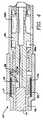
- Fig. 5 is a side cross sectional view of an alternate embodiment of percussion apparatus including a wrap spring clutch assembly of the present invention;
- Fig. 6 is a side cross sectional view of yet another alternate embodiment of percussion apparatus including a wrap spring clutch assembly of the present invention; and
- Fig 7 is a partial side elevational view of a portion of the
piston 60, including associated grooves, of Fig. 5. - In this disclosure, identical elements in different embodiments will be given identical reference characters.
- In a
percussive apparatus 10, generally, for example a rock drill which can be a down hole or out of the hole variety, it is desired to apply rotary motion to adrill steel 14. A wrapspring clutch assembly 16 accomplishes this transmission of rotary motion (Figs. 1-3). The wrapspring clutch assembly 16 includes afirst hub 18, asecond hub 20 and awrap spring 17. - A
first hub surface 24 is formed on thefirst hub 18 while asecond hub surface 26 is formed on thesecond hub 20. Thefirst hub surface 24 and thesecond hub surface 26 are concentric about animaginary axis 22. - The
wrap spring 17 forms a secure engagement with both thefirst hub surface 24 and thesecond hub surface 26. No portion of thewrap spring 17 is fixedly attached to either thefirst hub surface 24 or thesecond hub surface 26. - When the
first hub 18 is rotated in a firstrotational direction 28 relative to thesecond hub 20, coils of thewrap spring 17 will become more tightly secured to both thefirst hub surface 24 and thesecond hub surface 26. Relative rotation between thefirst hub 18 and thesecond hub 20 will thereby be restricted. - Alternately, when the
first hub 18 rotates in a secondrotational direction 30 relative to thesecond hub 20, the coils of thewrap spring 17 will loosen about thefirst hub 18 and thesecond hub 20. This looseness will permit relative rotation between thefirst hub 18 and thesecond hub 20. - The
first hub surface 24 and thesecond hub surface 26 may form either an outercircumferential surface 32 of thefirst hub 18 and the second hub 20 (see Figs. 1 and 2), or an innercircumferential surface 34 thereof (as illustrate in Fig. 3). In both embodiments, relative rotation between thefirst hub 18 and thesecond hub 20 is restricted in the firstrotational direction 28 while permitted in the secondrotational direction 30. - There are three alternate embodiments of the present invention which transform motion of a driver 12 into indexing of the
drill steel 14 in a single direction. This indexing of the drill steel is desired so that each time the drill steel contacts a working surface, it will be at a different angle and position. - In a first embodiment, illustrated in Fig. 4, a plurality of
plunger rods 36 reciprocally act on opposing sides of aplunger tab 37 affixed to aplunger collar 38. Eachplunger rod 36 is reversibly rotationally actuated by working fluid contained within workingchambers 59a,b. Working fluid is alternately applied to theworking chambers 59a,b to cause reciprocation of the piston 12, as is well known in the art. Any rotary motion of thesecond hub 20 is translated to thedrill steel 14. - Figs. 5 and 7 illustrates a second embodiment of the instant invention. A reciprocating
piston 60 is mounted within thepercussive apparatus 10. One or more axially alignedgrooves 62 extend axially on thepiston 60. Aprotuberance 61 extends from a portion of thepercussive apparatus 10 into the axially alignedgrooves 62. This ensures that thepiston 60 will translate axially with substantially no rotation. - Also formed on the piston is one or more
helical grooves 66. A piston nut orhub 70 is substantially axially fixed with respect to a portion of thepercussive apparatus 10, but is rotatable within thepercussive apparatus 10. Aprojection 72 is formed on thepiston nut 70 and extends into thehelical groove 66. Whenever the piston reciprocates axially within the percussion apparatus, theprojection 72, which engages the helical grooves, will force thepiston nut 70 to oscillate rotationally relative to thepiston 60. Note that thepiston 60 in the Fig. 4 embodiment does not containgrooves - The piston hub or
nut 70 is formed with apiston hub surface 74. Achuck 76 is disposed adjacent to thepiston nut 70. Achuck hub surface 78 is formed on thechuck 76. Thechuck hub surface 78 is coaxial with the pistonnut hub surface 74. In this manner, thewrap spring 17 extends between, in matingly contact with, thechuck hub surface 78 and thepiston hub surface 74. The wrap spring interacts with the twohub surfaces - In this manner, axial reciprocation of the
piston 60 will result in rotary reciprocation of thepiston nut 70, which thewrap spring assembly 16 will translate into unidirectional rotational indexing of the chuck. Thedrill steel 14, as described above, is substantially rotationally fixed relative to thechuck 76. However, longitudinal displacement of the drill steel within the chuck is permitted. - During the reciprocation of the piston within the
percussive apparatus 10, the piston will contact the drill steel which is only permitted to be displaced a small axial distance. This contact, and the resultant displacement of the drill steel, results in the impact type motion of the drill steel. - In the two embodiments described above, a bi-directional rotational oscillation upstream of the
wrap spring 17 is translated into a unidirectional indexing downstream of the wrap spring. It should be understood that the wrapspring clutch assembly 16 of the present invention may be used to translate oscillatory motion produced by any well known type device in percussive apparatus applications into uni-directional indexing motion. - In yet another embodiment of the present invention illustrated in Fig. 6, the wrap spring
clutch assembly 16 includes astationary hub 80 which is affixed to abackhead 82 of thepercussion apparatus 10 and a riflebar hub portion 86. Thestationary hub 80 has a firststationary hub surface 85 formed thereon, and the riflebar hub portion 86 has asecond hub surface 88 formed thereon. The wrap spring extends between thefirst hub surface 85 and thesecond hub portion 88, and performs as previously described in this disclosure. - The rifle
bar hub portion 86 includes a substantiallycylindrical portion 89 withhelical grooves 90 formed therein. Apiston 94 is free to rotate except for any limiting contact with the riflebar hub portion 86. One ormore riders 98, which are formed on an internal surface of thepiston 94, ride in thehelical grooves 90 of the riflebar hub portion 89. - The
piston 94 is free to rotate about its axial length within thepercussive apparatus 10. As thepiston 94 travels upwardly, thewrap spring 17 will be tightened around thesecond hub surface 88 and relative rotation between thestationary hub 80 and the riflebar hub portion 86 will be restricted. Therefore, each time the piston 92 travels towards thebackhead 82, the piston will follow thehelical grooves 90. - As the
piston 94 travels away from thebackhead 82, theriders 98 will exert a force against the helical grooves 92, which will act to loosen thewrap spring 17. Relative rotation will thereby be permitted between thestationary hub 80 and the riflebar hub portion 86. - Axially aligned
grooves 104 are formed on an external surface of thepiston 94. Achuck 106, formed fromchuck elements piston 94, and one ormore splines 108 are formed on an internal circumference of thechuck 106. Relative rotation is thereby restricted while longitudinal displacement is permitted, between thepiston 94 and thechuck 106. - The
chuck 106 is formed to encase thedrill steel 14 wherein substantially any rotation applied to the piston is transmitted to thedrill steel 14.
Claims (10)
- A clutch assembly (16) for transmitting rotary motion in a percussive apparatus (10) to a drill steel (14), the clutch assembly comprising a first hub (18) having a first cylindrical surface (24) formed thereon; a second hub (20), substantially rotatably coupled to the drill steel, the second hub having a second cylindrical surface (26) formed thereon, the second cylindrical surface (26) being coaxial with the first cylindrical surface (24); and a wrap spring (17) in engagement with a portion of both the first cylindrical surface (24) and the second cylindrical surface (26), wherein relative rotary motion between the first hub (18) and the second hub (20) is permitted in a first direction and restricted in a second direction, characterised in that a reciprocating piston (12, 60) constituting an impact driving member is provided, said piston being connected to said first hub (18) whereby an axial reciprocating motion of said piston (12,60) moves said first hub (18) in an oscillatory rotary motion to loosen and tighten said wrap spring (17) resulting in relative motion between said first and second hubs (18,20).
- An assembly according to claim 1, wherein the first cylindrical surface (24) and second cylindrical surface (26) are formed on the interior of the first hub (18) and second hub (20), respectively.
- An assembly according to claim 1, wherein the first cylindrical surface and second cylindrical surface are formed on the exterior of the first hub and second hub, respectively.
- An assembly according to claim 1, 2 or 3, wherein the first hub is a driver hub and the second hub is a driven hub.
- An assembly according to any one of the preceding claims, wherein plunger rods (36) are connected to the first hub.
- An assembly according to any one of claims 1 to 4, wherein a rifle bar (86) is connected to the second hub.
- An assembly according to any one of the preceding claims, wherein said second hub is rotatably coupled to said drill steelvia a chuck (106) and there being connector means (108) for substantially limiting relative rotation between the second hub and the drill steel, while permitting longitudinal displacement therebetween.
- An assembly according to any one of the preceding claims, wherein a radius of the first cylindrical surface is substantially equal to a radius of the second cylindrical surface.
- A percussive apparatus (10) incorporating a clutch assembly (16) according to any one of the preceding claims.
- An apparatus according to claim 9, wherein the first hub is rotatably fixed to a housing of the percussive apparatus.
Applications Claiming Priority (3)
| Application Number | Priority Date | Filing Date | Title |
|---|---|---|---|
| US687333 | 1991-04-18 | ||
| US07/687,333US5139093A (en) | 1991-04-18 | 1991-04-18 | Wrap spring clutch for percussive apparatus |
| PCT/US1992/003157WO1992018784A1 (en) | 1991-04-18 | 1992-04-16 | Wrap spring clutch for percussive apparatus |
Publications (2)
| Publication Number | Publication Date |
|---|---|
| EP0580779A1 EP0580779A1 (en) | 1994-02-02 |
| EP0580779B1true EP0580779B1 (en) | 1995-03-01 |
Family
ID=24760040
Family Applications (1)
| Application Number | Title | Priority Date | Filing Date |
|---|---|---|---|
| EP92911809AExpired - LifetimeEP0580779B1 (en) | 1991-04-18 | 1992-04-16 | Wrap spring clutch for percussive apparatus |
Country Status (12)
| Country | Link |
|---|---|
| US (1) | US5139093A (en) |
| EP (1) | EP0580779B1 (en) |
| JP (1) | JPH08506644A (en) |
| KR (1) | KR100234512B1 (en) |
| CN (1) | CN1071430C (en) |
| AU (1) | AU651221B2 (en) |
| BR (1) | BR9205909A (en) |
| CA (1) | CA2105080A1 (en) |
| DE (1) | DE69201560T2 (en) |
| ES (1) | ES2068717T3 (en) |
| WO (1) | WO1992018784A1 (en) |
| ZA (1) | ZA922561B (en) |
Families Citing this family (15)
| Publication number | Priority date | Publication date | Assignee | Title |
|---|---|---|---|---|
| USRE36848E (en)* | 1992-07-17 | 2000-09-05 | Smith International, Inc. | Air percussion drilling assembly |
| US5325950A (en)* | 1992-08-31 | 1994-07-05 | Ingersoll-Rand Company | Lubricant remover for a wrap spring clutch |
| US5305835A (en)* | 1992-09-23 | 1994-04-26 | Ingersoll-Rand Company | Nonrotary piston for jackhammer and removable splined nut therefor |
| USD355355S (en) | 1992-10-09 | 1995-02-14 | Ingersoll-Rand Company | External surface of a splined nut |
| DE4315682A1 (en)* | 1993-05-05 | 1994-11-10 | Harald Kuehnemann | Operating principle of a frictional freewheeling clutch |
| JP3284759B2 (en)* | 1994-06-09 | 2002-05-20 | 日立工機株式会社 | Impact driver |
| US5941360A (en)* | 1996-11-21 | 1999-08-24 | Snap-On Technologies, Inc. | Impulse wrench with wrap spring clutch assembly |
| GB2323900A (en)* | 1997-02-04 | 1998-10-07 | Thomas Wilson Ramsay | A mechanical seal having coiled spring drive means |
| DE19814713A1 (en)* | 1998-04-02 | 1999-10-07 | Geiger Gerhard Gmbh & Co | Bicycle freewheel mechanism including corrugated shaft with torsion coil- spring |
| EP2127823B1 (en)* | 2008-05-27 | 2014-05-07 | Hitachi Koki CO., LTD. | Spring clutch mechanism in screw driver |
| US8397839B2 (en)* | 2008-06-30 | 2013-03-19 | Center Rock Inc. | Self-indexing down-the-hole drill |
| WO2012048131A2 (en)* | 2010-10-06 | 2012-04-12 | Simpirica Spine, Inc. | Device and accessories for limiting flexion |
| US8695773B2 (en)* | 2010-12-15 | 2014-04-15 | Inertia Dynamics Llc | Wrap spring clutch coupling with forced spring clearance disengagement |
| US10024103B2 (en) | 2015-02-04 | 2018-07-17 | Center Rock Inc. | Down-the-hole drill hammer having a roller ramp clutch |
| CN112211974A (en)* | 2020-09-25 | 2021-01-12 | 兰州万里航空机电有限责任公司 | An aviation electric actuator backstop |
Family Cites Families (24)
| Publication number | Priority date | Publication date | Assignee | Title |
|---|---|---|---|---|
| US1791034A (en)* | 1931-02-03 | Blower v-alve bob book drills | ||
| US390029A (en)* | 1888-09-25 | Lin ryder | ||
| USRE25229E (en)* | 1962-08-21 | Spring clutch mechanisms | ||
| GB168984A (en)* | 1920-06-10 | 1921-09-12 | Carl Schurmann | Ratchet coupling |
| US1789117A (en)* | 1928-04-11 | 1931-01-13 | Ingersoll Rand Co | Rock drill |
| US1953370A (en)* | 1931-01-07 | 1934-04-03 | Lgs Devices Corp | Spring clutch |
| US1934252A (en)* | 1931-02-02 | 1933-11-07 | Black & Decker Mfg Co | Bit rotating device for reciprocating tools |
| US2566539A (en)* | 1946-07-22 | 1951-09-04 | Company Fletcher Trust | Spring type clutch |
| US2643749A (en)* | 1948-12-31 | 1953-06-30 | Marquette Metal Products Co | Spring type clutch |
| US2700373A (en)* | 1953-04-14 | 1955-01-25 | Westinghouse Air Brake Co | Rotation device for rock drills |
| US2910046A (en)* | 1957-10-07 | 1959-10-27 | Chicago Pneumatic Tool Co | Rifle nut retainer for rock drill |
| US3044448A (en)* | 1959-04-06 | 1962-07-17 | Joy Mfg Co | Dual rotation for rock drills |
| US2979925A (en)* | 1959-04-30 | 1961-04-18 | Curtiss Wright Corp | Flexible shaft couplings |
| US3166131A (en)* | 1962-08-06 | 1965-01-19 | Ingersoll Rand Co | Rotary percussive rock drill having counter rotation means |
| US3370680A (en)* | 1966-03-03 | 1968-02-27 | Ingersoll Rand Co | Overload released coil clutch |
| DE1483854A1 (en)* | 1966-12-28 | 1970-03-19 | Metabowerke Kg | Hammer drill |
| US3476192A (en)* | 1967-10-09 | 1969-11-04 | Ingersoll Rand Co | Clutch for rotary hammer |
| US4270637A (en)* | 1979-02-26 | 1981-06-02 | Marquette Metal Products | Adjustable spring clutch |
| US4235133A (en)* | 1979-07-11 | 1980-11-25 | Ignacio Acevedo | Torque-applying freely-reversible tool and drive-handle coupling |
| US4341293A (en)* | 1980-11-21 | 1982-07-27 | Ignacio Acevedo | Torque-applying, freely-reversible tool and drive-handle coupling with direction of torque-application selection |
| US4427100A (en)* | 1982-03-15 | 1984-01-24 | General Clutch Corp. | Reversible tool handle |
| DE3731244A1 (en)* | 1987-09-17 | 1989-03-30 | Bosch Gmbh Robert | Hand-held power tool |
| DE3802740A1 (en)* | 1988-01-30 | 1989-08-03 | Hilti Ag | MOTORIZED HAND DEVICE |
| DE4036912A1 (en)* | 1990-11-20 | 1992-05-21 | Bosch Gmbh Robert | HAND MACHINE TOOL |
- 1991
- 1991-04-18USUS07/687,333patent/US5139093A/ennot_activeExpired - Fee Related
- 1992
- 1992-04-08ZAZA922561Apatent/ZA922561B/enunknown
- 1992-04-16WOPCT/US1992/003157patent/WO1992018784A1/enactiveIP Right Grant
- 1992-04-16KRKR1019930703154Apatent/KR100234512B1/ennot_activeExpired - Fee Related
- 1992-04-16BRBR9205909Apatent/BR9205909A/ennot_activeIP Right Cessation
- 1992-04-16JPJP4510896Apatent/JPH08506644A/enactivePending
- 1992-04-16CNCN92102844Apatent/CN1071430C/ennot_activeExpired - Fee Related
- 1992-04-16EPEP92911809Apatent/EP0580779B1/ennot_activeExpired - Lifetime
- 1992-04-16AUAU19039/92Apatent/AU651221B2/ennot_activeCeased
- 1992-04-16CACA002105080Apatent/CA2105080A1/ennot_activeAbandoned
- 1992-04-16DEDE69201560Tpatent/DE69201560T2/ennot_activeExpired - Fee Related
- 1992-04-16ESES92911809Tpatent/ES2068717T3/ennot_activeExpired - Lifetime
Also Published As
| Publication number | Publication date |
|---|---|
| EP0580779A1 (en) | 1994-02-02 |
| ES2068717T3 (en) | 1995-04-16 |
| CN1065914A (en) | 1992-11-04 |
| ZA922561B (en) | 1992-12-30 |
| AU651221B2 (en) | 1994-07-14 |
| DE69201560D1 (en) | 1995-04-06 |
| WO1992018784A1 (en) | 1992-10-29 |
| CN1071430C (en) | 2001-09-19 |
| KR100234512B1 (en) | 1999-12-15 |
| CA2105080A1 (en) | 1992-10-19 |
| DE69201560T2 (en) | 1995-08-03 |
| AU1903992A (en) | 1992-11-17 |
| US5139093A (en) | 1992-08-18 |
| JPH08506644A (en) | 1996-07-16 |
| BR9205909A (en) | 1994-10-11 |
Similar Documents
| Publication | Publication Date | Title |
|---|---|---|
| EP0580779B1 (en) | Wrap spring clutch for percussive apparatus | |
| US3533479A (en) | Impact mechanism with improved hammer and hammer frame assembly therefor | |
| US3866692A (en) | Power tools | |
| US4280359A (en) | Rotary cam drive for impact tool | |
| US5678641A (en) | Drilling and chipping tool | |
| US7059425B2 (en) | Reciprocating power tool | |
| US3161241A (en) | Rotary power hammer | |
| JPS6119395B2 (en) | ||
| GB1438516A (en) | Manual drill hammer machine memory | |
| US3931744A (en) | Hammer-drill | |
| US5305835A (en) | Nonrotary piston for jackhammer and removable splined nut therefor | |
| GB2418634A (en) | Power tool comprising a drive that can be switched over between drilling, percussion drilling and chiselling operating modes | |
| US4825961A (en) | Drilling device | |
| US4669551A (en) | Electropneumatic hammer drill | |
| US5191946A (en) | Wrap spring clutch for percussive apparatus | |
| JP2918057B2 (en) | Drill hammer | |
| US5325950A (en) | Lubricant remover for a wrap spring clutch | |
| US4319646A (en) | Rotary tool drive system for a jack hammer | |
| RU2000112966A (en) | SHOCK AND ROTARY MACHINE | |
| US4557338A (en) | Tool, particularly a boring tool | |
| RU2055183C1 (en) | Perforator | |
| GB2285007A (en) | Hammer drill | |
| DE3215198C2 (en) | ||
| SU1218097A1 (en) | Perforator drill | |
| JPH02212006A (en) | Drilling machine |
Legal Events
| Date | Code | Title | Description |
|---|---|---|---|
| PUAI | Public reference made under article 153(3) epc to a published international application that has entered the european phase | Free format text:ORIGINAL CODE: 0009012 | |
| 17P | Request for examination filed | Effective date:19931004 | |
| AK | Designated contracting states | Kind code of ref document:A1 Designated state(s):DE ES FR GB IT SE | |
| 17Q | First examination report despatched | Effective date:19940630 | |
| GRAA | (expected) grant | Free format text:ORIGINAL CODE: 0009210 | |
| AK | Designated contracting states | Kind code of ref document:B1 Designated state(s):DE ES FR GB IT SE | |
| ITF | It: translation for a ep patent filed | ||
| REF | Corresponds to: | Ref document number:69201560 Country of ref document:DE Date of ref document:19950406 | |
| REG | Reference to a national code | Ref country code:ES Ref legal event code:FG2A Ref document number:2068717 Country of ref document:ES Kind code of ref document:T3 | |
| ET | Fr: translation filed | ||
| PLBE | No opposition filed within time limit | Free format text:ORIGINAL CODE: 0009261 | |
| STAA | Information on the status of an ep patent application or granted ep patent | Free format text:STATUS: NO OPPOSITION FILED WITHIN TIME LIMIT | |
| 26N | No opposition filed | ||
| PGFP | Annual fee paid to national office [announced via postgrant information from national office to epo] | Ref country code:FR Payment date:20010330 Year of fee payment:10 | |
| PGFP | Annual fee paid to national office [announced via postgrant information from national office to epo] | Ref country code:SE Payment date:20010402 Year of fee payment:10 Ref country code:DE Payment date:20010402 Year of fee payment:10 | |
| PGFP | Annual fee paid to national office [announced via postgrant information from national office to epo] | Ref country code:GB Payment date:20010403 Year of fee payment:10 | |
| PGFP | Annual fee paid to national office [announced via postgrant information from national office to epo] | Ref country code:ES Payment date:20010511 Year of fee payment:10 | |
| REG | Reference to a national code | Ref country code:GB Ref legal event code:IF02 | |
| PG25 | Lapsed in a contracting state [announced via postgrant information from national office to epo] | Ref country code:GB Free format text:LAPSE BECAUSE OF NON-PAYMENT OF DUE FEES Effective date:20020416 | |
| PG25 | Lapsed in a contracting state [announced via postgrant information from national office to epo] | Ref country code:SE Free format text:LAPSE BECAUSE OF NON-PAYMENT OF DUE FEES Effective date:20020417 Ref country code:ES Free format text:LAPSE BECAUSE OF NON-PAYMENT OF DUE FEES Effective date:20020417 | |
| PG25 | Lapsed in a contracting state [announced via postgrant information from national office to epo] | Ref country code:DE Free format text:LAPSE BECAUSE OF NON-PAYMENT OF DUE FEES Effective date:20021101 | |
| EUG | Se: european patent has lapsed | Ref document number:92911809.9 | |
| GBPC | Gb: european patent ceased through non-payment of renewal fee | Effective date:20020416 | |
| PG25 | Lapsed in a contracting state [announced via postgrant information from national office to epo] | Ref country code:FR Free format text:LAPSE BECAUSE OF NON-PAYMENT OF DUE FEES Effective date:20021231 | |
| REG | Reference to a national code | Ref country code:FR Ref legal event code:ST | |
| REG | Reference to a national code | Ref country code:ES Ref legal event code:FD2A Effective date:20030514 | |
| PG25 | Lapsed in a contracting state [announced via postgrant information from national office to epo] | Ref country code:IT Free format text:LAPSE BECAUSE OF NON-PAYMENT OF DUE FEES Effective date:20050416 |