EP0579012B1 - Apparatus and methods for applying discrete coatings - Google Patents
Apparatus and methods for applying discrete coatingsDownload PDFInfo
- Publication number
- EP0579012B1 EP0579012B1EP93110164AEP93110164AEP0579012B1EP 0579012 B1EP0579012 B1EP 0579012B1EP 93110164 AEP93110164 AEP 93110164AEP 93110164 AEP93110164 AEP 93110164AEP 0579012 B1EP0579012 B1EP 0579012B1
- Authority
- EP
- European Patent Office
- Prior art keywords
- air
- coating material
- slot
- extrusion
- coating
- Prior art date
- Legal status (The legal status is an assumption and is not a legal conclusion. Google has not performed a legal analysis and makes no representation as to the accuracy of the status listed.)
- Expired - Lifetime
Links
- 238000000576coating methodMethods0.000titleclaimsdescription100
- 238000000034methodMethods0.000titleclaimsdescription19
- 239000011248coating agentSubstances0.000claimsdescription77
- 239000000463materialSubstances0.000claimsdescription58
- 238000001125extrusionMethods0.000claimsdescription36
- 239000000758substrateSubstances0.000claimsdescription32
- 239000000853adhesiveSubstances0.000claimsdescription29
- 230000001070adhesive effectEffects0.000claimsdescription29
- 238000000151depositionMethods0.000claimsdescription8
- 230000002745absorbentEffects0.000claimsdescription6
- 239000002250absorbentSubstances0.000claimsdescription6
- 230000000977initiatory effectEffects0.000claims1
- 239000012943hotmeltSubstances0.000description21
- 239000004831Hot glueSubstances0.000description15
- 230000008569processEffects0.000description8
- 238000003475laminationMethods0.000description7
- 230000008021depositionEffects0.000description4
- 238000004519manufacturing processMethods0.000description4
- 230000003247decreasing effectEffects0.000description3
- 239000003292glueSubstances0.000description3
- 238000007664blowingMethods0.000description2
- 239000000835fiberSubstances0.000description2
- 239000007921spraySubstances0.000description2
- 230000008719thickeningEffects0.000description2
- 230000005540biological transmissionEffects0.000description1
- 230000008859changeEffects0.000description1
- 230000001934delayEffects0.000description1
- 230000008018meltingEffects0.000description1
- 238000002844meltingMethods0.000description1
- 230000004048modificationEffects0.000description1
- 238000012986modificationMethods0.000description1
- 239000003973paintSubstances0.000description1
- 239000002245particleSubstances0.000description1
- 238000005086pumpingMethods0.000description1
- 239000007787solidSubstances0.000description1
- 238000005507sprayingMethods0.000description1
- 239000012815thermoplastic materialSubstances0.000description1
Images


Classifications
- B—PERFORMING OPERATIONS; TRANSPORTING
- B05—SPRAYING OR ATOMISING IN GENERAL; APPLYING FLUENT MATERIALS TO SURFACES, IN GENERAL
- B05C—APPARATUS FOR APPLYING FLUENT MATERIALS TO SURFACES, IN GENERAL
- B05C5/00—Apparatus in which liquid or other fluent material is projected, poured or allowed to flow on to the surface of the work
- B05C5/02—Apparatus in which liquid or other fluent material is projected, poured or allowed to flow on to the surface of the work the liquid or other fluent material being discharged through an outlet orifice by pressure, e.g. from an outlet device in contact or almost in contact, with the work
- B05C5/027—Coating heads with several outlets, e.g. aligned transversally to the moving direction of a web to be coated
- B05C5/0275—Coating heads with several outlets, e.g. aligned transversally to the moving direction of a web to be coated flow controlled, e.g. by a valve
- B—PERFORMING OPERATIONS; TRANSPORTING
- B05—SPRAYING OR ATOMISING IN GENERAL; APPLYING FLUENT MATERIALS TO SURFACES, IN GENERAL
- B05B—SPRAYING APPARATUS; ATOMISING APPARATUS; NOZZLES
- B05B7/00—Spraying apparatus for discharge of liquids or other fluent materials from two or more sources, e.g. of liquid and air, of powder and gas
- B05B7/02—Spray pistols; Apparatus for discharge
- B05B7/08—Spray pistols; Apparatus for discharge with separate outlet orifices, e.g. to form parallel jets, i.e. the axis of the jets being parallel, to form intersecting jets, i.e. the axis of the jets converging but not necessarily intersecting at a point
- B05B7/0807—Spray pistols; Apparatus for discharge with separate outlet orifices, e.g. to form parallel jets, i.e. the axis of the jets being parallel, to form intersecting jets, i.e. the axis of the jets converging but not necessarily intersecting at a point to form intersecting jets
- B05B7/0861—Spray pistols; Apparatus for discharge with separate outlet orifices, e.g. to form parallel jets, i.e. the axis of the jets being parallel, to form intersecting jets, i.e. the axis of the jets converging but not necessarily intersecting at a point to form intersecting jets with one single jet constituted by a liquid or a mixture containing a liquid and several gas jets
- B—PERFORMING OPERATIONS; TRANSPORTING
- B05—SPRAYING OR ATOMISING IN GENERAL; APPLYING FLUENT MATERIALS TO SURFACES, IN GENERAL
- B05C—APPARATUS FOR APPLYING FLUENT MATERIALS TO SURFACES, IN GENERAL
- B05C5/00—Apparatus in which liquid or other fluent material is projected, poured or allowed to flow on to the surface of the work
- B05C5/02—Apparatus in which liquid or other fluent material is projected, poured or allowed to flow on to the surface of the work the liquid or other fluent material being discharged through an outlet orifice by pressure, e.g. from an outlet device in contact or almost in contact, with the work
- B05C5/0254—Coating heads with slot-shaped outlet
- B—PERFORMING OPERATIONS; TRANSPORTING
- B05—SPRAYING OR ATOMISING IN GENERAL; APPLYING FLUENT MATERIALS TO SURFACES, IN GENERAL
- B05C—APPARATUS FOR APPLYING FLUENT MATERIALS TO SURFACES, IN GENERAL
- B05C5/00—Apparatus in which liquid or other fluent material is projected, poured or allowed to flow on to the surface of the work
- B05C5/02—Apparatus in which liquid or other fluent material is projected, poured or allowed to flow on to the surface of the work the liquid or other fluent material being discharged through an outlet orifice by pressure, e.g. from an outlet device in contact or almost in contact, with the work
- B05C5/0225—Apparatus in which liquid or other fluent material is projected, poured or allowed to flow on to the surface of the work the liquid or other fluent material being discharged through an outlet orifice by pressure, e.g. from an outlet device in contact or almost in contact, with the work characterised by flow controlling means, e.g. valves, located proximate the outlet
- B05C5/0237—Fluid actuated valves
- H—ELECTRICITY
- H05—ELECTRIC TECHNIQUES NOT OTHERWISE PROVIDED FOR
- H05K—PRINTED CIRCUITS; CASINGS OR CONSTRUCTIONAL DETAILS OF ELECTRIC APPARATUS; MANUFACTURE OF ASSEMBLAGES OF ELECTRICAL COMPONENTS
- H05K3/00—Apparatus or processes for manufacturing printed circuits
- H05K3/0091—Apparatus for coating printed circuits using liquid non-metallic coating compositions
- Y—GENERAL TAGGING OF NEW TECHNOLOGICAL DEVELOPMENTS; GENERAL TAGGING OF CROSS-SECTIONAL TECHNOLOGIES SPANNING OVER SEVERAL SECTIONS OF THE IPC; TECHNICAL SUBJECTS COVERED BY FORMER USPC CROSS-REFERENCE ART COLLECTIONS [XRACs] AND DIGESTS
- Y10—TECHNICAL SUBJECTS COVERED BY FORMER USPC
- Y10T—TECHNICAL SUBJECTS COVERED BY FORMER US CLASSIFICATION
- Y10T156/00—Adhesive bonding and miscellaneous chemical manufacture
- Y10T156/17—Surface bonding means and/or assemblymeans with work feeding or handling means
- Y10T156/1798—Surface bonding means and/or assemblymeans with work feeding or handling means with liquid adhesive or adhesive activator applying means
Definitions
- This inventionrelates to the application of coatings to substrates and more particularly to the application to substrates of discrete, uniform coatings having sharp, square cut-on and cut-off edges.
- curtain coatersdo not generally provide acceptable cut-on and cut-off performance. Also, they do produce unacceptable neck-in, causing thickening of applied coating at the edges, or "rail roading".
- Contact coaterspresent the inherent disadvantage of wear and substrate index and tension tolerances.
- the spray, fine line and spiral pattern applicatorsdo not generally produce highly defined square edge cut-on and cut-off coating edges in a uniform broad coating, as are desired in a number of applications.
- melt-blowing processWhile not related to lamination applications generally, another technique used for producing fibers and non-woven webs is known as a melt-blowing process.
- a melt-blowing processis described in U.S. Patent No. 4,720,252.
- hot melt thermoplastic materialis extruded from a continuous slot opening and air is blown onto the extruding material from both sides of the slot opening to produce the desired webs.
- Such processesare used for web production, and do not generally concern themselves with intermittent operation to produce discrete coatings, nor with extruding adhesives for lamination applications.
- Japanese patent application JP-4066158describes an apparatus for producing a coating for the application to a substrate comprising a slot nozzle having an elongated slot outlet through which a coating material can be extruded.
- This documentalso described a method for applying a discrete coating to a substrate by extruding coating material from an elongated slot nozzle.
- This contact-type coaterspresent the disadvantages of friction and wear. Indexing of the substrate can be influenced by friction between the contact coater and the substrate. Also, the contact coater does not allow to influence the coating material before the deposition onto the substrate.
- the air start-up on both sidesprecedes extrusion start-up and continues until after the extrusion is stopped.
- the air on one side of the nozzleis started before extrusion is started and terminates before extrusion is stopped while air on another side of the nozzle starts at or after extrusion start-up and continues until after extrusion stops.
- Continuation of air flow after extrusion stoppagecan draw coating material remaining at or in the nozzle into the air stream and onto a substrate, causing stringing. Accordingly, the delay of air stoppage after extrusion stoppage is predetermined to produce good sharp, square coating pattern cut-off, but not so long as to draw remaining glue at the nozzle therefrom so as to cause stringing.
- the air start-up and stop delaysare preferably on the order of micro-seconds.
- the inventionproduces uniform, wide or broad coatings with no significant edge thickening, having sharp side edges and sharp, square, leading and trailing edges coordinated with a predetermined underlying substrate area and applied in a non-contacting application process.
- such coatingsare either open, fibrous or porous coatings, or, on the other hand, are solid films.
- coatingscan be formed from glue or adhesive materials, such as hot melt adhesives, or from cold glues, paints, or other materials of adhesive or non-adhesive nature. The invention will be described herein in terms of its use with hot melt adhesive.
- Fig. 1illustrates various features of a die means 30 and air and hot melt adhesive controls according to the invention.
- the die means 30comprises two die halves 31, 32, and two air blocks 33, 34.
- Each die block 31, 32includes a downwardly depending projection 35, 36.
- the die halves 31, 32define between them an extrusion slot 37.
- Slot 37is defined by the face 38 of the die half 31 and the face 39 of the die half 32. Face 38 is juxtaposed with respect to the face 39, as shown.
- the extrusion slot 37terminates at an elongated slot or extrusion outlet 40.
- the air blocksextend below the outlet 40 to provide a degree of protection from mechanical damage.
- Die half 32includes a hot melt passageway 41 for receiving hot melt adhesive and conducting the hot melt adhesive to a "coat hanger" portion 42 of the die half 32, details of which are perhaps better seen in Fig. 4.
- a slotted or segmented shim 45is located between the juxtaposed surfaces 38 and 39 of the die halves 31 and 32.
- the shim 45has a plurality of elongated projections 46, extending at least proximate to the slot outlet 40, defining between them a plurality of elongated channels or slots 47.
- Each of the projectionshas a downstream tapered end portion 48, having a tip 49 which is just short of, flush with or just outwardly of the lower edge 50 of the shim, and just short of, flush with or just outwardly of the elongated slot nozzle extrusion outlet 40 (Fig. 1).
- Fig. 1only the top portion 51 of the shim 45 is shown, for the purpose of clarity.
- an open shimcan be used. Such an open shim is depicted in Fig 6A at 45a. This shim has an open area 45b, with no projection 46.
- the tapered end portion 48 or tips 49can extend beyond outlet 40, preferably two or three thousandths of an inch.
- each of the upper die halves 31, 32is provided with an air passageway 55, 56, extending from an upper surface of the die to a lower respective surface 57, 58.
- Each die half 31, 32also includes an inclined surface 59, 60, depending from the surfaces 57 and 58, respectively.
- the inclined surfaces 59 and 60define one part of an air passage, or air slot 61 and 62, as will be described.
- each of theminclude an inclined surface 63 and 64, respectively, which define the other side of the air slots 61 and 62 with the juxtaposed respective surfaces 59, 60, all as shown in Fig. 1.
- Each of the air blocks 33 and 34include an upper surface 65, 66 juxtaposed to the respective lower surfaces 57 and 58 of the die halves 31, 32.
- An elongated air plenum 67, 68is formed in each of the air blocks 33, 34.
- the plenums 67, 68are also seen in Fig. 4.
- Respective air passages 69 and 70are formed in the respective air blocks 33 and 34 and extend from the respective surfaces 65 and 66 to a lower portion 71, 72 of the respective plenums 67, 68.
- Each of the plenums 67, 68are primarily defined in the air blocks 33 and 34. However, when the die means 30 are assembled, the top area of each of the respective plenums 67, 68 are defined respectively by the lower surfaces 57 and 58 of the die halves 31, 32.
- aircan be introduced to passageway 56 in the die half 32 and from there it can move into the air passageway 70 and into the lower portion of the plenum 68. From the plenum 68, pressurized air is directed through the air passage 74 into the air slot 62 of the air block 34.
- a controller 75is operationally connected to valves V-1 and V-2, as shown, for controlling the introduction of heated, pressurized air to the passages 55 and 56, respectively, in order to pressurize those passages and the downstream air passages as previously described, with air.
- the controller 75is operationally interconnected to a hot melt control valve 76 for controlling the supply of coating material, such as hot melt adhesive, to the hot melt adhesive passage 41 and to the internal coat hanger area 42 of the die means 30.
- coating materialsuch as hot melt adhesive
- the PC-10 pattern control 75is operational to initiate and to stop the generation of air into passages 55 and 56, either simultaneously or independently, and also to initiate and to stop the hot melt flowing through valve 76 so as to intermittently provide coating material to the passageway 41 independently and at pre-selected times with respect to the provision of pressurized heated air to the passages 55 and 56, all in a manner as will be described.
- the air slots 61 and 62are oriented on an angle with respect to the elongation of the extrusion slot 37. Accordingly, when coating material is extruded through the slot 37 and outwardly of the extrusion outlet 40, air moving through the air slots 61 and 62 is impinged on the material before that material engages or is deposited on an underlying substrate which is presented for coating.
- Figs. 2 and 3there is shown more of the overall extrusion apparatus according to the invention.
- the die means 30is interconnected with air valves V-1, V-2 and hot melt valve 76, each of which is interconnected with an extrusion body 80 which operationally interconnects the air and hot melt valves with the die means 30.
- valve V-2For clarity, a portion or the air valve V-2 is shown in partial cross section in Fig 2. Since the valves V-1 and V-2 are identical, only valve V-2 will be described.
- Such air valvesare manufactured and distributed by Nordson Corporation through Nordson Engineering, Luneburg, Germany, under part no. 265701. Any other suitable air valve can be used.
- Valve V-2comprises a valve body 82 defining a valve chamber 83 and a control chamber 84, the two chambers being separated by the diaphragm 85.
- An extension 86 having a bore 87 extending therethroughdepends from the valve body 82 and extends into the bore 88 of extrusion body 80 to form an annular chamber 89 therewith.
- Chamber 89is interconnected with an annular passageway 90 in the valve body 82, which interconnects with the chamber 83.
- An annular chamber 91is also defined in the valve body 82 and interconnects with the chamber 83.
- the air valve V-1is operable to selectively supply air to the air passage 93 in the extrusion body 80 and from there to the air passage 55 in the upper die half 31. Air moves through that passageway 55 into the plenum 67 and from there to the air slot 61.
- the hot melt valve 76can be any suitable hot melt valve which can be selectively controlled to initiate and to cut off the flow of coating material, such as hot melt adhesive, to the die means 30.
- One such suitable valveis balanced valve model no. EP51 produced by Nordson Corporation of Westlake, Ohio. Such valve minimizes significant change in pressures when the valve is switched between its opened and closed positions.
- the valve 76has a stem 96 seated over a port 97. When control air is supplied to an inlet 98, the stem 96 is lifted to permit hot melt adhesive in a chamber 99 to flow through the port 97 and into the hot melt passageway 41 of the upper die half 32. Hot melt adhesive is introduced into the chamber 99 through hot melt inlet 100.
- a hot melt outlet 101is also interconnected with the chamber 99 to receive pressurized hot melt adhesive when the stem 96 is seated on port 97.
- Any suitable apparatuscan be utilized for melting and pumping hot melt adhesive to the valve 76. Such apparatus is shown diagrammatically at 102. While any suitable apparatus could be utilized, one particular form of apparatus which is suitable is the model HM640 applicator, manufactured by Nordson Corporation of Westlake, Ohio.
- the coating materialmay be precisely delivered to the heads or nozzles by one or more material metering means such as metering gear pumps.
- a single pumpcould feed a manifold for all the heads or nozzles or a separate metering gear pump could be used for each head or nozzle, or for a group of nozzles of less than all nozzles.
- This precise deliverypermits accuracy in the material delivery so that accurate basis weight coatings can be provided for varying substrate speeds, for example. Any suitable form of metering feeds can be utilized.
- Fig. 3illustrates diagrammatically the various control inputs to the valves 76 and V-1.
- the controller 75is interconnected to a control air supply 105 for supplying control air to the valves V-1 and V-2.
- a pressurized air source 106is interconnected to an air heater 107 which supplies process air to the valves V-1 and V-2 for transmission to the respective air slots 61, 62, as described above.
- controller 75is also interconnected to the control air supply for supplying control air through closed and opened solenoid control valves (shown in Fig. 3) to open and close the hot melt valve 76.
- plenums 67 and 68 in the air blocks 33, 34communicate with the lower surfaces 73A and 74A, respectively, of the air passages 73 and 74 as previously described, and air emanating from the upper portion of the plenums 67 and 68 moves through the passageways 73 and 74 and then downwardly through the respective air slots 61, 62.
- coat hanger portion 42 of the upper die half 32and with reference to Fig. 4, it will be appreciated that “coat hanger” dies are known in general. The difference in that structure is that it serves a plurality of die outlets, and not a continuous extrusion slot die as noted herein. While such a die could be used herein, nevertheless, the present die means 30 incorporates a "coat hanger" portion 42 having an arcuate slot or groove of increasingly shallow dimension 110 communicating with an incline surface 111. Surface 111 is inclined such that its lower portion, where it meets bottom surface 112, is closer to the plane of the face 39 than is the upper portion.
- slot 110is of decreasing depth as its distance from port 113 continues until it flows unbroken in surface 111.
- the arcuate slot 110 of decreasing depthis fed by the hot melt port 113, which is interconnected to the hot melt passage 41.
- hot meltwhen hot melt is supplied at pressure to the passage 41, it exudes through the port 113 into the arcuate slot 110 and from there flows over the surface 111 and spreads out throughout the relieved coat hanger shaped portion 42 of the die face 39 and the side of the shim 45 which is juxtaposed to the face 39 of the die half 32.
- the slots 47 of shim 45have upper ends which communicate with the lower portion of the coat hanger die area 42, just above the surface 112 thereof, so that hot melt adhesive or other coating material can flow into the slots 47 and then downwardly to the extrusion outlet 40.
- the coating materialis spread throughout the coat hanger portion 42 and across each of the upper ends of the slots 47 of the shim 45 at significantly equal pressures, so that coating material can move through the extrusion slot 37 within the slots 47 of the shim 45 at relatively equal pressures.
- the width of the slot 47 between projections 46is preferably about twice the thickness of the shim.
- the thickness of one shim 45may be about 0.1 mm (.004") while the slot width, i.e. from one projection 46 across to the next projection 46, is about 0.2 mm (.008").
- the shim thicknessis about 0.2 mm (.008") while the segmented slot width between juxtaposed projections is about 0.4 mm (.016”)
- the overall slot thickness between die faces 38, 39can be doubled while the die still produces the same basis weight coating as a prior slot die where the die slot is not segmented, as in this invention.
- the present inventioncan obtain the same basis weight coating with a slot thickness of 0.1 mm (.004"), or doubled.
- the slot die according to the inventioncould pass a potentially clogging particle of 0.08 mm (.003") while the prior continuous slot die would not (for the same basis weight coating to be produced).
- the ratio of the shim thickness to the shim slot widthis preferably about 2 to 1, this ratio can be varied to produce varying coating thicknesses.
- width and thickness parameters of the shims 45, 45a and their componentscan widely vary.
- the parametersmay vary due to the basis weight of coating per square meter desired, the cohesiveness desired, the coating material viscosity or other factors.
- the surface 112 from face 39 back to surface 111is about 0.5 mm (.020") wide.
- the tops of slots 47are about 1.27 mm (.050") when the shim is operably disposed between faces 38, 39.
- the groove 110 at its deepest depth from face 39is about 3.175 mm (.125") from face 39.
- the surface 111 at its top areais about 1.587 mm (1/16") deep from face 111 and about 0.5 mm (.020”) back from surface 39 at its bottom.
- the coat hanger width across face 39is about 38 mm.
- the overall die headcould be expanded in length with, for example, open areas in the shim so that a wide, unbroken coating of greater than 38 mm could be obtained.
- several nozzles, each about 38 mm widecould be closely spaced in adjacent fashion with very narrow lands therebetween to produce a wide pervious or impervious film as disclosed herein.
- the apparatusis capable of impinging hot air from the slots 61 and 62 on each side of the coating material exuding from the extrusion outlet 40.
- the impinging airengages and shreds the energizing expanse of coating material into discrete micro-denier fibers.
- Edge controlis uniform and the density of the pattern can range from 25% open or fibrous to 0% open, i.e. a non-porous film.
- the parametersare selected depending on the application to which the coatings are to be applied.
- the controller 75is operational to start and stop the application of air to the extruded coating material at different times and/or intervals compared to the starting and stopping of the delivery of hot melt adhesive to the extrusion outlet 40.
- the flow of air through the slots 61, 62is started a short time prior to the time when the valve 76 is operated to initiate the delivery of coating material into the slot 37 and out through the outlet 40.
- the airis continued for the coating deposition, shredding or fiberizing the extruding material and carrying it to or spraying it on a substrate.
- the valve 76is first operated to cease the extrusion of coating material through the outlet 40.
- the flow of air through the slot 61 and 62is stopped. While the amount of delay in such an operation will vary, depending upon the properties of the hot melt, such time period generally will preferably be on the order of micro seconds.
- One examplewould be, for example, 1700 micro seconds between the start up of the air and the start up of the extrusion of the hot melt material, and 2100 micro seconds between the stopping of the hot melt material and the stopping of the air. Continuation of the air flow much beyond this time might serve to pull off remaining hot melt adhesive at the extrusion outlet and cause stringing of the deposited coating.
- the inventioncontemplates the selective applications of air flow through either slot 61 or 62 individually or together during the deposition period, particularly to more accurately define the initial and ending contact position of the deposited coating on the substrate.
- One such mode of operationis illustrated in Fig. 5, where the apparatus is utilized, for example, to apply a discrete coating to the spine of a book so that a cover can be applied or laminated thereto.
- a book having a spine with no adhesive thereonis shown at the left hand side of the figure at position B-1.
- air flowhas been initiated through slot 61 but there is no coating material being extruded through the slot 37 and no air flow has started through the air slot 62.
- the hot melt flowhas started and that it is impinged by air flowing through slot 61. Since the air flowing through slot 61 moves downwardly in a general right to left direction as shown in Fig. 5, it will be appreciated that the coating material does not string down the side of the book pages but is applied directly to the edge of the spine of the book with no stringing.
- the lag airis started first and stopped first and the lead air, that is, with respect to the machine direction of the application as shown in Fig. 5, is started after the extrusion of the coating material and stopped after the coating material extrusion has ceased.
- the air angling onto the coating materialdoes not blow it in strings over the edges of the book, as would be undesirable and yet the cut-off and cut-on edges of the coating material are maintained in sharp, square fashion on the spine of the book.
- the inventionis useful in many applications.
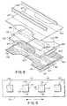
- the inventionis useful in applying adhesive to components of a consumable product, such as a disposable diaper made up from impervious synthetic films, non-woven absorbent material or "fluff" and elastic for waist and leg area gatherings.
- a disposable diaper 150is illustrated in exploded view, showing its typical components.
- the diaperincludes an impervious outer sheet 151, an absorbent non-woven or "fluff” layer 152, a “fluff” tissue cover 153, a pervious cover sheet 154, elastic waist bands 155, elongated elastic strands 156, 157, and fastening tapes 158.
- Lines of adhesiveare applied by the apparatus described herein, in either fibrous or impervious form, to hold the diaper components together.
- lamination of the outer sheet 151 to the tissue covered "fluff” 152is accomplished by application of adhesive stripes or bands at 160, 161 and 162.
- Adhesive bands 163are applied to stabilize the "fluff” 152 to tissue 153.
- Adhesive bands 164are applied for securing elastic waist bands to the diaper 150.
- Adhesive bands 165are applied over elastic strands in the leg and interior areas.
- Adhesive bands 166are applied to adhere the non-woven tissue covered "fluff” 152 to the cover sheet 154.
- Adhesive bands 167are applied to hold the elastic strands 156 to cover sheet 154 and for end tack at the leg gather area of the diaper.
- the adhesive bands or stripes 160-167are varied in width. They can be applied by apparatus as disclosed herein oriented along a diaper manufacturing line at predetermined positions as necessary, with sharp and square side and leading and trailing edges.
- the inventionis believed useful in many other applications and with a wide range of coating materials of different viscosities, as shown by the following two examples.
- This adhesivehad the following viscosities at the following temperatures:
- Operating temperaturewas at 180 degrees C. With a 0.1 millimeter thick shim in the head, the supply pressure was 20 BAR, the return pressure of the adhesive was 21 BAR, and the air pressure was 1.5 BAR. The air was turned on 2 millimeters of substrate travel before the adhesive and turned off 2 millimeters of substrate travel after the adhesive. Substrate line speed is about 150 meters/minute. This corresponds to the delay times of about 800 micro seconds. At these settings, the cut-on and cut-off were square and sharp and a coating weight was produced of 5 grams per square meter of uniform thickness.
- This adhesivehad the following viscosities:
- Operating temperaturewas 149 °C (300 degrees F).
- Coating weightwas 15 grams per square meter. Cut-on and cut-off were square and sharp with no stringing.
- the hot melt supply pressure and return pressurebe maintained in a relationship, such that the differences of the two pressures are not more than 1 BAR.
- a minimum flow rateis required to produce a uniform pattern with square and sharp cut-ons and cut-offs.
- a minimum flow rateis required to produce a uniform pattern with square and sharp cut-ons and cut-offs.
- a 38 millimeter wide patternit is possible to get down to at least 1 gram per square meter of coating weight at approximately 350 meters per minute of line speed.
- the graph in Fig. 7illustrates coating weights which have been obtained with a 38 millimeter wide pattern deposited on a substrate moving at about from 70 meters per minute to about 350 meters per minute, with the shaded area of the graph (Fig. 7) illustrating the proven operating ranges.
- coatingsare produced in varying weights. Such coatings can be varied from 0% open or impervious to about 25% open or porous.
- the hot meltmight be started at 2 mm of substrate movement after air start up, and the air flow stopped at 5 mm of substrate movement beyond extrusion shut off, for substrate speeds of about 70 meters/minute.
- the particular coating pattern produced by the apparatus and methods described abovecan either be porous or impervious and that the coating patterns are preferably produced in a discrete fashion on discrete substrates, for example, with good, square, sharp cut-on and cut-off and no stringing for the leading or trailing edges of the pattern, while at the same time, the sides of the pattern deposited are also parallel and sharp.
- Fig. 9illustrates the sharp edged, square coating patterns attainable with the invention.
- discrete adhesive coatings 170-173have been applied by the invention to a substrate 174.
- Each discrete coatinghas two sharply defined side edges 175, 176, a sharply defined leading edge 177, and a sharply defined trailing edge 178.
- Sides 175, 176are square to leading and trailing edges 177, 178. There is substantially no stringing.
- the inventionprovides for intermittent non-contact coating operation with sharp, square-edged patterns and no stringing for a variety of applications, including lamination of the substrate to which the patterns are applied to some other substrate or component.
Landscapes
- Coating Apparatus (AREA)
- Application Of Or Painting With Fluid Materials (AREA)
- Absorbent Articles And Supports Therefor (AREA)
- Nozzles (AREA)
- Non-Metallic Protective Coatings For Printed Circuits (AREA)
- Orthopedics, Nursing, And Contraception (AREA)
Description
Claims (10)
- Apparatus for producing a coating for application to a substrate, saidapparatus comprising:a slot nozzle having an elongated slot outlet (40) through which a coating materialcan be extruded;
characterized by at least one air slot (61, 62) proximate said slot outlet (40) forimpinging at least one air stream onto a coating material exuding from said slotoutlet (40) and by means for starting the flow of air prior to extrusionof coating material from said slot outlet (40). - Apparatus as in claim 1 further including means (76) for stopping the flowof air after extrusion of coating material has ceased.
- Apparatus as in claim 2 including at least two air slots (61, 62), one proximateeach side of said slot outlet (40) for impinging air therefrom onto coatingmaterial exuding from said slot outlet (40).
- Apparatus as in claim 3 further including means (75, 105) for delayingimpinging air from one of said air slots (61, 62) until after coating material exudesfrom said slot outlet (40) and for continuing flow of air from said one slot (61) untilafter extrusion of said coating material has ceased.
- Apparatus as in claim 4 further including means (75, 105) for initiating flowof air from the other air slot (62) before coating material is extruded and forceasing flow of air from said other (62) air slot before extrusion of said coatingmaterial ceases.
- Use of an apparatus according to at least one at claims 1 to 5 for adheringtogether components of disposable diapers each having an impervious outer sheet,an absorbent layer and elastic members for waist and leg holes.
- A method for applying a discrete coating to a substrate comprising thesteps of:extruding coating material from an elongated slot nozzle,
characterized by a non-contact coating operation, impinging air at an angle ontoextruding coating material and then depositing extruded coating material onto saidsubstrate, and
by starting and stopping the extrusion of coated material and theflow of impinging air at preselected different times to produce discrete coatingswith even leading and trailing edges. - A method according to claim 7,
characterized by adhering components together and by depositing the extrudedadhesive coating material onto discrete areas of at least one of said componentsfor securing same to another of said components. - A method as claimed in claim 8 wherein said components are elements ofa disposable diaper of the type having an impervious outer coversheet, an internalabsorbent layer, and a elastic strands in at least one of the waistband and leg holeareas, and further characterized by depositing the extruded adhesive coatingmaterial onto discrete areas of said outer coversheet for securing said absorbentlayer thereto.
- A method as claimed in claim 8 wherein said components are elements ofa disposable diaper of the type having an impervious outer coversheet, an internalabsorbent layer, and a elastic strands in at least one of the waistband and leg holeareas, and further
characterized by depositing extruded adhesive coating material onto said elasticstrands to adhere said elastic strands to said outer coversheet.
Applications Claiming Priority (2)
| Application Number | Priority Date | Filing Date | Title |
|---|---|---|---|
| US91078192A | 1992-07-08 | 1992-07-08 | |
| US910781 | 1992-07-08 |
Publications (2)
| Publication Number | Publication Date |
|---|---|
| EP0579012A1 EP0579012A1 (en) | 1994-01-19 |
| EP0579012B1true EP0579012B1 (en) | 1998-04-01 |
Family
ID=25429315
Family Applications (1)
| Application Number | Title | Priority Date | Filing Date |
|---|---|---|---|
| EP93110164AExpired - LifetimeEP0579012B1 (en) | 1992-07-08 | 1993-06-25 | Apparatus and methods for applying discrete coatings |
Country Status (7)
| Country | Link |
|---|---|
| US (3) | US5423935A (en) |
| EP (1) | EP0579012B1 (en) |
| JP (1) | JP2713542B2 (en) |
| AU (1) | AU660262B2 (en) |
| CA (1) | CA2099316A1 (en) |
| DE (1) | DE69317706T2 (en) |
| ES (1) | ES2115700T3 (en) |
Families Citing this family (87)
| Publication number | Priority date | Publication date | Assignee | Title |
|---|---|---|---|---|
| GB9403702D0 (en)* | 1994-02-25 | 1994-04-13 | Flow Research Evaluation Diagn | Improvements relating to spray generators |
| US5458291A (en)* | 1994-03-16 | 1995-10-17 | Nordson Corporation | Fluid applicator with a noncontacting die set |
| US5518762A (en)* | 1994-06-03 | 1996-05-21 | Moore Business Forms, Inc. | Method and apparatus for manufacturing linerless labels |
| GB2290730A (en)* | 1994-06-28 | 1996-01-10 | Redland Technology Ltd | Coating by spraying |
| CA2149700A1 (en)* | 1994-08-12 | 1996-02-13 | Brendon Frank Ribble | Method for applying an elastic member to a moving substrate |
| US7078075B1 (en) | 1995-02-23 | 2006-07-18 | H.B. Fuller Licensing & Financing Inc. | Method for producing a continuous thermoplastic coating and articles constructed therefrom |
| JP3834737B2 (en)* | 1995-05-18 | 2006-10-18 | ノードソン株式会社 | Method for spraying liquid or heated melt |
| US5728219A (en)* | 1995-09-22 | 1998-03-17 | J&M Laboratories, Inc. | Modular die for applying adhesives |
| DE19548607A1 (en)* | 1995-12-23 | 1997-06-26 | Gema Volstatic Ag | Powder spray coater |
| CN1093783C (en)* | 1996-02-21 | 2002-11-06 | 松下电器产业株式会社 | Liquid spray nozzle and method of manufacturing liquid spray nozzle |
| US5902540A (en)* | 1996-10-08 | 1999-05-11 | Illinois Tool Works Inc. | Meltblowing method and apparatus |
| US6680021B1 (en) | 1996-07-16 | 2004-01-20 | Illinois Toolworks Inc. | Meltblowing method and system |
| US5904298A (en)* | 1996-10-08 | 1999-05-18 | Illinois Tool Works Inc. | Meltblowing method and system |
| US5740963A (en) | 1997-01-07 | 1998-04-21 | Nordson Corporation | Self-sealing slot nozzle die |
| US6090441A (en)* | 1998-03-18 | 2000-07-18 | Cuno, Inc. | Process of making reinforced, three zone microporous membrane |
| US6264044B1 (en) | 1997-04-11 | 2001-07-24 | Cuno, Inc. | Reinforced, three zone microporous membrane |
| US6413070B1 (en) | 1997-04-11 | 2002-07-02 | Cuno Incorporated | System for manufacturing reinforced three-zone microporous membrane |
| US6280791B1 (en) | 1997-04-11 | 2001-08-28 | Cuno, Inc. | Process of making a three-region reinforced microporous filtration membrane |
| US5882573A (en)* | 1997-09-29 | 1999-03-16 | Illinois Tool Works Inc. | Adhesive dispensing nozzles for producing partial spray patterns and method therefor |
| DE19753266B4 (en)* | 1997-12-01 | 2010-10-07 | H.B. Fuller Licensing & Financing, Inc., St. Paul | Method for connecting airtight materials |
| WO1999032233A1 (en) | 1997-12-22 | 1999-07-01 | Wolfgang Puffe | Rotary applicator head |
| US6056213A (en)* | 1998-01-30 | 2000-05-02 | 3M Innovative Properties Company | Modular system for atomizing a liquid |
| US6024825A (en)* | 1998-02-20 | 2000-02-15 | Pharmagraphics (Southeast), L.L.C. | Method for forming and assembly of folded leaflets |
| US6051180A (en)* | 1998-08-13 | 2000-04-18 | Illinois Tool Works Inc. | Extruding nozzle for producing non-wovens and method therefor |
| US6200635B1 (en) | 1998-08-31 | 2001-03-13 | Illinois Tool Works Inc. | Omega spray pattern and method therefor |
| JP4185250B2 (en)* | 1998-11-12 | 2008-11-26 | サンスター技研株式会社 | Bead forming method and apparatus |
| JP2002531242A (en)* | 1998-12-03 | 2002-09-24 | ノードソン コーポレーション | Hot melt material application system with high temperature pressure monitoring thermal recirculation manifold |
| CN1221231C (en)* | 1999-09-21 | 2005-10-05 | 花王株式会社 | Disposable diaper |
| US6215109B1 (en)* | 1999-11-03 | 2001-04-10 | Illinois Tool Works Inc. | Hot melt applicator air preheater |
| US6602554B1 (en) | 2000-01-14 | 2003-08-05 | Illinois Tool Works Inc. | Liquid atomization method and system |
| UA77951C2 (en)* | 2000-11-29 | 2007-02-15 | Laminate for packaging of food and method for its formation (variants) | |
| US7048964B2 (en)* | 2000-12-08 | 2006-05-23 | Ged Integrated Solutions, Inc. | Controlled dispensing of material |
| US6513897B2 (en) | 2000-12-29 | 2003-02-04 | 3M Innovative Properties Co. | Multiple resolution fluid applicator and method |
| US7617951B2 (en) | 2002-01-28 | 2009-11-17 | Nordson Corporation | Compact heated air manifolds for adhesive application |
| US20040202863A1 (en)* | 2002-02-26 | 2004-10-14 | Konica Corporation | Coating method, coated product and ink jet recording medium |
| DE10210748B4 (en)* | 2002-03-12 | 2015-06-18 | Nordson Corp. | Rotary gun |
| JP2004154665A (en)* | 2002-11-06 | 2004-06-03 | Suntool Corp | Spray coating application method for hot melt adhesive and coating application nozzle device for hot melt adhesive spray coatingapplicator |
| US6814310B2 (en)* | 2002-11-26 | 2004-11-09 | Nordson Corporation | Metered liquid dispensing system |
| US6874708B2 (en)* | 2003-02-13 | 2005-04-05 | Illinois Tool Works Inc. | Automatic air-assisted manifold mounted gun |
| DE10337768A1 (en)* | 2003-08-14 | 2005-03-17 | Nordson Corporation, Westlake | Nozzle and filter assembly and system for applying solid particle fluid to a substrate |
| EP1512777B1 (en)* | 2003-08-23 | 2009-11-18 | Reifenhäuser GmbH & Co. KG Maschinenfabrik | Apparatus for the production of multicomponent fibres, especially bicomponent fibres |
| JP4505851B2 (en)* | 2003-11-21 | 2010-07-21 | 株式会社サンツール | Bubble hot melt application equipment |
| US20050120947A1 (en) | 2003-12-09 | 2005-06-09 | Konica Minolta Photo Imaging, Inc. | Coating apparatus and coating method |
| US6972104B2 (en)* | 2003-12-23 | 2005-12-06 | Kimberly-Clark Worldwide, Inc. | Meltblown die having a reduced size |
| US20050208225A1 (en) | 2004-03-19 | 2005-09-22 | Konica Minolta Photo Imaging, Inc. | Coating apparatus and coating method |
| US20050242108A1 (en) | 2004-04-30 | 2005-11-03 | Nordson Corporation | Liquid dispenser having individualized process air control |
| JP4533083B2 (en)* | 2004-10-14 | 2010-08-25 | 株式会社リブドゥコーポレーション | Disposable absorbent article and method for producing the same |
| JP2006130431A (en) | 2004-11-08 | 2006-05-25 | Konica Minolta Photo Imaging Inc | Method of manufacturing inkjet recording medium |
| US8993099B2 (en)* | 2004-12-08 | 2015-03-31 | The Procter & Gamble Company | Stretch laminate having novel adhesive pattern and methods of making the same |
| US7316552B2 (en)* | 2004-12-23 | 2008-01-08 | Kimberly-Clark Worldwide, Inc. | Low turbulence die assembly for meltblowing apparatus |
| US7833917B2 (en) | 2004-12-30 | 2010-11-16 | Kimberly-Clark Worldwide, Inc. | Extensible and stretch laminates with comparably low cross-machine direction tension and methods of making same |
| FR2893036B1 (en)* | 2005-11-08 | 2008-03-14 | Aplix Sa | NON-WOVEN-ELASTOMER-NON-WOVEN LAMINATE |
| WO2007064625A1 (en)* | 2005-12-01 | 2007-06-07 | 3M Innovative Properties Company | Multi-component liquid spray systems |
| US20070125888A1 (en)* | 2005-12-01 | 2007-06-07 | 3M Innovative Properties Company | Multi-component liquid spray systems |
| CN101356014B (en) | 2006-01-06 | 2013-04-24 | 诺信公司 | Liquid distributors with individual process air controls |
| WO2007106390A2 (en) | 2006-03-10 | 2007-09-20 | Amesbury Group, Inc | Apparatus and method for manufacturing reinforced weatherstrip, and such a weatherstrip |
| AU2007234024B2 (en)* | 2006-04-01 | 2011-08-04 | Essity Operations Mannheim GmbH | Lather-forming tissue paper product |
| US7798434B2 (en)* | 2006-12-13 | 2010-09-21 | Nordson Corporation | Multi-plate nozzle and method for dispensing random pattern of adhesive filaments |
| USD550261S1 (en) | 2006-12-13 | 2007-09-04 | Nordson Corporation | Adhesive dispensing nozzle |
| JP5587531B2 (en)* | 2007-07-19 | 2014-09-10 | ノードソン コーポレーション | Slot nozzle assembly, slot coat gun, and method for extruding foamable melt into wide strip |
| USD588617S1 (en) | 2008-04-14 | 2009-03-17 | Nordson Corporation | Nozzle assembly |
| US8074902B2 (en) | 2008-04-14 | 2011-12-13 | Nordson Corporation | Nozzle and method for dispensing random pattern of adhesive filaments |
| EP2145695A1 (en)* | 2008-07-14 | 2010-01-20 | Sika Technology AG | Device for applying an adhesive |
| WO2010028020A1 (en)* | 2008-09-02 | 2010-03-11 | Nscrypt, Inc. | Dispensing patterns including lines and dots at high speeds |
| US9382643B2 (en) | 2009-09-01 | 2016-07-05 | 3M Innovative Properties Company | Apparatus, system, and method for forming nanofibers and nanofiber webs |
| DE102010007872A1 (en)* | 2010-02-13 | 2011-08-18 | Paul Hartmann AG, 89522 | Incontinence article in panty form |
| US9186695B2 (en) | 2010-04-01 | 2015-11-17 | B&H Manufacturing Company, Inc. | Extrusion application system |
| US8859842B2 (en) | 2010-10-28 | 2014-10-14 | The Procter & Gamble Company | Embossed absorbent article |
| US8491742B2 (en) | 2010-10-28 | 2013-07-23 | The Procter And Gamble Company | Method for embossing an absorbent article using a segmented anvil |
| US8496775B2 (en) | 2010-10-28 | 2013-07-30 | The Procter And Gamble Company | Method for embossing an absorbent article |
| US10371468B2 (en) | 2011-11-30 | 2019-08-06 | Palo Alto Research Center Incorporated | Co-extruded microchannel heat pipes |
| US9120190B2 (en) | 2011-11-30 | 2015-09-01 | Palo Alto Research Center Incorporated | Co-extruded microchannel heat pipes |
| US8875653B2 (en)* | 2012-02-10 | 2014-11-04 | Palo Alto Research Center Incorporated | Micro-extrusion printhead with offset orifices for generating gridlines on non-square substrates |
| DE102012204426A1 (en)* | 2012-03-20 | 2013-09-26 | Baumer Hhs Gmbh | Apparatus and method for spray coating an article with a hot melt adhesive |
| KR101503402B1 (en)* | 2013-07-12 | 2015-03-17 | 삼성디스플레이 주식회사 | Slit nozzle and method of manufacturing display device using the same |
| US10329834B2 (en) | 2015-02-13 | 2019-06-25 | Amesbury Group, Inc. | Low compression-force TPE weatherseals |
| DE102016209336B4 (en)* | 2016-05-30 | 2021-08-05 | Voith Patent Gmbh | Curtain applicator |
| DE102016014269A1 (en)* | 2016-11-30 | 2018-05-30 | Dürr Systems Ag | Nozzle device with at least two nozzle plates and at least three openings |
| DE102016014270A1 (en) | 2016-11-30 | 2018-05-30 | Dürr Systems Ag | A nozzle device for emitting two approaching jets of a delivery medium |
| DE102017124280A1 (en)* | 2017-10-18 | 2019-04-18 | Voith Patent Gmbh | Curtain coater and method for applying a coating medium |
| CN111556909B (en) | 2017-11-22 | 2024-04-09 | 挤压集团公司 | Meltblowing die tip assembly and method |
| JP7593741B2 (en) | 2020-03-26 | 2024-12-03 | ノードソン コーポレーション | Nozzle, adhesive application head, adhesive application device, and diaper manufacturing method |
| US11583887B2 (en)* | 2021-04-30 | 2023-02-21 | Nordson Corporation | Slot nozzle for adhesive applicators |
| JP7709414B2 (en)* | 2022-09-28 | 2025-07-16 | 東レエンジニアリング株式会社 | Coating Equipment |
| JP2025010934A (en)* | 2023-07-10 | 2025-01-23 | 株式会社サンツール | Curtain-like spray coating device and coating method |
| US20250104577A1 (en)* | 2023-09-25 | 2025-03-27 | Iconex Llc | System and Apparatus for Varying Hot Melt Adhesive Coat Weights on a Label |
| CN120094806B (en)* | 2025-05-08 | 2025-07-22 | 江苏爱舍伦医疗科技集团股份有限公司 | Layered operation drape composite hot melt adhesive spraying equipment and method |
Family Cites Families (72)
| Publication number | Priority date | Publication date | Assignee | Title |
|---|---|---|---|---|
| US999789A (en)* | 1909-01-25 | 1911-08-08 | American Water Supply Company Of New England | Apparatus for coating articles. |
| US3199787A (en)* | 1963-08-26 | 1965-08-10 | Trico Products Corp | Windshield washer system |
| US4061536A (en)* | 1966-05-25 | 1977-12-06 | The United States Of America As Represented By The United States Energy Research And Development Administration | Fuel assembly for nuclear reactors |
| JPS4935816B1 (en)* | 1967-03-10 | 1974-09-26 | ||
| BE756865A (en)* | 1970-01-05 | 1971-03-01 | Acumeter Lab | FLUID APPLICATOR |
| US3806289A (en)* | 1972-04-05 | 1974-04-23 | Kimberly Clark Co | Apparatus for producing strong and highly opaque random fibrous webs |
| US3825379A (en)* | 1972-04-10 | 1974-07-23 | Exxon Research Engineering Co | Melt-blowing die using capillary tubes |
| US3972759A (en)* | 1972-06-29 | 1976-08-03 | Exxon Research And Engineering Company | Battery separators made from polymeric fibers |
| CA1019210A (en)* | 1972-12-23 | 1977-10-18 | Toyo Ink Mfg. Co. | Coating method and apparatus |
| US4128667A (en)* | 1974-01-10 | 1978-12-05 | Polaroid Corporation | Manipulation of coating streams with air foils |
| US4011122A (en)* | 1974-04-25 | 1977-03-08 | Owens-Illinois, Inc. | Method for producing plastic-covered containers |
| US4047861A (en)* | 1974-06-12 | 1977-09-13 | The Quaker Oats Company | Extrusion die with fibrillating air nozzle |
| US4081301A (en)* | 1975-10-30 | 1978-03-28 | The Procter & Gamble Company | Method and apparatus for continuously attaching discrete, stretched elastic strands to predetermined isolated portions of disposable abosrbent products |
| US4133970A (en)* | 1975-12-30 | 1979-01-09 | Joslyn Mfg. And Supply Co. | Electrical insulation system |
| SU727237A1 (en)* | 1976-06-14 | 1980-04-15 | Научно-Исследовательский Институт Научно-Производственного Объединения "Лакокраспокрытие" | Pulverizer |
| US4059714A (en)* | 1976-08-02 | 1977-11-22 | Nordson Corporation | Hot melt thermoplastic adhesive foam system |
| US4156398A (en)* | 1977-08-10 | 1979-05-29 | Nordson Corporation | Apparatus for applying a hot melt adhesive pattern to a moving substrate |
| US4247581A (en)* | 1977-10-14 | 1981-01-27 | Nordson Corporation | Method of coating with film-forming solids |
| DE2824403C2 (en)* | 1978-06-03 | 1983-07-14 | Veba-Glas Ag, 4300 Essen | Process for coating objects, in particular glass bottles |
| US4377985A (en)* | 1980-05-19 | 1983-03-29 | Crown Zellerbach Corporation | System for producing a liquid spray curtain |
| US4408562A (en)* | 1981-12-21 | 1983-10-11 | Mactron, Inc. | Apparatus for applying a coating to a moving surface |
| US4476165A (en)* | 1982-06-07 | 1984-10-09 | Acumeter Laboratories, Inc. | Method of and apparatus for multi-layer viscous fluid deposition such as for the application of adhesives and the like |
| SU1060237A1 (en)* | 1982-06-18 | 1983-12-15 | Харьковский Ордена Ленина Авиационный Институт Им.Н.Е.Жуковского | Method of spraying liquid |
| US4553701A (en)* | 1982-10-22 | 1985-11-19 | Nordson Corporation | Foam generating nozzle |
| US4850514A (en)* | 1982-12-16 | 1989-07-25 | Nordson Corporation | Constant pressure intermittent fluid dispenser |
| US4478631A (en)* | 1983-04-06 | 1984-10-23 | Owens-Illinois, Inc. | Glass feeder heat baffle |
| FI71378C (en)* | 1983-09-16 | 1990-09-04 | Waertsilae Oy Ab | BESTRYKARE. |
| US4818464A (en)* | 1984-08-30 | 1989-04-04 | Kimberly-Clark Corporation | Extrusion process using a central air jet |
| US4894277A (en)* | 1985-01-16 | 1990-01-16 | Nordson Corporation | Application method and products that use a foamed hot melt adhesive |
| FR2578449B1 (en)* | 1985-03-06 | 1987-05-07 | Bertin & Cie | LINEAR SPRAYING DEVICE |
| FR2586717B1 (en)* | 1985-09-04 | 1988-03-18 | Picardie Lainiere | IMPROVED THERMAL ADHESIVE PRODUCT AND MANUFACTURING METHOD THEREOF |
| DE3538897A1 (en)* | 1985-11-02 | 1987-05-07 | Henkel Kgaa | ADHESIVE ORDER PROCESS |
| US4746545A (en)* | 1985-12-16 | 1988-05-24 | Acumeter Laboratories, Inc. | Fluid coating and web-handling method and apparatus particularly adapted for low-tension and/or unevenly thick webs |
| JPS62154794A (en)* | 1985-12-27 | 1987-07-09 | ノードソン株式会社 | Method of covering mounting circuit board with moisture-proof insulating film |
| JPH0724807B2 (en)* | 1986-01-31 | 1995-03-22 | ノ−ドソン株式会社 | How to apply hot melt adhesive |
| US4874451A (en)* | 1986-03-20 | 1989-10-17 | Nordson Corporation | Method of forming a disposable diaper with continuous/intermittent rows of adhesive |
| US4687137A (en)* | 1986-03-20 | 1987-08-18 | Nordson Corporation | Continuous/intermittent adhesive dispensing apparatus |
| US4836440A (en)* | 1986-04-04 | 1989-06-06 | Nordson Corporation | Sift-proof carton and method of manufacture |
| US4714647A (en)* | 1986-05-02 | 1987-12-22 | Kimberly-Clark Corporation | Melt-blown material with depth fiber size gradient |
| US4778642A (en)* | 1986-06-17 | 1988-10-18 | Robotic Vision Systems, Inc. | Sealant bead profile control |
| US4735169A (en)* | 1986-09-03 | 1988-04-05 | Nordson Corporation | Adhesive applicator assembly |
| US4720252A (en)* | 1986-09-09 | 1988-01-19 | Kimberly-Clark Corporation | Slotted melt-blown die head |
| US4860514A (en)* | 1986-10-22 | 1989-08-29 | Kelly Thomas L | Single ply roof membrane securing system and method of making and using same |
| US4750956A (en)* | 1986-12-19 | 1988-06-14 | Xerox Corporation | Foam binding |
| DE3763382D1 (en)* | 1987-01-20 | 1990-08-02 | Nordson Corp | CLOSED BOX AND METHOD AND DEVICE FOR DELIVERING GLUE FOR THEIR PRODUCTION. |
| US4711683A (en)* | 1987-03-09 | 1987-12-08 | Paper Converting Machine Company | Method and apparatus for making elastic diapers |
| USRE33481E (en)* | 1987-04-23 | 1990-12-11 | Nordson Corporation | Adhesive spray gun and nozzle attachment |
| US4891249A (en)* | 1987-05-26 | 1990-01-02 | Acumeter Laboratories, Inc. | Method of and apparatus for somewhat-to-highly viscous fluid spraying for fiber or filament generation, controlled droplet generation, and combinations of fiber and droplet generation, intermittent and continuous, and for air-controlling spray deposition |
| US4815660A (en)* | 1987-06-16 | 1989-03-28 | Nordson Corporation | Method and apparatus for spraying hot melt adhesive elongated fibers in spiral patterns by two or more side-by-side spray devices |
| US4774109A (en)* | 1987-07-21 | 1988-09-27 | Nordson Corporation | Method and apparatus for applying narrow, closely spaced beads of viscous liquid to a substrate |
| DE3729266C1 (en)* | 1987-09-02 | 1988-11-10 | Bayer Ag | Method and device for applying a flowable, plastic, in particular foam, reaction mixture |
| US4844342A (en)* | 1987-09-28 | 1989-07-04 | The Devilbiss Company | Spray gun control circuit |
| US4948053A (en)* | 1987-09-28 | 1990-08-14 | Accuspray, Inc. | Paint spray nozzle |
| US4983109A (en)* | 1988-01-14 | 1991-01-08 | Nordson Corporation | Spray head attachment for metering gear head |
| DE3804856A1 (en)* | 1988-02-17 | 1989-08-31 | Macon Gmbh Klebstoff Auftragsg | DEVICE FOR APPLYING GLUE OR THE LIKE |
| EP0329813A1 (en)* | 1988-02-26 | 1989-08-30 | Nordson Corporation | Valve arrangement for intermittently applying a liquid glue to a surface |
| FR2630930B1 (en)* | 1988-05-03 | 1990-11-02 | Sames Sa | PNEUMATIC LIQUID SPRAYING DEVICE |
| DE3819866A1 (en)* | 1988-06-10 | 1989-12-14 | Claassen Henning J | SPRAY HEAD FOR SPRAYING LIQUID MEDIA |
| CA1336373C (en)* | 1988-09-21 | 1995-07-25 | Nordson Corporation | Apparatus for spraying hot melt adhesives |
| US4957783A (en)* | 1988-10-05 | 1990-09-18 | Nordson Corporation | Method and apparatus for dispensing droplets of molten thermoplastic adhesive |
| US4983424A (en)* | 1989-08-04 | 1991-01-08 | Nordson Corporation | Method for forming a permanent foam coating by atomization onto a substrate |
| JPH0466158A (en)* | 1990-07-05 | 1992-03-02 | San Tool:Kk | Nozzle device in coating apparatus |
| US5080569A (en)* | 1990-08-29 | 1992-01-14 | Chicopee | Primary air system for a melt blown die apparatus |
| US5145689A (en)* | 1990-10-17 | 1992-09-08 | Exxon Chemical Patents Inc. | Meltblowing die |
| DE4040242A1 (en)* | 1990-12-15 | 1992-06-17 | Peter Roger Dipl Ing Nyssen | METHOD AND DEVICE FOR PRODUCING FINE FIBERS FROM THERMOPLASTIC POLYMERS |
| JP2602460B2 (en)* | 1991-01-17 | 1997-04-23 | 三菱化学株式会社 | Spinning nozzle, method for producing metal compound fiber precursor and method for producing inorganic oxide fiber using the spinning nozzle |
| US5115972A (en)* | 1991-02-06 | 1992-05-26 | Minnesota Mining And Manufacturing Company | Spray die for producing spray fans |
| US5236641A (en)* | 1991-09-11 | 1993-08-17 | Exxon Chemical Patents Inc. | Metering meltblowing system |
| US5209410A (en)* | 1992-03-05 | 1993-05-11 | United Air Specialists, Inc. | Electrostatic dispensing nozzle assembly |
| US5354378A (en)* | 1992-07-08 | 1994-10-11 | Nordson Corporation | Slot nozzle apparatus for applying coatings to bottles |
| US5421921A (en)* | 1992-07-08 | 1995-06-06 | Nordson Corporation | Segmented slot die for air spray of fibers |
| EP0976394A1 (en)* | 1998-07-30 | 2000-02-02 | Biosearch Italia S.p.A. | New injectable formulations |
- 1993
- 1993-06-25EPEP93110164Apatent/EP0579012B1/ennot_activeExpired - Lifetime
- 1993-06-25DEDE69317706Tpatent/DE69317706T2/ennot_activeExpired - Fee Related
- 1993-06-25ESES93110164Tpatent/ES2115700T3/ennot_activeExpired - Lifetime
- 1993-06-28CACA002099316Apatent/CA2099316A1/ennot_activeAbandoned
- 1993-07-02AUAU41724/93Apatent/AU660262B2/ennot_activeCeased
- 1993-07-08JPJP5169272Apatent/JP2713542B2/ennot_activeExpired - Fee Related
- 1994
- 1994-04-08USUS08/224,426patent/US5423935A/ennot_activeExpired - Lifetime
- 1995
- 1995-05-25USUS08/450,234patent/US5533675A/ennot_activeExpired - Lifetime
- 1996
- 1996-06-10USUS08/661,219patent/US5683036A/ennot_activeExpired - Fee Related
Also Published As
| Publication number | Publication date |
|---|---|
| ES2115700T3 (en) | 1998-07-01 |
| JP2713542B2 (en) | 1998-02-16 |
| AU4172493A (en) | 1994-01-13 |
| EP0579012A1 (en) | 1994-01-19 |
| US5533675A (en) | 1996-07-09 |
| DE69317706D1 (en) | 1998-05-07 |
| US5423935A (en) | 1995-06-13 |
| JPH06170308A (en) | 1994-06-21 |
| CA2099316A1 (en) | 1994-01-09 |
| AU660262B2 (en) | 1995-06-15 |
| US5683036A (en) | 1997-11-04 |
| DE69317706T2 (en) | 1998-07-30 |
Similar Documents
| Publication | Publication Date | Title |
|---|---|---|
| EP0579012B1 (en) | Apparatus and methods for applying discrete coatings | |
| US5421921A (en) | Segmented slot die for air spray of fibers | |
| US5524828A (en) | Apparatus for applying discrete foam coatings | |
| US5685911A (en) | Apparatus for intermittently applying discrete adhesive coatings | |
| US5720820A (en) | Apparatus for applying conformal coatings to electronic circuit boards | |
| US5354378A (en) | Slot nozzle apparatus for applying coatings to bottles | |
| US5382312A (en) | Dual format adhesive apparatus for intermittently disrupting parallel, straight lines of adhesive to form a band | |
| US4891249A (en) | Method of and apparatus for somewhat-to-highly viscous fluid spraying for fiber or filament generation, controlled droplet generation, and combinations of fiber and droplet generation, intermittent and continuous, and for air-controlling spray deposition | |
| JP2002505951A (en) | Segment die for applying hot melt adhesives or other polymer melts | |
| CN107115989A (en) | Apply method, equipment and the nozzle of variable quantity or species adhesive on elastica |
Legal Events
| Date | Code | Title | Description |
|---|---|---|---|
| PUAI | Public reference made under article 153(3) epc to a published international application that has entered the european phase | Free format text:ORIGINAL CODE: 0009012 | |
| AK | Designated contracting states | Kind code of ref document:A1 Designated state(s):CH DE ES FR GB IT LI SE | |
| 17P | Request for examination filed | Effective date:19940127 | |
| 17Q | First examination report despatched | Effective date:19950811 | |
| GRAG | Despatch of communication of intention to grant | Free format text:ORIGINAL CODE: EPIDOS AGRA | |
| GRAG | Despatch of communication of intention to grant | Free format text:ORIGINAL CODE: EPIDOS AGRA | |
| GRAH | Despatch of communication of intention to grant a patent | Free format text:ORIGINAL CODE: EPIDOS IGRA | |
| GRAH | Despatch of communication of intention to grant a patent | Free format text:ORIGINAL CODE: EPIDOS IGRA | |
| GRAA | (expected) grant | Free format text:ORIGINAL CODE: 0009210 | |
| AK | Designated contracting states | Kind code of ref document:B1 Designated state(s):CH DE ES FR GB IT LI SE | |
| REG | Reference to a national code | Ref country code:CH Ref legal event code:EP | |
| REF | Corresponds to: | Ref document number:69317706 Country of ref document:DE Date of ref document:19980507 | |
| REG | Reference to a national code | Ref country code:CH Ref legal event code:NV Representative=s name:PATENTANWAELTE SCHAAD, BALASS, MENZL & PARTNER AG | |
| ITF | It: translation for a ep patent filed | ||
| REG | Reference to a national code | Ref country code:ES Ref legal event code:FG2A Ref document number:2115700 Country of ref document:ES Kind code of ref document:T3 | |
| ET | Fr: translation filed | ||
| PLBE | No opposition filed within time limit | Free format text:ORIGINAL CODE: 0009261 | |
| STAA | Information on the status of an ep patent application or granted ep patent | Free format text:STATUS: NO OPPOSITION FILED WITHIN TIME LIMIT | |
| 26N | No opposition filed | ||
| REG | Reference to a national code | Ref country code:GB Ref legal event code:IF02 | |
| PGFP | Annual fee paid to national office [announced via postgrant information from national office to epo] | Ref country code:FR Payment date:20040604 Year of fee payment:12 | |
| PGFP | Annual fee paid to national office [announced via postgrant information from national office to epo] | Ref country code:ES Payment date:20040621 Year of fee payment:12 | |
| PGFP | Annual fee paid to national office [announced via postgrant information from national office to epo] | Ref country code:GB Payment date:20050613 Year of fee payment:13 | |
| PGFP | Annual fee paid to national office [announced via postgrant information from national office to epo] | Ref country code:SE Payment date:20050614 Year of fee payment:13 Ref country code:CH Payment date:20050614 Year of fee payment:13 | |
| PG25 | Lapsed in a contracting state [announced via postgrant information from national office to epo] | Ref country code:ES Free format text:LAPSE BECAUSE OF NON-PAYMENT OF DUE FEES Effective date:20050627 | |
| PG25 | Lapsed in a contracting state [announced via postgrant information from national office to epo] | Ref country code:FR Free format text:LAPSE BECAUSE OF NON-PAYMENT OF DUE FEES Effective date:20060228 | |
| REG | Reference to a national code | Ref country code:FR Ref legal event code:ST Effective date:20060228 | |
| PG25 | Lapsed in a contracting state [announced via postgrant information from national office to epo] | Ref country code:GB Free format text:LAPSE BECAUSE OF NON-PAYMENT OF DUE FEES Effective date:20060625 | |
| PG25 | Lapsed in a contracting state [announced via postgrant information from national office to epo] | Ref country code:SE Free format text:LAPSE BECAUSE OF NON-PAYMENT OF DUE FEES Effective date:20060626 | |
| PG25 | Lapsed in a contracting state [announced via postgrant information from national office to epo] | Ref country code:LI Free format text:LAPSE BECAUSE OF NON-PAYMENT OF DUE FEES Effective date:20060630 Ref country code:CH Free format text:LAPSE BECAUSE OF NON-PAYMENT OF DUE FEES Effective date:20060630 | |
| REG | Reference to a national code | Ref country code:ES Ref legal event code:FD2A Effective date:20050627 | |
| REG | Reference to a national code | Ref country code:CH Ref legal event code:PL | |
| EUG | Se: european patent has lapsed | ||
| GBPC | Gb: european patent ceased through non-payment of renewal fee | Effective date:20060625 | |
| PGFP | Annual fee paid to national office [announced via postgrant information from national office to epo] | Ref country code:IT Payment date:20080623 Year of fee payment:16 | |
| PGFP | Annual fee paid to national office [announced via postgrant information from national office to epo] | Ref country code:DE Payment date:20080620 Year of fee payment:16 | |
| PG25 | Lapsed in a contracting state [announced via postgrant information from national office to epo] | Ref country code:DE Free format text:LAPSE BECAUSE OF NON-PAYMENT OF DUE FEES Effective date:20100101 | |
| PG25 | Lapsed in a contracting state [announced via postgrant information from national office to epo] | Ref country code:IT Free format text:LAPSE BECAUSE OF NON-PAYMENT OF DUE FEES Effective date:20090625 |