EP0574521B1 - Oblong acetabular cup - Google Patents
Oblong acetabular cupDownload PDFInfo
- Publication number
- EP0574521B1 EP0574521B1EP92908489AEP92908489AEP0574521B1EP 0574521 B1EP0574521 B1EP 0574521B1EP 92908489 AEP92908489 AEP 92908489AEP 92908489 AEP92908489 AEP 92908489AEP 0574521 B1EP0574521 B1EP 0574521B1
- Authority
- EP
- European Patent Office
- Prior art keywords
- plane
- prosthesis
- cavity
- acetabular cup
- correction
- Prior art date
- Legal status (The legal status is an assumption and is not a legal conclusion. Google has not performed a legal analysis and makes no representation as to the accuracy of the status listed.)
- Expired - Lifetime
Links
Images


Classifications
- A—HUMAN NECESSITIES
- A61—MEDICAL OR VETERINARY SCIENCE; HYGIENE
- A61B—DIAGNOSIS; SURGERY; IDENTIFICATION
- A61B17/00—Surgical instruments, devices or methods
- A61B17/16—Instruments for performing osteoclasis; Drills or chisels for bones; Trepans
- A61B17/1662—Instruments for performing osteoclasis; Drills or chisels for bones; Trepans for particular parts of the body
- A61B17/1664—Instruments for performing osteoclasis; Drills or chisels for bones; Trepans for particular parts of the body for the hip
- A61B17/1666—Instruments for performing osteoclasis; Drills or chisels for bones; Trepans for particular parts of the body for the hip for the acetabulum
- A—HUMAN NECESSITIES
- A61—MEDICAL OR VETERINARY SCIENCE; HYGIENE
- A61F—FILTERS IMPLANTABLE INTO BLOOD VESSELS; PROSTHESES; DEVICES PROVIDING PATENCY TO, OR PREVENTING COLLAPSING OF, TUBULAR STRUCTURES OF THE BODY, e.g. STENTS; ORTHOPAEDIC, NURSING OR CONTRACEPTIVE DEVICES; FOMENTATION; TREATMENT OR PROTECTION OF EYES OR EARS; BANDAGES, DRESSINGS OR ABSORBENT PADS; FIRST-AID KITS
- A61F2/00—Filters implantable into blood vessels; Prostheses, i.e. artificial substitutes or replacements for parts of the body; Appliances for connecting them with the body; Devices providing patency to, or preventing collapsing of, tubular structures of the body, e.g. stents
- A61F2/02—Prostheses implantable into the body
- A61F2/30—Joints
- A61F2/30721—Accessories
- A61F2/30734—Modular inserts, sleeves or augments, e.g. placed on proximal part of stem for fixation purposes or wedges for bridging a bone defect
- A—HUMAN NECESSITIES
- A61—MEDICAL OR VETERINARY SCIENCE; HYGIENE
- A61F—FILTERS IMPLANTABLE INTO BLOOD VESSELS; PROSTHESES; DEVICES PROVIDING PATENCY TO, OR PREVENTING COLLAPSING OF, TUBULAR STRUCTURES OF THE BODY, e.g. STENTS; ORTHOPAEDIC, NURSING OR CONTRACEPTIVE DEVICES; FOMENTATION; TREATMENT OR PROTECTION OF EYES OR EARS; BANDAGES, DRESSINGS OR ABSORBENT PADS; FIRST-AID KITS
- A61F2/00—Filters implantable into blood vessels; Prostheses, i.e. artificial substitutes or replacements for parts of the body; Appliances for connecting them with the body; Devices providing patency to, or preventing collapsing of, tubular structures of the body, e.g. stents
- A61F2/02—Prostheses implantable into the body
- A61F2/30—Joints
- A61F2/32—Joints for the hip
- A61F2/34—Acetabular cups
- A—HUMAN NECESSITIES
- A61—MEDICAL OR VETERINARY SCIENCE; HYGIENE
- A61F—FILTERS IMPLANTABLE INTO BLOOD VESSELS; PROSTHESES; DEVICES PROVIDING PATENCY TO, OR PREVENTING COLLAPSING OF, TUBULAR STRUCTURES OF THE BODY, e.g. STENTS; ORTHOPAEDIC, NURSING OR CONTRACEPTIVE DEVICES; FOMENTATION; TREATMENT OR PROTECTION OF EYES OR EARS; BANDAGES, DRESSINGS OR ABSORBENT PADS; FIRST-AID KITS
- A61F2/00—Filters implantable into blood vessels; Prostheses, i.e. artificial substitutes or replacements for parts of the body; Appliances for connecting them with the body; Devices providing patency to, or preventing collapsing of, tubular structures of the body, e.g. stents
- A61F2/02—Prostheses implantable into the body
- A61F2/30—Joints
- A61F2/46—Special tools for implanting artificial joints
- A61F2/4603—Special tools for implanting artificial joints for insertion or extraction of endoprosthetic joints or of accessories thereof
- A61F2/4609—Special tools for implanting artificial joints for insertion or extraction of endoprosthetic joints or of accessories thereof of acetabular cups
- A—HUMAN NECESSITIES
- A61—MEDICAL OR VETERINARY SCIENCE; HYGIENE
- A61F—FILTERS IMPLANTABLE INTO BLOOD VESSELS; PROSTHESES; DEVICES PROVIDING PATENCY TO, OR PREVENTING COLLAPSING OF, TUBULAR STRUCTURES OF THE BODY, e.g. STENTS; ORTHOPAEDIC, NURSING OR CONTRACEPTIVE DEVICES; FOMENTATION; TREATMENT OR PROTECTION OF EYES OR EARS; BANDAGES, DRESSINGS OR ABSORBENT PADS; FIRST-AID KITS
- A61F2/00—Filters implantable into blood vessels; Prostheses, i.e. artificial substitutes or replacements for parts of the body; Appliances for connecting them with the body; Devices providing patency to, or preventing collapsing of, tubular structures of the body, e.g. stents
- A61F2/02—Prostheses implantable into the body
- A61F2/30—Joints
- A61F2/30767—Special external or bone-contacting surface, e.g. coating for improving bone ingrowth
- A—HUMAN NECESSITIES
- A61—MEDICAL OR VETERINARY SCIENCE; HYGIENE
- A61F—FILTERS IMPLANTABLE INTO BLOOD VESSELS; PROSTHESES; DEVICES PROVIDING PATENCY TO, OR PREVENTING COLLAPSING OF, TUBULAR STRUCTURES OF THE BODY, e.g. STENTS; ORTHOPAEDIC, NURSING OR CONTRACEPTIVE DEVICES; FOMENTATION; TREATMENT OR PROTECTION OF EYES OR EARS; BANDAGES, DRESSINGS OR ABSORBENT PADS; FIRST-AID KITS
- A61F2/00—Filters implantable into blood vessels; Prostheses, i.e. artificial substitutes or replacements for parts of the body; Appliances for connecting them with the body; Devices providing patency to, or preventing collapsing of, tubular structures of the body, e.g. stents
- A61F2/02—Prostheses implantable into the body
- A61F2/30—Joints
- A61F2002/30001—Additional features of subject-matter classified in A61F2/28, A61F2/30 and subgroups thereof
- A61F2002/30108—Shapes
- A61F2002/30199—Three-dimensional shapes
- A61F2002/30242—Three-dimensional shapes spherical
- A61F2002/30245—Partial spheres
- A—HUMAN NECESSITIES
- A61—MEDICAL OR VETERINARY SCIENCE; HYGIENE
- A61F—FILTERS IMPLANTABLE INTO BLOOD VESSELS; PROSTHESES; DEVICES PROVIDING PATENCY TO, OR PREVENTING COLLAPSING OF, TUBULAR STRUCTURES OF THE BODY, e.g. STENTS; ORTHOPAEDIC, NURSING OR CONTRACEPTIVE DEVICES; FOMENTATION; TREATMENT OR PROTECTION OF EYES OR EARS; BANDAGES, DRESSINGS OR ABSORBENT PADS; FIRST-AID KITS
- A61F2/00—Filters implantable into blood vessels; Prostheses, i.e. artificial substitutes or replacements for parts of the body; Appliances for connecting them with the body; Devices providing patency to, or preventing collapsing of, tubular structures of the body, e.g. stents
- A61F2/02—Prostheses implantable into the body
- A61F2/30—Joints
- A61F2002/30001—Additional features of subject-matter classified in A61F2/28, A61F2/30 and subgroups thereof
- A61F2002/30316—The prosthesis having different structural features at different locations within the same prosthesis; Connections between prosthetic parts; Special structural features of bone or joint prostheses not otherwise provided for
- A61F2002/30329—Connections or couplings between prosthetic parts, e.g. between modular parts; Connecting elements
- A61F2002/30331—Connections or couplings between prosthetic parts, e.g. between modular parts; Connecting elements made by longitudinally pushing a protrusion into a complementarily-shaped recess, e.g. held by friction fit
- A61F2002/30354—Cylindrically-shaped protrusion and recess, e.g. cylinder of circular basis
- A—HUMAN NECESSITIES
- A61—MEDICAL OR VETERINARY SCIENCE; HYGIENE
- A61F—FILTERS IMPLANTABLE INTO BLOOD VESSELS; PROSTHESES; DEVICES PROVIDING PATENCY TO, OR PREVENTING COLLAPSING OF, TUBULAR STRUCTURES OF THE BODY, e.g. STENTS; ORTHOPAEDIC, NURSING OR CONTRACEPTIVE DEVICES; FOMENTATION; TREATMENT OR PROTECTION OF EYES OR EARS; BANDAGES, DRESSINGS OR ABSORBENT PADS; FIRST-AID KITS
- A61F2/00—Filters implantable into blood vessels; Prostheses, i.e. artificial substitutes or replacements for parts of the body; Appliances for connecting them with the body; Devices providing patency to, or preventing collapsing of, tubular structures of the body, e.g. stents
- A61F2/02—Prostheses implantable into the body
- A61F2/30—Joints
- A61F2002/30001—Additional features of subject-matter classified in A61F2/28, A61F2/30 and subgroups thereof
- A61F2002/30316—The prosthesis having different structural features at different locations within the same prosthesis; Connections between prosthetic parts; Special structural features of bone or joint prostheses not otherwise provided for
- A61F2002/30535—Special structural features of bone or joint prostheses not otherwise provided for
- A61F2002/30593—Special structural features of bone or joint prostheses not otherwise provided for hollow
- A—HUMAN NECESSITIES
- A61—MEDICAL OR VETERINARY SCIENCE; HYGIENE
- A61F—FILTERS IMPLANTABLE INTO BLOOD VESSELS; PROSTHESES; DEVICES PROVIDING PATENCY TO, OR PREVENTING COLLAPSING OF, TUBULAR STRUCTURES OF THE BODY, e.g. STENTS; ORTHOPAEDIC, NURSING OR CONTRACEPTIVE DEVICES; FOMENTATION; TREATMENT OR PROTECTION OF EYES OR EARS; BANDAGES, DRESSINGS OR ABSORBENT PADS; FIRST-AID KITS
- A61F2/00—Filters implantable into blood vessels; Prostheses, i.e. artificial substitutes or replacements for parts of the body; Appliances for connecting them with the body; Devices providing patency to, or preventing collapsing of, tubular structures of the body, e.g. stents
- A61F2/02—Prostheses implantable into the body
- A61F2/30—Joints
- A61F2002/30001—Additional features of subject-matter classified in A61F2/28, A61F2/30 and subgroups thereof
- A61F2002/30316—The prosthesis having different structural features at different locations within the same prosthesis; Connections between prosthetic parts; Special structural features of bone or joint prostheses not otherwise provided for
- A61F2002/30535—Special structural features of bone or joint prostheses not otherwise provided for
- A61F2002/30604—Special structural features of bone or joint prostheses not otherwise provided for modular
- A—HUMAN NECESSITIES
- A61—MEDICAL OR VETERINARY SCIENCE; HYGIENE
- A61F—FILTERS IMPLANTABLE INTO BLOOD VESSELS; PROSTHESES; DEVICES PROVIDING PATENCY TO, OR PREVENTING COLLAPSING OF, TUBULAR STRUCTURES OF THE BODY, e.g. STENTS; ORTHOPAEDIC, NURSING OR CONTRACEPTIVE DEVICES; FOMENTATION; TREATMENT OR PROTECTION OF EYES OR EARS; BANDAGES, DRESSINGS OR ABSORBENT PADS; FIRST-AID KITS
- A61F2/00—Filters implantable into blood vessels; Prostheses, i.e. artificial substitutes or replacements for parts of the body; Appliances for connecting them with the body; Devices providing patency to, or preventing collapsing of, tubular structures of the body, e.g. stents
- A61F2/02—Prostheses implantable into the body
- A61F2/30—Joints
- A61F2002/30001—Additional features of subject-matter classified in A61F2/28, A61F2/30 and subgroups thereof
- A61F2002/30667—Features concerning an interaction with the environment or a particular use of the prosthesis
- A61F2002/3069—Revision endoprostheses
- A—HUMAN NECESSITIES
- A61—MEDICAL OR VETERINARY SCIENCE; HYGIENE
- A61F—FILTERS IMPLANTABLE INTO BLOOD VESSELS; PROSTHESES; DEVICES PROVIDING PATENCY TO, OR PREVENTING COLLAPSING OF, TUBULAR STRUCTURES OF THE BODY, e.g. STENTS; ORTHOPAEDIC, NURSING OR CONTRACEPTIVE DEVICES; FOMENTATION; TREATMENT OR PROTECTION OF EYES OR EARS; BANDAGES, DRESSINGS OR ABSORBENT PADS; FIRST-AID KITS
- A61F2/00—Filters implantable into blood vessels; Prostheses, i.e. artificial substitutes or replacements for parts of the body; Appliances for connecting them with the body; Devices providing patency to, or preventing collapsing of, tubular structures of the body, e.g. stents
- A61F2/02—Prostheses implantable into the body
- A61F2/30—Joints
- A61F2/30721—Accessories
- A61F2/30734—Modular inserts, sleeves or augments, e.g. placed on proximal part of stem for fixation purposes or wedges for bridging a bone defect
- A61F2002/30736—Augments or augmentation pieces, e.g. wedges or blocks for bridging a bone defect
- A—HUMAN NECESSITIES
- A61—MEDICAL OR VETERINARY SCIENCE; HYGIENE
- A61F—FILTERS IMPLANTABLE INTO BLOOD VESSELS; PROSTHESES; DEVICES PROVIDING PATENCY TO, OR PREVENTING COLLAPSING OF, TUBULAR STRUCTURES OF THE BODY, e.g. STENTS; ORTHOPAEDIC, NURSING OR CONTRACEPTIVE DEVICES; FOMENTATION; TREATMENT OR PROTECTION OF EYES OR EARS; BANDAGES, DRESSINGS OR ABSORBENT PADS; FIRST-AID KITS
- A61F2/00—Filters implantable into blood vessels; Prostheses, i.e. artificial substitutes or replacements for parts of the body; Appliances for connecting them with the body; Devices providing patency to, or preventing collapsing of, tubular structures of the body, e.g. stents
- A61F2/02—Prostheses implantable into the body
- A61F2/30—Joints
- A61F2/30767—Special external or bone-contacting surface, e.g. coating for improving bone ingrowth
- A61F2002/30769—Special external or bone-contacting surface, e.g. coating for improving bone ingrowth madreporic
- A—HUMAN NECESSITIES
- A61—MEDICAL OR VETERINARY SCIENCE; HYGIENE
- A61F—FILTERS IMPLANTABLE INTO BLOOD VESSELS; PROSTHESES; DEVICES PROVIDING PATENCY TO, OR PREVENTING COLLAPSING OF, TUBULAR STRUCTURES OF THE BODY, e.g. STENTS; ORTHOPAEDIC, NURSING OR CONTRACEPTIVE DEVICES; FOMENTATION; TREATMENT OR PROTECTION OF EYES OR EARS; BANDAGES, DRESSINGS OR ABSORBENT PADS; FIRST-AID KITS
- A61F2/00—Filters implantable into blood vessels; Prostheses, i.e. artificial substitutes or replacements for parts of the body; Appliances for connecting them with the body; Devices providing patency to, or preventing collapsing of, tubular structures of the body, e.g. stents
- A61F2/02—Prostheses implantable into the body
- A61F2/30—Joints
- A61F2/30767—Special external or bone-contacting surface, e.g. coating for improving bone ingrowth
- A61F2/30771—Special external or bone-contacting surface, e.g. coating for improving bone ingrowth applied in original prostheses, e.g. holes or grooves
- A61F2002/30772—Apertures or holes, e.g. of circular cross section
- A61F2002/30784—Plurality of holes
- A61F2002/30787—Plurality of holes inclined obliquely with respect to each other
- A—HUMAN NECESSITIES
- A61—MEDICAL OR VETERINARY SCIENCE; HYGIENE
- A61F—FILTERS IMPLANTABLE INTO BLOOD VESSELS; PROSTHESES; DEVICES PROVIDING PATENCY TO, OR PREVENTING COLLAPSING OF, TUBULAR STRUCTURES OF THE BODY, e.g. STENTS; ORTHOPAEDIC, NURSING OR CONTRACEPTIVE DEVICES; FOMENTATION; TREATMENT OR PROTECTION OF EYES OR EARS; BANDAGES, DRESSINGS OR ABSORBENT PADS; FIRST-AID KITS
- A61F2/00—Filters implantable into blood vessels; Prostheses, i.e. artificial substitutes or replacements for parts of the body; Appliances for connecting them with the body; Devices providing patency to, or preventing collapsing of, tubular structures of the body, e.g. stents
- A61F2/02—Prostheses implantable into the body
- A61F2/30—Joints
- A61F2/3094—Designing or manufacturing processes
- A61F2/30942—Designing or manufacturing processes for designing or making customized prostheses, e.g. using templates, CT or NMR scans, finite-element analysis or CAD-CAM techniques
- A61F2002/30952—Designing or manufacturing processes for designing or making customized prostheses, e.g. using templates, CT or NMR scans, finite-element analysis or CAD-CAM techniques using CAD-CAM techniques or NC-techniques
- A—HUMAN NECESSITIES
- A61—MEDICAL OR VETERINARY SCIENCE; HYGIENE
- A61F—FILTERS IMPLANTABLE INTO BLOOD VESSELS; PROSTHESES; DEVICES PROVIDING PATENCY TO, OR PREVENTING COLLAPSING OF, TUBULAR STRUCTURES OF THE BODY, e.g. STENTS; ORTHOPAEDIC, NURSING OR CONTRACEPTIVE DEVICES; FOMENTATION; TREATMENT OR PROTECTION OF EYES OR EARS; BANDAGES, DRESSINGS OR ABSORBENT PADS; FIRST-AID KITS
- A61F2/00—Filters implantable into blood vessels; Prostheses, i.e. artificial substitutes or replacements for parts of the body; Appliances for connecting them with the body; Devices providing patency to, or preventing collapsing of, tubular structures of the body, e.g. stents
- A61F2/02—Prostheses implantable into the body
- A61F2/30—Joints
- A61F2/32—Joints for the hip
- A61F2/34—Acetabular cups
- A61F2002/3401—Acetabular cups with radial apertures, e.g. radial bores for receiving fixation screws
- A61F2002/3403—Polar aperture
- A—HUMAN NECESSITIES
- A61—MEDICAL OR VETERINARY SCIENCE; HYGIENE
- A61F—FILTERS IMPLANTABLE INTO BLOOD VESSELS; PROSTHESES; DEVICES PROVIDING PATENCY TO, OR PREVENTING COLLAPSING OF, TUBULAR STRUCTURES OF THE BODY, e.g. STENTS; ORTHOPAEDIC, NURSING OR CONTRACEPTIVE DEVICES; FOMENTATION; TREATMENT OR PROTECTION OF EYES OR EARS; BANDAGES, DRESSINGS OR ABSORBENT PADS; FIRST-AID KITS
- A61F2/00—Filters implantable into blood vessels; Prostheses, i.e. artificial substitutes or replacements for parts of the body; Appliances for connecting them with the body; Devices providing patency to, or preventing collapsing of, tubular structures of the body, e.g. stents
- A61F2/02—Prostheses implantable into the body
- A61F2/30—Joints
- A61F2/32—Joints for the hip
- A61F2/34—Acetabular cups
- A61F2002/3401—Acetabular cups with radial apertures, e.g. radial bores for receiving fixation screws
- A61F2002/3406—Oblong apertures
- A—HUMAN NECESSITIES
- A61—MEDICAL OR VETERINARY SCIENCE; HYGIENE
- A61F—FILTERS IMPLANTABLE INTO BLOOD VESSELS; PROSTHESES; DEVICES PROVIDING PATENCY TO, OR PREVENTING COLLAPSING OF, TUBULAR STRUCTURES OF THE BODY, e.g. STENTS; ORTHOPAEDIC, NURSING OR CONTRACEPTIVE DEVICES; FOMENTATION; TREATMENT OR PROTECTION OF EYES OR EARS; BANDAGES, DRESSINGS OR ABSORBENT PADS; FIRST-AID KITS
- A61F2/00—Filters implantable into blood vessels; Prostheses, i.e. artificial substitutes or replacements for parts of the body; Appliances for connecting them with the body; Devices providing patency to, or preventing collapsing of, tubular structures of the body, e.g. stents
- A61F2/02—Prostheses implantable into the body
- A61F2/30—Joints
- A61F2/32—Joints for the hip
- A61F2/34—Acetabular cups
- A61F2002/3443—Acetabular cups with an anti-luxation elevated rim portion, e.g. on the inner shell
- A—HUMAN NECESSITIES
- A61—MEDICAL OR VETERINARY SCIENCE; HYGIENE
- A61F—FILTERS IMPLANTABLE INTO BLOOD VESSELS; PROSTHESES; DEVICES PROVIDING PATENCY TO, OR PREVENTING COLLAPSING OF, TUBULAR STRUCTURES OF THE BODY, e.g. STENTS; ORTHOPAEDIC, NURSING OR CONTRACEPTIVE DEVICES; FOMENTATION; TREATMENT OR PROTECTION OF EYES OR EARS; BANDAGES, DRESSINGS OR ABSORBENT PADS; FIRST-AID KITS
- A61F2/00—Filters implantable into blood vessels; Prostheses, i.e. artificial substitutes or replacements for parts of the body; Appliances for connecting them with the body; Devices providing patency to, or preventing collapsing of, tubular structures of the body, e.g. stents
- A61F2/02—Prostheses implantable into the body
- A61F2/30—Joints
- A61F2/32—Joints for the hip
- A61F2/34—Acetabular cups
- A61F2002/3453—Acetabular cups having a non-hemispherical convex outer surface, e.g. quadric-shaped
- A61F2002/3454—Acetabular cups having a non-hemispherical convex outer surface, e.g. quadric-shaped having an oblong, oval or elliptical cross-section in the equatorial plane
- A—HUMAN NECESSITIES
- A61—MEDICAL OR VETERINARY SCIENCE; HYGIENE
- A61F—FILTERS IMPLANTABLE INTO BLOOD VESSELS; PROSTHESES; DEVICES PROVIDING PATENCY TO, OR PREVENTING COLLAPSING OF, TUBULAR STRUCTURES OF THE BODY, e.g. STENTS; ORTHOPAEDIC, NURSING OR CONTRACEPTIVE DEVICES; FOMENTATION; TREATMENT OR PROTECTION OF EYES OR EARS; BANDAGES, DRESSINGS OR ABSORBENT PADS; FIRST-AID KITS
- A61F2/00—Filters implantable into blood vessels; Prostheses, i.e. artificial substitutes or replacements for parts of the body; Appliances for connecting them with the body; Devices providing patency to, or preventing collapsing of, tubular structures of the body, e.g. stents
- A61F2/02—Prostheses implantable into the body
- A61F2/30—Joints
- A61F2/32—Joints for the hip
- A61F2/34—Acetabular cups
- A61F2002/3453—Acetabular cups having a non-hemispherical convex outer surface, e.g. quadric-shaped
- A61F2002/3459—Acetabular cups having a non-hemispherical convex outer surface, e.g. quadric-shaped made of different partially-spherical portions
- A—HUMAN NECESSITIES
- A61—MEDICAL OR VETERINARY SCIENCE; HYGIENE
- A61F—FILTERS IMPLANTABLE INTO BLOOD VESSELS; PROSTHESES; DEVICES PROVIDING PATENCY TO, OR PREVENTING COLLAPSING OF, TUBULAR STRUCTURES OF THE BODY, e.g. STENTS; ORTHOPAEDIC, NURSING OR CONTRACEPTIVE DEVICES; FOMENTATION; TREATMENT OR PROTECTION OF EYES OR EARS; BANDAGES, DRESSINGS OR ABSORBENT PADS; FIRST-AID KITS
- A61F2220/00—Fixations or connections for prostheses classified in groups A61F2/00 - A61F2/26 or A61F2/82 or A61F9/00 or A61F11/00 or subgroups thereof
- A61F2220/0025—Connections or couplings between prosthetic parts, e.g. between modular parts; Connecting elements
- A61F2220/0033—Connections or couplings between prosthetic parts, e.g. between modular parts; Connecting elements made by longitudinally pushing a protrusion into a complementary-shaped recess, e.g. held by friction fit
- A—HUMAN NECESSITIES
- A61—MEDICAL OR VETERINARY SCIENCE; HYGIENE
- A61F—FILTERS IMPLANTABLE INTO BLOOD VESSELS; PROSTHESES; DEVICES PROVIDING PATENCY TO, OR PREVENTING COLLAPSING OF, TUBULAR STRUCTURES OF THE BODY, e.g. STENTS; ORTHOPAEDIC, NURSING OR CONTRACEPTIVE DEVICES; FOMENTATION; TREATMENT OR PROTECTION OF EYES OR EARS; BANDAGES, DRESSINGS OR ABSORBENT PADS; FIRST-AID KITS
- A61F2230/00—Geometry of prostheses classified in groups A61F2/00 - A61F2/26 or A61F2/82 or A61F9/00 or A61F11/00 or subgroups thereof
- A61F2230/0063—Three-dimensional shapes
- A61F2230/0071—Three-dimensional shapes spherical
- A—HUMAN NECESSITIES
- A61—MEDICAL OR VETERINARY SCIENCE; HYGIENE
- A61F—FILTERS IMPLANTABLE INTO BLOOD VESSELS; PROSTHESES; DEVICES PROVIDING PATENCY TO, OR PREVENTING COLLAPSING OF, TUBULAR STRUCTURES OF THE BODY, e.g. STENTS; ORTHOPAEDIC, NURSING OR CONTRACEPTIVE DEVICES; FOMENTATION; TREATMENT OR PROTECTION OF EYES OR EARS; BANDAGES, DRESSINGS OR ABSORBENT PADS; FIRST-AID KITS
- A61F2310/00—Prostheses classified in A61F2/28 or A61F2/30 - A61F2/44 being constructed from or coated with a particular material
- A61F2310/00005—The prosthesis being constructed from a particular material
- A61F2310/00011—Metals or alloys
- A61F2310/00023—Titanium or titanium-based alloys, e.g. Ti-Ni alloys
- A—HUMAN NECESSITIES
- A61—MEDICAL OR VETERINARY SCIENCE; HYGIENE
- A61F—FILTERS IMPLANTABLE INTO BLOOD VESSELS; PROSTHESES; DEVICES PROVIDING PATENCY TO, OR PREVENTING COLLAPSING OF, TUBULAR STRUCTURES OF THE BODY, e.g. STENTS; ORTHOPAEDIC, NURSING OR CONTRACEPTIVE DEVICES; FOMENTATION; TREATMENT OR PROTECTION OF EYES OR EARS; BANDAGES, DRESSINGS OR ABSORBENT PADS; FIRST-AID KITS
- A61F2310/00—Prostheses classified in A61F2/28 or A61F2/30 - A61F2/44 being constructed from or coated with a particular material
- A61F2310/00389—The prosthesis being coated or covered with a particular material
- A61F2310/00395—Coating or prosthesis-covering structure made of metals or of alloys
- A61F2310/00407—Coating made of titanium or of Ti-based alloys
Definitions
- This inventionrelates to artificial joint prostheses and, in particular, to acetabular prostheses used in hip joint replacements.
- Total hip joint replacementscomprise a femoral component and an acetabular component.
- the femoral componentis implanted in the patient's femur and the acetabular component is implanted in the acetabular cavity in the patient's pelvis.
- the normal acetabular cavityis generally spherically shaped. Accordingly, as illustrated in Figure 1, during initial hip joint replacement, a spherically-shaped cavity 10 is prepared in the pelvis 14 for the great majority of patients, and the outer surface of the acetabular prosthesis 12 has a generally spherical shape to fit in this cavity. See, for example, Mallory et al., U.S. Patents Nos. 4,883,491 and 4,944,759.
- hip joint replacementsOver the past two decades, millions of hip joint replacements have been performed. As time has progressed, a significant number of these implants have failed by either or both of the femoral or acetabular components becoming loose. In the case of the acetabulum, a loose prosthesis often erodes bone in the direction of the applied forces during use, i.e., in the superior and posterior directions. This is particularly true where the loosened prosthesis had been implanted using bone cement. As a result, during a second or further repeated hip joint replacement, the surgeon often finds that the once spherical cavity in the pelvis has become elongated in a posterior-superior direction, as shown at 16 in Figure 2 and 32 in Figure 23. Also, in some cases, elongated acetabular cavities may be found for patients undergoing their first hip joint replacement.
- FIG. 2-5illustrate this approach to the problem.
- a block of metalhas been machined to produce prosthesis 18 having outer surface 20 which is composed of two spherical sections 22 connected by a cylindrical section 24.
- a cavity 26has been machined in the body of metal to receive a suitable bearing element 28 (see Figure 4).
- the existing oblong prostheseshave not fully responded to the anatomical and physiological needs of the patient.
- This problemis illustrated in Figure 4.
- the angle in the coronal plane (X-Z plane in Figure 17) between the face of the bearing element 28 of the prior art oblong prostheses and the transverse plane (X-Y plane in Figure 17)is typically 60 or more degrees. This orientation results from the contour of the bone and the elongation of the cavity.
- the prosthesisis said to have an insufficient amount of adduction, i.e., the angle between the face of the prosthesis and the transverse plane is greater than the preferred angle. (Note that the amount of adduction increases as the angle decreases.)
- the preferred angle of the face of the bearing element in the coronal planeis on the order of 45 degrees or less.
- F. Pipino and P.M. Calderale"A Biequatorial Acetabular Cup for Hip Prosthesis," Acta Orthopaedica Belgica , Vol. 48, pages 5-13 (1980) and F. Pipino and P.M. Calderale, "A Biequatorial Hip Prosthesis,” Panminerva Medica , Vol. 25, pages 231-239 (1983).
- Figure 19See also Figure 19.
- the configuration of Figure 4is typically more than 15° from the preferred orientation.
- the greater the elongation of the cavitythe greater the departure from the preferred orientation. In terms of function, such a geometry means that the patient will have a significantly higher likelihood of dislocation during use.
- the functionality of the prosthesisis also affected by the orientation of the face of the bearing element in the transverse plane (X-Y plane in Figure 17).
- the preferred angle between the face of the bearing element and the sagittal plane (Y-Z plane in Figure 17)is on the order of 15° anteverted. See Figure 20. (Note that the amount of anteversion increases as the angle increases.)
- Figure 6An alternative construction is shown in Figure 6 wherein an asymmetric bearing element 30 having a skewed face is used.
- a skewwhich is orientable (see noisy U.S. Patent No. 4,678,472)
- Figure 6shows a typical improvement in the coronal plane.
- skewing the face of the bearing elementcan bring the angle in the coronal plane down to around 50°.
- full correctioncannot be satisfactorily achieved in this way because a sufficiently large extension of the plastic bearing would be mechanically inadequate to withstand the loads applied during use.
- some improvement in inadequate anteversioncan be achieved in the transverse plane, but again full correction cannot be achieved without jeopardizing the mechanical strength of the bearing.
- DE-A-3 406 357discloses a hip-joint socket.
- the acetabular-like socket bodyhas an outer surface which is equipped with circular ribs which, in the circumferential direction, are subdivided into individual sectors by radial notches.
- the acetabulum-like socket bodyincludes an integral bearing cavity. The shape of the socket body around the cavity is such as to provide an element of adduction correction.
- an acetabular cupcomprising a body having:
- an acetabular cupcomprising a body having:
- acetabular cups in accordance with the present inventionmore adequately responds to the anatomical and physiological needs of the patient, allowing the bearing element to be placed in a preferred orientation in either or both of the coronal and transverse planes without putting the mechanical integrity of the bearing element at risk.
- the first planemay have an orientation in the patient's body which is:
- the acetabular cup of the present inventionmay be formed from first and second components each including a portion generally spherically-shaped about a respective first and second center, with means being provided for joining the first and second components together with the first and second centers displaced from one another.
- the means for joiningmay comprise cylindrically-shaped surfaces on the first and second components which engage and mate with one another in the assembled prosthesis.
- This constructionis particularly well-suited for the manufacture of prostheses which include anteversion correction because 1) the cylindrically-shaped surfaces allow the first and second components to be jointed to one another with the first component rotated relative to the second component by different amounts thus allowing for different amounts of anteversion correction, and 2) the ability of the first and second components to mate at different rotational angles allows right-handed and left-handed prostheses to be manufactures from a common set of components.
- the outside, bone-engaging surface of the oblong prosthesiscan include two spherically-shaped portions at either end and a central, cylindrically-shaped portion or can include two spherically-shaped portions which meet with one another to form an inwardly-directed cusp in the prosthesis' outside surface.
- Figure 1is a stylized drawing showing the implantation of a spherically-shaped acetabular cup in a spherical cavity formed in a patient's pelvis.
- the cross-section through the patient's pelvis in this figure and in Figures 2, 4, and 6is in the coronal plane.
- Figure 2is a stylized drawing showing an oblong acetabular cup adjacent to a cavity which has become elongated in a posterior and superior direction as a result of the loosening and removal of a prior acetabular prosthesis.
- Figure 3is a perspective view of a prior art oblong acetabular prosthesis formed from a single block of metal and having no provision for adduction or anteversion correction.
- Figure 4is a stylized drawing showing the implantation of a prior art prosthesis of the type shown in Figure 3. As illustrated in this figure, the angle between the face of bearing 28 and the transverse plane is 60° or more, which is undesirable.
- Figure 5is a cross-sectional view through the longitudinal axis of the prosthesis of Figure 3.
- Figure 6is a stylized drawing showing the implantation of a prior art prosthesis of the type shown in Figure 3 equipped with a bearing element 30 having a skewed face.
- the angle between the face of bearing element 30 and the transverse planeis approximately 50° which is better than the 60+° of Figure 4, but is still unsatisfactory.
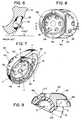
- Figure 7is a perspective view of a prosthesis constructed in accordance with the present invention from a single block of metal and having a bearing-receiving cavity which has been skewed to provide adduction correction.
- Figure 8is a plan view of the prosthesis of Figure 7.
- Figure 9is a cross-sectional view along lines 9-9 in Figure 8 of the prosthesis of Figure 7 with a skewed bearing element inserted into the prosthesis' skewed cavity.
- the centers of the two spherically-shaped portions of the outside surface of the cupare identified by the reference numbers 5 and 7.
- Figure 10is a perspective view of a prosthesis constructed in accordance with the present invention from a single block of metal and having a bearing-receiving cavity which has been skewed to provide both adduction and anteversion correction.
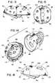
- Figure 11is an exploded, perspective view of a prosthesis constructed in accordance with the present invention from two components which when united produce an outside surface for the prosthesis which includes a cusp.
- Figure 12is a plan view of the cavity-containing component of the prosthesis of Figure 11.
- Figure 13is a side view of the assembled prosthesis of Figure 11.
- Figure 14is an exploded, perspective view of a prosthesis constructed in accordance with the present invention from two components which when united produce an outside surface for the prosthesis which has a central cylindrical portion.
- Figure 15is a plan view of the cavity-containing component of the prosthesis of Figure 14.
- Figure 16is a side view of the prosthesis of Figure 14.
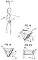
- Figure 17is a stylized, perspective view of a person showing the coronal (X-Z), transverse (X-Y) and sagittal (Y-Z) planes. A stylized portrayal of the person's pelvis is shown at 34.
- Figure 18is an enlarged view of the stylized pelvis 34. A stylized portrayal of the normal acetabulum is shown at 36.
- Figure 19is a coronal (X-Z) section along lines 19-19 in Figure 18 showing the desired adduction angle of approximately 45° for an acetabular prosthesis.
- Figure 20is a transverse (X-Y) section along lines 20-20 in Figure 18 showing the desired anteversion angle of approximately 15° for an acetabular prosthesis.
- Figure 21is a perspective view of a surgical instrument for use in implanting the prostheses of the present invention.
- Figure 22is a sectional view along lines 22-22 of the surgical instrument of Figure 21.
- Figure 23is a perspective view of a portion of a human pelvis showing the cavity formed in the pelvis through the use of the instrument of Figure 21.
- Figures 24-26are stylized views of prostheses constructed in accordance with the present invention showing the prosthesis' longitudinal plane and the plane defined by the opening of the prosthesis' bearing-receiving cavity.
- the prosthesis of Figure 24includes only adduction correction and thus can be used in either the patient's right or left hip.
- the prostheses of Figures 25 and 26include both adduction and anteversion correction and thus can be advantageously used in the right hip for the Figure 25 prosthesis and the left hip for the Figure 26 prosthesis.
- the prosthesisis made from a single block of material, e.g., a block of metal, and includes body 42 in which is formed cavity 13 for receiving bearing element 44.
- body 42also includes apertures 48 which 1) allow the surgeon to visualize the underlying bone as the prosthesis is implanted and 2) can receive bone screws for affixing the prosthesis to the pelvis.
- Bearing 44is retained in cavity 13 by means of 1) complimentary bayonet spaces 50 and lugs 52 formed at the mouth of the cavity which receive and mate with corresponding spaces and lugs formed on the outside surface of the bearing, and 2) bone screws (not shown) which pass through apertures 46 and lock the bearing to the prosthesis. See noisy U.S. Patents Nos. 4,801,301 and 4,960,427. Other means for securing the bearing to the cup can of course be used, if desired.
- prosthesis 40has a longitudinal axis defined by line OEG and a longitudinal plane which is defined by lines OEG and FEH and which contains line AOC.
- points O and Eare the centers of two spherically-shaped surfaces which form the ends of the oblong cup.
- the opening into bearing-receiving cavity 13defines a "first" plane which contains lines AOC and DOB.
- the opening into cavity 13 and thus the first planeis skewed with respect to the prosthesis' longitudinal plane so as to provide adduction correction or anteversion correction or both adduction correction and anteversion correction.
- the prosthesis of Figures 7-9shows the case of adduction correction only.
- the first planeis rotated out from the longitudinal plane by adduction correction angle GOB in Figure 7 which is also shown as angle A in Figure 9.
- the magnitude of the adduction correction anglewill generally be in the range of from about 10° to about 30°, although larger or smaller adduction correction angles can be used for particular applications if necessary or desired.
- Prostheses having adduction correction angles of different magnitudescan be provided to the surgeon so that a selection can be made at the time of implantation to better meet the needs of individual patients. For example, the surgeon can be given a choice between prostheses having adduction correction angles of 10, 20, and 30 degrees.
- the first plane and the longitudinal planeintersect along line AOC. Because only adduction correction is being performed, this line of intersection is perpendicular to the longitudinal axis of the oblong prosthesis, i.e., line AOC is perpendicular to line OEG. As discussed below, when both adduction and anteversion correction is performed, the angle between the longitudinal axis and the line of intersection is greater than 90° for a right hip cup and less than 90° for a left hip cup. When only anteversion correction is performed, the line of intersection between the first plane and the longitudinal plane is the longitudinal axis or, in the general case, is parallel to that axis.
- Figure 9shows the use of skewed bearing element 44 with cup 40. This combination allows for even greater adduction correction, i.e., correction through the sum of angles A and B in Figure 9. Also, by using an orientable bearing (see noisy U.S. Patent No. 4,678,472), some anteversion correction can be achieved for a cup having only adduction correction. Conversely, the use of an orientable, skewed bearing allows some adduction correction for a cup having only anteversion correction.
- bearing 44has strong mechanical support from the body of the cup even though the bearing's orientation is substantially different from that of the cup's longitudinal plane/axis.
- Figure 10shows an oblong cup having both adduction and anteversion correction.
- points O and Eare the centers of two spherically-shaped surfaces which form the ends of the oblong cup.
- the longitudinal axis of the cup of Figure 10is defined by line OEG
- the longitudinal plane of the cupis defined by lines OEG and FEH
- the first planecontains lines AOC and DOB
- the adduction correction angleis GOB.
- the longitudinal planedoes not contain line AOC, but rather contains the reference line JOK which is parallel to the reference line FEH.
- the angle between lines AOC and JOKi.e., angle JOA, represents the anteversion correction angle for this cup.
- the magnitude of the anteversion correction anglewill generally be in the range of from about 10° to about 30°, although larger or smaller anteversion correction angles can be used for particular applications if necessary or desired.
- prostheses having anteversion correction angles of different magnitudese.g., prostheses having anteversion correction angles of 10, 20, and 30 degrees, can be provided to the surgeon.
- the prosthesis of Figure 25, like that of Figure 10,is for a right hip and thus first plane 56 is rotated to the left relative to longitudinal plane 54.
- the Figure 26 prosthesis, on the other hand,is for a left hip and thus first plane 56 has been rotated to the right relative to the longitudinal plane.
- This aspect of the inventioncan also be seen by examining the angle W between the prosthesis' longitudinal axis 58 and the line of intersection 60 between the first plane and the longitudinal plane. As shown in Figure 25, for a right hip, angle W is greater than 90°, while as shown in Figure 26, for a left hip, it is less than 90°. For comparison, as shown in Figure 24, for a prosthesis with just adduction correction and no anteversion correction, angle W equals 90°.
- Figures 11-13 and 14-16show particularly preferred constructions for the prostheses of the present invention.
- body 42 of the prosthesisis composed of two components which engage and mate with each other along cylindrically-shaped surfaces.
- anteversion corrections of different magnitudes and right and left hip prosthesescan be easily constructed from a common set of components by simply joining the components together at different offset angles.
- component 62includes bearing-receiving cavity 13 and component 64 extends away from component 62 to produce the overall oblong shape of the cup.
- the outside, bone-engaging surfaces of both componentsare portions of a sphere. Accordingly, when the components are joined together, the outside surface of the assembled cup includes cusp 70 at the intersection between the two spherical portions.
- the overall length of the cupcan be adjusted by varying the size of component 64, i.e., by using more or less of a sphere to form the outside surface of this component. Also, the outside surfaces of the components can have different spherical radii to provide further flexibility in the overall configuration of the cup. As shown most clearly in Figure 13, face 72 of component 62 meets face 74 of component 64 at an angle so as to provide the assembled prosthesis with adduction correction.
- Components 62 and 64are joined together by means of cylindrically-shaped external surface 66 on component 62 and cylindrically-shaped internal surface 68 on component 64. To produce anteversion correction, the components are rotated relative to one another along these surfaces. When the desired degree and direction of anteversion correction has been selected, the components are permanently joined together by, for example, electron beam welding in a vacuum in the case of metal components.
- the prosthesis of Figures 11-13includes cusp 70 in its outside surface.
- a surgical instrument 94 suitable for preparing a cavity in a patient's pelvis for receiving such a prosthesisis shown in Figures 21 and 22.
- Instrument 94comprises spherical shell 84 and spherical reamer 76, which includes cutting blade 78 and chip clearance groove 80.
- the reameris driven by conventional means (not shown) through shaft 82.
- reamer 76 and shell 84correspond to the radii of the bone-engaging surfaces of components 64 and 62, respectively. Accordingly, the reamer and the shell can have different radii if components 64 and 62 have different radii.
- Platform 86includes holes 90 through which threaded bolt 88 can pass to attach shell 84 to the platform. Multiple holes are provided so that instrument 94 can be used with prostheses of different sizes, e.g., prostheses having larger and smaller components 64. Although only two adjustments are shown, more adjustments can, of course, be provided if a greater variety of prostheses is to be made available to the surgeon.
- FIG. 23The implantation of a prosthesis using the instrument of Figures 21 and 22 is illustrated in Figure 23.
- the surgeonprepares first spherical cavity 96 using a conventional reamer.
- the surgeoncuts second spherical cavity 98 using instrument 94.
- the surgeonplaces shell 84 into the first spherical cavity and uses the shell as a guide to cut the second cavity at a predetermined distance from the first cavity.
- the resultis finished cavity 32 which includes a ridge of bone 100 which will mate with cusp 70 in the outside surface of the prosthesis.
- Figures 14-16show a second two-component embodiment of the invention, again using cylindrically-shaped surfaces 66 and 68 at the interface between the components to allow for easy anteversion correction.
- component 102includes bearing-receiving cavity 13 and component 104 extends away from component 102 to produce the overall oblong shape of the cup.
- the outside, bone-engaging surface of component 102is a portion of a sphere, while the outside, bone-engaging surface of component 104 includes a spherical portion 106 and a cylindrical portion 108.
- adjustments in the overall length of the prosthesiscan be easily made by simply changing the length of cylindrical portion 108.
- face 110 of component 102meets face 112 of component 104 at an angle so as to provide the assembled prosthesis with adduction correction.
- FIG. 14-16has two, spaced-apart, outside, spherically-shaped surfaces, and thus an instrument of the type shown in Figures 21 and 22 can advantageously be used to produce a cavity in the patient's pelvis for this prosthesis as described above. Because the prosthesis does not include a cusp, a conventional reamer is advantageously used to form a continuous cylindrical connection between the spaced-apart, spherically-shaped sections of the cavity resulting from the use of instrument 94. The finished cavity thus includes two spherically-shaped portions and a cylindrically-shaped portion corresponding to the outside surface of the prosthesis.
- the prostheses of the inventionare preferably implanted by being press fit into the prepared cavity in the patient's bone. Bone screws which pass through screw holes 48 can be used to provide additional fixation for the prosthesis.
- the outside surface of the prosthesisincludes porous coating 113 to provide long term fixation through bone ingrowth.
- the prosthesis with its porous coatingis dimensioned approximately 1 millimeter larger in diameter than the cavity.
- the prostheses of the inventioncan be made of conventional materials known in the art for making artificial joint replacements.
- the body of the cupcan be made of a Ti 6Al 4V alloy
- the porous coatingcan be chemically pure titanium
- the bearingcan be ultra high molecular weight polyethylene.
- Other materials now known or subsequently developedcan of course be used in the practice of the invention.
- the prostheses of the inventioncan be manufactured using conventional techniques known in the art such as through the use of computer controlled machine tools.
- outside surface of the prosthesiscan have configurations other than those shown, a variety of instruments other than that shown in Figures 21 and 22 can be used to prepare a cavity for the prosthesis, and methods different from those illustrated can be used to join together the various parts of the prosthesis.
- the geometry of the prosthesiscan be described in terms different from those used above.
- the prosthesiscan be described in terms of the shape of its outer surface and the central axis of the cavity which receives the bearing element.
- the prosthesis' outer surfaceincludes two spherically-shaped portions, the centers of which spheres are spaced-apart and thus define a line.
- the central axis of the bearing-receiving cavitywas perpendicular to the line between the centers of the spheres.
- the central axisintersects the line between the centers at an angle other than 90°.
Landscapes
- Health & Medical Sciences (AREA)
- Orthopedic Medicine & Surgery (AREA)
- Life Sciences & Earth Sciences (AREA)
- Animal Behavior & Ethology (AREA)
- Public Health (AREA)
- Engineering & Computer Science (AREA)
- Biomedical Technology (AREA)
- Heart & Thoracic Surgery (AREA)
- Transplantation (AREA)
- Oral & Maxillofacial Surgery (AREA)
- Veterinary Medicine (AREA)
- General Health & Medical Sciences (AREA)
- Vascular Medicine (AREA)
- Cardiology (AREA)
- Surgery (AREA)
- Physical Education & Sports Medicine (AREA)
- Dentistry (AREA)
- Nuclear Medicine, Radiotherapy & Molecular Imaging (AREA)
- Medical Informatics (AREA)
- Molecular Biology (AREA)
- Prostheses (AREA)
- Surgical Instruments (AREA)
Abstract
Description
said cavity having an opening formed in a portion ofsaid second outer surface which defines a first plane saidfirst plane forming an acute angle with said longitudinalplane.
said cavity having an opening formed in a portion ofsaid second outer surface which defines a first plane, saidfirst plane intersecting said longitudinal plane at anangle greater than 0°.
Claims (8)
- An acetabular cup (40) comprising a body (42)having:(a) a first outer surface for engagement withbone,(b) a second outer surface having an overalloblong configuration which defines a longitudinal plane(OEG-FEH) and a longitudinal axis (OEG), and(c) a cavity (13) formed in the body forreceiving a bearing element (44),
said cavity (13) having an opening formed in aportion of said second outer surface which defines a firstplane (AOC-DOB), said first plane forming an acute angle(GOB) with said longitudinal plane. - The acetabular cup of claim 1, wherein theacute angle (GOB):(i) is in a direction along the longitudinal axis(OEG) such that when the acetabular cup (40) is implantedin the patient's pelvis said first plane (AOC-DOB) is moreadducted than the longitudinal plane (OEG-FEH); or(ii) is in a direction transverse to thelongitudinal axis (OEG) such that when the acetabular cup(40) is implanted in the patient's pelvis said first plane(AOC-DOB) is more anteverted than the longitudinal plane(OEG-FEH); or(iii) both (i) and (ii).
- An acetabular cup (40) comprising a body (42) having:(a) a first outer surface for engagement withbone,(b) a second outer surface having an overalloblong configuration which defines a longitudinal plane(OEG-FEH) and a longitudinal axis (OEG), and(c) a cavity (13) formed in the body forreceiving a bearing element (44),
said cavity (13) having an opening formed in aportion of said second outer surface which defines a firstplane (AOC-DOB), said first plane intersecting saidlongitudinal plane at an angle (GOB) greater than 0°. - The acetabular cup of claim 3 wherein the angle (W)between the longitudinal axis (58) and the line ofintersection (60) between the first plane (56) and thelongitudinal plane (54) is:(i) equal to 90°; or(ii) greater than 90°; or(iii) less than 90°.
- The acetabular cup of any one of the precedingclaims, wherein the first outer surface comprises a firstportion which is generally spherically-shaped about a firstcenter (O) and a second portion which is generallyspherically-shaped about a second center (E) which isdisplaced from the first center (O).
- The acetabular cup of claim 5, wherein thefirst and second portions have substantially equal radii.
- The acetabular cup of claim 5, wherein thefirst and second portions meet one another to form a cusp(70).
- The acetabular cup of claim 5, wherein thefirst outer surface further comprises a generallycylindrically-shaped portion (108) which connects the firstand second portions.
Priority Applications (2)
| Application Number | Priority Date | Filing Date | Title |
|---|---|---|---|
| EP97114360AEP0809984B1 (en) | 1991-03-07 | 1992-03-06 | Cutting instrument for oblong acetabular cups |
| EP97114362AEP0809985B1 (en) | 1991-03-07 | 1992-03-06 | Oblong acetabular cup |
Applications Claiming Priority (3)
| Application Number | Priority Date | Filing Date | Title |
|---|---|---|---|
| US665952 | 1991-03-07 | ||
| US07/665,952US5192329A (en) | 1991-03-07 | 1991-03-07 | Oblong acetabular cup |
| PCT/US1992/001874WO1992015261A1 (en) | 1991-03-07 | 1992-03-06 | Oblong acetabular cup |
Related Child Applications (2)
| Application Number | Title | Priority Date | Filing Date |
|---|---|---|---|
| EP97114360ADivisionEP0809984B1 (en) | 1991-03-07 | 1992-03-06 | Cutting instrument for oblong acetabular cups |
| EP97114362ADivisionEP0809985B1 (en) | 1991-03-07 | 1992-03-06 | Oblong acetabular cup |
Publications (3)
| Publication Number | Publication Date |
|---|---|
| EP0574521A1 EP0574521A1 (en) | 1993-12-22 |
| EP0574521A4 EP0574521A4 (en) | 1994-07-20 |
| EP0574521B1true EP0574521B1 (en) | 1998-05-13 |
Family
ID=24672216
Family Applications (3)
| Application Number | Title | Priority Date | Filing Date |
|---|---|---|---|
| EP97114360AExpired - LifetimeEP0809984B1 (en) | 1991-03-07 | 1992-03-06 | Cutting instrument for oblong acetabular cups |
| EP92908489AExpired - LifetimeEP0574521B1 (en) | 1991-03-07 | 1992-03-06 | Oblong acetabular cup |
| EP97114362AExpired - LifetimeEP0809985B1 (en) | 1991-03-07 | 1992-03-06 | Oblong acetabular cup |
Family Applications Before (1)
| Application Number | Title | Priority Date | Filing Date |
|---|---|---|---|
| EP97114360AExpired - LifetimeEP0809984B1 (en) | 1991-03-07 | 1992-03-06 | Cutting instrument for oblong acetabular cups |
Family Applications After (1)
| Application Number | Title | Priority Date | Filing Date |
|---|---|---|---|
| EP97114362AExpired - LifetimeEP0809985B1 (en) | 1991-03-07 | 1992-03-06 | Oblong acetabular cup |
Country Status (7)
| Country | Link |
|---|---|
| US (3) | US5192329A (en) |
| EP (3) | EP0809984B1 (en) |
| JP (2) | JP3411275B2 (en) |
| AU (3) | AU662737B2 (en) |
| CA (1) | CA2104231C (en) |
| DE (3) | DE69233509T2 (en) |
| WO (1) | WO1992015261A1 (en) |
Families Citing this family (119)
| Publication number | Priority date | Publication date | Assignee | Title |
|---|---|---|---|---|
| DE59205174D1 (en)* | 1992-01-16 | 1996-03-07 | Sulzer Medizinaltechnik Ag | Two-piece acetabular cup |
| DE59209116D1 (en)* | 1992-09-01 | 1998-02-12 | Sulzer Orthopaedie Ag | Double-shell revision acetabular cup |
| US5326368A (en)* | 1992-09-22 | 1994-07-05 | Howmedica, Inc. | Modular acetabular cup |
| US5507824A (en)* | 1993-02-23 | 1996-04-16 | Lennox; Dennis W. | Adjustable prosthetic socket component, for articulating anatomical joints |
| US5443519A (en)* | 1993-04-22 | 1995-08-22 | Implex Corporation | Prosthetic ellipsoidal acetabular cup |
| US5480448A (en)* | 1993-09-20 | 1996-01-02 | Mikhail; W. E. Michael | Acetabular cup groove insert |
| US5549701A (en)* | 1993-09-20 | 1996-08-27 | Mikhail; W. E. Michael | Acetabular cup |
| US5376092A (en)* | 1993-11-18 | 1994-12-27 | Orthopaedic Innovations, Inc. | Reamer for shaping bone sockets |
| FR2715556B1 (en)* | 1994-02-03 | 1996-04-12 | Landanger Landos | Cotyloid implant. |
| US5658347A (en)* | 1994-04-25 | 1997-08-19 | Sarkisian; James S. | Acetabular cup with keel |
| US5556434A (en)* | 1995-03-06 | 1996-09-17 | Epstein; Norman | Replacement hip joint |
| US6152963A (en) | 1996-01-04 | 2000-11-28 | Joint Medical Products Corporation | Method and apparatus for fitting a prosthesis to a bone |
| US6087553A (en)* | 1996-02-26 | 2000-07-11 | Implex Corporation | Implantable metallic open-celled lattice/polyethylene composite material and devices |
| US5702477A (en)* | 1996-05-09 | 1997-12-30 | Osteonics Corp. | Acetabular shell with supplemental support and method |
| WO1998010721A1 (en) | 1996-09-11 | 1998-03-19 | Plus Endoprothetik Ag | Shinbone element of knee joint prothesis |
| DE19647155C2 (en)* | 1996-11-14 | 1998-11-19 | Plus Endoprothetik Ag | Implant |
| ATE232069T1 (en)* | 1996-11-21 | 2003-02-15 | Plus Endoprothetik Ag | JOINT SOCKET FOR A HIP JOINT PROSTHESIS |
| DE19701778C2 (en)* | 1996-11-21 | 1999-03-11 | Plus Endoprothetik Ag | Joint socket for a hip joint endoprosthesis |
| US5871548A (en)* | 1996-12-07 | 1999-02-16 | Johnson & Johnson Professional, Inc. | Modular acetabular reinforcement system |
| FR2758255B1 (en)* | 1997-01-16 | 1999-07-16 | Groupe Lepine | "REPEAT" COTYLOID IMPLANT |
| DE19731442A1 (en)* | 1997-07-22 | 1999-02-11 | Plus Endoprothetik Ag | Cup for a joint endoprosthesis |
| US6139582A (en)* | 1997-11-21 | 2000-10-31 | Depuy Orthopaedics, Inc. | Acetabular cup with bi-directional steps |
| US6187050B1 (en) | 1997-12-29 | 2001-02-13 | Johnson & Johnson Professional, Inc. | Oblong acetabular cup |
| US5919195A (en)* | 1998-01-20 | 1999-07-06 | Johnson & Johnson Professional, Inc. | Oblong acetabular component instrumentation |
| CH692600A5 (en)* | 1998-04-02 | 2002-08-30 | Precimed Sa | surgical burr. |
| US5928288A (en)* | 1998-05-13 | 1999-07-27 | Johnson & Johnson Professional, Inc. | Variable fit oblong acetabular prosthesis |
| US6063091A (en) | 1998-10-13 | 2000-05-16 | Stryker Technologies Corporation | Methods and tools for tibial intermedullary revision surgery and associated tibial components |
| US6152930A (en)* | 1998-10-28 | 2000-11-28 | Depuy Orthopaedics, Inc. | Acetabular cup extraction system |
| IT1303805B1 (en)* | 1998-12-01 | 2001-02-23 | Bridgehall Consultants Ltd | REVISION COTILE FOR USE IN THE TREATMENT OF HIP PATHOLOGIES. |
| US6416553B1 (en) | 1999-03-31 | 2002-07-09 | Biomet, Inc. | Method and apparatus for providing a modular acetabular prosthesis |
| FR2805150B1 (en)* | 2000-02-21 | 2004-12-10 | Groupe Lepine | COTYLOIDIAN IMPLANT SAID "REPEAT" AND SET OF SUCH IMPLANTS |
| US6258097B1 (en)* | 2000-06-02 | 2001-07-10 | Bristol-Myers Squibb Co | Head center instrument and method of using the same |
| JP2004516060A (en) | 2000-12-21 | 2004-06-03 | プレシメッド エス.アー. | Holder for surgical reamer |
| US7497874B1 (en) | 2001-02-23 | 2009-03-03 | Biomet Manufacturing Corp. | Knee joint prosthesis |
| US20020120340A1 (en) | 2001-02-23 | 2002-08-29 | Metzger Robert G. | Knee joint prosthesis |
| US8123814B2 (en) | 2001-02-23 | 2012-02-28 | Biomet Manufacturing Corp. | Method and appartus for acetabular reconstruction |
| US7713306B2 (en)* | 2001-02-23 | 2010-05-11 | Biomet Manufacturing Corp. | Method and apparatus for acetabular reconstruction |
| US7597715B2 (en)* | 2005-04-21 | 2009-10-06 | Biomet Manufacturing Corp. | Method and apparatus for use of porous implants |
| US6458161B1 (en)* | 2001-02-23 | 2002-10-01 | Biomet, Inc. | Method and apparatus for acetabular reconstruction |
| US20040162619A1 (en) | 2001-08-27 | 2004-08-19 | Zimmer Technology, Inc. | Tibial augments for use with knee joint prostheses, method of implanting the tibial augment, and associated tools |
| US20030065397A1 (en)* | 2001-08-27 | 2003-04-03 | Hanssen Arlen D. | Prosthetic implant support structure |
| US7892288B2 (en)* | 2001-08-27 | 2011-02-22 | Zimmer Technology, Inc. | Femoral augments for use with knee joint prosthesis |
| US6682567B1 (en) | 2001-09-19 | 2004-01-27 | Biomet, Inc. | Method and apparatus for providing a shell component incorporating a porous ingrowth material and liner |
| FR2833478B1 (en)* | 2001-12-13 | 2004-08-13 | Science Medecine Sa | RECOVERY COTYLOID IMPLANT AND BONE SITE MILLING DEVICE FOR RECEIVING THIS IMPLANT |
| GB0207170D0 (en) | 2002-03-26 | 2002-05-08 | Mcminn Derek J W | Hip joint prosthesis |
| US7344565B2 (en)* | 2003-02-04 | 2008-03-18 | Wright Medical Technology, Inc. | Acetabular component insertion and extraction tool for use therewith, and method of locking an acetabular component to an insertion and extraction tool |
| WO2004071310A1 (en)* | 2003-02-10 | 2004-08-26 | Smith & Nephew, Inc. | Acetabular reamer |
| US7887544B2 (en)* | 2003-03-10 | 2011-02-15 | Tornier Sas | Ancillary tool for positioning a glenoid implant |
| US8298292B2 (en)* | 2003-04-16 | 2012-10-30 | Howmedica Osteonics Corp. | Craniofacial implant |
| KR20100102753A (en)* | 2003-04-16 | 2010-09-24 | 포렉스 서지칼, 인크. | Craniofacial implant |
| GB0313444D0 (en)* | 2003-06-11 | 2003-07-16 | Midland Medical Technologies L | Modular dysplasia cup |
| FR2859099B1 (en)* | 2003-08-25 | 2006-01-06 | Tornier Sa | GLENOIDAL COMPONENT OF SHOULDER PROSTHESIS AND TOTAL SHOULDER PROSTHESIS INCORPORATING SUCH COMPONENT |
| FR2863865B1 (en)* | 2003-12-19 | 2006-10-06 | Tornier Sa | SHOULDER OR HIP PROSTHESIS AND METHOD OF MOUNTING |
| DE502004002530D1 (en)* | 2004-02-25 | 2007-02-15 | Zimmer Gmbh | pelvic endoprosthesis |
| US7169185B2 (en)* | 2004-05-26 | 2007-01-30 | Impact Science And Technology, Inc. | Canine acetabular cup |
| US20050273109A1 (en)* | 2004-06-02 | 2005-12-08 | Minnesota Scientific, Inc. | Computer controlled reaming device |
| US8303665B2 (en) | 2004-06-15 | 2012-11-06 | Tornier Sas | Glenoidal component, set of such components and shoulder prosthesis incorporating such a glenoidal component |
| US7678150B2 (en)* | 2004-06-15 | 2010-03-16 | Tornier Sas | Total shoulder prosthesis of an inverted type |
| FR2871371B1 (en)* | 2004-06-15 | 2007-04-06 | Tornier Sas | GLENOIDAL COMPONENT OF SHOULDER PROSTHESIS, SET OF COMPONENT ELEMENTS OF SUCH COMPONENT AND TOTAL SHOULDER PROSTHESIS INCORPORATING SUCH COMPONENT |
| FR2872025B1 (en) | 2004-06-28 | 2006-08-25 | Tornier Sas | PROSTHESIS OF SHOULDER OR HIP |
| US7918896B2 (en)* | 2004-09-15 | 2011-04-05 | Wright Medical Technology, Inc. | Unitary acetabular cup prosthesis with extension for deficient acetabulum |
| US8317797B2 (en) | 2005-02-08 | 2012-11-27 | Rasmussen G Lynn | Arthroplasty systems and methods for optimally aligning and tensioning a knee prosthesis |
| US7927336B2 (en)* | 2005-02-08 | 2011-04-19 | Rasmussen G Lynn | Guide assembly for guiding cuts to a femur and tibia during a knee arthroplasty |
| US8303597B2 (en) | 2005-02-08 | 2012-11-06 | Rasmussen G Lynn | Systems and methods for guiding cuts to a femur and tibia during a knee arthroplasty |
| US20060190089A1 (en)* | 2005-02-18 | 2006-08-24 | Howmedica Osteonics Corp. | Internal adaptor for hip acetabular cage |
| US7763031B2 (en)* | 2005-03-01 | 2010-07-27 | Howmedica Osteonics Corp. | Acetabular shell removal instrument |
| US8266780B2 (en)* | 2005-04-21 | 2012-09-18 | Biomet Manufacturing Corp. | Method and apparatus for use of porous implants |
| US8066778B2 (en)* | 2005-04-21 | 2011-11-29 | Biomet Manufacturing Corp. | Porous metal cup with cobalt bearing surface |
| US8021432B2 (en) | 2005-12-05 | 2011-09-20 | Biomet Manufacturing Corp. | Apparatus for use of porous implants |
| US8292967B2 (en)* | 2005-04-21 | 2012-10-23 | Biomet Manufacturing Corp. | Method and apparatus for use of porous implants |
| US20070106392A1 (en)* | 2005-11-08 | 2007-05-10 | Howmedica Osteonics Corp. | Acetabular cup locking mechanism |
| US7635447B2 (en)* | 2006-02-17 | 2009-12-22 | Biomet Manufacturing Corp. | Method and apparatus for forming porous metal implants |
| JP5296667B2 (en) | 2006-03-20 | 2013-09-25 | スミス アンド ネフュー インコーポレーテッド | Acetabular cup assembly for multiple bearing elements |
| WO2007109319A2 (en)* | 2006-03-21 | 2007-09-27 | Axiom Orthopaedics, Inc. | Glenoid component with improved fixation stability |
| WO2007109340A2 (en)* | 2006-03-21 | 2007-09-27 | Axiom Orthopaedics, Inc. | Femoral and humeral stem geometry and implantation method for orthopedic joint reconstruction |
| EP1996123B1 (en)* | 2006-03-21 | 2019-08-28 | Tornier, Inc. | Non-spherical articulating surfaces in shoulder and hip prosthesis |
| FR2899790B1 (en)* | 2006-04-13 | 2008-06-13 | Tornier Sas | GLENOIDAL COMPONENT FOR TOTAL SHOULDER PROSTHESIS, SET OF SUCH COMPONENTS, AND TOTAL SHOULDER PROSTHESIS COMPRISING SUCH A COMPONENT |
| FR2900045B1 (en)* | 2006-04-21 | 2009-01-16 | Tornier Sas | PROSTHESIS OF SHOULDER OR HIP |
| US7670343B2 (en)* | 2006-06-14 | 2010-03-02 | Biomet Manufacturing Corp. | Method and apparatus for reaming an acetabulum |
| US20080021568A1 (en)* | 2006-07-07 | 2008-01-24 | Howmedica Osteonics Corp. | Acetabular cup augment system |
| DE102007031669A1 (en)* | 2006-08-04 | 2008-09-11 | Ceramtec Ag Innovative Ceramic Engineering | Asymmetrical design of acetabular cups to reduce cup deformations |
| US8562616B2 (en) | 2007-10-10 | 2013-10-22 | Biomet Manufacturing, Llc | Knee joint prosthesis system and method for implantation |
| US8187280B2 (en) | 2007-10-10 | 2012-05-29 | Biomet Manufacturing Corp. | Knee joint prosthesis system and method for implantation |
| US8328873B2 (en) | 2007-01-10 | 2012-12-11 | Biomet Manufacturing Corp. | Knee joint prosthesis system and method for implantation |
| US8163028B2 (en) | 2007-01-10 | 2012-04-24 | Biomet Manufacturing Corp. | Knee joint prosthesis system and method for implantation |
| JP5448842B2 (en) | 2007-01-10 | 2014-03-19 | バイオメト マニファクチャリング コーポレイション | Knee joint prosthesis system and implantation method |
| US20090287309A1 (en) | 2007-01-30 | 2009-11-19 | Tornier Sas | Intra-articular joint replacement |
| FR2911773B1 (en) | 2007-01-30 | 2009-03-27 | Tornier Sas | METHOD AND ASSEMBLY OF SURGICAL INSTRUMENTATION FOR POSITIONING A TOTAL REVERSE SHOULDER PROSTHESIS, AND CORRESPONDING PROSTHESIS |
| US7998146B2 (en)* | 2007-02-12 | 2011-08-16 | Innomed, Inc. | Apparatus and method for hip cup extraction |
| US9044345B2 (en)* | 2007-05-22 | 2015-06-02 | Brainlab Ag | Navigated placement of pelvic implant based on combined anteversion by applying Ranawat's sign or via arithmetic formula |
| CN101842062B (en)* | 2007-09-25 | 2013-04-03 | 拜欧米特制造公司 | Method for manufacturing cementless tibial tray |
| US20090088757A1 (en)* | 2007-10-02 | 2009-04-02 | Howmedica Osteonics Corp. | Acetabular reamer |
| US7993408B2 (en)* | 2008-02-12 | 2011-08-09 | Biomet Manufacturing Corp. | Acetabular cup having an adjustable modular augment |
| GB0809721D0 (en)* | 2008-05-28 | 2008-07-02 | Univ Bath | Improvements in or relating to joints and/or implants |
| US7985260B2 (en) | 2008-06-30 | 2011-07-26 | Depuy Products, Inc. | Acetabular prosthesis system |
| US8211184B2 (en)* | 2009-04-20 | 2012-07-03 | Michael D. Ries | Acetabular cup |
| US9512445B2 (en) | 2009-08-31 | 2016-12-06 | The Cleveland Clinic Foundation | Humeral joint replacement component |
| US8506569B2 (en)* | 2009-12-31 | 2013-08-13 | DePuy Synthes Products, LLC | Reciprocating rasps for use in an orthopaedic surgical procedure |
| US8556901B2 (en) | 2009-12-31 | 2013-10-15 | DePuy Synthes Products, LLC | Reciprocating rasps for use in an orthopaedic surgical procedure |
| US20120179270A1 (en)* | 2010-03-10 | 2012-07-12 | Russell Nevins | Low stress multiple fixation acetabular component |
| US9408652B2 (en) | 2010-04-27 | 2016-08-09 | Tornier Sas | Intra-articular joint replacement and method |
| FR2966343B1 (en) | 2010-10-22 | 2012-12-07 | Tornier Sa | SET OF GLENOIDIAN COMPONENTS OF SHOULDER PROSTHESIS |
| US8486076B2 (en) | 2011-01-28 | 2013-07-16 | DePuy Synthes Products, LLC | Oscillating rasp for use in an orthopaedic surgical procedure |
| US9060862B2 (en) | 2011-07-08 | 2015-06-23 | Floyd Franklin Castro | Semi-constrained ball and socket joints |
| EP2787929B1 (en) | 2011-12-07 | 2019-05-15 | Smith&Nephew, Inc. | Orthopedic augments having recessed pockets |
| JP6282596B2 (en) | 2011-12-07 | 2018-02-21 | スミス アンド ネフュー インコーポレイテッド | Orthopedic implant augment |
| AU2013379741B2 (en) | 2013-03-01 | 2018-08-30 | Stryker Corporation | Acetabular cup remover with indexing assembly for rotating the removal blade around the cup |
| US9044195B2 (en) | 2013-05-02 | 2015-06-02 | University Of South Florida | Implantable sonic windows |
| US10456262B2 (en) | 2016-08-02 | 2019-10-29 | Howmedica Osteonics Corp. | Patient-specific implant flanges with bone side porous ridges |
| US12414862B2 (en) | 2016-11-30 | 2025-09-16 | G. Lynn Rasmussen | Systems and methods for providing a tibial baseplate system |
| JP2020500600A (en) | 2016-11-30 | 2020-01-16 | ジー リン ラスムッセン | System and method for providing a tibial baseplate |
| CA3051099C (en) | 2017-01-20 | 2022-07-12 | Biomet Manufacturing, Llc | Modular augment component |
| RU187804U1 (en)* | 2018-07-31 | 2019-03-19 | Федеральное государственное бюджетное учреждение "Новосибирский научно-исследовательский институт травматологии и ортопедии им. Я.Л. Цивьяна" Министерства здравоохранения Российской Федерации (ФГБУ "ННИИТО им. Я.Л. Цивьяна" Минздрава России) | Device for replacing a bone defect in the acetabulum |
| RU2713519C1 (en)* | 2018-07-31 | 2020-02-05 | Федеральное государственное бюджетное учреждение "Новосибирский научно-исследовательский институт травматологии и ортопедии им. Я.Л. Цивьяна" Министерства здравоохранения Российской Федерации (ФГБУ "ННИИТО им. Я.Л. Цивьяна" Минздрава России) | Device for cotyloid defect replacement in cotyloid cavity |
| EP3666228A1 (en)* | 2018-12-14 | 2020-06-17 | Howmedica Osteonics Corp. | Augmented, just-in-time, patient-specific implant manufacture |
| CN109481093B (en)* | 2018-12-17 | 2024-04-19 | 北京安颂科技有限公司 | Artificial acetabulum prosthesis and method of installing the same |
| US11395741B2 (en) | 2019-05-16 | 2022-07-26 | Howmedica Osteonics Corp. | Joint replacement augments and associated instrumentation |
| CN113408151B (en)* | 2021-07-15 | 2022-10-11 | 广东工业大学 | Navigation method and system for acetabular cup implantation aided by acetabular collapse reconstruction technology |
| US11944544B2 (en) | 2021-11-19 | 2024-04-02 | Arthrology Consulting, Llc | Expandable augment system for acetabular cup |
Family Cites Families (27)
| Publication number | Priority date | Publication date | Assignee | Title |
|---|---|---|---|---|
| US3633583A (en)* | 1969-08-22 | 1972-01-11 | Meyer Fishbein | Orthopedic single-blade bone cutter |
| GB1409051A (en)* | 1971-09-24 | 1975-10-08 | Nat Research Department Corp | Hip joint prostheses |
| IT977435B (en)* | 1973-02-21 | 1974-09-10 | Battiato M | TOTAL HIP PROSTHESIS AND INSTRUMENTS FOR THE APPLICATION OF THE ACETABULAR PART |
| FR2260980B1 (en)* | 1974-02-20 | 1976-12-03 | Herbert Jules | |
| CH644511A5 (en)* | 1980-04-28 | 1984-08-15 | Sulzer Ag | Acetabulum |
| FR2516377A1 (en)* | 1981-11-13 | 1983-05-20 | Breard Francis | Artificial hip joint socket - has external face joined to cavity wall by spherical sector with grooved outer surface |
| DE3364860D1 (en)* | 1982-04-07 | 1986-09-04 | Nat Res Dev | Endoprosthetic bone joint devices |
| US4960427A (en)* | 1983-03-08 | 1990-10-02 | Joint Medical Products Corporation | Ball and socket bearing for artifical joint |
| US4678472A (en)* | 1983-03-08 | 1987-07-07 | Joint Medical Products Corporation | Ball and socket bearing for artificial joint |
| US4801301A (en)* | 1983-03-08 | 1989-01-31 | Joint Medical Products Corporation | Ball and socket bearing for artificial joint |
| CH659579A5 (en)* | 1983-06-07 | 1987-02-13 | Sulzer Ag | CEMENT-FREE ANCHORABLE HIP PAN. |
| DE3520663A1 (en)* | 1985-06-08 | 1986-12-18 | GMT Gesellschaft für medizinische Technik mbH, 2000 Hamburg | PAN FOR AN ARTIFICIAL HIP JOINT |
| US4711233A (en)* | 1985-06-26 | 1987-12-08 | Brown Byron L | Method and apparatus for cementing an acetabular cup to an acetabulum |
| US4712951A (en)* | 1985-08-26 | 1987-12-15 | Brown Byron L | Tool for cutting annular groove |
| CA1290099C (en)* | 1986-01-21 | 1991-10-08 | Thomas H. Mallory | Porous-coated artificial joints |
| FR2596642B1 (en)* | 1986-04-04 | 1988-06-24 | Demeulenaere Claude | HIP PROSTHESIS |
| CH670198A5 (en)* | 1986-10-02 | 1989-05-31 | Sulzer Ag | |
| CH671687A5 (en)* | 1987-03-30 | 1989-09-29 | Sulzer Ag | |
| DE8711039U1 (en)* | 1987-08-13 | 1987-10-15 | Howmedica GmbH, 2314 Schönkirchen | Joint socket for a hip joint endoprosthesis |
| DE8711113U1 (en)* | 1987-08-15 | 1987-11-05 | Orthoplant Endoprothetik GmbH i.L., 28259 Bremen | Device for cutting a thread in a socket-shaped bone |
| DE3804239A1 (en)* | 1988-02-11 | 1989-08-24 | Karl Heinrich Prof Dr Taeger | JOINT PART FOR A JOINT PROSTHESIS |
| SU1561975A1 (en)* | 1988-04-22 | 1990-05-07 | Б. Г. Зимлицкий и Е. Д. Соломко | Endoprosthesis of hip joint cotyloid cavity |
| DE8810783U1 (en)* | 1988-06-06 | 1988-10-20 | Mecron Medizinische Produkte Gmbh, 1000 Berlin | Screw cup as part of a hip joint prosthesis |
| SU1630799A1 (en)* | 1989-03-20 | 1991-02-28 | Ленинградский научно-исследовательский институт травматологии и ортопедии им.Р.Р.Вредена | Device for making a socket in the hip bone |
| US5176710A (en)* | 1991-01-23 | 1993-01-05 | Orthopaedic Research Institute | Prosthesis with low stiffness factor |
| US5176711A (en)* | 1991-03-06 | 1993-01-05 | Grimes James B | Acetabular revision system |
| US5100409A (en)* | 1991-03-07 | 1992-03-31 | Dow Corning Wright Corporation | Shaping and trial reduction guide for implantation of femoral prosthesis and method of using same |
- 1991
- 1991-03-07USUS07/665,952patent/US5192329A/ennot_activeExpired - Lifetime
- 1992
- 1992-03-06AUAU15822/92Apatent/AU662737B2/ennot_activeExpired
- 1992-03-06EPEP97114360Apatent/EP0809984B1/ennot_activeExpired - Lifetime
- 1992-03-06WOPCT/US1992/001874patent/WO1992015261A1/enactiveIP Right Grant
- 1992-03-06EPEP92908489Apatent/EP0574521B1/ennot_activeExpired - Lifetime
- 1992-03-06DEDE69233509Tpatent/DE69233509T2/ennot_activeExpired - Lifetime
- 1992-03-06CACA002104231Apatent/CA2104231C/ennot_activeExpired - Lifetime
- 1992-03-06DEDE69233072Tpatent/DE69233072T2/ennot_activeExpired - Lifetime
- 1992-03-06EPEP97114362Apatent/EP0809985B1/ennot_activeExpired - Lifetime
- 1992-03-06JPJP50830692Apatent/JP3411275B2/ennot_activeExpired - Lifetime
- 1992-03-06DEDE69225472Tpatent/DE69225472T2/ennot_activeExpired - Lifetime
- 1992-12-14USUS07/989,834patent/US5290315A/ennot_activeExpired - Lifetime
- 1993
- 1993-11-24USUS08/158,035patent/US5370704A/ennot_activeExpired - Lifetime
- 1995
- 1995-12-04AUAU39186/95Apatent/AU686474B2/ennot_activeExpired
- 1997
- 1997-11-03AUAU43676/97Apatent/AU694906B2/ennot_activeExpired
- 2002
- 2002-04-23JPJP2002120594Apatent/JP3657240B2/ennot_activeExpired - Lifetime
Also Published As
| Publication number | Publication date |
|---|---|
| EP0809985B1 (en) | 2003-05-21 |
| EP0809984A3 (en) | 1999-07-28 |
| DE69233509D1 (en) | 2005-06-16 |
| JP3657240B2 (en) | 2005-06-08 |
| EP0574521A1 (en) | 1993-12-22 |
| AU686474B2 (en) | 1998-02-05 |
| US5290315A (en) | 1994-03-01 |
| EP0809985A3 (en) | 1999-07-28 |
| AU1582292A (en) | 1992-10-06 |
| EP0574521A4 (en) | 1994-07-20 |
| EP0809985A2 (en) | 1997-12-03 |
| DE69225472T2 (en) | 1999-01-28 |
| WO1992015261A1 (en) | 1992-09-17 |
| AU3918695A (en) | 1996-02-15 |
| EP0809984A2 (en) | 1997-12-03 |
| JP2003024352A (en) | 2003-01-28 |
| DE69233509T2 (en) | 2006-02-02 |
| EP0809984B1 (en) | 2005-05-11 |
| AU694906B2 (en) | 1998-07-30 |
| JP3411275B2 (en) | 2003-05-26 |
| CA2104231C (en) | 2004-12-21 |
| DE69233072T2 (en) | 2004-01-22 |
| AU4367697A (en) | 1998-01-15 |
| CA2104231A1 (en) | 1992-09-08 |
| JPH06505414A (en) | 1994-06-23 |
| DE69233072D1 (en) | 2003-06-26 |
| AU662737B2 (en) | 1995-09-14 |
| US5370704A (en) | 1994-12-06 |
| US5192329A (en) | 1993-03-09 |
| DE69225472D1 (en) | 1998-06-18 |
Similar Documents
| Publication | Publication Date | Title |
|---|---|---|
| EP0574521B1 (en) | Oblong acetabular cup | |
| US6702822B1 (en) | Method and apparatus for fitting a prosthesis to a bone | |
| US7044975B2 (en) | Joint prostheses and components thereof | |
| US4944759A (en) | Porous-coated artificial joints | |
| US4549319A (en) | Artificial joint fixation to bone | |
| US5176711A (en) | Acetabular revision system | |
| US4546501A (en) | Hip prosthesis | |
| US6126694A (en) | Universal distal broach and stem trial | |
| US5002578A (en) | Modular hip stem prosthesis apparatus and method | |
| US6117138A (en) | Instruments for forming bony cavity for implantable femoral, hip prosthesis | |
| EP3308746B1 (en) | Mobile bearing hip assembly having decoupled motion along multiple axes | |
| US4738681A (en) | Femoral-joint prosthetic device | |
| EP1402854A2 (en) | Reverse-type humeral prosthesis | |
| EP0622061B1 (en) | Femoral component for a hip prothesis | |
| USRE32488E (en) | Hip prosthesis | |
| US4895573A (en) | Femoral-joint prosthetic device | |
| WO2017165727A2 (en) | Total wrist prosthesis and related methods | |
| US20240261109A1 (en) | Methodology for Understanding Knee Anatomy and Design of an Anatomic System for Revision Knee Arthroplasty | |
| CA2114208C (en) | Prosthetic joint system for bone replacement |
Legal Events
| Date | Code | Title | Description |
|---|---|---|---|
| PUAI | Public reference made under article 153(3) epc to a published international application that has entered the european phase | Free format text:ORIGINAL CODE: 0009012 | |
| 17P | Request for examination filed | Effective date:19930817 | |
| AK | Designated contracting states | Kind code of ref document:A1 Designated state(s):DE ES FR GB IT | |
| A4 | Supplementary search report drawn up and despatched | ||
| AK | Designated contracting states | Kind code of ref document:A4 Designated state(s):DE ES FR GB IT | |
| 17Q | First examination report despatched | Effective date:19960320 | |
| GRAG | Despatch of communication of intention to grant | Free format text:ORIGINAL CODE: EPIDOS AGRA | |
| GRAG | Despatch of communication of intention to grant | Free format text:ORIGINAL CODE: EPIDOS AGRA | |
| GRAG | Despatch of communication of intention to grant | Free format text:ORIGINAL CODE: EPIDOS AGRA | |
| GRAH | Despatch of communication of intention to grant a patent | Free format text:ORIGINAL CODE: EPIDOS IGRA | |
| GRAH | Despatch of communication of intention to grant a patent | Free format text:ORIGINAL CODE: EPIDOS IGRA | |
| GRAA | (expected) grant | Free format text:ORIGINAL CODE: 0009210 | |
| AK | Designated contracting states | Kind code of ref document:B1 Designated state(s):DE ES FR GB IT | |
| DX | Miscellaneous (deleted) | ||
| PG25 | Lapsed in a contracting state [announced via postgrant information from national office to epo] | Ref country code:ES Free format text:THE PATENT HAS BEEN ANNULLED BY A DECISION OF A NATIONAL AUTHORITY Effective date:19980513 | |
| ITF | It: translation for a ep patent filed | ||
| REF | Corresponds to: | Ref document number:69225472 Country of ref document:DE Date of ref document:19980618 | |
| ET | Fr: translation filed | ||
| PLBE | No opposition filed within time limit | Free format text:ORIGINAL CODE: 0009261 | |
| 26N | No opposition filed | ||
| REG | Reference to a national code | Ref country code:GB Ref legal event code:IF02 | |
| PGFP | Annual fee paid to national office [announced via postgrant information from national office to epo] | Ref country code:IT Payment date:20110315 Year of fee payment:20 Ref country code:FR Payment date:20110317 Year of fee payment:20 | |
| PGFP | Annual fee paid to national office [announced via postgrant information from national office to epo] | Ref country code:DE Payment date:20110302 Year of fee payment:20 Ref country code:GB Payment date:20110302 Year of fee payment:20 | |
| REG | Reference to a national code | Ref country code:DE Ref legal event code:R071 Ref document number:69225472 Country of ref document:DE | |
| REG | Reference to a national code | Ref country code:DE Ref legal event code:R071 Ref document number:69225472 Country of ref document:DE | |
| REG | Reference to a national code | Ref country code:GB Ref legal event code:PE20 Expiry date:20120305 | |
| PG25 | Lapsed in a contracting state [announced via postgrant information from national office to epo] | Ref country code:DE Free format text:LAPSE BECAUSE OF EXPIRATION OF PROTECTION Effective date:20120307 | |
| PG25 | Lapsed in a contracting state [announced via postgrant information from national office to epo] | Ref country code:GB Free format text:LAPSE BECAUSE OF EXPIRATION OF PROTECTION Effective date:20120305 |