EP0569124B1 - Improved lancet actuator - Google Patents
Improved lancet actuatorDownload PDFInfo
- Publication number
- EP0569124B1 EP0569124B1EP93302444AEP93302444AEP0569124B1EP 0569124 B1EP0569124 B1EP 0569124B1EP 93302444 AEP93302444 AEP 93302444AEP 93302444 AEP93302444 AEP 93302444AEP 0569124 B1EP0569124 B1EP 0569124B1
- Authority
- EP
- European Patent Office
- Prior art keywords
- actuating mechanism
- cam
- advancement
- propulsion
- cocking
- Prior art date
- Legal status (The legal status is an assumption and is not a legal conclusion. Google has not performed a legal analysis and makes no representation as to the accuracy of the status listed.)
- Expired - Lifetime
Links
- 230000007246mechanismEffects0.000claimsdescription24
- 230000002441reversible effectEffects0.000claimsdescription5
- 230000003252repetitive effectEffects0.000claims2
- 238000004146energy storageMethods0.000claims1
- 238000005381potential energyMethods0.000claims1
- 230000033001locomotionEffects0.000description16
- 238000000034methodMethods0.000description7
- 239000008280bloodSubstances0.000description4
- 210000004369bloodAnatomy0.000description4
- 208000027418Wounds and injuryDiseases0.000description3
- 230000007935neutral effectEffects0.000description3
- 230000035515penetrationEffects0.000description3
- 238000010241blood samplingMethods0.000description2
- 230000006835compressionEffects0.000description2
- 238000007906compressionMethods0.000description2
- 238000000605extractionMethods0.000description2
- 208000014674injuryDiseases0.000description2
- 230000008733traumaEffects0.000description2
- 238000004804windingMethods0.000description2
- 230000009471actionEffects0.000description1
- 230000000994depressogenic effectEffects0.000description1
- 230000006872improvementEffects0.000description1
- 238000003780insertionMethods0.000description1
- 230000037431insertionEffects0.000description1
- 239000002184metalSubstances0.000description1
- 238000012986modificationMethods0.000description1
- 230000004048modificationEffects0.000description1
- 239000002991molded plasticSubstances0.000description1
- 230000006641stabilisationEffects0.000description1
- 238000011105stabilizationMethods0.000description1
- 230000007704transitionEffects0.000description1
Images


Classifications
- A—HUMAN NECESSITIES
- A61—MEDICAL OR VETERINARY SCIENCE; HYGIENE
- A61B—DIAGNOSIS; SURGERY; IDENTIFICATION
- A61B5/00—Measuring for diagnostic purposes; Identification of persons
- A61B5/15—Devices for taking samples of blood
- A61B5/151—Devices specially adapted for taking samples of capillary blood, e.g. by lancets, needles or blades
- A61B5/15186—Devices loaded with a single lancet, i.e. a single lancet with or without a casing is loaded into a reusable drive device and then discarded after use; drive devices reloadable for multiple use
- A—HUMAN NECESSITIES
- A61—MEDICAL OR VETERINARY SCIENCE; HYGIENE
- A61B—DIAGNOSIS; SURGERY; IDENTIFICATION
- A61B5/00—Measuring for diagnostic purposes; Identification of persons
- A61B5/15—Devices for taking samples of blood
- A61B5/150007—Details
- A61B5/150015—Source of blood
- A61B5/150022—Source of blood for capillary blood or interstitial fluid
- A—HUMAN NECESSITIES
- A61—MEDICAL OR VETERINARY SCIENCE; HYGIENE
- A61B—DIAGNOSIS; SURGERY; IDENTIFICATION
- A61B5/00—Measuring for diagnostic purposes; Identification of persons
- A61B5/15—Devices for taking samples of blood
- A61B5/150007—Details
- A61B5/150206—Construction or design features not otherwise provided for; manufacturing or production; packages; sterilisation of piercing element, piercing device or sampling device
- A61B5/150259—Improved gripping, e.g. with high friction pattern or projections on the housing surface or an ergonometric shape
- A—HUMAN NECESSITIES
- A61—MEDICAL OR VETERINARY SCIENCE; HYGIENE
- A61B—DIAGNOSIS; SURGERY; IDENTIFICATION
- A61B5/00—Measuring for diagnostic purposes; Identification of persons
- A61B5/15—Devices for taking samples of blood
- A61B5/150007—Details
- A61B5/150374—Details of piercing elements or protective means for preventing accidental injuries by such piercing elements
- A61B5/150381—Design of piercing elements
- A61B5/150412—Pointed piercing elements, e.g. needles, lancets for piercing the skin
- A—HUMAN NECESSITIES
- A61—MEDICAL OR VETERINARY SCIENCE; HYGIENE
- A61B—DIAGNOSIS; SURGERY; IDENTIFICATION
- A61B5/00—Measuring for diagnostic purposes; Identification of persons
- A61B5/15—Devices for taking samples of blood
- A61B5/151—Devices specially adapted for taking samples of capillary blood, e.g. by lancets, needles or blades
- A61B5/15101—Details
- A61B5/15103—Piercing procedure
- A61B5/15107—Piercing being assisted by a triggering mechanism
- A61B5/15113—Manually triggered, i.e. the triggering requires a deliberate action by the user such as pressing a drive button
- A—HUMAN NECESSITIES
- A61—MEDICAL OR VETERINARY SCIENCE; HYGIENE
- A61B—DIAGNOSIS; SURGERY; IDENTIFICATION
- A61B5/00—Measuring for diagnostic purposes; Identification of persons
- A61B5/15—Devices for taking samples of blood
- A61B5/151—Devices specially adapted for taking samples of capillary blood, e.g. by lancets, needles or blades
- A61B5/15101—Details
- A61B5/15115—Driving means for propelling the piercing element to pierce the skin, e.g. comprising mechanisms based on shape memory alloys, magnetism, solenoids, piezoelectric effect, biased elements, resilient elements, vacuum or compressed fluids
- A61B5/15117—Driving means for propelling the piercing element to pierce the skin, e.g. comprising mechanisms based on shape memory alloys, magnetism, solenoids, piezoelectric effect, biased elements, resilient elements, vacuum or compressed fluids comprising biased elements, resilient elements or a spring, e.g. a helical spring, leaf spring, or elastic strap
- A—HUMAN NECESSITIES
- A61—MEDICAL OR VETERINARY SCIENCE; HYGIENE
- A61B—DIAGNOSIS; SURGERY; IDENTIFICATION
- A61B5/00—Measuring for diagnostic purposes; Identification of persons
- A61B5/15—Devices for taking samples of blood
- A61B5/151—Devices specially adapted for taking samples of capillary blood, e.g. by lancets, needles or blades
- A61B5/15101—Details
- A61B5/15126—Means for controlling the lancing movement, e.g. 2D- or 3D-shaped elements, tooth-shaped elements or sliding guides
- A61B5/1513—Means for controlling the lancing movement, e.g. 2D- or 3D-shaped elements, tooth-shaped elements or sliding guides comprising linear sliding guides
- A—HUMAN NECESSITIES
- A61—MEDICAL OR VETERINARY SCIENCE; HYGIENE
- A61B—DIAGNOSIS; SURGERY; IDENTIFICATION
- A61B5/00—Measuring for diagnostic purposes; Identification of persons
- A61B5/15—Devices for taking samples of blood
- A61B5/151—Devices specially adapted for taking samples of capillary blood, e.g. by lancets, needles or blades
- A61B5/15186—Devices loaded with a single lancet, i.e. a single lancet with or without a casing is loaded into a reusable drive device and then discarded after use; drive devices reloadable for multiple use
- A61B5/15188—Constructional features of reusable driving devices
- A61B5/15192—Constructional features of reusable driving devices comprising driving means, e.g. a spring, for retracting the lancet unit into the driving device housing
- A61B5/15194—Constructional features of reusable driving devices comprising driving means, e.g. a spring, for retracting the lancet unit into the driving device housing fully automatically retracted, i.e. the retraction does not require a deliberate action by the user, e.g. by terminating the contact with the patient's skin
Definitions
- This inventionrelates to lancet devices for use by physicians and technicians or the patient to extract a blood sample, and more particularly relates to a mechanism for effecting the initial puncture and thereafter retracting the lancet needle following the skin puncturing procedure, all of which is done with smooth, linear movements to minimize patient discomfort and pain.
- the lancet actuator in accordance with the present inventionwhich provides improved patient comfort in that initial puncture and withdrawal of the lancet needle is effected in a continuous, smooth rapid motion so that little or no lateral movement can take place.
- the present inventionis an improvement on the lancet actuator described in U.S. Patent No. 5,196,025.
- the lancet disclosed in JP-A-64/42010includes a linkage member and a movement member with a linkage portion linked with the linkage member to advance and retract a lancet.
- a spring meansis also provided for moving the movement member in one direction and selection means are provided for selecting to prevent or permit moving of the movement member.
- the devicefurther includes a lever for returning the movement member after the lancing operation is complete.
- the preamble of claim 1is based on this document.
- An actuating mechanism in accordance with the present inventiondoes not include any linkage of the drive cam structure to the cam following means.
- Guide flangesare provided on the carriage means and cam following means, and slots are located in the housing which receive the guide flanges such that the guide flanges are slidably displaceable in the slots furthering the linearization of the advancement of the carriage means.
- an embodiment of a lancet actuator in accordance with the present inventionis generally designated by reference character 10.
- the actuator 10accommodates the use of conventional, disposable lancet needle-and-support-body units A.
- the units Acomprise a metal needle 11 carried by a molded plastic body B.
- a lancet unit Ais inserted into a lancet holder or carriage means 12 within the actuator 10, as more fully described hereinafter, prior to operation of the actuator 10 to puncture a patient's tissue in a blood sample extraction procedure, after which the lancet unit A is removed from the holder or carriage 12 for disposal.
- a split housing 13(one half only shown) has an access and operation aperture 13a formed at one end, through which the disposable lancet unit A is inserted and removed.
- the actuator 10also has a cap 15 which is snap-fitted to the housing 13 to cover the aperture 13a and the inserted lancet unit A during the blood extraction procedure, and therefore the cap 15 will be exposed to the blood sample and will consequently be disposable with the used lancet unit A.
- the cap 15includes an opening 15a through which the needle 11 of lancet A can project. The extension of the cap 15 determines the length of the projection of the needle portion 11 therefrom, and therefore also determines the puncture depth when the cap 15 is seated on the donor's skin.
- FIG. 4illustrates the mechanism of the actuator 10 preparatory to insertion of the lancet unit A and before the actuating mechanism has been cocked to prepare the actuator for operation.
- this condition of the actuator 10also corresponds to that as would occur after completion of a prior procedure.
- the lancet unit Ais positioned within the carriage or holder 12 and the cap 15 is snapped into place.
- the actuatoris then cocked to arrive at the position shown in FIG. 1, as explained more fully hereinafter, and is thus ready for operation.
- the lancet holder 12In operation of the actuator 10, the lancet holder 12 carries the lancet unit A from the retracted position shown in FIG. 1 to the linearly advanced position shown in FIG. 2 in which the lancet needle 11 projects from the opening 16 to puncture the tissue, and then immediately retracts the lancet unit A into the position shown in FIG. 3.
- FIGS. 1, 3 and 4illustrate the same retracted position of the holder 12, although FIG. 4 also shows the cap 15 detached and lancet unit A removed from the holder 12.
- the advancement and retraction of the lancet needleis not only linear, but is attained with a rapid, smooth movement to minimize patient discomfort.
- the lancet holder-carriage 12is integrally molded and connected with a cam-following structure 14 which transmits propulsion to the holder 12 for the advancement of the lancet unit A and needle 11.
- a pivoting, drive cam structure 16has a cam arm 17 which is engagable with the cam-following structure 14 in a wiping, cam action to propel the linear advancement of the cam-following structure 14 and holder 12 for the needle puncturing motion.
- the cam-following structure 14has a propulsion cam surface 18 which is translated by the propelling clockwise pivot of the drive cam structure 16 and arm 17 (FIG. 6) between the position in FIG. 1 and the position in FIG. 2.
- the cam-following structure 14also has a cocking cam surface 20 against which the cam arm 17 is engaged as the cam arm 17 continues in clockwise rotation from the position of FIG. 2 to the position of FIG. 3 when the cam-following structure 14 and holder 12 are retracted in reverse motion along the highly linear path and the lancet needle 11 is withdrawn from the tissue puncture.
- arm 17In the terminal position of holder advancement and needle penetration of FIG. 2, arm 17 is engaged with an arcuate, apex surface 21 which medially joins the propulsion and cocking cam surfaces 18 and 20.
- the clockwise rotation of the drive cam structure 16 and arm 17is driven by a torsion spring generally designated by reference character 22 which is wound around a hub portion 24 of the drive cam structure 16.
- the hub portion 24is journaled on a stationary pivot bearing pin 26 which projects inwardly from the housing half 14 as shown in FIGS. 1-4.
- the cam arm 17has a slot 19 which receives the movable end 28 of the torsion spring 22 so that the end 28 bears against and drives the clockwise rotation of the arm 17 (and the needle advancement stroke) as the torsion spring 22 unwinds.
- the advancement stroke of the cam-following structure 14 and holder 12also compresses a coil spring 30 which surrounds the forward portion of the holder 12; as best shown by comparison of FIGS.
- the stationary end 31 of the spring 30is seated on an annular shoulder 32 formed by the housing halves 14, and the movable spring end 33 is secured to an annular shoulder 34 formed on the exterior and midway along the holder 12.
- the compression of the spring 30 produced by the advancement of the holder 12is then releasable with expansion to provide the propulsion of the retraction stroke of the holder 12 as the drive cam arm 17 slides past the arcuate, apex surface 21 (which medially joins surfaces 18 and 20) and begins to slide against the cocking cam surface 20 as the cam arm 17 continues the clockwise pivot driven by the torsion spring 22.
- the expansion of the return spring 30provides a smoothly continuous retraction of the holder 12 immediately following its advancement so that the puncturing thrust of the lancet needle 11 is rapidly reversed on the same highly linear path which suppresses patient discomfort.
- the used lancet unit Ais ejected from the holder 12 by manually sliding the cocking structure 36 forwardly to the left from its neutral position as shown in FIG. 3 into the forward position shown in FIG. 4 so that the ejector arm 38 enters and passes through the slot 40 formed through the rear end of the holder 12.
- the ejector arm 38thereby engages and displaces the lancet body B for removal through the entrance of the holder 12.
- the cocking structure 36is then manually retracted to the neutral position shown in FIG.
- the ejector arm 38is arranged in laterally offset longitudinal alignment in relation to the cam surfaces 18 and 19 to enable relative clearance therebetween.
- the actuator 10After installing the new lancet unit A, and preparatory to the next blood sampling procedure, the actuator 10 remains in the position shown in FIG. 3 and must be armed in a cocking operation to achieve the position shown in FIG. 1 in readiness for a succeeding lancing procedure.
- the lancetcan be installed either before or after the unit is cocked.
- the cocking structure 36In the arming or cocking operation, the cocking structure 36 is slidably displaced rearwardly to the right from the position shown in FIG. 3 so that the cocking arm 42 thereof is moved into engagement with a transversely projecting cocking pin 44 extending from the drive cam structure 16 below the cam arm 17.
- the counterclockwise pivoting cam arm 17engages the cocking surface 20 so that the entire cam-following structure 14 and holder 12 are driven in linear advancement similar to the primary lancing advancement thereof.
- the cocking surface 20forms a larger angle of approximately 45° relative to vertical in comparison with the corresponding angle of approximately 30° formed by the propulsion surface 18, in order to minimize the initial cocking strain manually required to wind the torsion spring 22 and promote uniformity of the manual cocking load which adds compression of coil return spring 30 to the winding of torsion spring 22.
- the contour of particularly cam surface 18can be variably fabricated to enable uniform speed of the holder 12 advance and needle thrust.
- the cam arm 17is slightly spaced from the propulsion cam surface 18 to ensure that the integral cam-following structure 14 and holder 12, and the needle 11, are fully retracted under the bias of the expanded spring 30.
- the trigger structure 52is manually depressed inwardly as shown in FIG. 2 causing pivot of the latch end 46 so that it disengages from the cam foot 48 on the drive cam structure 16 which then pivots counterclockwise into engagement with the propulsion cam surface 18 as described hereinabove, under the force of the unwinding torsion spring 22.
- the cam-driven advancement of the holder 12thrusts the lancet needle 11 through the cap opening 16 to puncture the skin in the actuator position of FIG. 2 showing the maximum advancement corresponding to the maximum skin puncture depth.
- the holder 12 and integral cam-following structure 14are provided with laterally projecting and longitudinally extending guide flanges 54 and 56 which are slidably displaceable through corresponding slots 55 and 57 (or guide flanges) formed in the housing halves (13).
- the guide flanges 54 and 56 and slots 55 and 57also stabilize the linear path of the holder 12 against any slight transverse torque components which could be generated by the wiping pivot of the cam arm 17 against the cam surfaces 18 and 20 of the cam-following structure 14. Consequently, the stabilized and guided holder 12 does not experience any lateral motion so that the lancet needle 11 enters and withdraws from the skin in smoothly continuous motions suppressing penetration trauma and donor discomfort.
- a second embodiment of the actuator in accordance with the present inventionis generally designated by reference character 100; additional reference characters of the second actuator embodiment generally correspond to similar reference characters and features of the first embodiment 10.
- the return spring 130is a torsion spring which is wound and carried on the cam-following structure 114.
- the wound portion of the torsion spring 130is inserted between retainer arms 170 laterally projecting from the side of the cam-following structure 114.
- the two linearly projecting ends 131 of the torsion spring 130respectively bear against upper and lower bearing pins 132 internally projecting from the housing half 113 as best shown in Figs. 9 and 10.
- the linearly projecting ends 131 of the spring 130extend in generally vertical configuration as the cam arm 117 begins engagement against the propulsion surface 118 of the cam-following structure 140 as the advancement of the holder 120 is initiated as shown in Fig.
- the holder 112can be provided with guide flanges 154 which laterally project adjacent to the forward end of the holder 112 and the guide flanges 54 are slidably displaceable through corresponding slots 155 forwardly located in the housing halves (113) adjacent to the operation aperture 113a.
- the guide flanges 154provide additional axially symmetrical balance as well as extending the accuracy of the linear guidance particularly as the holder 112 is in transition from advancement to retraction.
- the lateral guide flanges 156slide through corresponding slots 157 in the housing halves and guide ribs 158 upstanding from the flanges 156 ride against the upper slot walls 160 of the corresponding housing halves for additional transverse stabilization of the axial motion, to reduce patient discomfort.
Landscapes
- Health & Medical Sciences (AREA)
- Life Sciences & Earth Sciences (AREA)
- Engineering & Computer Science (AREA)
- Molecular Biology (AREA)
- Animal Behavior & Ethology (AREA)
- Pathology (AREA)
- Physics & Mathematics (AREA)
- Biomedical Technology (AREA)
- Heart & Thoracic Surgery (AREA)
- Medical Informatics (AREA)
- Hematology (AREA)
- Surgery (AREA)
- Biophysics (AREA)
- General Health & Medical Sciences (AREA)
- Public Health (AREA)
- Veterinary Medicine (AREA)
- Dermatology (AREA)
- Manufacturing & Machinery (AREA)
- Measurement Of The Respiration, Hearing Ability, Form, And Blood Characteristics Of Living Organisms (AREA)
- Infusion, Injection, And Reservoir Apparatuses (AREA)
- Transmission Devices (AREA)
- Current-Collector Devices For Electrically Propelled Vehicles (AREA)
Description
- This invention relates to lancet devices foruse by physicians and technicians or the patient toextract a blood sample, and more particularly relatesto a mechanism for effecting the initial puncture andthereafter retracting the lancet needle following theskin puncturing procedure, all of which is done withsmooth, linear movements to minimize patient discomfortand pain.
- In order to reduce trauma to the patientduring blood sampling procedures, automated fingerlancet devices have been developed which eliminate thepatient's view of both skin puncture and the lancetneedle or blade itself as described for example inU.S. Patents 4,553,541 and 4,577,630. In U.S. Patent4,892,097, the lancet needle can be housed within asmall device which provides a spring-driven mechanismfor thrusting and retracting the needle. While such devices obstruct the patient's view, considerable patient discomfort has been experienced whenall lateral motion of the lancet needle is not prevented. This disadvantage is eliminated by thelancet actuator in accordance with the present invention which provides improved patientcomfort in that initial puncture and withdrawal of the lancet needle is effected in a continuous,smooth rapid motion so that little or no lateral movement can take place. The present inventionis an improvement on the lancet actuator described in U.S. Patent No. 5,196,025.
- One prior art lancet device is disclosed in JP-A-64/42010. The lancet disclosed in thatreference includes a linkage member and a movement member with a linkage portion linked withthe linkage member to advance and retract a lancet. A spring means is also provided for movingthe movement member in one direction and selection means are provided for selecting to preventor permit moving of the movement member. The device further includes a lever for returning themovement member after the lancing operation is complete.
- The preamble of claim 1 is based on this document.
- An actuating mechanism in accordance with the presentinvention does not includeany linkage of the drive camstructure to the cam following means. Guide flanges are provided on thecarriage means and cam following means, and slots are located in the housing whichreceive the guide flanges such that the guide flanges are slidably displaceable in the slotsfurthering the linearization of the advancement of the carriage means.
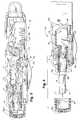
- FIG. 1 is a cross sectional view of the firstembodiment of a lancet actuator device in accordance withthe present invention;
- FIGS. 2 and 3 are sectional views similar toFIG. 1 illustrating sequential operating positions of theactuator mechanism of the device;
- FIG. 4 is a fragmentary sectional view similarto FIGS. 1-3 and illustrating removal of a lancet unitfrom the device;
- FIG. 5 is an exploded perspective view of theactuator mechanism of the device in FIGS. 1-4;
- FIGS. 6 and 7 are enlarged, fragmentary viewsof the reversible sequences of pivoting cam structurewithin the actuator mechanism shown in FIGS. 1-5.
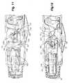
- FIG. 8 is an exploded perspective view of asecond embodiment of an actuator mechanism in accordancewith the present invention;
- FIG. 9 is a partial sectional view from aboveillustrating the assembled actuator mechanism of FIG. 8;
- FIG. 10 is a vertical sectional view of theactuator mechanism shown in FIGS. 8 and 9; and
- FIGS. 11 and 12 are fragmentary views similarto FIG. 10 illustrating sequential operating positionsof the actuator mechanism shown in FIGS. 8-10.
- Referring initially to FIGS. 4 and 6, anembodiment of a lancet actuator in accordance with thepresent invention is generally designated by
referencecharacter 10. Theactuator 10 accommodates the use ofconventional, disposable lancet needle-and-support-bodyunits A. The units A comprise ametal needle 11 carriedby a molded plastic body B. A lancet unit A is insertedinto a lancet holder or carriage means 12 within theactuator 10, as more fully described hereinafter, priorto operation of theactuator 10 to puncture a patient'stissue in a blood sample extraction procedure, afterwhich the lancet unit A is removed from the holder orcarriage 12 for disposal. In theactuator 10 of theillustrated embodiment, a split housing 13 (one halfonly shown) has an access andoperation aperture 13aformed at one end, through which the disposable lancetunit A is inserted and removed. Theactuator 10 alsohas acap 15 which is snap-fitted to thehousing 13 tocover theaperture 13a and the inserted lancet unit Aduring the blood extraction procedure, and thereforethecap 15 will be exposed to the blood sample and willconsequently be disposable with the used lancet unit A.Thecap 15 includes an opening 15a through which theneedle 11 of lancet A can project. The extension ofthecap 15 determines the length of the projection oftheneedle portion 11 therefrom, and therefore alsodetermines the puncture depth when thecap 15 is seatedon the donor's skin. - FIG. 4 illustrates the mechanism of the
actuator 10 preparatory to insertion of the lancetunit A and before the actuating mechanism has beencocked to prepare the actuator for operation. As can be appreciated, this condition of theactuator 10 alsocorresponds to that as would occur after completionof a prior procedure. Thus, the lancet unit A ispositioned within the carriage orholder 12 and thecap 15 is snapped into place. The actuator is thencocked to arrive at the position shown in FIG. 1, asexplained more fully hereinafter, and is thus readyfor operation. - In operation of the
actuator 10, thelancetholder 12 carries the lancet unit A from the retractedposition shown in FIG. 1 to the linearly advancedposition shown in FIG. 2 in which thelancet needle 11projects from theopening 16 to puncture the tissue,and then immediately retracts the lancet unit A into theposition shown in FIG. 3. FIGS. 1, 3 and 4 illustratethe same retracted position of theholder 12, althoughFIG. 4 also shows thecap 15 detached and lancet unit Aremoved from theholder 12. The advancement andretraction of the lancet needle is not only linear, butis attained with a rapid, smooth movement to minimizepatient discomfort. - In the illustrated embodiment, the lancetholder-
carriage 12 is integrally molded and connectedwith a cam-followingstructure 14 which transmitspropulsion to theholder 12 for the advancement of thelancet unit A andneedle 11. A pivoting,drive camstructure 16 has acam arm 17 which is engagable withthe cam-followingstructure 14 in a wiping, cam actionto propel the linear advancement of the cam-followingstructure 14 and holder 12 for the needle puncturingmotion. The cam-followingstructure 14 has apropulsioncam surface 18 which is translated by the propellingclockwise pivot of thedrive cam structure 16 and arm 17 (FIG. 6) between the position in FIG. 1 and theposition in FIG. 2. The cam-followingstructure 14also has a cockingcam surface 20 against which thecam arm 17 is engaged as thecam arm 17 continues inclockwise rotation from the position of FIG. 2 to theposition of FIG. 3 when the cam-followingstructure 14andholder 12 are retracted in reverse motion alongthe highly linear path and thelancet needle 11 iswithdrawn from the tissue puncture. In the terminalposition of holder advancement and needle penetrationof FIG. 2,arm 17 is engaged with an arcuate,apexsurface 21 which medially joins the propulsion andcockingcam surfaces - The clockwise rotation of the
drive camstructure 16 andarm 17 is driven by a torsion springgenerally designated byreference character 22 whichis wound around ahub portion 24 of thedrive camstructure 16. Thehub portion 24 is journaled on astationarypivot bearing pin 26 which projects inwardlyfrom thehousing half 14 as shown in FIGS. 1-4. Thecam arm 17 has aslot 19 which receives themovableend 28 of thetorsion spring 22 so that theend 28bears against and drives the clockwise rotation ofthe arm 17 (and the needle advancement stroke) as thetorsion spring 22 unwinds. In addition, the advancementstroke of the cam-followingstructure 14 andholder 12also compresses acoil spring 30 which surrounds theforward portion of theholder 12; as best shown bycomparison of FIGS. 1 and 2, thestationary end 31of thespring 30 is seated on anannular shoulder 32formed by thehousing halves 14, and themovable springend 33 is secured to anannular shoulder 34 formed onthe exterior and midway along theholder 12. Thecompression of thespring 30 produced by the advancement of theholder 12 is then releasable with expansion toprovide the propulsion of the retraction stroke of theholder 12 as thedrive cam arm 17 slides past thearcuate, apex surface 21 (which medially joinssurfaces 18 and 20) and begins to slide against thecocking camsurface 20 as thecam arm 17 continues the clockwisepivot driven by thetorsion spring 22. As a result, theexpansion of thereturn spring 30 provides a smoothlycontinuous retraction of theholder 12 immediatelyfollowing its advancement so that the puncturing thrustof thelancet needle 11 is rapidly reversed on the samehighly linear path which suppresses patient discomfort. - When the lancet puncture procedure iscompleted with full retraction of the
holder 12 intothe position shown in FIG. 3, the used lancet unit Ais ejected from theholder 12 by manually sliding thecocking structure 36 forwardly to the left from itsneutral position as shown in FIG. 3 into the forwardposition shown in FIG. 4 so that theejector arm 38enters and passes through theslot 40 formed throughthe rear end of theholder 12. Theejector arm 38thereby engages and displaces the lancet body B forremoval through the entrance of theholder 12. Thecocking structure 36 is then manually retracted to theneutral position shown in FIG. 3 so that theejectorarm 38 is withdrawn from theslot 40, after which anew lancet unit A can be inserted into theholder 12.Theejector arm 38 is arranged in laterally offsetlongitudinal alignment in relation to thecam surfaces - After installing the new lancet unit A, andpreparatory to the next blood sampling procedure, the
actuator 10 remains in the position shown in FIG. 3 and must be armed in a cocking operation to achieve theposition shown in FIG. 1 in readiness for a succeedinglancing procedure. In this regard, the lancet can beinstalled either before or after the unit is cocked. Inthe arming or cocking operation, thecocking structure 36 is slidably displaced rearwardly to the right fromthe position shown in FIG. 3 so that thecocking arm 42thereof is moved into engagement with a transverselyprojecting cockingpin 44 extending from thedrive camstructure 16 below thecam arm 17. Continued manualmotion of thecocking structure 36 causes the engagementwith the cockingpin 44 to pivot thedrive cam structure 16 counterclockwise so that thecam arm 17 movesdownwardly from the position shown in FIG. 3 to theposition shown in FIG. 1. As a result, thetorsionspring end 28 is pivoted with thecam arm 17 windingand energizing of thetorsion spring 22; when thecounterclockwise, cocking pivot of thedrive camstructure 16 reaches the position shown in FIG. 1,the end of thepivotal latch structure 46 drops intoengagement behind alatch foot 48 radially projectingfrom thedrive cam structure 16 and the tension inthewound torsion spring 22 maintains the latchingengagement of thefoot 48 against thelatch 46.Thereafter, thereturn spring 50 which was compressedby the rearward motion of the cockingstructure 36expands to return the manually releasedcockingstructure 36 once again to the neutral position shownin FIG. 3. - During the arming or cocking operation shownin FIG. 7, the counterclockwise
pivoting cam arm 17engages the cockingsurface 20 so that the entirecam-followingstructure 14 andholder 12 are drivenin linear advancement similar to the primary lancing advancement thereof. However, the cockingsurface 20forms a larger angle of approximately 45° relative tovertical in comparison with the corresponding angleof approximately 30° formed by thepropulsion surface 18, in order to minimize the initial cocking strainmanually required to wind thetorsion spring 22 andpromote uniformity of the manual cocking load whichadds compression ofcoil return spring 30 to the windingoftorsion spring 22. In addition, the contour ofparticularlycam surface 18 can be variably fabricatedto enable uniform speed of theholder 12 advance andneedle thrust. - When the arming or cocking operation has beencompleted as shown in FIG. 1, the
cam arm 17 is slightlyspaced from thepropulsion cam surface 18 to ensurethat the integral cam-followingstructure 14 andholder 12, and theneedle 11, are fully retracted under thebias of the expandedspring 30. In order to actuatethe lancing procedure and release the propulsion of theholder advancement, thetrigger structure 52 is manuallydepressed inwardly as shown in FIG. 2 causing pivot ofthelatch end 46 so that it disengages from thecamfoot 48 on thedrive cam structure 16 which then pivotscounterclockwise into engagement with thepropulsioncam surface 18 as described hereinabove, under theforce of the unwindingtorsion spring 22. When thesurface of thecap 15 has been placed against thedonor's skin, the cam-driven advancement of theholder 12 thrusts thelancet needle 11 through thecap opening 16 to puncture the skin in the actuator position ofFIG. 2 showing the maximum advancement correspondingto the maximum skin puncture depth. In order to ensurethe accurately linear longitudinal path during theadvancement and smooth retraction of theholder 12 and lancet unit A, theholder 12 and integral cam-followingstructure 14 are provided with laterally projecting andlongitudinally extendingguide flanges slots 55 and 57 (or guide flanges) formed in the housinghalves (13). The guide flanges 54 and 56 andslots holder 12against any slight transverse torque components whichcould be generated by the wiping pivot of thecam arm 17against the cam surfaces 18 and 20 of the cam-followingstructure 14. Consequently, the stabilized and guidedholder 12 does not experience any lateral motion so thatthelancet needle 11 enters and withdraws from the skinin smoothly continuous motions suppressing penetrationtrauma and donor discomfort. - Referring now to Figs. 8-12, a secondembodiment of the actuator in accordance with thepresent invention is generally designated by
referencecharacter 100; additional reference characters of thesecond actuator embodiment generally correspond tosimilar reference characters and features of thefirstembodiment 10. - In the
actuator 100, thereturn spring 130is a torsion spring which is wound and carried on thecam-followingstructure 114. The wound portion of thetorsion spring 130 is inserted betweenretainer arms 170laterally projecting from the side of the cam-followingstructure 114. The two linearly projecting ends 131 ofthetorsion spring 130 respectively bear against upperand lower bearing pins 132 internally projecting fromthehousing half 113 as best shown in Figs. 9 and 10.In operation of thetorsion return spring 130, as bestshown in Figs. 11 and 12, the linearly projecting ends 131 of thespring 130 extend in generally verticalconfiguration as thecam arm 117 begins engagementagainst thepropulsion surface 118 of the cam-followingstructure 140 as the advancement of theholder 120is initiated as shown in Fig. 11. As the advancementof the cam-followingstructure 140 andholder 120progresses, the wound portion of thetorsion spring 130is correspondingly carried forward on the cam-followingstructure 140; however, the stationary bearing pins 133on thehousing 113 cause the linear spring ends 131 topivot and flex in angular configuration C in Fig. 12as thecam arm 17 reaches engagement against themedialcam surface 121 at the terminal position of holderadvancement and needle penetration 111. Thereafter,the further pivot of thecam arm 117 in withdrawalfrom the cockingcam surface 120 allows release of theflexure in the spring ends 131 to drive the retractionof theholder 120 as theends 131 return to thegenerally vertical configuration at the completion ofthe withdrawal stroke. The reverse pivoting of thecam arm 117 during the cocking operation, correspondingto the description of thefirst actuator embodiment 10, also produces flexure of the spring ends 131 insimilar manner. Ashoulder 172 formed on theholder 120 provides a positive stop against thehousing 113to limit forward travel of theholder 112. - With the compact mounting of the
spring 130on the cam-followingstructure 114, theholder 112 canbe provided withguide flanges 154 which laterallyproject adjacent to the forward end of theholder 112and theguide flanges 54 are slidably displaceablethrough correspondingslots 155 forwardly located in thehousing halves (113) adjacent to theoperation aperture 113a. Theguide flanges 154 provide additional axially symmetrical balance as well as extending the accuracy ofthe linear guidance particularly as theholder 112 is intransition from advancement to retraction. Thelateralguide flanges 156 slide throughcorresponding slots 157in the housing halves and guideribs 158 upstandingfrom theflanges 156 ride against theupper slot walls 160 of the corresponding housing halves for additionaltransverse stabilization of the axial motion, to reducepatient discomfort. - While particular embodiments of the presentinvention have been described herein, it will beobvious to those skilled in the art that changes andmodifications in various aspects may be made.Consequently, the scope of the invention is notlimited by any particular embodiment but is definedby the appended claims.
Claims (9)
- An actuating mechanism (10,100) for sequentially advancing andretracting a lancet needle (11,111), comprising:- a housing (13) containing carriagemeans (12,112) for advancement and retraction of the lancet needle and camfollowing means (14,114) for transmitting propulsion forces to said carriage means(12,112) to attain said advancement, said actuating mechanism (10,100) includingdrive cam structure (16,116) engageable with said cam-following means (14,114) fordirecting said propulsion force thereagainst, and- spring structure (22,122) disposed for energy storage and generation of saidpropulsion force directed by said drive cam structure (16,116), and arranged to initiatesaid directed propulsion force and advancement of said carriage means (12, 112);CHARACTERIZED BY: said drive cam structure (16, 116) and said cam following means(14, 114) being not linked, and guide flanges (54, 56) on said carriage means (12, 112) and said camfollowing means (14, 114) and slots (55, 57) in the housing (13) which receive theguide flanges (54,56) such that said flanges (54, 56) are slidably displaceable in theslots (55, 57) furthering the linearization of the advancement of said carriage means(12,112).
- An actuating mechanism according to claim 1 CHARACTERIZED BY:cocking structure (36,136) arranged for energizing said spring structure(22,122) for repetitive operations of said actuating mechanism (10,110) withreplaceable lancet needles (11,111).
- An actuating mechanism according to claim 1 CHARACTERIZED INTHAT said drive cam structure (16,116) pivots reversibly enabling said direction ofsaid propulsion force against said cam following means (14,114) during forward pivotthereof, and reverse pivot thereof to reset said drive cam structure for a subsequentforward pivot in a repetitive operation of said actuating mechanism with a replacementlancet needle.
- An actuating mechanism according to claim 3 CHARACTERIZED BY:cocking structure (36,136) arranged for energizing said spring structure (22,122)wherein said cocking structure energizes said spring structure during saidreverse pivot of said drive cam structure.
- An actuating mechanism according to claim 2 CHARACTERIZED INTHAT said spring structure (22,122) comprises a drive spring structurearranged for energizing by said cocking structure (36, 136).
- An actuating mechanism according to claim 6 CHARACTERIZED INTHAT said drive cam structure (16,116) reversibly pivots in direction forwardlyduring said propulsion and reversely during said energizing of said drive springstructure (22,122) by said cocking structure (36,136).
- An actuating mechanism according to claim 1 CHARACTERIZED BY:return spring structure (30,130) disposed separate from said spring structure(22,122) and arranged to propel said retraction of said carriage means (12, 112)separately from said advancement propulsion by said drive cam structure (16, 116).
- An actuating mechanism according to claim 7 CHARACTERIZED [NTHAT said return spring structure (30, 130) comprises energy transfer and storagemeans for converting a portion of energy generated by said carriage meansadvancement and propulsion to potential energy releasable for propelling said carriagemeans retraction.
- An actuating mechanism according to claim 8 CHARACTERIZED 1NTHAT said spring means (30,130) is energized by said advancement propulsion.
Applications Claiming Priority (2)
| Application Number | Priority Date | Filing Date | Title |
|---|---|---|---|
| US07/878,736US5318583A (en) | 1992-05-05 | 1992-05-05 | Lancet actuator mechanism |
| US878736 | 1992-05-05 |
Publications (2)
| Publication Number | Publication Date |
|---|---|
| EP0569124A1 EP0569124A1 (en) | 1993-11-10 |
| EP0569124B1true EP0569124B1 (en) | 2000-05-31 |
Family
ID=25372724
Family Applications (1)
| Application Number | Title | Priority Date | Filing Date |
|---|---|---|---|
| EP93302444AExpired - LifetimeEP0569124B1 (en) | 1992-05-05 | 1993-03-29 | Improved lancet actuator |
Country Status (7)
| Country | Link |
|---|---|
| US (1) | US5318583A (en) |
| EP (1) | EP0569124B1 (en) |
| JP (1) | JP2688800B2 (en) |
| AU (1) | AU655391B2 (en) |
| CA (1) | CA2093081C (en) |
| DE (1) | DE69328752T2 (en) |
| ES (1) | ES2145761T3 (en) |
Cited By (2)
| Publication number | Priority date | Publication date | Assignee | Title |
|---|---|---|---|---|
| US7691071B2 (en) | 2001-01-19 | 2010-04-06 | Panasonic Corporation | Lancet-integrated sensor, measurer for lancet-integrated sensor, and cartridge |
| US9844330B2 (en) | 2004-11-30 | 2017-12-19 | Becton, Dickinson And Company | Lancet device |
Families Citing this family (188)
| Publication number | Priority date | Publication date | Assignee | Title |
|---|---|---|---|---|
| CA2079192C (en)* | 1992-09-25 | 1995-12-26 | Bernard Strong | Combined lancet and multi-function cap and lancet injector for use therewith |
| CA2551185C (en)* | 1994-03-28 | 2007-10-30 | Sdgi Holdings, Inc. | Apparatus and method for anterior spinal stabilization |
| US5527334A (en)* | 1994-05-25 | 1996-06-18 | Ryder International Corporation | Disposable, retractable lancet |
| US5476474A (en)* | 1994-07-27 | 1995-12-19 | Ryder International Corporation | Rotary lancet |
| US7666150B2 (en)* | 1996-05-17 | 2010-02-23 | Roche Diagnostics Operations, Inc. | Blood and interstitial fluid sampling device |
| EP1579814A3 (en) | 1996-05-17 | 2006-06-14 | Roche Diagnostics Operations, Inc. | Methods and apparatus for sampling and analyzing body fluid |
| US6015392A (en)* | 1996-05-17 | 2000-01-18 | Mercury Diagnostics, Inc. | Apparatus for sampling body fluid |
| US20020010406A1 (en) | 1996-05-17 | 2002-01-24 | Douglas Joel S. | Methods and apparatus for expressing body fluid from an incision |
| US7828749B2 (en) | 1996-05-17 | 2010-11-09 | Roche Diagnostics Operations, Inc. | Blood and interstitial fluid sampling device |
| EP1862116A3 (en)* | 1996-05-17 | 2009-02-25 | Roche Diagnostics Operations, Inc. | Disposable element for use in a body fluid sampling device |
| US5951492A (en)* | 1996-05-17 | 1999-09-14 | Mercury Diagnostics, Inc. | Methods and apparatus for sampling and analyzing body fluid |
| US5951493A (en)* | 1997-05-16 | 1999-09-14 | Mercury Diagnostics, Inc. | Methods and apparatus for expressing body fluid from an incision |
| US6332871B1 (en) | 1996-05-17 | 2001-12-25 | Amira Medical | Blood and interstitial fluid sampling device |
| US7235056B2 (en) | 1996-05-17 | 2007-06-26 | Amira Medical | Body fluid sampling device and methods of use |
| US5984940A (en)* | 1997-05-29 | 1999-11-16 | Atrion Medical Products, Inc. | Lancet device |
| US5948695A (en)* | 1997-06-17 | 1999-09-07 | Mercury Diagnostics, Inc. | Device for determination of an analyte in a body fluid |
| US5938679A (en)* | 1997-10-14 | 1999-08-17 | Hewlett-Packard Company | Apparatus and method for minimally invasive blood sampling |
| US6706000B2 (en) | 1997-11-21 | 2004-03-16 | Amira Medical | Methods and apparatus for expressing body fluid from an incision |
| US5964718A (en)* | 1997-11-21 | 1999-10-12 | Mercury Diagnostics, Inc. | Body fluid sampling device |
| US5971941A (en)* | 1997-12-04 | 1999-10-26 | Hewlett-Packard Company | Integrated system and method for sampling blood and analysis |
| US6071294A (en)* | 1997-12-04 | 2000-06-06 | Agilent Technologies, Inc. | Lancet cartridge for sampling blood |
| US6036924A (en)* | 1997-12-04 | 2000-03-14 | Hewlett-Packard Company | Cassette of lancet cartridges for sampling blood |
| US5871494A (en)* | 1997-12-04 | 1999-02-16 | Hewlett-Packard Company | Reproducible lancing for sampling blood |
| JP2001527216A (en) | 1997-12-19 | 2001-12-25 | アミラ メディカル | Embossed test strip system |
| US6949111B2 (en) | 1998-02-13 | 2005-09-27 | Steven Schraga | Lancet device |
| US6391005B1 (en) | 1998-03-30 | 2002-05-21 | Agilent Technologies, Inc. | Apparatus and method for penetration with shaft having a sensor for sensing penetration depth |
| US6139562A (en) | 1998-03-30 | 2000-10-31 | Agilent Technologies, Inc. | Apparatus and method for incising |
| US6086545A (en)* | 1998-04-28 | 2000-07-11 | Amira Medical | Methods and apparatus for suctioning and pumping body fluid from an incision |
| CA2287757A1 (en) | 1999-10-29 | 2001-04-29 | Medical Plastic Devices M.P.D. Inc. | Disposable lancet |
| US8814896B2 (en) | 1999-11-02 | 2014-08-26 | Stat Medical Devices, Inc. | Single use lancet assembly |
| US20050070945A1 (en)* | 1999-11-02 | 2005-03-31 | Steven Schraga | Single use lancet assembly |
| US6322575B1 (en)* | 2000-01-05 | 2001-11-27 | Steven Schraga | Lancet depth adjustment assembly |
| US6706159B2 (en) | 2000-03-02 | 2004-03-16 | Diabetes Diagnostics | Combined lancet and electrochemical analyte-testing apparatus |
| DE10010694A1 (en)* | 2000-03-04 | 2001-09-06 | Roche Diagnostics Gmbh | Lancet including tipped needle with body surrounding tip |
| US6607543B2 (en)* | 2000-06-13 | 2003-08-19 | Bayer Corporation | Lancing mechanism |
| US6358265B1 (en) | 2000-07-18 | 2002-03-19 | Specialized Health Products, Inc. | Single-step disposable safety lancet apparatus and methods |
| US8641644B2 (en) | 2000-11-21 | 2014-02-04 | Sanofi-Aventis Deutschland Gmbh | Blood testing apparatus having a rotatable cartridge with multiple lancing elements and testing means |
| DE10057832C1 (en)* | 2000-11-21 | 2002-02-21 | Hartmann Paul Ag | Blood analysis device has syringe mounted in casing, annular mounting carrying needles mounted behind test strip and being swiveled so that needle can be pushed through strip and aperture in casing to take blood sample |
| WO2002056751A2 (en) | 2001-01-22 | 2002-07-25 | Roche Diagnostics Gmbh | Lancet device having capillary action |
| DE10121883A1 (en) | 2001-05-05 | 2002-11-07 | Roche Diagnostics Gmbh | Blood Collection system |
| US20020188223A1 (en)* | 2001-06-08 | 2002-12-12 | Edward Perez | Devices and methods for the expression of bodily fluids from an incision |
| US8337419B2 (en) | 2002-04-19 | 2012-12-25 | Sanofi-Aventis Deutschland Gmbh | Tissue penetration device |
| US9226699B2 (en) | 2002-04-19 | 2016-01-05 | Sanofi-Aventis Deutschland Gmbh | Body fluid sampling module with a continuous compression tissue interface surface |
| US7041068B2 (en) | 2001-06-12 | 2006-05-09 | Pelikan Technologies, Inc. | Sampling module device and method |
| US9795747B2 (en) | 2010-06-02 | 2017-10-24 | Sanofi-Aventis Deutschland Gmbh | Methods and apparatus for lancet actuation |
| WO2002101359A2 (en)* | 2001-06-12 | 2002-12-19 | Pelikan Technologies, Inc. | Integrated blood sampling analysis system with multi-use sampling module |
| US7981056B2 (en) | 2002-04-19 | 2011-07-19 | Pelikan Technologies, Inc. | Methods and apparatus for lancet actuation |
| US9427532B2 (en) | 2001-06-12 | 2016-08-30 | Sanofi-Aventis Deutschland Gmbh | Tissue penetration device |
| US7001344B2 (en)* | 2001-06-12 | 2006-02-21 | Pelikan Technologies, Inc. | Blood sampling device with diaphragm actuated lancet |
| EP1395185B1 (en) | 2001-06-12 | 2010-10-27 | Pelikan Technologies Inc. | Electric lancet actuator |
| JP4209767B2 (en) | 2001-06-12 | 2009-01-14 | ペリカン テクノロジーズ インコーポレイテッド | Self-optimized cutting instrument with adaptive means for temporary changes in skin properties |
| JP4272051B2 (en) | 2001-06-12 | 2009-06-03 | ペリカン テクノロジーズ インコーポレイテッド | Blood sampling apparatus and method |
| US7344507B2 (en) | 2002-04-19 | 2008-03-18 | Pelikan Technologies, Inc. | Method and apparatus for lancet actuation |
| AU2002344825A1 (en) | 2001-06-12 | 2002-12-23 | Pelikan Technologies, Inc. | Method and apparatus for improving success rate of blood yield from a fingerstick |
| US7749174B2 (en) | 2001-06-12 | 2010-07-06 | Pelikan Technologies, Inc. | Method and apparatus for lancet launching device intergrated onto a blood-sampling cartridge |
| EP1408852A4 (en) | 2001-06-13 | 2009-09-09 | Steven Schraga | Single use lancet device |
| US8048097B2 (en)* | 2001-08-14 | 2011-11-01 | Steven Schraga | Single use lancet assembly |
| US6918918B1 (en) | 2001-08-14 | 2005-07-19 | Steven Schraga | Single use lancet assembly |
| US7264627B2 (en)* | 2001-08-29 | 2007-09-04 | Roche Diagnostics Operations, Inc. | Wicking methods and structures for use in sampling bodily fluids |
| DE10142232B4 (en) | 2001-08-29 | 2021-04-29 | Roche Diabetes Care Gmbh | Process for the production of an analytical aid with a lancet and test element |
| US20040229347A1 (en)* | 2001-09-17 | 2004-11-18 | Perez Edward P. | Embossed test strip system |
| CA2461370A1 (en) | 2001-09-26 | 2003-05-15 | F. Hoffmann-La Roche Ag | Method and apparatus for sampling bodily fluid |
| US7344894B2 (en) | 2001-10-16 | 2008-03-18 | Agilent Technologies, Inc. | Thermal regulation of fluidic samples within a diagnostic cartridge |
| DE20213607U1 (en) | 2002-02-21 | 2003-07-03 | Paul Hartmann AG, 89522 Heidenheim | Blood analyzer for the determination of an analyte |
| US8372016B2 (en) | 2002-04-19 | 2013-02-12 | Sanofi-Aventis Deutschland Gmbh | Method and apparatus for body fluid sampling and analyte sensing |
| US7524293B2 (en) | 2002-04-19 | 2009-04-28 | Pelikan Technologies, Inc. | Method and apparatus for penetrating tissue |
| US7976476B2 (en) | 2002-04-19 | 2011-07-12 | Pelikan Technologies, Inc. | Device and method for variable speed lancet |
| US7648468B2 (en) | 2002-04-19 | 2010-01-19 | Pelikon Technologies, Inc. | Method and apparatus for penetrating tissue |
| US7491178B2 (en) | 2002-04-19 | 2009-02-17 | Pelikan Technologies, Inc. | Method and apparatus for penetrating tissue |
| US8784335B2 (en) | 2002-04-19 | 2014-07-22 | Sanofi-Aventis Deutschland Gmbh | Body fluid sampling device with a capacitive sensor |
| US9795334B2 (en) | 2002-04-19 | 2017-10-24 | Sanofi-Aventis Deutschland Gmbh | Method and apparatus for penetrating tissue |
| US7229458B2 (en) | 2002-04-19 | 2007-06-12 | Pelikan Technologies, Inc. | Method and apparatus for penetrating tissue |
| US8360992B2 (en) | 2002-04-19 | 2013-01-29 | Sanofi-Aventis Deutschland Gmbh | Method and apparatus for penetrating tissue |
| US7563232B2 (en) | 2002-04-19 | 2009-07-21 | Pelikan Technologies, Inc. | Method and apparatus for penetrating tissue |
| US7547287B2 (en) | 2002-04-19 | 2009-06-16 | Pelikan Technologies, Inc. | Method and apparatus for penetrating tissue |
| US8221334B2 (en) | 2002-04-19 | 2012-07-17 | Sanofi-Aventis Deutschland Gmbh | Method and apparatus for penetrating tissue |
| US7717863B2 (en) | 2002-04-19 | 2010-05-18 | Pelikan Technologies, Inc. | Method and apparatus for penetrating tissue |
| US7371247B2 (en) | 2002-04-19 | 2008-05-13 | Pelikan Technologies, Inc | Method and apparatus for penetrating tissue |
| US8579831B2 (en) | 2002-04-19 | 2013-11-12 | Sanofi-Aventis Deutschland Gmbh | Method and apparatus for penetrating tissue |
| WO2003088824A2 (en)* | 2002-04-19 | 2003-10-30 | Pelikan Technologies, Inc. | Device and method for variable speed lancet |
| US7291117B2 (en) | 2002-04-19 | 2007-11-06 | Pelikan Technologies, Inc. | Method and apparatus for penetrating tissue |
| US7331931B2 (en) | 2002-04-19 | 2008-02-19 | Pelikan Technologies, Inc. | Method and apparatus for penetrating tissue |
| US7901362B2 (en) | 2002-04-19 | 2011-03-08 | Pelikan Technologies, Inc. | Method and apparatus for penetrating tissue |
| US9248267B2 (en) | 2002-04-19 | 2016-02-02 | Sanofi-Aventis Deustchland Gmbh | Tissue penetration device |
| US7232451B2 (en)* | 2002-04-19 | 2007-06-19 | Pelikan Technologies, Inc. | Method and apparatus for penetrating tissue |
| US9314194B2 (en) | 2002-04-19 | 2016-04-19 | Sanofi-Aventis Deutschland Gmbh | Tissue penetration device |
| US7141058B2 (en) | 2002-04-19 | 2006-11-28 | Pelikan Technologies, Inc. | Method and apparatus for a body fluid sampling device using illumination |
| US7485128B2 (en) | 2002-04-19 | 2009-02-03 | Pelikan Technologies, Inc. | Method and apparatus for penetrating tissue |
| US7410468B2 (en) | 2002-04-19 | 2008-08-12 | Pelikan Technologies, Inc. | Method and apparatus for penetrating tissue |
| US7244265B2 (en) | 2002-04-19 | 2007-07-17 | Pelikan Technologies, Inc. | Method and apparatus for penetrating tissue |
| US7582099B2 (en) | 2002-04-19 | 2009-09-01 | Pelikan Technologies, Inc | Method and apparatus for penetrating tissue |
| US7674232B2 (en) | 2002-04-19 | 2010-03-09 | Pelikan Technologies, Inc. | Method and apparatus for penetrating tissue |
| US8267870B2 (en) | 2002-04-19 | 2012-09-18 | Sanofi-Aventis Deutschland Gmbh | Method and apparatus for body fluid sampling with hybrid actuation |
| US7892183B2 (en) | 2002-04-19 | 2011-02-22 | Pelikan Technologies, Inc. | Method and apparatus for body fluid sampling and analyte sensing |
| US7708701B2 (en) | 2002-04-19 | 2010-05-04 | Pelikan Technologies, Inc. | Method and apparatus for a multi-use body fluid sampling device |
| US7909778B2 (en) | 2002-04-19 | 2011-03-22 | Pelikan Technologies, Inc. | Method and apparatus for penetrating tissue |
| US7374544B2 (en) | 2002-04-19 | 2008-05-20 | Pelikan Technologies, Inc. | Method and apparatus for penetrating tissue |
| US7297122B2 (en) | 2002-04-19 | 2007-11-20 | Pelikan Technologies, Inc. | Method and apparatus for penetrating tissue |
| US8702624B2 (en) | 2006-09-29 | 2014-04-22 | Sanofi-Aventis Deutschland Gmbh | Analyte measurement device with a single shot actuator |
| US20040039407A1 (en)* | 2002-04-29 | 2004-02-26 | Steven Schraga | Lancet device |
| US8715309B2 (en) | 2002-04-29 | 2014-05-06 | Steven Schraga | Lancet device |
| CA2444630A1 (en)* | 2002-10-15 | 2004-04-15 | Bayer Healthcare Llc | Lancing device |
| AU2003290589A1 (en)* | 2002-11-01 | 2004-06-07 | Pelikan Technologies, Inc. | Method and apparatus for body fluid sampling |
| CN100361623C (en)* | 2002-11-01 | 2008-01-16 | 佩利坎技术公司 | Method and device for sampling body fluid |
| US7572237B2 (en) | 2002-11-06 | 2009-08-11 | Abbott Diabetes Care Inc. | Automatic biological analyte testing meter with integrated lancing device and methods of use |
| EP1578270B1 (en)* | 2002-12-24 | 2018-08-01 | Roche Diabetes Care GmbH | A sampling device utilizing biased capillary action |
| US8574895B2 (en) | 2002-12-30 | 2013-11-05 | Sanofi-Aventis Deutschland Gmbh | Method and apparatus using optical techniques to measure analyte levels |
| EP1614382B1 (en)* | 2003-04-11 | 2012-07-11 | ARKRAY, Inc. | Needle insertion device |
| CN100512753C (en)* | 2003-04-11 | 2009-07-15 | 爱科来株式会社 | Needle insertion device |
| JP4296035B2 (en) | 2003-05-21 | 2009-07-15 | アークレイ株式会社 | Puncture device |
| DE602004028463D1 (en) | 2003-05-30 | 2010-09-16 | Pelikan Technologies Inc | METHOD AND DEVICE FOR INJECTING LIQUID |
| US7850621B2 (en) | 2003-06-06 | 2010-12-14 | Pelikan Technologies, Inc. | Method and apparatus for body fluid sampling and analyte sensing |
| WO2006001797A1 (en) | 2004-06-14 | 2006-01-05 | Pelikan Technologies, Inc. | Low pain penetrating |
| EP1635700B1 (en) | 2003-06-13 | 2016-03-09 | Sanofi-Aventis Deutschland GmbH | Apparatus for a point of care device |
| US7510564B2 (en)* | 2003-06-27 | 2009-03-31 | Abbott Diabetes Care Inc. | Lancing device |
| US20190357827A1 (en) | 2003-08-01 | 2019-11-28 | Dexcom, Inc. | Analyte sensor |
| DE10336933B4 (en)* | 2003-08-07 | 2007-04-26 | Roche Diagnostics Gmbh | Blood Collection system |
| JP3100042U (en)* | 2003-08-26 | 2004-04-30 | アルプス電気株式会社 | Television tuner |
| US8282576B2 (en) | 2003-09-29 | 2012-10-09 | Sanofi-Aventis Deutschland Gmbh | Method and apparatus for an improved sample capture device |
| EP1680014A4 (en) | 2003-10-14 | 2009-01-21 | Pelikan Technologies Inc | METHOD AND DEVICE FOR A VARIABLE USER INTERFACE |
| US20080082117A1 (en)* | 2003-11-12 | 2008-04-03 | Facet Technologies, Llc | Lancing device |
| US8221332B2 (en)* | 2003-11-12 | 2012-07-17 | Facet Technologies, Llc | Multi-lancet cartridge and lancing device |
| EP1684634A2 (en)* | 2003-11-12 | 2006-08-02 | Facet Technologies, LLC | Lancing device and multi-lancet cartridge |
| US8668656B2 (en) | 2003-12-31 | 2014-03-11 | Sanofi-Aventis Deutschland Gmbh | Method and apparatus for improving fluidic flow and sample capture |
| US7822454B1 (en) | 2005-01-03 | 2010-10-26 | Pelikan Technologies, Inc. | Fluid sampling device with improved analyte detecting member configuration |
| US20050159768A1 (en)* | 2004-01-15 | 2005-07-21 | Home Diagnostics, Inc. | Lancing device |
| WO2009048462A1 (en) | 2007-10-09 | 2009-04-16 | Dexcom, Inc. | Integrated insulin delivery system with continuous glucose sensor |
| US7377904B2 (en) | 2004-04-16 | 2008-05-27 | Facet Technologies, Llc | Cap displacement mechanism for lancing device and multi-lancet cartridge |
| CN1968651A (en)* | 2004-05-07 | 2007-05-23 | 贝克顿·迪金森公司 | Cam actuated medical piercing device and method |
| US9066688B2 (en) | 2004-05-07 | 2015-06-30 | Becton, Dickinson And Company | Contact activated lancet device |
| KR101121072B1 (en)* | 2004-05-07 | 2012-03-15 | 벡톤 디킨슨 앤드 컴퍼니 | Contact activated lancet device |
| WO2006011062A2 (en) | 2004-05-20 | 2006-02-02 | Albatros Technologies Gmbh & Co. Kg | Printable hydrogel for biosensors |
| US9775553B2 (en) | 2004-06-03 | 2017-10-03 | Sanofi-Aventis Deutschland Gmbh | Method and apparatus for a fluid sampling device |
| WO2005120365A1 (en) | 2004-06-03 | 2005-12-22 | Pelikan Technologies, Inc. | Method and apparatus for a fluid sampling device |
| US8257380B2 (en)* | 2004-06-29 | 2012-09-04 | Stat Medical Devices, Inc. | Adjustabable disposable/single-use lancet device and method |
| US7837633B2 (en) | 2004-06-30 | 2010-11-23 | Facet Technologies, Llc | Lancing device and multi-lancet cartridge |
| US20060030788A1 (en)* | 2004-08-04 | 2006-02-09 | Daniel Wong | Apparatus and method for extracting bodily fluid utilizing a flat lancet |
| US20080119884A1 (en)* | 2004-09-09 | 2008-05-22 | Flora Bruce A | Single Puncture Lancing Fixture with Depth Adjustment and Control of Contact Force |
| EP1841359A1 (en)* | 2004-09-09 | 2007-10-10 | Bayer Healthcare, LLC | Damping system for a lancet using compressed air |
| BRPI0516235A (en)* | 2004-10-21 | 2008-08-26 | Bayer Healthcare Llc | sensor distribution device and sensor extraction mechanism |
| US9788771B2 (en) | 2006-10-23 | 2017-10-17 | Abbott Diabetes Care Inc. | Variable speed sensor insertion devices and methods of use |
| US8652831B2 (en) | 2004-12-30 | 2014-02-18 | Sanofi-Aventis Deutschland Gmbh | Method and apparatus for analyte measurement test time |
| US20060178686A1 (en)* | 2005-02-07 | 2006-08-10 | Steven Schraga | Single use lancet device |
| CN101163446A (en)* | 2005-03-04 | 2008-04-16 | 拜尔保健有限公司 | Lancet-release mechanism |
| US8784444B2 (en)* | 2005-03-04 | 2014-07-22 | Bayer Healthcare Llc | Lancet release mechanism |
| PL2425776T3 (en) | 2005-04-07 | 2013-12-31 | Becton Dickinson Co | Lancet device |
| KR100904106B1 (en)* | 2005-04-28 | 2009-06-24 | 파나소닉 주식회사 | Needle insertion instrument and insertion needle cartridge |
| EP1903927A2 (en)* | 2005-06-30 | 2008-04-02 | Bayer Healthcare, LLC | Single-puncture lancing system |
| US8048098B2 (en)* | 2005-07-14 | 2011-11-01 | Bayer Healthcare Llc | Lancing device for one skin puncture |
| US8617195B2 (en)* | 2005-08-04 | 2013-12-31 | Bayer Healthcare Llc | Lancing device |
| CA2671441C (en)* | 2006-12-01 | 2015-10-20 | Medipurpose Pte Ltd | A device for performing an incision |
| DE102007024181B4 (en)* | 2007-03-05 | 2011-06-16 | Gerresheimer Regensburg Gmbh | Lancing device for blood collection with a leg spring |
| DE102007063661B4 (en)* | 2007-03-05 | 2012-03-15 | Gerresheimer Regensburg Gmbh | Lancing device with torsion spring |
| US8303615B2 (en)* | 2007-03-12 | 2012-11-06 | Bayer Healthcare Llc | Lancet-eject mechanism |
| JP2010521666A (en)* | 2007-03-12 | 2010-06-24 | バイエル・ヘルスケア・エルエルシー | Single sensor meter system that does not require sensor operation and method using the same |
| KR100820523B1 (en)* | 2007-03-14 | 2008-04-08 | 홍관호 | Blood collector |
| WO2009075907A2 (en)* | 2007-07-05 | 2009-06-18 | Facet Technologies, Llc | Multi-lancet cartridge and lancing device |
| GB0715798D0 (en) | 2007-08-14 | 2007-09-19 | Owen Mumford Ltd | Lancing devices |
| DE602007013909D1 (en)* | 2007-10-19 | 2011-05-26 | Bionime Corp | lancing device |
| EP2265324B1 (en) | 2008-04-11 | 2015-01-28 | Sanofi-Aventis Deutschland GmbH | Integrated analyte measurement system |
| US8900193B2 (en) | 2008-12-31 | 2014-12-02 | St. Jude Medical, Atrial Fibrillation Division, Inc. | Fast-acting or rotating transseptal needle |
| US9375169B2 (en) | 2009-01-30 | 2016-06-28 | Sanofi-Aventis Deutschland Gmbh | Cam drive for managing disposable penetrating member actions with a single motor and motor and control system |
| WO2010113527A1 (en) | 2009-04-03 | 2010-10-07 | パナソニック株式会社 | Second-order distortion correcting receiver and second-order distortion correcting method |
| US9517027B2 (en)* | 2009-07-10 | 2016-12-13 | Facet Techonologies, Llc | Advancement mechanism for cartridge-based devices |
| DK3689237T3 (en) | 2009-07-23 | 2021-08-16 | Abbott Diabetes Care Inc | Method of preparation and system for continuous analyte measurement |
| EP3001194B1 (en) | 2009-08-31 | 2019-04-17 | Abbott Diabetes Care, Inc. | Medical devices and methods |
| US8965476B2 (en) | 2010-04-16 | 2015-02-24 | Sanofi-Aventis Deutschland Gmbh | Tissue penetration device |
| JP5745837B2 (en)* | 2010-12-24 | 2015-07-08 | オリンパス株式会社 | Treatment tool |
| JP5948256B2 (en)* | 2011-02-14 | 2016-07-06 | 株式会社旭ポリスライダー | Lancet device |
| EP2697650B1 (en) | 2011-04-15 | 2020-09-30 | Dexcom, Inc. | Advanced analyte sensor calibration and error detection |
| WO2013070488A1 (en)* | 2011-11-08 | 2013-05-16 | Facet Technologies, Llc | Lancing device with cam-actuated drive and separate guidance |
| US10085681B2 (en) | 2012-04-11 | 2018-10-02 | Facet Technologies, Llc | Lancing device with moving pivot depth adjust |
| EP2836125B1 (en) | 2012-04-12 | 2016-06-08 | Facet Technologies, LLC | Lancing device with side activated charge and eject mechanisms |
| JP6313769B2 (en)* | 2012-09-27 | 2018-04-18 | ファセット テクノロジーズ エルエルシーFacet Technologies, LLC | Depth adjustment mechanism for puncture device |
| WO2014083783A1 (en) | 2012-11-30 | 2014-06-05 | パナソニックヘルスケア株式会社 | Puncture instrument, puncture needle cartridge mounted in puncture instrument, and method for using puncture instrument and puncture needle cartridge |
| JP6640830B2 (en) | 2014-07-18 | 2020-02-05 | ベクトン・ディキンソン・アンド・カンパニーBecton, Dickinson And Company | Lancet device for removing first droplet |
| EP4026488B1 (en) | 2015-12-30 | 2023-07-19 | Dexcom, Inc. | Transcutaneous analyte sensor systems and methods |
| USD806246S1 (en) | 2016-02-25 | 2017-12-26 | Steven Schraga | Lancet cover |
| US11071478B2 (en) | 2017-01-23 | 2021-07-27 | Abbott Diabetes Care Inc. | Systems, devices and methods for analyte sensor insertion |
| EP3618712A1 (en) | 2017-05-03 | 2020-03-11 | Abbott Diabetes Care Inc. | Systems, devices, and methods with duration-based adjustment of sensor data |
| EP4111949B1 (en) | 2017-06-23 | 2023-07-26 | Dexcom, Inc. | Transcutaneous analyte sensors, applicators therefor, and needle hub comprising anti-rotation feature |
| US20190120785A1 (en) | 2017-10-24 | 2019-04-25 | Dexcom, Inc. | Pre-connected analyte sensors |
| US11331022B2 (en) | 2017-10-24 | 2022-05-17 | Dexcom, Inc. | Pre-connected analyte sensors |
| US11918348B2 (en) | 2017-12-05 | 2024-03-05 | Abbott Diabetes Care Inc. | Medical devices having a dynamic surface profile and methods for production and use thereof |
| EP4218567B1 (en) | 2018-06-07 | 2025-03-12 | Abbott Diabetes Care, Inc. | Focused sterilization and sterilized sub-assemblies for analyte monitoring systems |
| CN112423664B (en) | 2018-06-07 | 2025-01-21 | 雅培糖尿病护理公司 | Focused sterilization and sterilized sub-assemblies for analyte monitoring systems |
| USD926325S1 (en) | 2018-06-22 | 2021-07-27 | Dexcom, Inc. | Wearable medical monitoring device |
| CA3188510A1 (en) | 2020-08-31 | 2022-03-03 | Vivek S. RAO | Systems, devices, and methods for analyte sensor insertion |
Family Cites Families (9)
| Publication number | Priority date | Publication date | Assignee | Title |
|---|---|---|---|---|
| US2061A (en)* | 1841-04-24 | Spring-lancet | ||
| DE3011211A1 (en)* | 1980-03-22 | 1981-10-01 | Clinicon Mannheim GmbH, 6800 Mannheim | BLOOD PLANT DEVICE FOR TAKING BLOOD FOR DIAGNOSTIC PURPOSES |
| US4628929A (en)* | 1985-08-16 | 1986-12-16 | American Hospital Supply Corporation | Retractable blade bleeding time device |
| JPS62137195A (en)* | 1985-12-10 | 1987-06-20 | Sanko Kagaku Kk | Flux composition for solder |
| US4924879A (en)* | 1988-10-07 | 1990-05-15 | Brien Walter J O | Blood lancet device |
| US4895147A (en)* | 1988-10-28 | 1990-01-23 | Sherwood Medical Company | Lancet injector |
| US5035704A (en)* | 1989-03-07 | 1991-07-30 | Lambert Robert D | Blood sampling mechanism |
| US5196025A (en)* | 1990-05-21 | 1993-03-23 | Ryder International Corporation | Lancet actuator with retractable mechanism |
| JP2539535B2 (en)* | 1990-07-06 | 1996-10-02 | 株式会社日立製作所 | Positioning satellite received signal processing method and apparatus and navigation system |
- 1992
- 1992-05-05USUS07/878,736patent/US5318583A/ennot_activeExpired - Lifetime
- 1993
- 1993-03-24AUAU35412/93Apatent/AU655391B2/ennot_activeExpired
- 1993-03-29ESES93302444Tpatent/ES2145761T3/ennot_activeExpired - Lifetime
- 1993-03-29EPEP93302444Apatent/EP0569124B1/ennot_activeExpired - Lifetime
- 1993-03-29DEDE69328752Tpatent/DE69328752T2/ennot_activeExpired - Lifetime
- 1993-03-31CACA002093081Apatent/CA2093081C/ennot_activeExpired - Lifetime
- 1993-05-06JPJP5131300Apatent/JP2688800B2/ennot_activeExpired - Lifetime
Cited By (8)
| Publication number | Priority date | Publication date | Assignee | Title |
|---|---|---|---|---|
| US7691071B2 (en) | 2001-01-19 | 2010-04-06 | Panasonic Corporation | Lancet-integrated sensor, measurer for lancet-integrated sensor, and cartridge |
| US7758517B2 (en) | 2001-01-19 | 2010-07-20 | Panasonic Corporation | Lancet-integrated sensor, measuring device for lancet-integrated sensor, and cartridge |
| US7841993B2 (en) | 2001-01-19 | 2010-11-30 | Panasonic Corporation | Lancet-integrated sensor, measuring device for lancet-integrated sensor, and cartridge |
| US7905843B2 (en) | 2001-01-19 | 2011-03-15 | Panasonic Corporation | Lancet-integrated sensor and measuring device for lancet-integrated sensor |
| US8118756B2 (en) | 2001-01-19 | 2012-02-21 | Panasonic Corporation | Lancet-integrated sensor |
| US8235914B2 (en) | 2001-01-19 | 2012-08-07 | Panasonic Corporation | Measuring device for a lancet-integrated sensor |
| US8551017B2 (en) | 2001-01-19 | 2013-10-08 | Panasonic Corporation | Lancet-integrated sensor, measuring device for lancet-integrated sensor, and cartridge |
| US9844330B2 (en) | 2004-11-30 | 2017-12-19 | Becton, Dickinson And Company | Lancet device |
Also Published As
| Publication number | Publication date |
|---|---|
| JPH067329A (en) | 1994-01-18 |
| JP2688800B2 (en) | 1997-12-10 |
| CA2093081C (en) | 1997-12-23 |
| CA2093081A1 (en) | 1993-11-06 |
| DE69328752D1 (en) | 2000-07-06 |
| US5318583A (en) | 1994-06-07 |
| ES2145761T3 (en) | 2000-07-16 |
| DE69328752T2 (en) | 2001-03-22 |
| AU3541293A (en) | 1993-11-11 |
| AU655391B2 (en) | 1994-12-15 |
| EP0569124A1 (en) | 1993-11-10 |
Similar Documents
| Publication | Publication Date | Title |
|---|---|---|
| EP0569124B1 (en) | Improved lancet actuator | |
| US5196025A (en) | Lancet actuator with retractable mechanism | |
| US5121751A (en) | Instrument for tissue sampling | |
| US7223276B2 (en) | Blood removal system | |
| US5243994A (en) | Instrument for tissue sampling including a carriage assembly | |
| US5645555A (en) | Rotary lancet | |
| US4944308A (en) | Tissue sampling device | |
| US5527334A (en) | Disposable, retractable lancet | |
| EP1415593B1 (en) | Lancing device | |
| US12329524B2 (en) | Latch mechanism for preventing lancet oscillation in a lancing device | |
| NZ507851A (en) | Lancet apparatus having a quick release system for making a narrow incision on the skin | |
| EP2407113A1 (en) | Device for taking at least one sample of tissue | |
| EP2836125B1 (en) | Lancing device with side activated charge and eject mechanisms | |
| CN216724562U (en) | Blood sampling pen | |
| JPH0628663B2 (en) | Biopsy needle device | |
| CN111053586A (en) | Anastomat reset power-assisted mechanism and anastomat | |
| JP2025510406A (en) | Biopsy cancer |
Legal Events
| Date | Code | Title | Description |
|---|---|---|---|
| PUAI | Public reference made under article 153(3) epc to a published international application that has entered the european phase | Free format text:ORIGINAL CODE: 0009012 | |
| AK | Designated contracting states | Kind code of ref document:A1 Designated state(s):DE ES FR GB IT | |
| 17P | Request for examination filed | Effective date:19940505 | |
| RAP1 | Party data changed (applicant data changed or rights of an application transferred) | Owner name:BOEHRINGER MANNHEIM CORPORATION Owner name:RYDER INTERNATIONAL CORPORATION | |
| 17Q | First examination report despatched | Effective date:19951208 | |
| GRAG | Despatch of communication of intention to grant | Free format text:ORIGINAL CODE: EPIDOS AGRA | |
| GRAG | Despatch of communication of intention to grant | Free format text:ORIGINAL CODE: EPIDOS AGRA | |
| GRAH | Despatch of communication of intention to grant a patent | Free format text:ORIGINAL CODE: EPIDOS IGRA | |
| RAP1 | Party data changed (applicant data changed or rights of an application transferred) | Owner name:BOEHRINGER MANNHEIM CORPORATION Owner name:ATRION MEDICAL PRODUCTS, INC. | |
| GRAH | Despatch of communication of intention to grant a patent | Free format text:ORIGINAL CODE: EPIDOS IGRA | |
| RAP1 | Party data changed (applicant data changed or rights of an application transferred) | Owner name:ROCHE DIAGNOSTICS CORPORATION Owner name:ATRION MEDICAL PRODUCTS, INC. | |
| ITF | It: translation for a ep patent filed | ||
| RIC1 | Information provided on ipc code assigned before grant | Free format text:7A 61B 17/32 A | |
| GRAA | (expected) grant | Free format text:ORIGINAL CODE: 0009210 | |
| AK | Designated contracting states | Kind code of ref document:B1 Designated state(s):DE ES FR GB IT | |
| REF | Corresponds to: | Ref document number:69328752 Country of ref document:DE Date of ref document:20000706 | |
| REG | Reference to a national code | Ref country code:ES Ref legal event code:FG2A Ref document number:2145761 Country of ref document:ES Kind code of ref document:T3 | |
| ET | Fr: translation filed | ||
| PLBE | No opposition filed within time limit | Free format text:ORIGINAL CODE: 0009261 | |
| STAA | Information on the status of an ep patent application or granted ep patent | Free format text:STATUS: NO OPPOSITION FILED WITHIN TIME LIMIT | |
| 26N | No opposition filed | ||
| REG | Reference to a national code | Ref country code:GB Ref legal event code:IF02 | |
| PGFP | Annual fee paid to national office [announced via postgrant information from national office to epo] | Ref country code:FR Payment date:20120319 Year of fee payment:20 | |
| PGFP | Annual fee paid to national office [announced via postgrant information from national office to epo] | Ref country code:IT Payment date:20120322 Year of fee payment:20 Ref country code:GB Payment date:20120328 Year of fee payment:20 | |
| PGFP | Annual fee paid to national office [announced via postgrant information from national office to epo] | Ref country code:DE Payment date:20120411 Year of fee payment:20 | |
| PGFP | Annual fee paid to national office [announced via postgrant information from national office to epo] | Ref country code:ES Payment date:20120419 Year of fee payment:20 | |
| REG | Reference to a national code | Ref country code:DE Ref legal event code:R071 Ref document number:69328752 Country of ref document:DE | |
| REG | Reference to a national code | Ref country code:DE Ref legal event code:R071 Ref document number:69328752 Country of ref document:DE | |
| REG | Reference to a national code | Ref country code:GB Ref legal event code:PE20 Expiry date:20130328 | |
| PG25 | Lapsed in a contracting state [announced via postgrant information from national office to epo] | Ref country code:GB Free format text:LAPSE BECAUSE OF EXPIRATION OF PROTECTION Effective date:20130328 | |
| REG | Reference to a national code | Ref country code:ES Ref legal event code:FD2A Effective date:20130718 | |
| PG25 | Lapsed in a contracting state [announced via postgrant information from national office to epo] | Ref country code:ES Free format text:LAPSE BECAUSE OF EXPIRATION OF PROTECTION Effective date:20130330 Ref country code:DE Free format text:LAPSE BECAUSE OF EXPIRATION OF PROTECTION Effective date:20130403 |