EP0567705B1 - Posteriorly stabilized total knee prosthesis - Google Patents
Posteriorly stabilized total knee prosthesisDownload PDFInfo
- Publication number
- EP0567705B1 EP0567705B1EP19920420144EP92420144AEP0567705B1EP 0567705 B1EP0567705 B1EP 0567705B1EP 19920420144EP19920420144EP 19920420144EP 92420144 AEP92420144 AEP 92420144AEP 0567705 B1EP0567705 B1EP 0567705B1
- Authority
- EP
- European Patent Office
- Prior art keywords
- radius
- curvature
- prosthesis
- condyles
- prosthesis according
- Prior art date
- Legal status (The legal status is an assumption and is not a legal conclusion. Google has not performed a legal analysis and makes no representation as to the accuracy of the status listed.)
- Expired - Lifetime
Links
Images


Classifications
- A—HUMAN NECESSITIES
- A61—MEDICAL OR VETERINARY SCIENCE; HYGIENE
- A61F—FILTERS IMPLANTABLE INTO BLOOD VESSELS; PROSTHESES; DEVICES PROVIDING PATENCY TO, OR PREVENTING COLLAPSING OF, TUBULAR STRUCTURES OF THE BODY, e.g. STENTS; ORTHOPAEDIC, NURSING OR CONTRACEPTIVE DEVICES; FOMENTATION; TREATMENT OR PROTECTION OF EYES OR EARS; BANDAGES, DRESSINGS OR ABSORBENT PADS; FIRST-AID KITS
- A61F2/00—Filters implantable into blood vessels; Prostheses, i.e. artificial substitutes or replacements for parts of the body; Appliances for connecting them with the body; Devices providing patency to, or preventing collapsing of, tubular structures of the body, e.g. stents
- A61F2/02—Prostheses implantable into the body
- A61F2/30—Joints
- A61F2/38—Joints for elbows or knees
- A61F2/3886—Joints for elbows or knees for stabilising knees against anterior or lateral dislocations
Definitions
- the present inventionrelates to knee prostheses and it relates, more particularly, to the field of total prostheses.
- linked prosthesesthose involving two complementary parts should be retained which are joined by a material articular system, such as at least one axis, constituting the artificial pivot system, materializing the knee joint, in a direction perpendicular to the sagittal or anteroposterior plane.
- a material articular systemsuch as at least one axis, constituting the artificial pivot system, materializing the knee joint, in a direction perpendicular to the sagittal or anteroposterior plane.
- the second familyknown as free, is that comprising prostheses made up of two elements, respectively adaptable on the lower epiphyses of the femur and upper tibia, to cooperate, by relative sliding, while being maintained in surface contact through , in particular, natural internal and external lateral ligaments, without the presence of articulation links between them.
- the inventionrelates only to the field of so-called free prostheses.
- prosthesescomprising an adaptable femoral element after bone resection on the lower epiphyseal end of the femur and having an anterior part delimiting a femoral trochlea from which extend two separate condyles having a variable curvature in the direction of the rear face.
- a free prosthesisalso comprises, in order to cooperate with the femoral element, an adaptable tibial element after resection on the upper epiphyseal end of the tibia.
- a tibial elementoffers, on the upper surface, a pad presenting two glenoid cavities of cooperation for the condyles and a sort of central edge parallel to the sagittal plane, intended to be inserted in the intercondylar space of the femoral element.
- a prosthesis of the above kindallows a free space to remain between the separated condyles allowing the passage of the cruciate ligaments which are responsible, essentially, for the holding of the tibia relative to the femur in the anteroposterior plane, in a state of flexion in particular.
- the implantation of a total knee prosthesisimplies to remove the cruciate ligaments, due to their deficiency, their disinsertion or their rupture.
- a total prosthesis of the above typethen has, when implanted in such a case, a fundamental functional drawback in the movements involving bending, for example in the case of climbing or descending a staircase or, even , in the case of changing from a sitting position to a standing position of the subject.
- a prosthesis of the above typeis not likely to oppose the drawer movements of the tibia relative to the femur, corresponding to a sliding, generally towards the rear, glenoid cavities of the tibia relative to the condyles.
- Such a drawer movementis traumatic for the lateral ligaments, induces punctual wear of the tibial pad and introduces an imbalance factor for the subject.
- Such prostheseswhich can be illustrated by the teachings of the French patent 2 473 876 (81-01 056) and 2 615 386 (87-07 353), take advantage of the intercondylar space of the femoral element and comprise, from the tibial plateau, a median projection intended to engage in the intercondylar space to constitute, by its rear face, a bearing surface, generally of a concave character.
- the femoral elementcomprises, in the rear part of the intercondylar space, a generally convex abutment which is sufficiently distant in the upright position not to cooperate with the projection of the tibial plateau against which this abutment is brought to bear for a bending of around 60 o approximately.
- the stopcooperates with the bearing surface to center relatively the two elements of the prosthesis being bent and to oppose the relative sliding responsible for the drawer effect.
- Such prosthesesare called posterior stabilization function, in the sense that the constituent elements mutually find relative rear support during the relative displacement between the tibia and the femur.
- Prostheses of the above typeprohibit such relative rotation, which results in significant stresses which are imposed either on the elements in contact and in sliding of the total prosthesis, or by means of anchoring of the elements. of the prosthesis on the epiphyses opposite the femur and the tibia.
- the present inventionaims to remedy the above drawbacks by proposing a new free postero-stabilized total knee prosthesis, the design of which is precisely intended to allow, in the postero-stabilized position of flexion of the joint, a possibility of relative rotation of the tibia with respect to the knee, without eliminating the fundamental support contacts to be maintained between the femoral condyles and the tibial glenoid cavities.
- Fig. 1is a sectional elevation taken along the sagittal plane of the prosthesis according to the invention considered in a real state of implantation between the femur and the tibia of a subject.
- Figs. 2 and 3are transverse views taken, respectively, along the lines II-II and III-III of FIG. 1 .
- FIGs. 4 and 5are perspectives of the femoral prosthesis element allowing a better appreciation of the structure of this element.
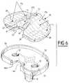
- Fig. 6is a perspective highlighting the structure of the tibial element of the prosthesis.
- Fig. 7is a sectional elevation, similar to FIG. 1 , illustrating the total prosthesis in a particular position of flexion.
- Fig. 1shows the complete prosthesis of the invention consists of a femoral component 1 and a tibial member 2, intended to be adapted, respectively, after bone resection on the epiphysis low 3 femoral and tibial epiphysis high 4.
- the femoral element 1is preferably made of metal and, for example, a chromium-cobalt alloy, well known in the technical field considered.
- the femoral element 1considered according to a lateral view which would be parallel to the sagittal plane of the femur assembly 3 -tibia 4 and, for example, materialized by the line P-P ' in fig. 2 , present, as illustrated in FIG. 1 , a substantially "U" shape comprising a branch 5 , called front or anterior, a branch 6 , called rear or rear of shorter length, and a connecting core 7 .
- the internal surfacedelimited by the femoral element, defines, in a way, a polygonal housing intended to fit the epiphysis 3 subjected, beforehand, to a complementary articular resection.
- the adaptation and connection of the femoral element on the epiphysis 3is ensured, in particular, by means of pins 8 penetrating blind holes in the epiphysis 3 , with or without the presence of bonding cement.
- the internal faces of the branches 5, 6 and of the core 7may have an appropriate surface condition showing a peening, roughness, accidents, spikes, etc., such as the surface accidents bearing the reference 9 in figs. 2 and 5 .
- the femoral element 1is shaped to present, by its outer surface and in relation to the branch 5 , a patellar surface defined by two lateral surfaces 10 and 11 joined by a substantially vertical groove 12 , delimiting a femoral trochlea able to cooperate with the natural protuberance or with an artificial button with the same function presented or carried by the patella, not shown.
- the two lateral surfaces 10 and 11affect, transversely to the sagittal plane, evolving convexities and present, between them, a divergent character from the upper end of the branch 5 , according to orientations O 10 and O 11 materialized in phantom , in particular in fig. 3 .
- the femoral element 1forms, on the external surface and in its part corresponding to the core 7 and to the branch 6 , two condyles 13 and 14 , respectively called internal and external, which follow the divergent lateral surfaces 10 and 11 , for then extend substantially parallel, at least from the middle of the core 7 and along the branch 6 .
- Condyles 13 and 14are defined by an increasing evolving radius of curvature from back to front and materialized in the drawings, for reasons of convenience only, by the vector R of FIG. 1 , centered on center C.
- the condyles 13 and 14are defined, transversely to the sagittal plane, by radii of curvature r which are also variable and different from one condyle to another, the external condyle being transversely more rounded than the internal condyle, such that this appears in the drawings.
- the condyles 13 and 14define between them an intercondylar fossa which is occupied by an intercondylar veil 16 interrupted substantially in the part of the connecting core 7 to delimit a window 17 intended to reduce bone resection.
- the intercondylar veil 16forms, from the rear edge of the window 17 and substantially along the length of the rear or posterior branch 6 , an eminence 18 projecting into the intercondylar fossa 15 and developing towards the rear while being substantially centered on the sagittal P-P plane.
- the eminence 18comprises a front head 19 which is extended, towards the rear, by an elongated body 20 substantially in the form of a semi-toric segment whose radius r 1 of the cross section is, for example, of the order of sixth of the transverse extent of the intercondylar fossa 15 .
- the head 19therefore has a shape which can be deduced as substantially semi-spherical.
- the substantially semi-toric body 20is defined by a radius of curvature R 1 , less than the radius R , centered on a center C 1 which is such that, preferably, the outer periphery of the body 20 extends outside of the envelope materialized by the condyles 13 and 14 .
- the tibial element 2comprises a plate 30 , the lower face of which is provided with at least one tail 31 possibly reinforced by gussets 32 .
- the tail 31is intended to be implanted in the epiphysis 4 , with or without the presence of a bonding cement, as is usually done in implantation of prostheses of the tail type.
- the fixing of the plate 30can also involve the presence of screws mounted through holes 33 .
- the tibial plateau 30is provided with a peripheral edge 34 intended to allow the mounting and immobilization of a shoe 35 illustrated, more precisely, in FIG. 6 .
- the pad 35is preferably made of a suitable plastic material, such as polyethylene, while the plate 30 is made of a metal alloy, similar or identical to that constituting the femoral element 1 .
- the pad 35is preferably but not exclusively, mounted in the tray 30 by interlocking, latching and, for this purpose, comprises, preferably at its rear edge, a rib 36 intended to be snapped into a groove 36 presented by the rear part of the rim 34 .
- the shoe 35is shaped to offer, on its top, a thorn 37 of anteroposterior orientation, on either side of which are formed two glenoid cavities 38 and 39 , respectively called internal and external.
- Each glenoid cavityintended to cooperate as a support seat with the corresponding condyle, is defined by a radius of curvature R 2 parallel to the sagittal plane much greater than the radius of curvature R and by a transverse radius of curvature r 2 which is also larger than the radius r of condyles 13 and 14 .
- the thorn 37develops from the front face of the shoe 35 in the direction of the rear part and is connected to a cavity 40 which is hollowed out from the top of the thorn 37 .
- the cavity 40is defined, in the sagittal plane, by a radius of curvature R 3 which is greater than the radius R 1 and by a transverse radius of curvature r 3 which is greater than that of the semi-toric cross section of the body 20 .
- the cavity 40thus has a form of low hemispherical concavity which provides an open housing for cooperation with the head 19 .
- the cavity 40opens towards the rear and is connected to a groove 41 with divergent sides 42 which end at the rear transverse edge of the shoe 37 .
- the groove 41has, at its bottom and from the rear transverse edge of the shoe 35 , a notch 43 corresponding to a cutout 44 formed in the plate 30 .
- Fig. 1shows that, in a position of substantially alignment between the tibia and the femur, the femoral and tibial elements of the prosthesis, implanted as it is said on the epiphyses 3 and 4 , cooperate with each other via the condyles 13 and 14 and glenoid cavities 38 and 39 .
- the eminence 37is engaged in the intercondylar space, substantially at the birth of the condyles 13 and 14 , in consideration of their connection to the convex lateral surfaces 10 and 11 .
- Such cooperationensures guidance in the anteroposterior plane, without prohibiting a relative rotation of the tibia relative to the femur, due to the conformation of the spine 37 aligned substantially with the anteroposterior plane and connected, from a rounded apex which it has by gentle slopes 37 a and 37 b , with glenoid cavities 38 and 39 .
- the eminence 18is located at the rear of the joint in the raised position relative to the tibial plateau and does not cooperate in any way with the cavity 40 or the groove 41 .
- a flexion of the tibia, in the direction of the arrow f 1does not modify the cooperation ratio of the surfaces up to an angular amplitude such that, according to FIG. 7 , the head 19 is brought to cooperate with the cavity 40 .
- a relative abutmentis then established ensuring post-stabilization between the elements of the prosthesis, so as to prohibit an anterior relative sliding of the femur producing, as is known, a drawer effect in the absence of the cruciate ligaments.
- the body 20is gradually engaged inside the groove 41 to cooperate, by its external generatrix, with the bottom of the cavity 40 , while being kept at a distance from the diverging sides 42 which allow thus, also, a relative rotation of the tibia with respect to the femur.
- the semi-ring body 20is brought substantially into partial engagement within the notch 43.
- the relative rotation of the tibia relative to the femuris also allowed by the conformation of the glenoid cavities 38 and 39 relative to the corresponding condyles 13 and 14 , as well as by the diverging and asymmetrical shape of the latter.
- the prosthesis according to the inventionis able to fulfill the same functions, while allowing a relative rotation of the tibia relative to the femur, to favor internal or external, anatomical and physiological rotation, avoiding subjecting the femoral element and the tibial element to alternating stresses likely to cause an anchoring and fixation disorder.
- the relative rotation authorized by the prosthesis according to the inventionis, moreover, of a nature to maintain a more natural functioning of the remaining ligaments and, in particular, of the internal and external lateral ligaments.
Landscapes
- Health & Medical Sciences (AREA)
- Orthopedic Medicine & Surgery (AREA)
- Physical Education & Sports Medicine (AREA)
- Cardiology (AREA)
- Oral & Maxillofacial Surgery (AREA)
- Transplantation (AREA)
- Engineering & Computer Science (AREA)
- Biomedical Technology (AREA)
- Heart & Thoracic Surgery (AREA)
- Vascular Medicine (AREA)
- Life Sciences & Earth Sciences (AREA)
- Animal Behavior & Ethology (AREA)
- General Health & Medical Sciences (AREA)
- Public Health (AREA)
- Veterinary Medicine (AREA)
- Prostheses (AREA)
Description
Translated fromFrenchLa présente invention est relative aux prothèses du genou et elle vise, plus particulièrement, le domaine des prothèses totales.The present invention relates to knee prostheses and it relates, more particularly, to the field of total prostheses.
Par prothèse totale, il convient de retenir les systèmes articulaires artificiels visant à remplacer l'articulation naturelle constituée par la conformation épiphysaire basse du fémur, par la conformation épiphysaire complémentaire haute du tibia et par l'élément fémoro-patellaire.By total prosthesis, it is advisable to retain the artificial articular systems aiming at replacing the natural articulation constituted by the low epiphyseal conformation of the femur, by the complementary high epiphyseal conformation of the tibia and by the femoro-patellar element.
Il peut être considéré que, dans le domaine technique ci-dessus, les propositions connues de la technique antérieure peuvent se regrouper en deux grandes familles qui, de façon arbitraire, peuvent être dénommées, respectivement, celle des prothèses liées et celle des prothèses libres.It can be considered that, in the above technical field, the known proposals of the prior art can be grouped into two large families which, arbitrarily, can be called, respectively, that of linked prostheses and that of free prostheses.
Par prothèses liées, il convient de retenir celles faisant intervenir deux pièces complémentaires qui sont réunies par un système articulaire matériel, tel qu'au moins un axe, constituant le système de pivotement artificiel, matérialisant l'articulation du genou, selon une direction perpendiculaire au plan sagittal ou antéro-postérieur.By linked prostheses, those involving two complementary parts should be retained which are joined by a material articular system, such as at least one axis, constituting the artificial pivot system, materializing the knee joint, in a direction perpendicular to the sagittal or anteroposterior plane.
La seconde famille, dite libre, est celle comprenant les prothèses constituées à base de deux éléments, respectivement adaptables sur les épiphyses basse du fémur et haute du tibia, pour coopérer, par glissement relatif, en étant maintenus en contact de surface par l'intermédiaire, notamment, des ligaments latéraux interne et externe naturels, sans présence de liens d'articulation entre elles.The second family, known as free, is that comprising prostheses made up of two elements, respectively adaptable on the lower epiphyses of the femur and upper tibia, to cooperate, by relative sliding, while being maintained in surface contact through , in particular, natural internal and external lateral ligaments, without the presence of articulation links between them.
L'invention concerne, uniquement, le domaine des prothèses dites libres.The invention relates only to the field of so-called free prostheses.
Dans le domaine technique que vise l'objet de l'invention, on a proposé, depuis déjà quelques temps, de constituer des prothèses comprenant un élément fémoral adaptable après résection osseuse sur l'extrémité épiphysaire basse du fémur et présentant une partie antérieure délimitant une trochlée fémorale à partir de laquelle s'étendent deux condyles séparés présentant une courbure variable en direction de la face arrière.In the technical field which the object of the invention aims, it has been proposed, for some time now, to constitute prostheses comprising an adaptable femoral element after bone resection on the lower epiphyseal end of the femur and having an anterior part delimiting a femoral trochlea from which extend two separate condyles having a variable curvature in the direction of the rear face.
Une prothèse libre comprend, par ailleurs, pour coopérer avec l'élément fémoral, un élément tibial adaptable après résection sur l'extrémité épiphysaire haute du tibia. Un tel élément tibial offre, en surface supérieure, un patin présentant deux cavités glénoïdes de coopération pour les condyles et une sorte d'arête centrale parallèle au plan sagittal, destinée à être insérée dans l'espace intercondylien de l'élément fémoral.A free prosthesis also comprises, in order to cooperate with the femoral element, an adaptable tibial element after resection on the upper epiphyseal end of the tibia. Such a tibial element offers, on the upper surface, a pad presenting two glenoid cavities of cooperation for the condyles and a sort of central edge parallel to the sagittal plane, intended to be inserted in the intercondylar space of the femoral element.
Une prothèse du genre ci-dessus laisse subsister, entre les condyles séparés, un espace libre permettant le passage des ligaments croisés qui sont responsables, pour l'essentiel, de la tenue du tibia par rapport au fémur dans le plan antéro-postérieur, dans un état de flexion notamment.A prosthesis of the above kind allows a free space to remain between the separated condyles allowing the passage of the cruciate ligaments which are responsible, essentially, for the holding of the tibia relative to the femur in the anteroposterior plane, in a state of flexion in particular.
Dans certains cas particuliers, l'implantation d'une prothèse totale du genou implique de supprimer les ligaments croisés, en raison de leur déficience, de leur désinsertion ou de leur rupture.In certain particular cases, the implantation of a total knee prosthesis implies to remove the cruciate ligaments, due to their deficiency, their disinsertion or their rupture.
Une prothèse totale du type ci-dessus présente alors, lorsqu'elle est implantée dans un tel cas, un inconvénient fonctionnel fondamental dans les mouvements faisant intervenir une flexion, par exemple dans le cas de montée ou de descente d'un escalier ou, encore, dans le cas de passage d'une position assise à une position debout du sujet.A total prosthesis of the above type then has, when implanted in such a case, a fundamental functional drawback in the movements involving bending, for example in the case of climbing or descending a staircase or, even , in the case of changing from a sitting position to a standing position of the subject.
En effet, en l'absence des ligaments croisés, une prothèse du type ci-dessus n'est pas de nature à s'opposer aux mouvements de tiroir du tibia par rapport au fémur, correspondant à un glissement, généralement vers l'arrière, des cavités glénoïdes du tibia par rapport aux condyles. Un tel mouvement de tiroir est traumatisant pour les ligaments latéraux, induit des usures ponctuelles du patin tibial et introduit un facteur de déséquilibre pour le sujet.Indeed, in the absence of the cruciate ligaments, a prosthesis of the above type is not likely to oppose the drawer movements of the tibia relative to the femur, corresponding to a sliding, generally towards the rear, glenoid cavities of the tibia relative to the condyles. Such a drawer movement is traumatic for the lateral ligaments, induces punctual wear of the tibial pad and introduces an imbalance factor for the subject.
Afin de remédier à l'inconvénient ci-dessus, la technique antérieure a vu naître des prothèses totales libres, dites de postéro-stabilisation, en ce sens qu'elles sont conçues pour réintroduire, en l'absence des ligaments croisés, un blocage postérieur s'opposant à l'effet de tiroir.In order to remedy the above drawback, the prior art has seen the emergence of free total prostheses, called post-stabilization, in the sense that they are designed to reintroduce, in the absence of the cruciate ligaments, a blockage posterior opposing the drawer effect.
De telles prothèses, qui peuvent être illustrées par les enseignements des brevets français2 473 876 (81-01 056) et2 615 386 (87-07 353), mettent à profit l'espace intercondylien de l'élément fémoral et comportent, à partir du plateau tibial, une saillie médiane destinée à s'engager dans l'espace intercondylien pour constituer, par sa face arrière, une surface d'appui, généralement à caractère concave.Such prostheses, which can be illustrated by the teachings of the
L'élément fémoral comporte, dans la partie arrière de l'espace intercondylien, une butée de forme générale convexe qui se trouve suffisamment éloignée en position debout pour ne pas coopérer avec la saillie du plateau tibial contre laquelle cette butée est amenée en appui pour une flexion de l'ordre de 60o environ.The femoral element comprises, in the rear part of the intercondylar space, a generally convex abutment which is sufficiently distant in the upright position not to cooperate with the projection of the tibial plateau against which this abutment is brought to bear for a bending of around 60o approximately.
Dans cette position, la butée coopère avec la surface d'appui pour centrer relativement les deux éléments de la prothèse en cours de flexion et s'opposer au glissement relatif responsable de l'effet de tiroir. De telles prothèses sont dénommées à fonction de stabilisation postérieure, en ce sens que les éléments constitutifs trouvent mutuellement un appui relatif arrière lors du déplacement relatif entre le tibia et le fémur.In this position, the stop cooperates with the bearing surface to center relatively the two elements of the prosthesis being bent and to oppose the relative sliding responsible for the drawer effect. Such prostheses are called posterior stabilization function, in the sense that the constituent elements mutually find relative rear support during the relative displacement between the tibia and the femur.
Si la fonction de stabilisation postérieure en flexion est, de la sorte, assumée, il est important de noter que les structures préconisées aboutissent à réaliser des prothèses à caractère guidé, sensiblement parallèlement au plan sagittal, en raison de la pénétration de la saillie du plateau tibial dans l'espace intercondylien de l'élément fémoral.If the function of posterior stabilization in flexion is, in this way, assumed, it is important to note that the recommended structures result in producing prostheses of a guided nature, substantially parallel to the sagittal plane, due to the penetration of the projection of the plate. tibial in the intercondylar space of the femoral element.
Une telle structure se traduit, alors, par une liaison imposée du tibia par rapport au fémur selon le plan sagittal avec une simple possibilité de pivotement relatif sur un axe fictif qui peut être considéré comme étant généralement perpendiculaire au plan sagittal.Such a structure results, then, in an imposed connection of the tibia with respect to the femur according to the sagittal plane with a simple possibility of relative pivoting on a fictitious axis which can be considered as being generally perpendicular to the sagittal plane.
Une telle limitation de mouvement relatif à un seul degré de liberté n'est, en fait, pas compatible avec la caractéristique anatomique du genou naturel qui autorise une rotation relative du tibia par rapport au fémur, avec possibilité d'orientation du pied en rotation interne ou externe sur des plages angulaires, certes limitées, mais néanmoins nécessaires.Such a limitation of movement relating to a single degree of freedom is, in fact, not compatible with the anatomical characteristic of the natural knee which allows relative rotation of the shin relative to the femur, with the possibility of orienting the foot in internal or external rotation over angular ranges, admittedly limited, but nevertheless necessary.
Des prothèses du type ci-dessus interdisent, au contraire, une telle rotation relative, ce qui se traduit par des contraintes importantes qui sont imposées, soit aux éléments en contact et en glissement de la prothèse totale, soit au moyen d'ancrage des éléments de la prothèse sur les épiphyses en vis-à-vis du fémur et du tibia.Prostheses of the above type, on the contrary, prohibit such relative rotation, which results in significant stresses which are imposed either on the elements in contact and in sliding of the total prosthesis, or by means of anchoring of the elements. of the prosthesis on the epiphyses opposite the femur and the tibia.
De telles contraintes sont responsables de douleurs ou de descellement des éléments prothétiques qui doivent faire l'objet d'interventions de consolidation ou de démantellement ou de remembrement.Such constraints are responsible for pain or loosening of the prosthetic elements which must be the subject of consolidation or dismantling or consolidation operations.
La présente invention vise à remédier aux inconvénients ci-dessus en proposant une nouvelle prothèse totale libre postéro-stabilisée du genou, dont la conception est justement prévue pour autoriser, en position postéro-stabilisée de flexion de l'articulation, une possibilité de rotation relative du tibia par rapport au genou, sans supprimer les contacts d'appui fondamentaux devant être maintenus entre les condyles fémoraux et les cavités glénoïdes tibiales.The present invention aims to remedy the above drawbacks by proposing a new free postero-stabilized total knee prosthesis, the design of which is precisely intended to allow, in the postero-stabilized position of flexion of the joint, a possibility of relative rotation of the tibia with respect to the knee, without eliminating the fundamental support contacts to be maintained between the femoral condyles and the tibial glenoid cavities.
Pour atteindre les objectifs ci-dessus, la prothèse selon l'invention est caractérisée en ce que :
- la butée est constituée par une éminence formée en saillie par la partie arrière du voile intercondylien et comprenant une tête antérieure prolongée vers l'arrière par un corps allongé sensiblement en forme de segment semi-torique se développant sensiblement dans le plan sagittal de l'élément,
- et la surface d'appui est définie par une cavité :
- . ménagée à partir du somment d'une épine séparant les cavités glénoïdes depuis le bord antérieur du patin,
- . définie par un rayon de courbure dans le plan sagittal supérieur à celui du segment semi-torique et par un rayon de courbure transversal supérieur à celui de la section transversale dudit segment,
- . s'ouvrant vers l'arrière et se raccordant à un sillon à flancs divergents aboutissant au bord arrière du patin.
- the stop is constituted by an eminence projecting from the rear part of the intercondylar veil and comprising an anterior head extended backwards by an elongated body substantially in the shape of a semi-toric segment developing substantially in the sagittal plane of the element ,
- and the bearing surface is defined by a cavity:
- . formed from the top of a thorn separating the glenoid cavities from the anterior edge of the skate,
- . defined by a radius of curvature in the sagittal plane greater than that of the semi-toric segment and by a transverse radius of curvature than that of the cross section of said segment,
- . opening towards the rear and connecting to a groove with divergent sides leading to the rear edge of the skate.
Diverses autres caractéristiques ressortent de la description faite ci-dessous en référence aux dessins annexés qui montrent, à titre d'exemple non limitatif, une forme de réalisation de l'objet de l'invention.Various other characteristics will emerge from the description given below with reference to the appended drawings which show, by way of nonlimiting example, an embodiment of the subject of the invention.
Lafig. 1 est une coupe-élévation prise selon le plan sagittal de la prothèse selon l'invention considérée dans un état d'implantation réel entre le fémur et le tibia d'un sujet.Fig. 1 is a sectional elevation taken along the sagittal plane of the prosthesis according to the invention considered in a real state of implantation between the femur and the tibia of a subject.
Lesfig. 2 et3 sont des vues transversales prises, respectivement, selon les lignesII-II etIII-III de lafig. 1.Figs. 2 and3 are transverse views taken, respectively, along the linesII-II andIII-III ofFIG. 1 .
Lesfig. 4 et5 sont des perspectives de l'élément de prothèse fémorale permettant de mieux apprécier la structure de cet élément.Figs. 4 and5 are perspectives of the femoral prosthesis element allowing a better appreciation of the structure of this element.
Lafig. 6 est une perspective mettant en évidence la structure de l'élément tibial de la prothèse.Fig. 6 is a perspective highlighting the structure of the tibial element of the prosthesis.
Lafig. 7 est une coupe-élévation, analogue à lafig. 1, illustrant la prothèse totale dans une position particulière de flexion.Fig. 7 is a sectional elevation, similar toFIG. 1 , illustrating the total prosthesis in a particular position of flexion.
Lafig. 1 montre la prothèse totale selon l'invention constituée par un élément fémoral1 et par un élément tibial2, destinés à être adaptés, respectivement, après résection osseuse, sur l'épiphyse basse3 fémorale et l'épiphyse haute4 tibiale.Fig. 1 shows the complete prosthesis of the invention consists of a
L'élément fémoral1, plus particulièrement illustré par lesfig. 2 à 5, est réalisé en métal de préférence et, par exemple, en un alliage chrome-cobalt, bien connu dans le domaine technique considéré.The
L'élément fémoral1, considéré selon une vue latérale qui serait parallèle au plan sagittal de l'ensemble fémur3-tibia4 et, par exemple, matérialisé par la ligneP-P' à lafig. 2, présente, comme cela est illustré par lafig. 1, une forme sensiblement en"U" comprenant une branche5, dite avant ou antérieure, une branche6, dite arrière ou postérieure de plus faible longueur, et une âme7 de liaison.The
La surface interne, délimitée par l'élément fémoral, définit, en quelque sorte, un logement polygonal destiné à emboîter l'épiphyse3 soumise, préalablement, à une résection articulaire complémentaire. L'adaptation et la liaison de l'élément fémoral sur l'épiphyse3 est assurée, notamment, par l'intermédiaire de pions8 pénétrant des trous borgnes dans l'épiphyse3, avec ou sans présence de ciment de liaison. Pour favoriser la repousse osseuse et la liaison interfacielle, les faces internes des branches5, 6 et de l'âme7 peuvent présenter un état de surface approprié faisant apparaître un grenaillage, des aspérités, des accidents, des picots, etc, tels que les accidents de surface portant la référence9 auxfig. 2 et5.The internal surface, delimited by the femoral element, defines, in a way, a polygonal housing intended to fit the
L'élément fémoral1 est conformé pour présenter, par sa surface extérieure et en relation avec la branche5, une surface rotulienne définie par deux surfaces latérales10 et11 réuni es par une rainure12 sensiblement verticale, délimitant une trochlée fémorale apte à coopérer avec la protubérance naturelle ou avec un bouton artificiel à même fonction présenté ou porté par la rotule, non représentée. Les deux surfaces latérales10 et11 affectent, transversalement au plan sagittal, des convexités évolutives et présentent, entre elles, un caractère divergent à partir de l'extrémité supérieure de la branche5, selon des orientationsO10 etO11 matérialisées en trait mixte, en particulier à lafig. 3.The
L'élément fémoral1 forme, en surface extérieure et dans sa partie correspondant à l'âme7 et à la branche6, deux condyles13 et14, respectivement dits intérieur et extérieur, qui font suite aux surfaces latérales10 et11 divergentes, pour s'étendre ensuite de façon sensiblement parallèle, au moins à partir du milieu de l'âme7 et le long de la branche6. Les condyles13 et14 sont définis par un rayon de courbure évolutif croissant d'arrière en avant et matérialisé aux dessins, pour des raisons de commodité uniquement, par le vecteurR de lafig. 1, centré sur le centreC.The
Les condyles13 et14 sont définis, transversalement au plan sagittal, par des rayons de courburer qui sont, également, variables et différents d'un condyle à l'autre, le condyle externe étant transversalement plus bombé que le condyle interne, tel que cela apparaît aux dessins.The
Les condyles13 et14 définissent entre eux une fosse intercondylienne qui est occupée par un voile intercondylien16 interrompu sensiblement dans la partie de l'âme de liaison7 pour délimiter une fenêtre17 destinée à réduire la résection osseuse.The
Le voile intercondylien16 forme, à partir du bord postérieur de la fenêtre17 et sensiblement sur la longueur de la branche arrière ou postérieure6, une éminence18 saillant dans la fosse intercondylienne15 et se développant vers l'arrière en étant sensiblement centrée sur le planP-P' sagittal. L'éminence18 comporte une tête antérieure19 qui est prolongée, vers l'arrière, par un corps allongé20 sensiblement en forme de segment semi-torique dont le rayonr1 de la section transversale est, par exemple, de l'ordre du sixième de l'étendue transversale de la fosse intercondylienne15. La tête19 présente donc une forme pouvant être déduite comme sensiblement semi-sphérique. Le corps sensiblement semi-torique20 est défini par un rayon de courbureR1, inférieur au rayonR, centré sur un centreC1 qui est tel que, de préférence, le pourtour extérieur du corps20 s'étende à l'extérieur de l'enveloppe matérialisée par les condyles13 et14.The
Selon l'invention, l'élément tibial2 comprend un plateau30 dont la face inférieure est pourvue d'au moins une queue31 éventuellement renforcée par des goussets32. La queue31 est destinée à être implantée dans l'épiphyse4, avec ou sans présence d'un ciment de liaison, comme cela se pratique habituellement dans les implantations de prothèses du type à queue. La fixation du plateau30 peut aussi faire intervenir la présence de vis montées à travers des trous33.According to the invention, the
Le plateau tibial30 est pourvu d'un bord périphérique34 destiné à permettre le montage et l'immobilisation d'un patin35 illustré, plus précisément, à lafig. 6. Le patin35 est, de préférence, réalisé en une matière plastique appropriée, telle qu'en polyéthylène, alors que le plateau30 est réalisé en un alliage métallique, semblable ou identique à celui constitutif de l'élément fémoral1. Le patin35 est, de préférence mais non exclusivement, monté dans le plateau30 par emboîtement-encliquetage et, à cette fin, comporte, préférentiellement, sur son bord arrière, une nervure36 destinée à être encliquetée dans une rainure36a présentée par la partie postérieure du rebord34.The
Le patin35 est conformé pour offrir, sur son dessus, une épine37 d'orientation antéro-postérieure, de part et d'autre de laquelle sont formées deux cavités glénoïdes38 et39, respectivement dites interne et externe. Chaque cavité glénoïde, destinée à coopérer en tant que siège d'appui avec le condyle correspondant, est définie par un rayon de courbureR2 parallèle au plan sagittal largement supérieur au rayon de courbureR et par un rayon de courbure transversalr2 qui est lui aussi plus grand que le rayonr des condyles13 et14.The
L'épine37 se développe à partir de la face antérieure du patin35 en direction de la partie arrière et se raccorde à une cavité40 qui est ménagée en creux à partir du sommet de l'épine37. La cavité40 est définie, dans le plan sagittal, par un rayon de courbureR3 qui est plus grand que le rayonR1 et par un rayon de courbure transversalr3 qui est supérieur à celui de la section transversale semi-torique du corps20. La cavité40 présente ainsi une forme de concavité peudo-hémisphérique qui fournit un logement ouvert de coopération avec la tête19. La cavité40 s'ouvre vers l'arrière et se raccorde à un sillon41 à flancs42 divergents qui aboutissent au bord transversal arrière du patin37. De préférence, le sillon41 présente, dans son fond et à partir du bord transversal arrière du patin35, une encoche43 correspondant à une découpe44 ménagée dans le plateau30.The
Lafig. 1 montre que, dans une position sensiblement d'alignement entre le tibia et le fémur, les éléments fémoral et tibial de la prothèse, implantés comme il est dit sur les épiphyses3 et4, coopèrent entre eux par l'intermédiaire des condyles13 et14 et des cavités glénoïdes38 et39. Dans cette position, l'éminence37 est engagée dans l'espace intercondylien, sensiblement à la naissance des condyles13 et14, en considération de leur raccordement aux surfaces latérales convexes10 et11. Une telle coopération assure un guidage dans le plan antéro-postérieur, sans interdire une rotation relative du tibia par rapport au fémur, en raison de la conformation de l'épine37 alignée sensiblement avec le plan antéro-postérieur et raccordée, à partir d'un sommet arrondi qu'elle comporte par des pentes douces37a et37b, aux cavités glénoïdes38 et39.Fig. 1 shows that, in a position of substantially alignment between the tibia and the femur, the femoral and tibial elements of the prosthesis, implanted as it is said on the
Dans cet état, l'éminence18 est située à l'arrière de l'articulation en position surélevée par rapport au plateau tibial et ne coopère aucunement avec la cavité40 ou le sillon41.In this state, the
Une flexion du tibia, dans le sens de la flèchef1 ne modifie pas le rapport de coopération des surfaces jusqu'à une amplitude angulaire telle que, selon lafig. 7, la tête19 est amenée à coopérer avec la cavité40. Il s'établit alors une butée relative assurant une postéro- stabilisation entre les éléments de la prothèse, de manière à interdire un glissement relatif antérieur du fémur produisant, tel que cela est connu, un effet de tiroir en l'absence des ligaments croisés.A flexion of the tibia, in the direction of the arrowf1 does not modify the cooperation ratio of the surfaces up to an angular amplitude such that, according toFIG. 7 , the
En raison de la différence entre les rayonsR1 etR2,r etr2 etr1 etr3, une telle position de butée postérostabilisatrice, interdisant un glissement antérieur du fémur, peut s'apprécier ou être assimilée à une sorte d'articulation à rotule qui présente l'avantage d'autoriser néanmoins, une rotation relative du tibia par rapport au fémur et de favoriser ainsi un fonctionnement anatomique proche, sinon identique, à celui autorisé naturellement par la conformation des surfaces coopérantes du genou et la présence des ligaments croisés et latéraux qui sont responsables du maintien de cette coopération de surface.Because of the difference between the radiiR1 andR2 ,r andr2 andr1 andr3 , such a posterior stabilizing abutment position, preventing anterior sliding of the femur, can be appreciated or be assimilated to a kind of '' ball joint which has the advantage of allowing nevertheless, a relative rotation of the tibia with respect to the femur and thus favoring an anatomical functioning close, if not identical, to that authorized naturally by the conformation of the cooperating surfaces of the knee and the presence cruciate and lateral ligaments which are responsible for maintaining this surface cooperation.
Si la flexion s'accroît, le corps20 est progressivement engagé à l'intérieur du sillon41 pour coopérer, par sa génératrice extérieure, avec le fond de la cavité40, tout en étant maintenu à distance des flancs divergents42 qui, autorisent ainsi, également, une rotation relative du tibia par rapport au fémur.If the flexion increases, the
Lorsqu'une flexion maximale, par exemple de l'ordre de 110o, est atteinte, le corps semi-torique20 est amené sensiblement en engagement partiel à l'intérieur de l'encoche43.Where a maximum flexion, e.g. of the order of 110° is reached, the
La rotation relative du tibia par rapport au fémur est également permise par la conformation des cavités glénoïdes38 et39 relativement aux condyles13 et14 correspondants, ainsi que par la forme divergente et asymétrique de ces derniers.The relative rotation of the tibia relative to the femur is also allowed by the conformation of the
Ainsi, contrairement aux prothèses connues, du type à postéro-stabilisation en l'absence de ligaments croisés, la prothèse selon l'invention est à même de remplir les mêmes fonctions, tout en autorisant une rotation relative du tibia par rapport au fémur, pour favoriser une rotation interne ou externe, anatomique et physiologique, évitant de soumettre l'élément fémoral et l'élément tibial à des contraintes alternées susceptibles de provoquer un désordre d'ancrage et de fixation.Thus, unlike known prostheses, of the post-stabilization type in the absence of cruciate ligaments, the prosthesis according to the invention is able to fulfill the same functions, while allowing a relative rotation of the tibia relative to the femur, to favor internal or external, anatomical and physiological rotation, avoiding subjecting the femoral element and the tibial element to alternating stresses likely to cause an anchoring and fixation disorder.
La rotation relative autorisée par la prothèse conforme à l'invention est, en outre, de nature à entretenir un fonctionnement plus naturel des ligaments subsistant et, notamment, des ligaments latéraux internes et externes.The relative rotation authorized by the prosthesis according to the invention is, moreover, of a nature to maintain a more natural functioning of the remaining ligaments and, in particular, of the internal and external lateral ligaments.
Claims (8)
- A postero-stabilized total prosthesis for the knee, comprising:• a femur element (1) forming:- two anterior lateral surfaces (10, 11) defining between them a femur trochlea (12);- two condyles (13, 14) following on from the lateral surfaces and extending backwards to define an intercondyle gap (15) extending the trochlea; and- a postero-stabilization abutment, oriented towards the front and occupying a portion of the intercondyle gap; and• a tibial element (2) comprising a fitting-and-supporting tray (30) and a pad (35) whose top surface offers, for co-operation with the femur element, two glenoid cavities (38 and 39) and a middle projection (37) defining, towards the back, a bearing surface for the abutment;• the abutment being constituted by a projection (18) projecting from the back portion of an intercondyle web (16) and including an anterior head (19) extended towards the back by an elongate body (20) substantially in the form of a semi-toroidal segment that is developed substantially in the sagittal plane (P-P') of the element; and• the bearing surface being defined by a cavity (40):- formed from the top of a spine (37) separating the glenoid cavities from the anterior edge of the pad;- defined by a radius of curvature (R3) in the sagittal plane greater than the radius of curvature of the semi-toroidal segment; and- opening towards the back and connecting to a ferrule (41) having diverging flanks (42) terminating at the rear edge of the pad, the prosthesis being characterized by a transverse radius of curvature (r3) of said cavity (40) that is greater than the radius of curvature of the cross-section of said segment.
- A prosthesis according to claim 1, characterized in that the glenoid cavities provide hollow bearing surfaces defined parallel to the sagittal plane by curvature (R2) of radius greater than the radius (R) of the condyles, and perpendicularly to said plane, by curvature (r2) of radius greater than the transverse radius (r) of the convex shape of the condyles.
- A prosthesis according to claim 1 or 2, characterized in that the glenoid cavities are substantially parallel to each other, while the condyles converge towards the lateral surfaces.
- A prosthesis according to claim 1, characterized in that the intercondyle gap (15) is open in its portion between the head of the abutment and the bottom of the trochlea.
- A prosthesis according to claim 1, characterized in that the projection (18) is organized so that the head (19) co-operates in abutment against the cavity when the prosthesis in the flexed state.
- A prosthesis according to claim 1 or 5, characterized in that the cavity (18) reaches a ferrule (41) having diverging sides (42) opening out to the posterior edge of the pad (35).
- A prosthesis according to claim 1 or 5, characterized in that the projection (18) extends at least in part outside the envelope occupied by the condyles.
- A prosthesis according to claim 1, characterized in that the pad (35) is mounted in the tray by engagement and snap-fastening of a rib (36) in an internal groove (36a) of a peripheral rim (34) of the tray.
Priority Applications (3)
| Application Number | Priority Date | Filing Date | Title |
|---|---|---|---|
| DE1992620779DE69220779T2 (en) | 1992-04-30 | 1992-04-30 | "Backward stabilized total knee prosthesis" |
| ES92420144TES2108100T3 (en) | 1992-04-30 | 1992-04-30 | TOTAL POSTERO-STABILIZED KNEE PROSTHESIS. |
| EP19920420144EP0567705B1 (en) | 1992-04-30 | 1992-04-30 | Posteriorly stabilized total knee prosthesis |
Applications Claiming Priority (1)
| Application Number | Priority Date | Filing Date | Title |
|---|---|---|---|
| EP19920420144EP0567705B1 (en) | 1992-04-30 | 1992-04-30 | Posteriorly stabilized total knee prosthesis |
Publications (2)
| Publication Number | Publication Date |
|---|---|
| EP0567705A1 EP0567705A1 (en) | 1993-11-03 |
| EP0567705B1true EP0567705B1 (en) | 1997-07-09 |
Family
ID=8211743
Family Applications (1)
| Application Number | Title | Priority Date | Filing Date |
|---|---|---|---|
| EP19920420144Expired - LifetimeEP0567705B1 (en) | 1992-04-30 | 1992-04-30 | Posteriorly stabilized total knee prosthesis |
Country Status (3)
| Country | Link |
|---|---|
| EP (1) | EP0567705B1 (en) |
| DE (1) | DE69220779T2 (en) |
| ES (1) | ES2108100T3 (en) |
Cited By (11)
| Publication number | Priority date | Publication date | Assignee | Title |
|---|---|---|---|---|
| DE19755776A1 (en)* | 1997-12-16 | 1999-07-01 | Chiropro Gmbh | Prosthesis part e.g. knee or hip joint with parallel grooves |
| US7115131B2 (en) | 2001-06-14 | 2006-10-03 | Alexandria Research Technologies, Llc | Apparatus and method for sculpting the surface of a joint |
| US8551179B2 (en) | 2011-06-16 | 2013-10-08 | Zimmer, Inc. | Femoral prosthesis system having provisional component with visual indicators |
| US8932365B2 (en) | 2011-06-16 | 2015-01-13 | Zimmer, Inc. | Femoral component for a knee prosthesis with improved articular characteristics |
| US9060868B2 (en) | 2011-06-16 | 2015-06-23 | Zimmer, Inc. | Femoral component for a knee prosthesis with bone compacting ridge |
| US9173744B2 (en) | 2010-09-10 | 2015-11-03 | Zimmer Gmbh | Femoral prosthesis with medialized patellar groove |
| US9301845B2 (en) | 2005-06-15 | 2016-04-05 | P Tech, Llc | Implant for knee replacement |
| US9308095B2 (en) | 2011-06-16 | 2016-04-12 | Zimmer, Inc. | Femoral component for a knee prosthesis with improved articular characteristics |
| US9592127B2 (en) | 2005-12-15 | 2017-03-14 | Zimmer, Inc. | Distal femoral knee prostheses |
| US10130375B2 (en) | 2014-07-31 | 2018-11-20 | Zimmer, Inc. | Instruments and methods in performing kinematically-aligned total knee arthroplasty |
| US10136997B2 (en) | 2015-09-29 | 2018-11-27 | Zimmer, Inc. | Tibial prosthesis for tibia with varus resection |
Families Citing this family (11)
| Publication number | Priority date | Publication date | Assignee | Title |
|---|---|---|---|---|
| FR2718952B1 (en)* | 1994-04-25 | 1996-07-19 | Landanger Landos | Total knee prosthesis with central post-stabilization condyle. |
| FR2725618B1 (en)* | 1994-10-17 | 1997-04-04 | France Bloc | FEMALE KNEE JOINT PROSTHESIS |
| DE19708375A1 (en)* | 1997-01-17 | 1998-07-23 | Ceramtec Ag | Fixation of a tibia part on a tibial plateau of a knee joint endoprosthesis |
| JP2002527193A (en)* | 1998-10-16 | 2002-08-27 | ピーター、 スタンリー ウォーカー、 | Jelly bean type knee joint improvement |
| FR2835738B1 (en)* | 2002-02-14 | 2004-10-01 | Jacques Afriat | TOTAL KNEE PROSTHESIS |
| DE10220591B4 (en)* | 2002-05-08 | 2004-03-18 | Mathys Medizinaltechnik Ag | Joint prosthesis with an intermediate element with different radii of curvature |
| US8535383B2 (en) | 2004-01-12 | 2013-09-17 | DePuy Synthes Products, LLC | Systems and methods for compartmental replacement in a knee |
| US8002840B2 (en) | 2004-01-12 | 2011-08-23 | Depuy Products, Inc. | Systems and methods for compartmental replacement in a knee |
| US7544209B2 (en) | 2004-01-12 | 2009-06-09 | Lotke Paul A | Patello-femoral prosthesis |
| JP4510030B2 (en) | 2004-01-12 | 2010-07-21 | デピュイ・プロダクツ・インコーポレイテッド | System and method for splitting and replacing a knee |
| EP3634319B1 (en) | 2017-06-04 | 2021-04-14 | Stefan Eggli | Modular knee prosthesis |
Family Cites Families (2)
| Publication number | Priority date | Publication date | Assignee | Title |
|---|---|---|---|---|
| FR2615386A1 (en)* | 1987-05-21 | 1988-11-25 | Tornier Sa | TOTAL KNEE PROSTHESIS |
| US4892547A (en)* | 1988-02-03 | 1990-01-09 | Biomet, Inc. | Partially stabilized knee prosthesis |
- 1992
- 1992-04-30EPEP19920420144patent/EP0567705B1/ennot_activeExpired - Lifetime
- 1992-04-30ESES92420144Tpatent/ES2108100T3/ennot_activeExpired - Lifetime
- 1992-04-30DEDE1992620779patent/DE69220779T2/ennot_activeExpired - Fee Related
Cited By (28)
| Publication number | Priority date | Publication date | Assignee | Title |
|---|---|---|---|---|
| DE19755776C2 (en)* | 1997-12-16 | 2000-03-09 | Chiropro Gmbh | Prosthesis part, in particular a knee joint prosthesis or a hip joint prosthesis |
| DE19755776A1 (en)* | 1997-12-16 | 1999-07-01 | Chiropro Gmbh | Prosthesis part e.g. knee or hip joint with parallel grooves |
| US7115131B2 (en) | 2001-06-14 | 2006-10-03 | Alexandria Research Technologies, Llc | Apparatus and method for sculpting the surface of a joint |
| US7520901B2 (en) | 2001-06-14 | 2009-04-21 | Alexandria Research Technologies, Inc. | Bicompartmental implants and method of use |
| US7896922B2 (en) | 2001-06-14 | 2011-03-01 | Alexandria Research Technologies, Llc | Implants for partial knee arthroplasty |
| US9301845B2 (en) | 2005-06-15 | 2016-04-05 | P Tech, Llc | Implant for knee replacement |
| US9592127B2 (en) | 2005-12-15 | 2017-03-14 | Zimmer, Inc. | Distal femoral knee prostheses |
| US10433966B2 (en) | 2005-12-15 | 2019-10-08 | Zimmer, Inc. | Distal femoral knee prostheses |
| US10322004B2 (en) | 2010-09-10 | 2019-06-18 | Zimmer Gmbh | Femoral prosthesis with lateralized patellar groove |
| US9173744B2 (en) | 2010-09-10 | 2015-11-03 | Zimmer Gmbh | Femoral prosthesis with medialized patellar groove |
| US9867708B2 (en) | 2010-09-10 | 2018-01-16 | Zimmer Gmbh | Femoral prosthesis with lateralized patellar groove |
| US9993345B2 (en) | 2011-06-16 | 2018-06-12 | Zimmer, Inc. | Femoral prosthesis system |
| US8551179B2 (en) | 2011-06-16 | 2013-10-08 | Zimmer, Inc. | Femoral prosthesis system having provisional component with visual indicators |
| US9308095B2 (en) | 2011-06-16 | 2016-04-12 | Zimmer, Inc. | Femoral component for a knee prosthesis with improved articular characteristics |
| US9060868B2 (en) | 2011-06-16 | 2015-06-23 | Zimmer, Inc. | Femoral component for a knee prosthesis with bone compacting ridge |
| US10045850B2 (en) | 2011-06-16 | 2018-08-14 | Zimmer, Inc. | Femoral component for a knee prosthesis with improved articular characteristics |
| US10070966B2 (en) | 2011-06-16 | 2018-09-11 | Zimmer, Inc. | Femoral component for a knee prosthesis with bone compacting ridge |
| US12213889B2 (en) | 2011-06-16 | 2025-02-04 | Zimmer, Inc. | Femoral component for a knee prosthesis with improved articular characteristics |
| US12048630B2 (en) | 2011-06-16 | 2024-07-30 | Zimmer, Inc. | Femoral component for a knee prosthesis with improved articular characteristics |
| US8932365B2 (en) | 2011-06-16 | 2015-01-13 | Zimmer, Inc. | Femoral component for a knee prosthesis with improved articular characteristics |
| US9629723B2 (en) | 2011-06-16 | 2017-04-25 | Zimmer, Inc. | Femoral component for a knee prosthesis with improved articular characteristics |
| US10441429B2 (en) | 2011-06-16 | 2019-10-15 | Zimmer, Inc. | Femoral component for a knee prosthesis with improved articular characteristics |
| US11246710B2 (en) | 2011-06-16 | 2022-02-15 | Zimmer, Inc. | Femoral component for a knee prosthesis with improved articular characteristics |
| US10939923B2 (en) | 2014-07-31 | 2021-03-09 | Zimmer, Inc. | Instruments and methods in performing kinematically-aligned total knee arthroplasty |
| US10130375B2 (en) | 2014-07-31 | 2018-11-20 | Zimmer, Inc. | Instruments and methods in performing kinematically-aligned total knee arthroplasty |
| US10631991B2 (en) | 2015-09-29 | 2020-04-28 | Zimmer, Inc. | Tibial prosthesis for tibia with varus resection |
| US11491018B2 (en) | 2015-09-29 | 2022-11-08 | Zimmer, Inc. | Tibial prosthesis for tibia with varus resection |
| US10136997B2 (en) | 2015-09-29 | 2018-11-27 | Zimmer, Inc. | Tibial prosthesis for tibia with varus resection |
Also Published As
| Publication number | Publication date |
|---|---|
| EP0567705A1 (en) | 1993-11-03 |
| DE69220779T2 (en) | 1997-12-18 |
| ES2108100T3 (en) | 1997-12-16 |
| DE69220779D1 (en) | 1997-08-14 |
Similar Documents
| Publication | Publication Date | Title |
|---|---|---|
| EP0567705B1 (en) | Posteriorly stabilized total knee prosthesis | |
| CA2726034C (en) | Total knee prosthesis | |
| EP1025819B1 (en) | Knee prosthesis with an insert, which is mobile in relation to a post | |
| EP0196258B1 (en) | Cementless femoral component of a hip prosthesis | |
| FR2634373A1 (en) | Total knee prosthesis | |
| EP0913134B1 (en) | Knee prostheseis | |
| EP0864305B1 (en) | Ankle prosthesis | |
| EP1354571B1 (en) | Total knee prothesis | |
| EP0709074B1 (en) | Tibial-prosthetic part for knee prosthesis | |
| FR2719466A1 (en) | Knee prosthesis with movable meniscus. | |
| FR2871678A1 (en) | TOTAL KNEE PROSTHESIS | |
| FR2791553A1 (en) | ANTERO-POSTERO-STABILIZED KNEE PROSTHESIS | |
| FR2800601A1 (en) | ANKLE PROSTHESIS | |
| EP2585001B1 (en) | Orthopedic device to be provided on the knee joint | |
| BE1011626A3 (en) | A total knee prosthesis tibial plateau mobile rotating. | |
| FR2601873A1 (en) | Intracondylar total knee prosthesis | |
| EP1862150A1 (en) | Total knee joint prosthesis | |
| FR2780636A1 (en) | Modular knee prosthesis comprises lower femoral mounting plate and upper tibial plate for total knee prosthesis | |
| FR2682589A1 (en) | Trochlear element for femoral/knee ball prosthesis | |
| FR2852819A1 (en) | Knee prosthesis, has condyles and glenoid cavities with interior parts having radius of curvature more than radius of curvature of their posterior parts to ensure posterior stabilization | |
| WO2009092907A2 (en) | Intervertebral disc prosthesis | |
| FR2805456A1 (en) | Postero-stabilised knee prosthesis has femoral implant and three condyles with pivoted meniscal plate with engaging surfaces | |
| WO1996000538A1 (en) | Prosthetic knee joint, particularly a single-compartment knee prosthesis or a kneecap prosthesis | |
| EP3854355B1 (en) | Implantable component with improved anchoring means for ankle prosthesis and ankle prosthesis comprising such a component | |
| FR2684291A1 (en) | Ankle prosthesis |
Legal Events
| Date | Code | Title | Description |
|---|---|---|---|
| PUAI | Public reference made under article 153(3) epc to a published international application that has entered the european phase | Free format text:ORIGINAL CODE: 0009012 | |
| AK | Designated contracting states | Kind code of ref document:A1 Designated state(s):BE CH DE ES FR GB IT LI LU NL SE | |
| 17P | Request for examination filed | Effective date:19940427 | |
| 17Q | First examination report despatched | Effective date:19951018 | |
| RAP1 | Party data changed (applicant data changed or rights of an application transferred) | Owner name:COLLOMB, JEAN Owner name:MERCK BIOMATERIAL FRANCE S.A. | |
| GRAH | Despatch of communication of intention to grant a patent | Free format text:ORIGINAL CODE: EPIDOS IGRA | |
| GRAH | Despatch of communication of intention to grant a patent | Free format text:ORIGINAL CODE: EPIDOS IGRA | |
| GRAA | (expected) grant | Free format text:ORIGINAL CODE: 0009210 | |
| RAP1 | Party data changed (applicant data changed or rights of an application transferred) | Owner name:COLLOMB, JEAN Owner name:MERCK BIOMATERIAL FRANCE | |
| AK | Designated contracting states | Kind code of ref document:B1 Designated state(s):BE CH DE ES FR GB IT LI LU NL SE | |
| PG25 | Lapsed in a contracting state [announced via postgrant information from national office to epo] | Ref country code:NL Free format text:LAPSE BECAUSE OF FAILURE TO SUBMIT A TRANSLATION OF THE DESCRIPTION OR TO PAY THE FEE WITHIN THE PRESCRIBED TIME-LIMIT Effective date:19970709 | |
| REG | Reference to a national code | Ref country code:CH Ref legal event code:EP | |
| REF | Corresponds to: | Ref document number:69220779 Country of ref document:DE Date of ref document:19970814 | |
| GBT | Gb: translation of ep patent filed (gb section 77(6)(a)/1977) | Effective date:19970822 | |
| ITF | It: translation for a ep patent filed | ||
| PG25 | Lapsed in a contracting state [announced via postgrant information from national office to epo] | Ref country code:SE Effective date:19971009 | |
| REG | Reference to a national code | Ref country code:CH Ref legal event code:NV Representative=s name:BOVARD AG PATENTANWAELTE | |
| NLV1 | Nl: lapsed or annulled due to failure to fulfill the requirements of art. 29p and 29m of the patents act | ||
| REG | Reference to a national code | Ref country code:ES Ref legal event code:FG2A Ref document number:2108100 Country of ref document:ES Kind code of ref document:T3 | |
| PLBE | No opposition filed within time limit | Free format text:ORIGINAL CODE: 0009261 | |
| 26N | No opposition filed | ||
| PGFP | Annual fee paid to national office [announced via postgrant information from national office to epo] | Ref country code:CH Payment date:19990419 Year of fee payment:8 | |
| PGFP | Annual fee paid to national office [announced via postgrant information from national office to epo] | Ref country code:LU Payment date:19990421 Year of fee payment:8 | |
| PGFP | Annual fee paid to national office [announced via postgrant information from national office to epo] | Ref country code:BE Payment date:19990517 Year of fee payment:8 | |
| PG25 | Lapsed in a contracting state [announced via postgrant information from national office to epo] | Ref country code:LU Free format text:LAPSE BECAUSE OF NON-PAYMENT OF DUE FEES Effective date:20000430 Ref country code:LI Free format text:LAPSE BECAUSE OF NON-PAYMENT OF DUE FEES Effective date:20000430 Ref country code:CH Free format text:LAPSE BECAUSE OF NON-PAYMENT OF DUE FEES Effective date:20000430 Ref country code:BE Free format text:LAPSE BECAUSE OF NON-PAYMENT OF DUE FEES Effective date:20000430 | |
| BERE | Be: lapsed | Owner name:COLLOMB JEAN Effective date:20000430 Owner name:MERCK BIOMATERIAL FRANCE Effective date:20000430 | |
| REG | Reference to a national code | Ref country code:CH Ref legal event code:PL | |
| REG | Reference to a national code | Ref country code:GB Ref legal event code:IF02 | |
| PGFP | Annual fee paid to national office [announced via postgrant information from national office to epo] | Ref country code:DE Payment date:20020410 Year of fee payment:11 | |
| PGFP | Annual fee paid to national office [announced via postgrant information from national office to epo] | Ref country code:ES Payment date:20020412 Year of fee payment:11 | |
| PGFP | Annual fee paid to national office [announced via postgrant information from national office to epo] | Ref country code:GB Payment date:20020423 Year of fee payment:11 | |
| PG25 | Lapsed in a contracting state [announced via postgrant information from national office to epo] | Ref country code:GB Free format text:LAPSE BECAUSE OF NON-PAYMENT OF DUE FEES Effective date:20030430 | |
| PG25 | Lapsed in a contracting state [announced via postgrant information from national office to epo] | Ref country code:ES Free format text:LAPSE BECAUSE OF NON-PAYMENT OF DUE FEES Effective date:20030503 | |
| PG25 | Lapsed in a contracting state [announced via postgrant information from national office to epo] | Ref country code:DE Free format text:LAPSE BECAUSE OF NON-PAYMENT OF DUE FEES Effective date:20031101 | |
| GBPC | Gb: european patent ceased through non-payment of renewal fee | ||
| REG | Reference to a national code | Ref country code:ES Ref legal event code:FD2A Effective date:20030503 | |
| PG25 | Lapsed in a contracting state [announced via postgrant information from national office to epo] | Ref country code:IT Free format text:LAPSE BECAUSE OF NON-PAYMENT OF DUE FEES;WARNING: LAPSES OF ITALIAN PATENTS WITH EFFECTIVE DATE BEFORE 2007 MAY HAVE OCCURRED AT ANY TIME BEFORE 2007. THE CORRECT EFFECTIVE DATE MAY BE DIFFERENT FROM THE ONE RECORDED. Effective date:20050430 | |
| PGFP | Annual fee paid to national office [announced via postgrant information from national office to epo] | Ref country code:FR Payment date:20110428 Year of fee payment:20 |