EP0567510B1 - Plastic syringe - Google Patents
Plastic syringeDownload PDFInfo
- Publication number
- EP0567510B1 EP0567510B1EP92902915AEP92902915AEP0567510B1EP 0567510 B1EP0567510 B1EP 0567510B1EP 92902915 AEP92902915 AEP 92902915AEP 92902915 AEP92902915 AEP 92902915AEP 0567510 B1EP0567510 B1EP 0567510B1
- Authority
- EP
- European Patent Office
- Prior art keywords
- closure
- needle fitting
- needle
- fitting
- syringe
- Prior art date
- Legal status (The legal status is an assumption and is not a legal conclusion. Google has not performed a legal analysis and makes no representation as to the accuracy of the status listed.)
- Expired - Lifetime
Links
- 229920003023plasticPolymers0.000titleclaimsabstractdescription16
- 239000004033plasticSubstances0.000titleclaimsabstractdescription15
- 238000002347injectionMethods0.000claimsabstractdescription6
- 239000007924injectionSubstances0.000claimsabstractdescription6
- 239000007788liquidSubstances0.000claimsdescription9
- 230000002093peripheral effectEffects0.000claimsdescription5
- 229940102223injectable solutionDrugs0.000description4
- 239000000463materialSubstances0.000description3
- 230000006378damageEffects0.000description2
- 239000004952PolyamideSubstances0.000description1
- 239000004743PolypropyleneSubstances0.000description1
- 208000027418Wounds and injuryDiseases0.000description1
- 238000007792additionMethods0.000description1
- 230000004075alterationEffects0.000description1
- 239000003708ampulSubstances0.000description1
- 230000004888barrier functionEffects0.000description1
- 230000003203everyday effectEffects0.000description1
- 239000012530fluidSubstances0.000description1
- 230000006872improvementEffects0.000description1
- 208000014674injuryDiseases0.000description1
- 230000002452interceptive effectEffects0.000description1
- 230000004048modificationEffects0.000description1
- 238000012986modificationMethods0.000description1
- 229920002647polyamidePolymers0.000description1
- -1polypropylenePolymers0.000description1
- 229920001155polypropylenePolymers0.000description1
- 229940071643prefilled syringeDrugs0.000description1
- 230000002028prematureEffects0.000description1
- 238000000926separation methodMethods0.000description1
- 239000000243solutionSubstances0.000description1
- 230000001954sterilising effectEffects0.000description1
- 229920001169thermoplasticPolymers0.000description1
- 239000004416thermosoftening plasticSubstances0.000description1
Images


Classifications
- A—HUMAN NECESSITIES
- A61—MEDICAL OR VETERINARY SCIENCE; HYGIENE
- A61M—DEVICES FOR INTRODUCING MEDIA INTO, OR ONTO, THE BODY; DEVICES FOR TRANSDUCING BODY MEDIA OR FOR TAKING MEDIA FROM THE BODY; DEVICES FOR PRODUCING OR ENDING SLEEP OR STUPOR
- A61M5/00—Devices for bringing media into the body in a subcutaneous, intra-vascular or intramuscular way; Accessories therefor, e.g. filling or cleaning devices, arm-rests
- A61M5/178—Syringes
- A61M5/31—Details
- A61M5/3129—Syringe barrels
- A61M5/3134—Syringe barrels characterised by constructional features of the distal end, i.e. end closest to the tip of the needle cannula
- A—HUMAN NECESSITIES
- A61—MEDICAL OR VETERINARY SCIENCE; HYGIENE
- A61M—DEVICES FOR INTRODUCING MEDIA INTO, OR ONTO, THE BODY; DEVICES FOR TRANSDUCING BODY MEDIA OR FOR TAKING MEDIA FROM THE BODY; DEVICES FOR PRODUCING OR ENDING SLEEP OR STUPOR
- A61M5/00—Devices for bringing media into the body in a subcutaneous, intra-vascular or intramuscular way; Accessories therefor, e.g. filling or cleaning devices, arm-rests
- A61M5/178—Syringes
- A61M5/31—Details
- A61M5/32—Needles; Details of needles pertaining to their connection with syringe or hub; Accessories for bringing the needle into, or holding the needle on, the body; Devices for protection of needles
- A61M5/34—Constructions for connecting the needle, e.g. to syringe nozzle or needle hub
- A—HUMAN NECESSITIES
- A61—MEDICAL OR VETERINARY SCIENCE; HYGIENE
- A61M—DEVICES FOR INTRODUCING MEDIA INTO, OR ONTO, THE BODY; DEVICES FOR TRANSDUCING BODY MEDIA OR FOR TAKING MEDIA FROM THE BODY; DEVICES FOR PRODUCING OR ENDING SLEEP OR STUPOR
- A61M5/00—Devices for bringing media into the body in a subcutaneous, intra-vascular or intramuscular way; Accessories therefor, e.g. filling or cleaning devices, arm-rests
- A61M5/178—Syringes
- A61M5/31—Details
- A61M2005/3103—Leak prevention means for distal end of syringes, i.e. syringe end for mounting a needle
- A61M2005/3104—Caps for syringes without needle
- A—HUMAN NECESSITIES
- A61—MEDICAL OR VETERINARY SCIENCE; HYGIENE
- A61M—DEVICES FOR INTRODUCING MEDIA INTO, OR ONTO, THE BODY; DEVICES FOR TRANSDUCING BODY MEDIA OR FOR TAKING MEDIA FROM THE BODY; DEVICES FOR PRODUCING OR ENDING SLEEP OR STUPOR
- A61M5/00—Devices for bringing media into the body in a subcutaneous, intra-vascular or intramuscular way; Accessories therefor, e.g. filling or cleaning devices, arm-rests
- A61M5/178—Syringes
- A61M5/31—Details
- A61M2005/3117—Means preventing contamination of the medicament compartment of a syringe
- A61M2005/3118—Means preventing contamination of the medicament compartment of a syringe via the distal end of a syringe, i.e. syringe end for mounting a needle cannula
- A61M2005/312—Means preventing contamination of the medicament compartment of a syringe via the distal end of a syringe, i.e. syringe end for mounting a needle cannula comprising sealing means, e.g. severable caps, to be removed prior to injection by, e.g. tearing or twisting
- A—HUMAN NECESSITIES
- A61—MEDICAL OR VETERINARY SCIENCE; HYGIENE
- A61M—DEVICES FOR INTRODUCING MEDIA INTO, OR ONTO, THE BODY; DEVICES FOR TRANSDUCING BODY MEDIA OR FOR TAKING MEDIA FROM THE BODY; DEVICES FOR PRODUCING OR ENDING SLEEP OR STUPOR
- A61M5/00—Devices for bringing media into the body in a subcutaneous, intra-vascular or intramuscular way; Accessories therefor, e.g. filling or cleaning devices, arm-rests
- A61M5/178—Syringes
- A61M5/28—Syringe ampoules or carpules, i.e. ampoules or carpules provided with a needle
- A61M5/285—Syringe ampoules or carpules, i.e. ampoules or carpules provided with a needle with sealing means to be broken or opened
Definitions
- This inventionrelates to a disposable syringe intended for single use.
- Single use disposable syringes for medical purposesare well known and are in everyday use. Such syringes are more convenient than re-usable syringes as there is no need for the medical practioner to maintain sterilising facilities for the various components used with re-usable syringes.
- a disposable syringecan be prepackaged in a sterile condition and thus be available for use immediately when required. This makes such syringes particularly useful when administration of any particular injectable is required in emergency situations.
- the disposable syringebe pre-filled so that it is not necessary to transfer the injectable solution from a separate ampoule prior to use.
- a pre-filled disposable plastics syringecomprising an open ended barrel having a needle fitting disposed at one end and being sealed at the other end of the barrel by a movable stopper wherein said needle fitting end of the barrel is sealed by a frangible closure which is integral with the needle fitting, said closure being adapted to co-operate with a hyperdermic needle support shaped to fit onto said needle fitting such that application of a downward force on said hyperdermic needle support onto said needle fitting causes said closure to separate from the needle fitting and move at least some way into the body of the syringe and thereby reveal the contents of the syringe for injection.
- the closureis in the form of a stem having a diameter approximately equal to or smaller than the smallest internal diameter of the needle fitting. It will be apparent to those skilled in the art that the frangible connection of the closure to the needle fitting can be positioned in a number of convenient locations. In one embodiment, this connection is located at the very end of the needle fitting. In the most preferred embodiment of the invention, the point of connection is located a small distance within the needle fitting. This position is preferred because it results in part of the closure member being located within the syringe prior to the application of any separating force. The top end of the needle fitting thereby acts as a guide ensuring that the closure member cleanly enters the body of the syringe upon the application of the separating force.
- the closureis preferably of smaller cross section than the needle fitting opening and connected to the internal wall of the needle fitting by a circumferential web. Once this web tears, the closure is of appropriate size to readily move down inside the body of the syringe.
- the body of the syringecan be seen as comprising two separate internal compartments. The first being immediately inside the needle fitting section of the syringe body ("the needle fitting compartment") and the second being the remaining section sealed by the stopper at the other end of the syringe body ("the main body compartment"). From a user-confidence perspective it is perceived by the applicant that it would be undesirable for the closure once separated from the needle fitting to drop right down into the main body compartment as it would be seen drifting about in the injectable solution. There would of course be no functional or medical difficulty in this regard as the closure could be fully sterilised.
- the internal wall of the needle fittingcomprise a stop member that prevents the movement of the closure through to the main body compartment.
- the stop membercan be of any convenient shape which acts as a barrier to the further travel of the closure but is desirably in the shape of a peripheral shoulder which reduces the internal diameter of the needle fitting to a size smaller than the end of the closure.
- the closureis provided with liquid access means.
- the meansshould allow access of liquid past the closure even if it is pressed up immediately adjacent the hyperdermic needle inlet aperture. It will be appreciated that such means may be provided by use of any of a number of different profiles including, corrugations, spiral channels or some other form of channelling.
- the liquid access meansis provided by a plurality of longitudinally extending channels extending along the full length of the closure. Most preferably, the end of the closure has an internal recess which in conjunction with the longitudinal channels ensures that the hyperdermic needle inlet apperature is not blocked.
- the needle fitting moulded into the end of the syringe bodycan be of any desired form. It is preferably a standard form such as a screw thread fitting or a luer lock fitting.
- the syringe bodyis also preferably moulded with an integral handle in any of the profiles well known in the art.
- An overcapmay also be provided to protect the closure from damage which could cause premature opening of the syringe.
- a plunger rodis connected to the end of the stopper located in the open end of the syringe barrel.
- a hyperdermic needle and supportare then placed in position over the top of the closure and onto the top of the needle fitting.
- the hyperdermic needleitself is also normally provided with an overcap to reduce the risk of injury whilst the needle is being fitted to the syringe.
- the hyperdermic needle supportis then pushed down onto the needle fitting causing the closure to separate from the needle fitting and thereby reveal the contents of the syringe for injection. If a hyperdermic needle overcap is provided, this is then removed and the syringe is ready for use.
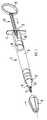
- Syringe 1comprises an open ended barrel 2 which is sealed at open end 3 by stopper 4.
- a handle 5is conveniently provided at the end of barrel 2.
- a needle fitting 6is located at the other end of the barrel 2 and comprises an integral closure 7 which is connected to the inside wall 8 of needle fitting 6 (see Figure 2). Closure 7 and needle fitting 6 are protected by overcap 9 which is shaped to fit over the closure 7 and around the needle fitting 6.
- Needle fitting 6is in the form of a standard luer lock comprising a luer cone 10 and an outer wall 11 comprising a screw thread 12 about its inner peripheral wall.
- Plunger 13is adapted to co-operate with movable stopper 4 to enable the injectable solution contained within barrel 2 to be expressed once closure 7 is separated from needle fitting inside wall 8.
- Plunger 13comprises stopper engaging means 14 and a plunger grip 15.
- FIGS 2 and 3illustrate cross-sectional details of the needle fitting 6 and associated closure 7.
- closure 7is connected to the inside wall 8 of needle fitting 6 by peripheral web 16.
- Closure 7extends below peripheral web 16 and comprises a base 17 provided with a sloping base wall 18.
- Needle fitting 6, as illustrated in figure 2is in the form of a luer lock needle fitting which comprises a luer cone 10 and an outer circumferential wall 11.
- the outer circumferential wall 11includes a screw thread 12 positioned about the inner face of this wall.
- a stopping meansis provided by shoulder 19 positioned approximately midway along the length of inside wall 8 of needle fitting 6.
- FIG 3there is illustrated the needle fitting of figure 2 with a hyperdermic needle 20 and hyperdermic needle support 21 placed generally in position over the top of closure 7 and needle fitting 6.
- Figure 3provides further detail of closure 7.
- Liquid access meansis provided by a plurality of longitudinal channels 22 and recess 23 located at the top of closure 7.
- a top plan view of closure 7is shown in figure 4.
- hyperdermic needle support 21is pushed down onto the luer cone 10 of needle fitting 6. Before the hyperdermic needle 20 and hyperdermic needle support 21 can be pushed firmly into position, it is necessary to rupture connecting web 16 and thus separate closure 7 from inside wall 8 of needle fitting 6.
- Figures 5 and 6illustrate this embodiment of the invention following the separation of the closure from inner wall 8 with hyperdermic needle support 21 placed firmly in position over needle fitting 6. Closure 7 is prevented from falling into the main body compartment 24 due to shoulder 21 interfering with the sloping base wall 18 of closure 7. This is illustrated in detail in figure 5. Once the hyperdermic needle and support 23 are placed firmly onto needle fitting 6 as illustrated in figure 5, the disposable syringe is immediately available for use.
- the disposable syringe assembly of this inventionis preferably injection moulded in an aseptic environment. It is preferably manufactured from a thermoplastics material such as polypropylene but may be made of any rigid plastics material. For example, translucent or transparent plastics such as PET, polyamide or TPX may be used. Other suitable materials are well known to those skilled in the art.
Landscapes
- Health & Medical Sciences (AREA)
- Animal Behavior & Ethology (AREA)
- Public Health (AREA)
- Anesthesiology (AREA)
- Biomedical Technology (AREA)
- Heart & Thoracic Surgery (AREA)
- Hematology (AREA)
- Engineering & Computer Science (AREA)
- Life Sciences & Earth Sciences (AREA)
- General Health & Medical Sciences (AREA)
- Vascular Medicine (AREA)
- Veterinary Medicine (AREA)
- Infusion, Injection, And Reservoir Apparatuses (AREA)
- Materials For Medical Uses (AREA)
- Stabilization Of Oscillater, Synchronisation, Frequency Synthesizers (AREA)
- Amplifiers (AREA)
- Diaphragms For Electromechanical Transducers (AREA)
Abstract
Description
Claims (11)
- Prefilled disposable plastic syringe comprising anopen ended barrel (2) having a needle fitting (6)disposed at one end and being sealed at the other end bya moveable stopper (4) wherein said needle fitting end ofthe barrel (2) is sealed by a frangible closure (7) whichis integral with the needle fitting (6), said closure (7)being adapted to co-operate with a hypodermic needlesupport (21) shaped to fit on to said needle fitting (6)such that application of a force on said hypodermicneedle support (21) in the direction of and on to saidneedle fitting (6) causes said closure (7) to provide anaccess to and revealing the contents of the syringe forinjection,
characterised in that the closure (7) isformed as a stem being frangibly connected to the innersurfaces of the needle fitting (6) and in that the closure(7) is separated from the needle fitting (6) and movable atleast some way into the body of the syringe when theforce is applied on to the needle support (21). - Disposable plastic syringe according to claim 1,
characterised in that the closure (7) has adiameter substantially equal to or smaller than thesmallest internal diameter of the needle fitting (6). - Disposable plastic syringe according to claim 1,
characterised in that the closure (7)includes liquid access means (22) permitting access ofliquid past the closure (7) after it has been separatedfrom the needle fitting (6) whereby the liquid accessmeans consist of channelling provided in the surface ofthe closure (7). - Disposable plastic syringe according to claim 3,
characterised in that said liquid accessmeans consist of a plurality of longitudinally extendingchannels (22). - Disposable plastic syringe according to claim 4,
characterised in that said longitudinallyextending channels (22) extend along the full length ofthe closure (7). - Disposable plastic syringe according to any of claims3 - 5,
characterised in that the end of the closure(7) comprises an internal recess (23). - Disposable plastic syringe according to any one of thepreceding claims,
characterised in that the closure (7) isfrangibly connected to the needle fitting by a circumferentialweb (16). - Disposable plastic syringe according to any of thepreceding claims,
characterised in that the closure (7) isfrangibly connected to the inside wall (8) of the needlefitting (6). - Disposable plastic syringe according to claim 8,
characterised in that at least part of theclosure (7) is located within the needle fitting (6). - Disposable plastic syringe according to any of thepreceding claims,
characterised in that the body of the syringecomprises a needle fitting compartment located inside theneedle fitting section of the syringe body and a mainbody compartment (24) located in the remaining portion ofthe syringe body as sealed by the movable stopper (4)wherein a portion of the internal wall of the needlefitting (6) comprises a stop member (19) which preventsmovement of the closure (7) into the main bodycompartment (24) of the syringe when separated from theneedle fitting (6). - Disposable plastic syringe according to claim 10,
characterised in that said stop member (19)is formed by a peripheral shoulder which is located on the internal wall (8) of the needle fitting (6) therebyreducing the internal diameter of the needle fitting (6)to a size smaller then the end of the closure (7).
Applications Claiming Priority (3)
| Application Number | Priority Date | Filing Date | Title |
|---|---|---|---|
| AU4204/91 | 1991-01-15 | ||
| AUPK420491 | 1991-01-15 | ||
| PCT/AU1992/000007WO1992012746A1 (en) | 1991-01-15 | 1992-01-09 | Plastic syringe |
Publications (3)
| Publication Number | Publication Date |
|---|---|
| EP0567510A1 EP0567510A1 (en) | 1993-11-03 |
| EP0567510A4 EP0567510A4 (en) | 1994-03-16 |
| EP0567510B1true EP0567510B1 (en) | 1998-07-08 |
Family
ID=3775181
Family Applications (1)
| Application Number | Title | Priority Date | Filing Date |
|---|---|---|---|
| EP92902915AExpired - LifetimeEP0567510B1 (en) | 1991-01-15 | 1992-01-09 | Plastic syringe |
Country Status (12)
| Country | Link |
|---|---|
| US (1) | US5478321A (en) |
| EP (1) | EP0567510B1 (en) |
| JP (1) | JP3216883B2 (en) |
| AT (1) | ATE168018T1 (en) |
| AU (2) | AU635631B2 (en) |
| CA (1) | CA2100353C (en) |
| DE (1) | DE69226166T2 (en) |
| DK (1) | DK0567510T3 (en) |
| ES (1) | ES2118126T3 (en) |
| NO (1) | NO305508B1 (en) |
| NZ (1) | NZ241281A (en) |
| WO (1) | WO1992012746A1 (en) |
Families Citing this family (28)
| Publication number | Priority date | Publication date | Assignee | Title |
|---|---|---|---|---|
| US5643224A (en)* | 1994-03-04 | 1997-07-01 | Szapiro; Jaime Luis | Safety valve plug for disposable pre-filled syringes |
| AUPM922394A0 (en)* | 1994-11-03 | 1994-11-24 | Astra Pharmaceuticals Pty Ltd | Plastic syringe with overcap |
| WO1996023537A1 (en)* | 1995-01-30 | 1996-08-08 | Mallinckrodt Medical, Inc. | A piston extender for use with automatic injection machines |
| JP3615044B2 (en) | 1998-02-25 | 2005-01-26 | 松下電器産業株式会社 | In-vehicle display device |
| AUPP387898A0 (en) | 1998-06-03 | 1998-06-25 | Astra Pharmaceuticals Pty Ltd | Pre-filled container |
| FR2781682B1 (en)* | 1998-07-29 | 2000-09-15 | Aguettant Lab | INVIOLABILITY DEVICE OF A PREFILLED SYRINGE |
| DE20107507U1 (en)* | 2000-11-02 | 2002-03-07 | Dentaco Gmbh | Ampoule for dispensing a substance or a mixture consisting of several substances |
| US7125394B2 (en) | 2002-06-04 | 2006-10-24 | Syringe, Llc | Applicator for dispensing a medicinal substance |
| US20050010174A1 (en)* | 2002-06-04 | 2005-01-13 | Berman Irwin R. | Applicator and methods of applying a substance |
| US7141036B2 (en)* | 2002-06-04 | 2006-11-28 | Syringe, Llc | Methods of applying a medicinal substance |
| EP1588370A1 (en)* | 2003-01-13 | 2005-10-26 | Koninklijke Philips Electronics N.V. | Navigating to content in a recording |
| GB0420878D0 (en)* | 2004-09-20 | 2004-10-20 | Randox Lab Ltd | Reagent holder and testing assembly incorporating a reagent holder |
| US20090226858A1 (en)* | 2005-11-25 | 2009-09-10 | Markus Lietzau | Use of bone adhesive for apical sealing a tooth root canal |
| DE102006040327A1 (en)* | 2006-08-29 | 2008-03-06 | Gustav Magenwirth Gmbh & Co. Kg | Brake system with a hydraulic brake system |
| DE102006040328A1 (en)* | 2006-08-29 | 2008-03-06 | Gustav Magenwirth Gmbh & Co. Kg | Brake system with a hydraulic brake system |
| DK2240222T3 (en) | 2008-01-11 | 2018-06-25 | Ucb Biopharma Sprl | SYSTEMS FOR THE ADMINISTRATION OF PHARMACEUTICALS FOR PATIENTS WITH RHEUMATOID ARTHRITIS |
| USD641078S1 (en) | 2008-12-29 | 2011-07-05 | Ucb Pharma, S.A. | Medical syringe with needle tip cap |
| EP3581223B1 (en) | 2008-07-18 | 2024-07-10 | UCB Biopharma SRL | Systems for automatically administering medication |
| US8070721B2 (en)* | 2008-08-01 | 2011-12-06 | Abu Dhabi National Industrial Projects Co. | Auto-disable device for syringes |
| KR101702674B1 (en) | 2008-11-26 | 2017-02-06 | 백톤 디킨슨 앤드 컴퍼니 | Single-use auto-disable syringe |
| DE102009008754A1 (en)* | 2009-02-12 | 2010-08-26 | Tecpharma Licensing Ag | Administration device, in particular autoinjection device, for a medical substance with a withdrawal aid for a protective cap |
| BE1020614A5 (en)* | 2012-01-27 | 2014-01-07 | Hubert De Backer Nv | SYRINGE. |
| CN103961767A (en)* | 2013-01-31 | 2014-08-06 | 许沛新 | Pre-filled disposable syringe |
| EP3043830A1 (en) | 2013-09-09 | 2016-07-20 | Covidien LP | Sealed self-activating injecton device for delivery of medicine from a prefilled cartridge or vial |
| EP3043831A1 (en)* | 2013-09-09 | 2016-07-20 | Covidien LP | Single-use device for injection of cartridge drugs |
| USD814630S1 (en)* | 2014-09-09 | 2018-04-03 | Covidien Lp | Syringe |
| DE102017200007A1 (en) | 2017-01-02 | 2018-07-05 | Schott Ag | Syringe with different materials |
| US11517732B2 (en)* | 2018-11-07 | 2022-12-06 | Icu Medical, Inc. | Syringe with antimicrobial properties |
Family Cites Families (12)
| Publication number | Priority date | Publication date | Assignee | Title |
|---|---|---|---|---|
| US2743724A (en)* | 1952-01-07 | 1956-05-01 | Rijks Inst Voor De Volksgezond | Injection apparatus |
| US3577980A (en)* | 1968-05-28 | 1971-05-11 | Milton J Cohen | Fluid extraction device |
| DE1814466A1 (en)* | 1968-12-13 | 1970-06-25 | Hoechst Ag | Disposable syringe |
| FR2070358A5 (en)* | 1969-12-02 | 1971-09-10 | Ponlot Victor | Once-only dose-holding syringe - with no storage needle/dose contact |
| US3941128A (en)* | 1970-11-10 | 1976-03-02 | Affiliated Hospital Products, Inc. | Fluid dispensing arrangement |
| US4233975A (en)* | 1978-10-04 | 1980-11-18 | Yerman Arthur J | Anti-drug abuse single-use syringe |
| CH632166A5 (en)* | 1979-10-16 | 1982-09-30 | Symphar Sa | Syringe |
| KR970006094B1 (en)* | 1987-11-06 | 1997-04-23 | 엘가스,루이스,폴 | Anti-Reuse Syringe |
| JPH01135949U (en)* | 1988-03-11 | 1989-09-18 | ||
| IT8867588A0 (en)* | 1988-06-23 | 1988-06-23 | Aldo Venturini | DISPOSABLE SAFETY SYRINGE |
| US4973310A (en)* | 1988-12-30 | 1990-11-27 | Becton, Dickinson And Company | Single-use syringe |
| ES2036885T3 (en)* | 1989-03-28 | 1993-06-01 | Duphar International Research B.V | A PRE-LOADED INJECTION DEVICE COMPRISING A CYLINDRICAL BODY IN WHICH A LIQUID FORMULATION OF DIAZEPAM IS ACCOMMODATED. |
- 1991
- 1991-04-19AUAU75153/91Apatent/AU635631B2/ennot_activeCeased
- 1992
- 1992-01-09USUS08/087,785patent/US5478321A/ennot_activeExpired - Fee Related
- 1992-01-09ATAT92902915Tpatent/ATE168018T1/ennot_activeIP Right Cessation
- 1992-01-09JPJP50343592Apatent/JP3216883B2/ennot_activeExpired - Fee Related
- 1992-01-09CACA002100353Apatent/CA2100353C/ennot_activeExpired - Fee Related
- 1992-01-09WOPCT/AU1992/000007patent/WO1992012746A1/enactiveIP Right Grant
- 1992-01-09EPEP92902915Apatent/EP0567510B1/ennot_activeExpired - Lifetime
- 1992-01-09AUAU11681/92Apatent/AU1168192A/ennot_activeAbandoned
- 1992-01-09DKDK92902915Tpatent/DK0567510T3/enactive
- 1992-01-09ESES92902915Tpatent/ES2118126T3/ennot_activeExpired - Lifetime
- 1992-01-09DEDE69226166Tpatent/DE69226166T2/ennot_activeExpired - Fee Related
- 1992-01-10NZNZ241281Apatent/NZ241281A/enunknown
- 1993
- 1993-07-13NONO932545Apatent/NO305508B1/ennot_activeIP Right Cessation
Also Published As
| Publication number | Publication date |
|---|---|
| AU635631B2 (en) | 1993-03-25 |
| WO1992012746A1 (en) | 1992-08-06 |
| EP0567510A1 (en) | 1993-11-03 |
| ATE168018T1 (en) | 1998-07-15 |
| DE69226166D1 (en) | 1998-08-13 |
| ES2118126T3 (en) | 1998-09-16 |
| CA2100353C (en) | 1998-09-01 |
| NZ241281A (en) | 1994-01-26 |
| AU7515391A (en) | 1992-09-17 |
| US5478321A (en) | 1995-12-26 |
| EP0567510A4 (en) | 1994-03-16 |
| CA2100353A1 (en) | 1992-07-16 |
| NO932545L (en) | 1993-07-13 |
| HK1011297A1 (en) | 1999-07-09 |
| JP3216883B2 (en) | 2001-10-09 |
| JPH06504217A (en) | 1994-05-19 |
| AU1168192A (en) | 1992-08-27 |
| NO932545D0 (en) | 1993-07-13 |
| DE69226166T2 (en) | 1998-12-03 |
| NO305508B1 (en) | 1999-06-14 |
| DK0567510T3 (en) | 1999-02-22 |
Similar Documents
| Publication | Publication Date | Title |
|---|---|---|
| EP0567510B1 (en) | Plastic syringe | |
| JP2988661B2 (en) | Fluid transfer device for accessing fluid from vials and ampules and method for transferring fluid using the device | |
| US4986813A (en) | Disposable hypodermic syringe | |
| EP0789597B1 (en) | Plastic syringe with overcap | |
| US5779683A (en) | Injector module for a syringe and pre-filled syringe provided therewith | |
| EP0324257B1 (en) | Liquid transfer assemblies | |
| EP0566305B1 (en) | Safety needle syringe | |
| US6221052B1 (en) | Retracting needle syringe | |
| EP1323446B1 (en) | Syringe-type container for liquid medicine | |
| AU2010332595B2 (en) | Syringes | |
| CA2121233C (en) | An injection device | |
| BRPI0309481B1 (en) | FIXING FOR A MEDICAL DEVICE | |
| SK105094A3 (en) | Applicating ampule set with needle, having retractable needle | |
| US20230241320A1 (en) | Low Cost Syringe with Durable and Disposable Components | |
| US5195973A (en) | Self-destructing disposable safety syringe system with piston and plunger joined by weak attachment sealant | |
| EP0820779B1 (en) | Syringe filling and delivery device | |
| GB2064964A (en) | Syringe | |
| JP3294537B2 (en) | Fluid transfer device for accessing fluid from vials and ampules and method for transferring fluid using the device | |
| HK1011297B (en) | Plastic syringe | |
| WO1981001657A1 (en) | Syringes | |
| HK1002752B (en) | Plastic syringe with overcap |
Legal Events
| Date | Code | Title | Description |
|---|---|---|---|
| PUAI | Public reference made under article 153(3) epc to a published international application that has entered the european phase | Free format text:ORIGINAL CODE: 0009012 | |
| 17P | Request for examination filed | Effective date:19930629 | |
| AK | Designated contracting states | Kind code of ref document:A1 Designated state(s):AT BE CH DE DK ES FR GB GR IT LI LU MC NL SE | |
| A4 | Supplementary search report drawn up and despatched | Effective date:19940131 | |
| AK | Designated contracting states | Kind code of ref document:A4 Designated state(s):AT BE CH DE DK ES FR GB GR IT LI LU MC NL SE | |
| RA4 | Supplementary search report drawn up and despatched (corrected) | Effective date:19940131 | |
| 17Q | First examination report despatched | Effective date:19950331 | |
| GRAG | Despatch of communication of intention to grant | Free format text:ORIGINAL CODE: EPIDOS AGRA | |
| GRAG | Despatch of communication of intention to grant | Free format text:ORIGINAL CODE: EPIDOS AGRA | |
| GRAH | Despatch of communication of intention to grant a patent | Free format text:ORIGINAL CODE: EPIDOS IGRA | |
| GRAH | Despatch of communication of intention to grant a patent | Free format text:ORIGINAL CODE: EPIDOS IGRA | |
| GRAA | (expected) grant | Free format text:ORIGINAL CODE: 0009210 | |
| AK | Designated contracting states | Kind code of ref document:B1 Designated state(s):AT BE CH DE DK ES FR GB GR IT LI LU MC NL SE | |
| REF | Corresponds to: | Ref document number:168018 Country of ref document:AT Date of ref document:19980715 Kind code of ref document:T | |
| ITF | It: translation for a ep patent filed | ||
| REG | Reference to a national code | Ref country code:CH Ref legal event code:EP | |
| REF | Corresponds to: | Ref document number:69226166 Country of ref document:DE Date of ref document:19980813 | |
| ET | Fr: translation filed | ||
| REG | Reference to a national code | Ref country code:ES Ref legal event code:FG2A Ref document number:2118126 Country of ref document:ES Kind code of ref document:T3 | |
| REG | Reference to a national code | Ref country code:DK Ref legal event code:T3 | |
| PLBE | No opposition filed within time limit | Free format text:ORIGINAL CODE: 0009261 | |
| STAA | Information on the status of an ep patent application or granted ep patent | Free format text:STATUS: NO OPPOSITION FILED WITHIN TIME LIMIT | |
| 26N | No opposition filed | ||
| REG | Reference to a national code | Ref country code:GB Ref legal event code:IF02 | |
| PGFP | Annual fee paid to national office [announced via postgrant information from national office to epo] | Ref country code:NL Payment date:20031112 Year of fee payment:13 | |
| PGFP | Annual fee paid to national office [announced via postgrant information from national office to epo] | Ref country code:AT Payment date:20031210 Year of fee payment:13 | |
| PGFP | Annual fee paid to national office [announced via postgrant information from national office to epo] | Ref country code:DK Payment date:20031211 Year of fee payment:13 Ref country code:GB Payment date:20031211 Year of fee payment:13 | |
| PGFP | Annual fee paid to national office [announced via postgrant information from national office to epo] | Ref country code:FR Payment date:20040102 Year of fee payment:13 | |
| PGFP | Annual fee paid to national office [announced via postgrant information from national office to epo] | Ref country code:MC Payment date:20040105 Year of fee payment:13 | |
| PGFP | Annual fee paid to national office [announced via postgrant information from national office to epo] | Ref country code:SE Payment date:20040107 Year of fee payment:13 | |
| PGFP | Annual fee paid to national office [announced via postgrant information from national office to epo] | Ref country code:GR Payment date:20040116 Year of fee payment:13 | |
| PGFP | Annual fee paid to national office [announced via postgrant information from national office to epo] | Ref country code:LU Payment date:20040121 Year of fee payment:13 | |
| PGFP | Annual fee paid to national office [announced via postgrant information from national office to epo] | Ref country code:ES Payment date:20040127 Year of fee payment:13 | |
| PGFP | Annual fee paid to national office [announced via postgrant information from national office to epo] | Ref country code:DE Payment date:20040130 Year of fee payment:13 | |
| PGFP | Annual fee paid to national office [announced via postgrant information from national office to epo] | Ref country code:BE Payment date:20040224 Year of fee payment:13 | |
| PGFP | Annual fee paid to national office [announced via postgrant information from national office to epo] | Ref country code:CH Payment date:20040319 Year of fee payment:13 | |
| PG25 | Lapsed in a contracting state [announced via postgrant information from national office to epo] | Ref country code:LU Free format text:LAPSE BECAUSE OF NON-PAYMENT OF DUE FEES Effective date:20050109 Ref country code:IT Free format text:LAPSE BECAUSE OF NON-PAYMENT OF DUE FEES;WARNING: LAPSES OF ITALIAN PATENTS WITH EFFECTIVE DATE BEFORE 2007 MAY HAVE OCCURRED AT ANY TIME BEFORE 2007. THE CORRECT EFFECTIVE DATE MAY BE DIFFERENT FROM THE ONE RECORDED. Effective date:20050109 Ref country code:GB Free format text:LAPSE BECAUSE OF NON-PAYMENT OF DUE FEES Effective date:20050109 Ref country code:AT Free format text:LAPSE BECAUSE OF NON-PAYMENT OF DUE FEES Effective date:20050109 | |
| PG25 | Lapsed in a contracting state [announced via postgrant information from national office to epo] | Ref country code:SE Free format text:LAPSE BECAUSE OF NON-PAYMENT OF DUE FEES Effective date:20050110 Ref country code:ES Free format text:LAPSE BECAUSE OF NON-PAYMENT OF DUE FEES Effective date:20050110 | |
| PG25 | Lapsed in a contracting state [announced via postgrant information from national office to epo] | Ref country code:MC Free format text:LAPSE BECAUSE OF NON-PAYMENT OF DUE FEES Effective date:20050131 Ref country code:LI Free format text:LAPSE BECAUSE OF NON-PAYMENT OF DUE FEES Effective date:20050131 Ref country code:DK Free format text:LAPSE BECAUSE OF NON-PAYMENT OF DUE FEES Effective date:20050131 Ref country code:CH Free format text:LAPSE BECAUSE OF NON-PAYMENT OF DUE FEES Effective date:20050131 Ref country code:BE Free format text:LAPSE BECAUSE OF NON-PAYMENT OF DUE FEES Effective date:20050131 | |
| BERE | Be: lapsed | Owner name:*ASTRA PHARMACEUTICALS PTY. LTD Effective date:20050131 | |
| PG25 | Lapsed in a contracting state [announced via postgrant information from national office to epo] | Ref country code:NL Free format text:LAPSE BECAUSE OF NON-PAYMENT OF DUE FEES Effective date:20050801 | |
| PG25 | Lapsed in a contracting state [announced via postgrant information from national office to epo] | Ref country code:GR Free format text:LAPSE BECAUSE OF NON-PAYMENT OF DUE FEES Effective date:20050802 Ref country code:DE Free format text:LAPSE BECAUSE OF NON-PAYMENT OF DUE FEES Effective date:20050802 | |
| EUG | Se: european patent has lapsed | ||
| GBPC | Gb: european patent ceased through non-payment of renewal fee | Effective date:20050109 | |
| REG | Reference to a national code | Ref country code:DK Ref legal event code:EBP | |
| REG | Reference to a national code | Ref country code:CH Ref legal event code:PL | |
| PG25 | Lapsed in a contracting state [announced via postgrant information from national office to epo] | Ref country code:FR Free format text:LAPSE BECAUSE OF NON-PAYMENT OF DUE FEES Effective date:20050930 | |
| NLV4 | Nl: lapsed or anulled due to non-payment of the annual fee | Effective date:20050801 | |
| REG | Reference to a national code | Ref country code:FR Ref legal event code:ST | |
| REG | Reference to a national code | Ref country code:ES Ref legal event code:FD2A Effective date:20050110 | |
| BERE | Be: lapsed | Owner name:*ASTRA PHARMACEUTICALS PTY. LTD Effective date:20050131 |