EP0566861B1 - Endoscope apparatus - Google Patents
Endoscope apparatusDownload PDFInfo
- Publication number
- EP0566861B1 EP0566861B1EP93104150AEP93104150AEP0566861B1EP 0566861 B1EP0566861 B1EP 0566861B1EP 93104150 AEP93104150 AEP 93104150AEP 93104150 AEP93104150 AEP 93104150AEP 0566861 B1EP0566861 B1EP 0566861B1
- Authority
- EP
- European Patent Office
- Prior art keywords
- endoscope apparatus
- electronic endoscope
- detecting means
- image
- humidity
- Prior art date
- Legal status (The legal status is an assumption and is not a legal conclusion. Google has not performed a legal analysis and makes no representation as to the accuracy of the status listed.)
- Expired - Lifetime
Links
Images


Classifications
- A—HUMAN NECESSITIES
- A61—MEDICAL OR VETERINARY SCIENCE; HYGIENE
- A61B—DIAGNOSIS; SURGERY; IDENTIFICATION
- A61B1/00—Instruments for performing medical examinations of the interior of cavities or tubes of the body by visual or photographical inspection, e.g. endoscopes; Illuminating arrangements therefor
- A61B1/00002—Operational features of endoscopes
- A61B1/00057—Operational features of endoscopes provided with means for testing or calibration
- A—HUMAN NECESSITIES
- A61—MEDICAL OR VETERINARY SCIENCE; HYGIENE
- A61B—DIAGNOSIS; SURGERY; IDENTIFICATION
- A61B1/00—Instruments for performing medical examinations of the interior of cavities or tubes of the body by visual or photographical inspection, e.g. endoscopes; Illuminating arrangements therefor
- A61B1/00064—Constructional details of the endoscope body
- A61B1/00071—Insertion part of the endoscope body
- A61B1/0008—Insertion part of the endoscope body characterised by distal tip features
- A61B1/00097—Sensors
- A—HUMAN NECESSITIES
- A61—MEDICAL OR VETERINARY SCIENCE; HYGIENE
- A61B—DIAGNOSIS; SURGERY; IDENTIFICATION
- A61B1/00—Instruments for performing medical examinations of the interior of cavities or tubes of the body by visual or photographical inspection, e.g. endoscopes; Illuminating arrangements therefor
- A61B1/04—Instruments for performing medical examinations of the interior of cavities or tubes of the body by visual or photographical inspection, e.g. endoscopes; Illuminating arrangements therefor combined with photographic or television appliances
- A61B1/042—Instruments for performing medical examinations of the interior of cavities or tubes of the body by visual or photographical inspection, e.g. endoscopes; Illuminating arrangements therefor combined with photographic or television appliances characterised by a proximal camera, e.g. a CCD camera
- A—HUMAN NECESSITIES
- A61—MEDICAL OR VETERINARY SCIENCE; HYGIENE
- A61B—DIAGNOSIS; SURGERY; IDENTIFICATION
- A61B1/00—Instruments for performing medical examinations of the interior of cavities or tubes of the body by visual or photographical inspection, e.g. endoscopes; Illuminating arrangements therefor
- A61B1/04—Instruments for performing medical examinations of the interior of cavities or tubes of the body by visual or photographical inspection, e.g. endoscopes; Illuminating arrangements therefor combined with photographic or television appliances
- A61B1/05—Instruments for performing medical examinations of the interior of cavities or tubes of the body by visual or photographical inspection, e.g. endoscopes; Illuminating arrangements therefor combined with photographic or television appliances characterised by the image sensor, e.g. camera, being in the distal end portion
- A61B1/051—Details of CCD assembly
Definitions
- This inventionrelates to an endoscope apparatus having at the tip of its inserting section a detection means for detecting physical or chemical changes.
- an electronic endoscopeutilizing a photoelectric-conversion-type image sensor is beginning to find its way into the market, due to its multifunctional character.
- the electronic components inside such an electronic endoscope, including the image sensorare rather sensitive to environmental conditions, such as temperature, humidity and disinfectant gas, so that when placed under any severe condition for a long period of time, the electronic components may become damaged irreparably.
- the flexible sheathing tube of an endoscopeconsists of a rubber tube having a bendable structure, so that it, particularly, is subject to generation of cracks or pinholes, through which water is likely enter. Also, when sterilizing the endoscope with a disinfectant gas, intrusion of gas may occur through these cracks or pinholes, resulting in the electronic components inside the electronic endoscope, in particular, the semiconductor devices, being damaged. Further, any cracks or pinholes may allow infectious, disease-causing organisms to get into the electronic endoscope during an operation; therefore, the endoscope cannot be sufficiently sterilized by washing in antiseptic solution alone, and there is the possibility of a second patient being infected with a disease. In view of this, Japanese Patent Laid-Open No. 1991-236825 and Japanese Utility Model Laid-Open No. 1985-37301 have proposed endoscope structures according to which a humidity sensor is provided inside the endoscope, thereby detecting any leakage of water into the endoscope.
- the endoscope described in Japanese Patent Laid-Open No. 1991-236825adopts a structure in which the electronic components mounted in the electronic endoscope are collectively arranged in a waterproof structure forming an image sensor unit, with the humidity sensor being arranged on the external surface of this image sensor unit.
- the humidity sensoris connected to a water-leakage detecting circuit inside an endoscope controller through a dedicated signal line for leakage detection, thereby making it possible to transmit a water-leakage detection signal before the electronic components have been damaged by water leakage.
- any water leakagecan be repaired before the electronic components have been damaged thereby, thus enabling the image sensing unit to be used again.
- the above-described prior-art techniquehas a problem in that the humidity detecting means is provided in the tip section of the endoscope, which means a dedicated signal line for humidity detection has to be separately provided. As a result, an increase in the diameter of the inserting section is inevitable as compared to that of an endoscope apparatus not equipped with such a humidity detecting means.
- Japanese Patent Laid-Open No. 1985-69620discloses an endoscope having a solid-state image sensing device in the tip section thereof, according to which at least one network tube is formed by a plurality of conductors which constitute outlet paths for image signals obtained by this solid-state image sensing device and inlet paths for drive signals for driving the solid-state image sensing device, with a bundle of light-guide fibers, an air/water-supply channel, or a forceps channel being inserted into this network tube. Due to this construction, the tube diameter of the inserting section is reduced as compared to that type of endoscope in which a plurality of conductors are arranged as separate channels, by the space occupied by those channels.
- a first object of this inventionis to provide an endoscope apparatus which is capable of detecting physical or chemical changes and transmitting a relevant detection signal without requiring an augmentation in the diameter of the endoscope inserting section.
- a second object of this inventionis to provide an endoscope apparatus which is capable of detecting physical or chemical changes, transmitting a relevant detection signal without requiring an augmentation in the diameter of the endoscope inserting section, and notifying of the detection result.
- a third object of this inventionis to provide an endoscope apparatus which is capable of detecting the humidity at the tip of the endoscope inserting section, and transmitting a relevant detection signal to the side of the apparatus operating section without requiring an increase in the diameter of the inserting section.
- a fourth object of this inventionis to provide an endoscope apparatus which can detect humidity in a reliable manner.
- a fifth object of this inventionis to provide an endoscope apparatus which can notify about the condition of the humidity intrusion or degree of water leakage in the tip section of the endoscope.
- a sixth object of this inventionis to provide an endoscope apparatus which can detect humidity reliably before the image sensing unit has suffered any damage by humidity or water leakage.
- a seventh object of this inventionis to provide an endoscope apparatus which is capable of reliably detecting humidity no matter from which direction of the image sensing unit it has intruded.
- An eighth object of this inventionis to provide an endoscope apparatus which can detect physical or chemical changes at the tip of the inserting section and transmit a relevant detection signal to the side of the apparatus operating section without allowing the signal to attenuate.
- a ninth object of this inventionis to provide an endoscope apparatus which is capable of detecting at least one of the following: temperature, pressure, gas, vital reaction or magnetism.
- this inventionrelates to an endoscope apparatus comprising: detecting means for detecting physical or chemical changes provided at the tip of an inserting section, excluding means for observing an object of inspection; and signal transmission means for transmitting signals from the detection means which also has functions other than that of transmitting the signals from the detection means.
- Figs. 1 through 5show a first embodiment of the present invention, of which:
- Figs. 6 and 7show a second embodiment of the present invention, of which:
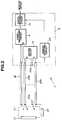
- Figs. 1 through 5show the first embodiment of this invention, of which Fig. 1 is a block diagram showing the overall construction of an endoscope apparatus; Fig. 2 is a block diagram showing the construction of an essential part of the electric circuit of the endoscope apparatus; Fig. 3 is a block diagram, partly consisting of a circuit diagram, showing in detail a humidity sensor and a water-leakage detecting circuit; Fig. 4 is a plan view showing an example of the humidity-sensor structure; and Fig. 5 is a sectional view showing another example of the humidity-sensor structure.
- the main section of an endoscope apparatus 1is composed of an endoscope 2, a light-source section 3 for supplying the endoscope 2 with illuminating light, an endoscope controller 5 containing a video-processing circuit 4 for signal processing, etc., and a monitor 6 for displaying an image of an object, etc.
- the endoscope 2is composed of a long and narrow inserting section 7, an operating section 8 formed at the rear end of the inserting section 7, and a universal cord 9 extending outwardly from the operating section 8.
- a light guide 11Passed through the inserting section 7 and the universal cord 9 is a light guide 11 for transmitting light; by connecting a connector 12 attached to the end of the universal cord 9 to the endoscope controller 5, light is supplied form the light-source section 3.
- White light emitted from a lamp 13is condensed by a condenser lens 14 and applied to the inlet-side end surface of the light guide 11. The light is then transmitted through the light guide 11 to a tip section 15 of the endoscope 2, where it is emitted from the outlet-side end surface of the light guide to illuminate an object in front.
- An optical image of the object being illuminatedis formed on a solid-state image sensing device (hereinafter abbreviated as "SID") 17, such as a CCD, by an objective optical system 16 provided in the tip section 15, the SID 17 being arranged in the focal plane of this optical system.
- the SID 17is covered with a leakage-proof member 21 provided inside the tip section 15.
- the optical image formed on the image-forming surface of the SID 17is photoelectrically converted by the SID 17 into an electric signal, which is transmitted to the video-processing circuit 4 through an SID-output-signal transmission cable 18, which serves as a signal line.
- the SID 17is connected to a driving circuit 10 through an SID drive cable 23 which serves as a signal line.
- coaxial cables or shielded cablesare employed for the SID-output-signal transmission cable 18 and for the SID drive cable 23 for the purposes of reducing unnecessary radiational noise from the cables, preventing circuit malfunction due to the influence of external noises, mitigating distortion of the transmission waveform, etc.
- the video-processing circuit 4converts the electric signal into a standard video signal, which is transmitted through a superimposing circuit 19 and displayed as an object image on a screen display section 20 of the monitor 6.
- a humidity sensor 22Arranged in the vicinity of the leakage-proof member 21 is a humidity sensor 22 for detecting water leakage, humidity, etc. on the outside of the leakage-proof member 21.
- the humidity sensor 22is connected to a leakage detecting circuit 24 in the controller 5 through the SID drive cable 23, which passes through the inserting section 7 and the universal cord 9. Based on the output of the humidity sensor 22, the leakage detecting circuit 24 outputs a detection signal indicating whether any water has been detected.
- This detection signalis supplied to the superimposing circuit 19, where it is superimposed on the output signal from the video-processing circuit 4 and then supplied to the monitor 6; when some water has been detected, a comment: "LEAKAGE DETECTED” or the like is displayed at the bottom on the left-hand side of the display screen of the monitor 6, or a display means (not shown) which is provided in the controller 5 gives a warning display.
- the leakage detectionmay also be notified by generating a warning sound or by simultaneously generating a visual display like a monitor display and a warning sound.
- any water or humidity which has entered the tip section of the endoscope 2is adsorbed or condensed on the surface of the humidity sensor 22, thereby changing the resistance value of the humidity sensor.
- the humidity sensor 22is connected in parallel to a capacitor 26 for removing noises, one end of which capacitor is connected to a shielded conductor which is among the cables constituting the SID drive cable 23 and which is not transmitting any signal, with the other end of the capacitor 26 being grounded.
- the SID drive cable 23is composed of a plurality of cables 23a, ......, 23g and 23h.
- the signals to be transmitted therethroughinclude an SID vertical drive signal, an SID horizontal drive signal, an SID power source signal, etc.
- the leakage detecting circuit 24employs an AC power source 31 as its power source, to which is connected a resistor 32 for detecting the resistance value of the humidity sensor 22 through voltage division. Because of the high impedance of the resistance value of the humidity sensor 22, the point of measurement, x, exhibits a high impedance.
- the cables in the electronic endoscopehave a long length of, for example, 3 to 7m and, in the case of medical applications, in particular, a peripheral apparatus constituting a disturbance source, such as a high-frequency knife, is used with the endoscope apparatus, so that when used under a high-impedance condition, the signal transmission line for the humidity sensor is influenced by disturbance noise, resulting in circuit malfunction.
- a capacitor 33 serving as a terminator meansis connected.
- the above-mentioned point of measurement xis connected to a rectifier-type detection circuit 34, which is composed of a diode 38, a resistor 39, and a capacitor 40 one end of which is grounded.
- the signal level output from the rectifier-type detection circuit 34is compared with a reference signal level 36 by means of a comparator 35 using an operation amplifier, etc., and a signal indicating whether humidity, etc. has been detected is supplied to the superimposing circuit 19.
- a shielded conductorconsisting of a coaxial cable is used as the transmission line for the signal from the humidity sensor 22.
- the impedance conditionis close to open circuit.
- the driving frequency of the vertical drive signalis 15.7 (kHz), which is lower than that of the horizontal drive signal, so that even without the capacitor 26 in the endoscope tip section 15, no bad influence is generated from the viewpoint of practical use due to the terminal capacity (approximately 1000 PF) inside the SID 17, such as the CCD.
- the humidity sensor shown in Fig. 4includes an insulating substrate 51 made of polyimide, glass, ceramics, epoxy or the like, comb-like electrode patterns 52 and 53 arranged alternately on the insulating substrate 51, and a humidity-sensitive resistor coating 54 applied to these electrode patterns.
- the humidity-sensitive resistor coating 54consists of a swellable high-molecular film containing a conductor material such as carbon particles or the like, and is adapted to vary the inter-electrode resistance value in accordance with the changes in the swelling condition at the time of moisture absorption and dehumidification. Even without the humidity-sensitive resistor coating 54, this humidity sensor provides a satisfactory sensitivity by increasing the pitch of the arrangement of the electrode patterns 52 and 53.
- the humidity sensor shown in Fig. 5includes a porous substrate 56, which is made of a glass, a ceramic material or the like which contains a hygroscopic electrolyte such as lithium chloride, the porous substrate 56 being placed between electrodes 57 and 58.
- This humidity sensoris also capable of sensing changes in electric resistance caused by moisture absorption and dehumidification.
- the first embodimentit is possible to transmit signals from a detection means provided in the tip section, such as a humidity sensor, to the side of the apparatus operating section without requiring an of increase the diameter of the endoscope inserting section, and to reliably notify the operator of the detection results obtained by the detection means.
- a detection means provided in the tip sectionsuch as a humidity sensor
- a temperature sensor, a pressure sensor, a gas sensor, a biosensor, a magnetometric sensor, a gravity sensor or the likeis used instead of the humidity sensor, there is no need to provide a dedicated signal transmission line for such a sensor, so that the detection of physical or chemical changes by a detecting device can be effected without having to augment the diameter of the inserting section of the endoscope.
- the above-mentioned sensorswill be described one by one.
- a pressure sensorgenerally consists of a resistance-wire strain gage or the like.
- the pressure sensor structureis not limited to the one described above.
- a temperature sensor based, for example, on a resistance thermometer bulbutilizes the fact that the resistance value of a metal wire changes in accordance with the ambient temperature.
- a temperature sensor using a thermocoupledetects a thermo-electromotive force at the interface between two different metals, which force changes in accordance with the ambient temperature.
- the construction of the temperature sensoris not limited to these two types.
- the magnetometric sensorthere is one type based on a magnetic resistor type and another type based on a Hall element.
- a magnetic resistor typeany change in the carrier movement between electrodes on either side of a semiconductor when an electric field is applied thereto is detected as a resistance value.
- the latter typealso utilizes the carrier movement for detect resistance value.
- the construction of the magnetic sensoris not restricted to these two types
- the gas sensorfunctions as follows: any gas molecules adsorbed on a semiconductor surface consisting of a metal oxide cause a change in electron concentration due to electron exchange between the gas molecules and the semiconductor. This change is extracted as a change in the value of electric resistance.
- the construction of the gas sensoris not limited to the one described above.
- the biosensorhas a functional film consisting of a biosubstance.
- This functional filmreacts with a particular chemical substance, heat is generated along with a change in ion concentration, which change is converted to an electric signal by one of the sensors described above.
- This biosensoris currently being used as a sensor for detecting vital reactions, for example, as an oxygen sensor or an immunity sensor utilizing antigen-antibody reactions.
- the construction of the biosensoris not restricted to the type described above.
- the gravity sensorcomprises a weight which is placed on a piezoelectric element formed of quartz or ceramics sandwiched between two electrodes.
- the sensoris adapted to convert a change in gravity to a change in voltage.
- this sensorcan be used in the detection of an attitude of something in a static condition (i.e., whether it is set horizontal, vertical, reversed, etc.). It may be used, for example, in the attitude control of an endoscope.
- the construction of the gravity sensoris not limited to the one described above.
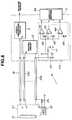
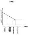
- Figs. 6 and 7show the second embodiment of the present invention, of which Fig. 6 is a block diagram, partly consisting of a circuit diagram, illustrating in detail a humidity sensor and a water-leakage detecting circuit; and Fig. 7 is a graph showing the relationship between humidity-sensor output and humidity.
- the second embodimentdiffers from the first one, described above, in the following point:
- the signal source for driving the humidity sensoris a DC power source 41.
- the humidity sensor outputobtained at the point of measurement x, is supplied to comparators 42, 43 and 44, where it is compared with different reference levels 45, 46 and 47. As a result, it is possible, as shown in Fig. 7, to distinguish the condition around the sensor between "normal”, “high humidity”, “condensation” and “submergence'.
- the detection signals from the comparators 42, 43 and 44are displayed in a display section 48 which is different from the monitor 6 (see Fig. 6) and which is provided in the endoscope controller 5, giving a warning to the observer.
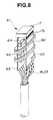
- Fig. 8is a perspective view showing a tip-section unit 61 serving as the image-sensing unit of the third embodiment of the present invention.
- a description of those components of the third embodiment which are the same as those of the first and second embodimentswill be omitted, and only those points which differ from the first and second embodiments will be described.
- the tip-section unit 61has a structure as shown in Fig. 8. That is, the SID 17 is electrically connected to substrates 62 and 63 through lead feet 17a protruding from that surface thereof which is on the opposite side of its image formation surface. A capacitor 64 and an IC 65, which serve to supply electric power to the SID 17, are arranged on that surface of the substrate 63 which faces the substrate 62.
- the IC 65functions, for example, as a buffer for amplifying the output of the SID 17 and driving the cables, and as a generator of various bias voltages, such as the SUB voltage and the gate voltages to be supplied to the SID 17.
- the cables 18 and 23are connected to the substrates 62 and 63.
- a humidity sensor 22 in the form of a long and narrow stripis wound around the above-described tip-section unit 61 at a fixed pitch.
- This humidity sensor 22comprises a long and narrow bendable substrate, for example, a flexible substrate, and two long and narrow electrodes arranged close to each other on this substrate. It is not the comb-like type shown in Fig. 4 but has a parallel pattern in which the electrodes are closely arranged. It is based on the same detection principle as the one described above, detecting humidity from a change in impedance caused by any water adhering to the space between the electrodes.
- This third embodimentprovides substantially the same effect as the ones described above and, further, makes it possible to detect water leakage into the tip-section unit 61 regardless of from what direction it has occurred, thereby improving the detection reliability.
- Fig. 9is an enlarged perspective view showing an SID 17 according to the fourth embodiment of the present invention.
- the essential section of the SID 17 of the fourth embodimentis composed of a package 68 and a sensor chip 69 arranged thereon.
- the sensor chip 69 and the package 68are electrically connected to each other by connecting electrical contacts 75 and 76, respectively provided on them, to each other through bonding wires 71.
- the output of this SIDis emitted from a plurality of lead feet 17a protruding from that surface of the package 68 which is on the opposite side of the sensor chip 69.
- the sensor chip 69includes an image area 72 consisting of a plurality of photosensitive elements, such as photodiodes, arranged plain-like on the image forming surface, a horizontal CCD register 73 provided on one side of the image area 72, and an output amplifier 74 for voltage-converting photoelectric charge signals, with the plurality of electrical contacts 75 connecting to the above-mentioned bonding wires being arranged at one end of this sensor chip.
- a sensor 22 for detecting humidity, etc.is integrally formed on the sensor chip 69, at a position, for example, near the output amplifier 74.
- the fourth embodimentconstructed as described above, provides substantially the same effect as the first to third embodiments. Further, since there is no need to form the detection means as a separate unit, the assembly process is simplified and the assembly time is reduced.
- the present inventionis not limited to the use of one type of sensor in an endoscope apparatus. It is of course also possible to construct an endoscope of substantially the same structure having a plurality of types of sensors.
Landscapes
- Health & Medical Sciences (AREA)
- Life Sciences & Earth Sciences (AREA)
- Surgery (AREA)
- Biomedical Technology (AREA)
- Medical Informatics (AREA)
- Optics & Photonics (AREA)
- Pathology (AREA)
- Radiology & Medical Imaging (AREA)
- Biophysics (AREA)
- Engineering & Computer Science (AREA)
- Physics & Mathematics (AREA)
- Heart & Thoracic Surgery (AREA)
- Nuclear Medicine, Radiotherapy & Molecular Imaging (AREA)
- Molecular Biology (AREA)
- Animal Behavior & Ethology (AREA)
- General Health & Medical Sciences (AREA)
- Public Health (AREA)
- Veterinary Medicine (AREA)
- Endoscopes (AREA)
- Instruments For Viewing The Inside Of Hollow Bodies (AREA)
- Arrangements For Transmission Of Measured Signals (AREA)
Description
Claims (19)
- An electronic endoscope apparatus which includes aninserting section (7) extending from an operating section(8), said electronic endoscope apparatus comprising:detecting means (22) for detecting physical andchemical changes provided at a tip of the inserting section(7);indicating means (6; 48) for indicating the detectionresults of said detecting means (22);image-sensing means (17) provided at the tip of saidinserting section (7);a signal line (18, 23) connected to said image-sensingmeans (17); anda transmission line (23h) for transmitting signalsfrom said detecting means (22),
characterized in thatsaid transmission line (23h) being a shielded conductor which isamong the cables constituting the signal line (18, 23). - An electronic endoscope apparatus according toclaim 1,
wherein said detecting means (22; 87) is a humiditydetecting means. - An electronic endoscope apparatus according toclaim 2,
wherein said humidity detecting (22) means includes:an insulating substrate (51); andtwo electrode patterns (52, 53) arranged close toeach other on said insulating substrate (51). - An electronic endoscope apparatus according toclaim 3,
wherein said two electrode patterns (52, 53) are formedalternately in a comb-like fashion. - An electronic endoscope apparatus according toclaim 3 or 4,
wherein said two electrode patterns (52, 53) are coveredwith a moisture-sensitive resistor coating (54). - An electronic endoscope apparatus according toclaim 5,
wherein said insulating substrate is in the form of a longand narrow strip, said electrode patterns being in the formof two substantially parallel lines arranged close to eachother on said insulating substrate. - An electronic endoscope apparatus according toclaim 2,
wherein said humidity detecting means (22) includes:a porous substrate (56) containing a hygroscopicelectrolyte; andtwo electrodes (57, 58) between which said poroussubstrate (56) is interposed. - An electronic endoscope apparatus according toclaim 2,
wherein said image-sensing means (17) is an image-sensingunit, said humidity detecting means (22, 94) being providedin the vicinity of this image-sensing unit. - An electronic endoscope apparatus according toclaim 8,
wherein said humidity detecting means (22) is provided in the vicinity of said image-sensing unit (17) in such a wayas to cover said image-sensing unit. - An electronic endoscope apparatus according toclaim 8,
wherein said humidity detecting means (22) includes abendable insulating substrate formed as a long and narrowstrip, and electrode patterns in the form of twosubstantially parallel lines arranged close to each otheron said insulating substrate, and is wound around saidimage-sensing unit (17, 62, 63) at a substantially fixedpitch. - An electronic endoscope apparatus according to any ofclaims 1 to 10,
wherein said indicating means consists of at least either avisual display means (6) or an auditory notifying means. - An electronic endoscope apparatus according to any ofclaims 1 to 11,
wherein said indicating means (48) gives a graduateddisplay of the detecting condition of said humiditydetecting means (22). - An electronic endoscope apparatus according toclaim 1,
wherein said detecting means (22, 87) consists of one ofthe following means:a temperature detecting means,a pressure detecting means,a gas detecting means,a bio detecting means for detecting vital reactionsasan oxygen sensor or an immunity sensor utilizingantigen-antibody reactions,a magnetic detecting means, ora gravity detecting means for converting the change ingravity to a change in voltage. - An electronic endoscope apparatus according to any ofclaims 1 to 13,
wherein said signal line (18, 23) is a shielded cable or acoaxial cable, said transmission line constituting ashielding line of said shielded cable or an armoring wireof said coaxial cable. - An electronic endoscope apparatus according toclaim 1,
wherein said image-sensing means (17) is a solid-stateimage sensing device, said signal line constituting avertical-drive-signal cable of said solid-state imagesensing device (17). - An electronic endoscope apparatus according toclaim 1,
wherein said transmission line (23) is connected to an AC-typeterminator means (33). - An electronic endoscope apparatus according toclaim 1,
wherein said detecting means (22) is provided integrallywith said image-sensing means (17). - An electronic endoscope apparatus according toclaim 1,
wherein said humidity detecting means (22) has twoelectrodes arranged close to each other. - An electronic endoscope apparatus according toclaim 1,
wherein said indicating means (6; 48) is at least either avisual display means or an auditory notifying means.
Applications Claiming Priority (4)
| Application Number | Priority Date | Filing Date | Title |
|---|---|---|---|
| JP104670/92 | 1992-04-23 | ||
| JP10467092 | 1992-04-23 | ||
| JP30981/93 | 1993-02-19 | ||
| JP03098193AJP3302074B2 (en) | 1992-04-23 | 1993-02-19 | Endoscope device |
Publications (2)
| Publication Number | Publication Date |
|---|---|
| EP0566861A1 EP0566861A1 (en) | 1993-10-27 |
| EP0566861B1true EP0566861B1 (en) | 1998-06-10 |
Family
ID=26369437
Family Applications (1)
| Application Number | Title | Priority Date | Filing Date |
|---|---|---|---|
| EP93104150AExpired - LifetimeEP0566861B1 (en) | 1992-04-23 | 1993-03-15 | Endoscope apparatus |
Country Status (4)
| Country | Link |
|---|---|
| US (1) | US5402769A (en) |
| EP (1) | EP0566861B1 (en) |
| JP (1) | JP3302074B2 (en) |
| DE (1) | DE69319018T2 (en) |
Cited By (2)
| Publication number | Priority date | Publication date | Assignee | Title |
|---|---|---|---|---|
| CN100525699C (en)* | 2004-09-27 | 2009-08-12 | 奥林巴斯株式会社 | Bending control device |
| CN105596111A (en)* | 2016-02-03 | 2016-05-25 | 黑龙江省畜牧研究所 | Device used for detecting sheep before artificial insemination and detection method adopting same |
Families Citing this family (76)
| Publication number | Priority date | Publication date | Assignee | Title |
|---|---|---|---|---|
| US6184923B1 (en)* | 1994-11-25 | 2001-02-06 | Olympus Optical Co., Ltd. | Endoscope with an interchangeable distal end optical adapter |
| US5830124A (en)* | 1995-05-18 | 1998-11-03 | Fuji Photo Optical Co., Ltd. | Guide structure for electronic endoscope systems |
| WO1998004185A1 (en)* | 1996-07-29 | 1998-02-05 | Karl Storz Gmbh & Co. | Endoscope with at least one sensing and recording device |
| US5797838A (en)* | 1996-09-13 | 1998-08-25 | Colin Corporation | Physical-information-image displaying apparatus |
| US5785652A (en)* | 1996-09-13 | 1998-07-28 | Colin Corporation | Physical-information abnormality informing endoscope |
| DE19750089B4 (en)* | 1997-11-12 | 2005-02-17 | Gerhard Benker | Stromflußaktuatorenendoskop |
| JP3370916B2 (en)* | 1997-12-11 | 2003-01-27 | 富士写真光機株式会社 | An electronic endoscope device that displays a display without a scope |
| US6419626B1 (en)* | 1998-08-12 | 2002-07-16 | Inbae Yoon | Surgical instrument endoscope with CMOS image sensor and physical parameter sensor |
| US7951071B2 (en)* | 1999-06-02 | 2011-05-31 | Tyco Healthcare Group Lp | Moisture-detecting shaft for use with an electro-mechanical surgical device |
| US6579243B2 (en)* | 2000-03-02 | 2003-06-17 | Scimed Life Systems, Inc. | Catheter with thermal sensor for detection of vulnerable plaque |
| IL156876A0 (en)* | 2001-01-11 | 2004-02-08 | Given Imaging Ltd | Device and system for in-vivo procedures |
| JP4776793B2 (en)* | 2001-03-08 | 2011-09-21 | オリンパス株式会社 | Endoscope device |
| US6951536B2 (en)* | 2001-07-30 | 2005-10-04 | Olympus Corporation | Capsule-type medical device and medical system |
| US20030171655A1 (en)* | 2002-03-08 | 2003-09-11 | Newman Richard W. | Combination otoscope |
| US7787939B2 (en)* | 2002-03-18 | 2010-08-31 | Sterling Lc | Miniaturized imaging device including utility aperture and SSID |
| US20060146172A1 (en)* | 2002-03-18 | 2006-07-06 | Jacobsen Stephen C | Miniaturized utility device having integrated optical capabilities |
| US7591780B2 (en)* | 2002-03-18 | 2009-09-22 | Sterling Lc | Miniaturized imaging device with integrated circuit connector system |
| US8614768B2 (en)* | 2002-03-18 | 2013-12-24 | Raytheon Company | Miniaturized imaging device including GRIN lens optically coupled to SSID |
| US7133063B2 (en)* | 2002-07-16 | 2006-11-07 | Fujinon Corporation | Electronic endoscope apparatus which superimposes signals on power supply |
| US7591783B2 (en) | 2003-04-01 | 2009-09-22 | Boston Scientific Scimed, Inc. | Articulation joint for video endoscope |
| US20040199052A1 (en) | 2003-04-01 | 2004-10-07 | Scimed Life Systems, Inc. | Endoscopic imaging system |
| US8118732B2 (en) | 2003-04-01 | 2012-02-21 | Boston Scientific Scimed, Inc. | Force feedback control system for video endoscope |
| US20050245789A1 (en) | 2003-04-01 | 2005-11-03 | Boston Scientific Scimed, Inc. | Fluid manifold for endoscope system |
| US7578786B2 (en) | 2003-04-01 | 2009-08-25 | Boston Scientific Scimed, Inc. | Video endoscope |
| JP4542370B2 (en)* | 2004-05-24 | 2010-09-15 | オリンパス株式会社 | Intra-subject introduction device |
| WO2006039522A2 (en) | 2004-09-30 | 2006-04-13 | Boston Scientific Scimed, Inc. | Adapter for use with digital imaging medical device |
| US7479106B2 (en) | 2004-09-30 | 2009-01-20 | Boston Scientific Scimed, Inc. | Automated control of irrigation and aspiration in a single-use endoscope |
| JP2008514363A (en) | 2004-09-30 | 2008-05-08 | ボストン サイエンティフィック リミテッド | Multifunctional endoscope system for use in electrosurgical applications |
| US7241263B2 (en) | 2004-09-30 | 2007-07-10 | Scimed Life Systems, Inc. | Selectively rotatable shaft coupler |
| US7597662B2 (en) | 2004-09-30 | 2009-10-06 | Boston Scientific Scimed, Inc. | Multi-fluid delivery system |
| EP1799096A2 (en) | 2004-09-30 | 2007-06-27 | Boston Scientific Scimed, Inc. | System and method of obstruction removal |
| US8083671B2 (en) | 2004-09-30 | 2011-12-27 | Boston Scientific Scimed, Inc. | Fluid delivery system for use with an endoscope |
| EP1658819B1 (en) | 2004-11-18 | 2008-01-02 | BrainLAB AG | Transparent marker cover |
| US8179428B2 (en) | 2004-11-24 | 2012-05-15 | Fujinon Corporation | Imaging apparatus for electronic endoscope and electronic endoscope |
| JP2006288800A (en)* | 2005-04-12 | 2006-10-26 | Pentax Corp | Electronic endoscope and electronic endoscope system |
| US20060253028A1 (en)* | 2005-04-20 | 2006-11-09 | Scimed Life Systems, Inc. | Multiple transducer configurations for medical ultrasound imaging |
| US20060252990A1 (en)* | 2005-05-06 | 2006-11-09 | Melissa Kubach | Systems and methods for endoscope integrity testing |
| US8109871B2 (en)* | 2005-05-06 | 2012-02-07 | Minntech Corporation | Endoscope integrity tester including context-sensitive compensation and methods of context-sensitive integrity testing |
| US20070060791A1 (en)* | 2005-05-06 | 2007-03-15 | Melissa Kubach | Computer systems and software for operating an endoscope integrity tester |
| US20060252991A1 (en)* | 2005-05-06 | 2006-11-09 | Melissa Kubach | Systems and methods for endoscope integrity testing |
| US7846107B2 (en) | 2005-05-13 | 2010-12-07 | Boston Scientific Scimed, Inc. | Endoscopic apparatus with integrated multiple biopsy device |
| US8097003B2 (en) | 2005-05-13 | 2012-01-17 | Boston Scientific Scimed, Inc. | Endoscopic apparatus with integrated variceal ligation device |
| US8052597B2 (en) | 2005-08-30 | 2011-11-08 | Boston Scientific Scimed, Inc. | Method for forming an endoscope articulation joint |
| JP4855771B2 (en)* | 2005-12-20 | 2012-01-18 | オリンパスメディカルシステムズ株式会社 | In-vivo image capturing apparatus and in-vivo image capturing system |
| JP4611193B2 (en)* | 2005-12-27 | 2011-01-12 | オリンパスメディカルシステムズ株式会社 | Endoscope device |
| US7967759B2 (en) | 2006-01-19 | 2011-06-28 | Boston Scientific Scimed, Inc. | Endoscopic system with integrated patient respiratory status indicator |
| US8888684B2 (en) | 2006-03-27 | 2014-11-18 | Boston Scientific Scimed, Inc. | Medical devices with local drug delivery capabilities |
| US8202265B2 (en) | 2006-04-20 | 2012-06-19 | Boston Scientific Scimed, Inc. | Multiple lumen assembly for use in endoscopes or other medical devices |
| US7955255B2 (en) | 2006-04-20 | 2011-06-07 | Boston Scientific Scimed, Inc. | Imaging assembly with transparent distal cap |
| US20080139884A1 (en)* | 2006-12-06 | 2008-06-12 | Myers William D | Medical examination system with endoscopic probe |
| DE102008018931A1 (en) | 2007-04-17 | 2008-11-13 | Gyrus ACMI, Inc., Southborough | Light source power based on a predetermined detected condition |
| US7835074B2 (en) | 2007-06-05 | 2010-11-16 | Sterling Lc | Mini-scope for multi-directional imaging |
| US7969659B2 (en)* | 2008-01-11 | 2011-06-28 | Sterling Lc | Grin lens microscope system |
| US20090287048A1 (en)* | 2008-05-16 | 2009-11-19 | Sterling Lc | Method and apparatus for imaging within a living body |
| WO2009155441A2 (en) | 2008-06-18 | 2009-12-23 | Sterling Lc | Transparent endoscope head defining a focal length |
| JP5356742B2 (en) | 2008-07-10 | 2013-12-04 | ラピスセミコンダクタ株式会社 | Semiconductor device, semiconductor device manufacturing method, and semiconductor package manufacturing method |
| WO2010014792A2 (en) | 2008-07-30 | 2010-02-04 | Sterling Lc | Method and device for incremental wavelength variation to analyze tissue |
| WO2010053916A2 (en) | 2008-11-04 | 2010-05-14 | Sterling Lc | Method and device for wavelength shifted imaging |
| US8512232B2 (en)* | 2009-09-08 | 2013-08-20 | Gyrus Acmi, Inc. | Endoscopic illumination system, assembly and methods for staged illumination of different target areas |
| WO2011041730A2 (en) | 2009-10-01 | 2011-04-07 | Jacobsen Stephen C | Light diffusion apparatus |
| WO2011041728A2 (en) | 2009-10-01 | 2011-04-07 | Jacobsen Stephen C | Needle delivered imaging device |
| WO2011041720A2 (en) | 2009-10-01 | 2011-04-07 | Jacobsen Stephen C | Method and apparatus for manipulating movement of a micro-catheter |
| US8828028B2 (en) | 2009-11-03 | 2014-09-09 | Raytheon Company | Suture device and method for closing a planar opening |
| CN102288609A (en)* | 2011-07-18 | 2011-12-21 | 徐州奥奇光电科技有限公司 | On-line monitoring intelligent flame endoscope |
| JP5298259B1 (en)* | 2011-09-22 | 2013-09-25 | オリンパスメディカルシステムズ株式会社 | Endoscope |
| JP5762244B2 (en)* | 2011-10-18 | 2015-08-12 | 富士フイルム株式会社 | Endoscope device |
| EP2674095A4 (en)* | 2011-12-07 | 2015-06-03 | Olympus Medical Systems Corp | ELECTRONIC ENDOSCOPE |
| JP2013118937A (en)* | 2011-12-07 | 2013-06-17 | Fujifilm Corp | Electronic endoscope, method for manufacturing the same, and electronic endoscope system |
| CN104869883B (en) | 2012-10-23 | 2018-07-27 | 波士顿科学国际有限公司 | Signal transmission components used with medical devices |
| DE102012220372B4 (en)* | 2012-11-08 | 2016-10-06 | Digital Endoscopy Gmbh | Endoscope and pressure test procedure for an endoscope |
| JP6242126B2 (en)* | 2013-09-04 | 2017-12-06 | オリンパス株式会社 | Endoscope |
| EP3247253A4 (en)* | 2015-01-23 | 2018-08-01 | Inspectron Inc. | Video inspection device |
| US10034538B1 (en) | 2017-05-05 | 2018-07-31 | Sauder Woodworking Co. | Height-adjustable work surface assembly |
| JP7034677B2 (en)* | 2017-11-17 | 2022-03-14 | ソニー・オリンパスメディカルソリューションズ株式会社 | Medical circuit boards and medical devices |
| DE102019103287A1 (en)* | 2019-02-11 | 2020-08-13 | Olympus Winter & Ibe Gmbh | Device for determining a parasitic resistance in video endoscopes |
| US11937984B2 (en)* | 2020-08-25 | 2024-03-26 | GE Precision Healthcare LLC | Active ingress detection system for medical probes |
Family Cites Families (13)
| Publication number | Priority date | Publication date | Assignee | Title |
|---|---|---|---|---|
| JPS55136030A (en)* | 1979-04-06 | 1980-10-23 | Olympus Optical Co | Photographing device for endoscope |
| DE3231422A1 (en)* | 1982-08-24 | 1984-03-01 | Murata Manufacturing Co., Ltd., Nagaokakyo, Kyoto | Dew-point thimble |
| FR2543184B1 (en)* | 1983-03-21 | 1985-08-02 | Pomagalski Sa | LARGE-RANGE TELECABINE |
| JPS6069620A (en)* | 1983-09-26 | 1985-04-20 | Olympus Optical Co Ltd | Endoscope |
| JPS61253993A (en)* | 1985-05-07 | 1986-11-11 | Nippon Hoso Kyokai <Nhk> | Transmission method of stereoscopic television image signal |
| US4803562A (en)* | 1986-06-20 | 1989-02-07 | Olympus Optical Co., Ltd. | Image sensing apparatus |
| US4793182A (en)* | 1987-06-02 | 1988-12-27 | Djorup Robert Sonny | Constant temperature hygrometer |
| US5088492A (en)* | 1987-09-16 | 1992-02-18 | Olympus Optical Co., Ltd. | Radioactive ray detecting endoscope |
| US4995396A (en)* | 1988-12-08 | 1991-02-26 | Olympus Optical Co., Ltd. | Radioactive ray detecting endoscope |
| JP2510299B2 (en)* | 1989-03-22 | 1996-06-26 | オリンパス光学工業株式会社 | Electronic endoscope system |
| US4993405A (en)* | 1989-05-15 | 1991-02-19 | Olympus Optical Co., Ltd. | Imaging apparatus |
| US5060632A (en)* | 1989-09-05 | 1991-10-29 | Olympus Optical Co., Ltd. | Endoscope apparatus |
| JP3003942B2 (en)* | 1990-02-13 | 2000-01-31 | オリンパス光学工業株式会社 | Endoscope |
- 1993
- 1993-02-19JPJP03098193Apatent/JP3302074B2/ennot_activeExpired - Fee Related
- 1993-03-11USUS08/029,581patent/US5402769A/ennot_activeExpired - Lifetime
- 1993-03-15DEDE69319018Tpatent/DE69319018T2/ennot_activeExpired - Fee Related
- 1993-03-15EPEP93104150Apatent/EP0566861B1/ennot_activeExpired - Lifetime
Cited By (3)
| Publication number | Priority date | Publication date | Assignee | Title |
|---|---|---|---|---|
| CN100525699C (en)* | 2004-09-27 | 2009-08-12 | 奥林巴斯株式会社 | Bending control device |
| CN105596111A (en)* | 2016-02-03 | 2016-05-25 | 黑龙江省畜牧研究所 | Device used for detecting sheep before artificial insemination and detection method adopting same |
| CN105596111B (en)* | 2016-02-03 | 2017-05-24 | 黑龙江省畜牧研究所 | Device used for detecting sheep before artificial insemination and detection method adopting same |
Also Published As
| Publication number | Publication date |
|---|---|
| JPH06157A (en) | 1994-01-11 |
| EP0566861A1 (en) | 1993-10-27 |
| DE69319018T2 (en) | 1999-02-18 |
| US5402769A (en) | 1995-04-04 |
| JP3302074B2 (en) | 2002-07-15 |
| DE69319018D1 (en) | 1998-07-16 |
Similar Documents
| Publication | Publication Date | Title |
|---|---|---|
| EP0566861B1 (en) | Endoscope apparatus | |
| US5965880A (en) | Tactile opto-electronic pressure sensor | |
| JP3165670B2 (en) | Probe with pods for tissue type recognition | |
| US10281710B2 (en) | Imaging module and endoscope apparatus each having a flexible substrate divided into different regions where a chip having a transmission buffer and a drive signal cable are connected to the different regions | |
| RU2096992C1 (en) | Photosensor device | |
| US20080067895A1 (en) | Capacitive micromachined ultrasonic transducer and production method of same | |
| WO2014098363A1 (en) | Skin condition measuring device for smartphone | |
| EP3050491B1 (en) | Endoscope device | |
| US10912448B2 (en) | Cable connection structure, imaging module, and endoscope | |
| JP2002512541A (en) | Built-in tubular device for tissue discriminating probe | |
| KR102005813B1 (en) | Electrostatic touch assembly of light source device for endoscope and endoscope system including the same | |
| KR101265568B1 (en) | Bio sensing device | |
| JPS63315024A (en) | Endoscope | |
| AU2004294915B2 (en) | A self-condensing pH sensor | |
| US20170071453A1 (en) | Cable connection structure and endoscope apparatus | |
| JP2003038423A (en) | Medical treatment device | |
| Rawlings et al. | Plastic pH electrodes for the measurement of gastrointestinal pH. | |
| WO2015088145A1 (en) | Apparatus for measuring condition of object | |
| CN219374586U (en) | Detection apparatus for endoscope image processing system | |
| WO2013147351A1 (en) | Biosensor | |
| KR102564069B1 (en) | Affected condition monitoring device, and dressing for condition monitoring comprising the same | |
| JP7032768B2 (en) | Urine test piece and urine test system | |
| WO2002022007A2 (en) | Chemical sensing instrument and related method of use | |
| JP2009119116A (en) | X-ray image acquisition device | |
| JPH0380827A (en) | Endoscope device |
Legal Events
| Date | Code | Title | Description |
|---|---|---|---|
| PUAI | Public reference made under article 153(3) epc to a published international application that has entered the european phase | Free format text:ORIGINAL CODE: 0009012 | |
| 17P | Request for examination filed | Effective date:19930415 | |
| AK | Designated contracting states | Kind code of ref document:A1 Designated state(s):DE FR GB | |
| 17Q | First examination report despatched | Effective date:19950103 | |
| GRAG | Despatch of communication of intention to grant | Free format text:ORIGINAL CODE: EPIDOS AGRA | |
| GRAG | Despatch of communication of intention to grant | Free format text:ORIGINAL CODE: EPIDOS AGRA | |
| GRAH | Despatch of communication of intention to grant a patent | Free format text:ORIGINAL CODE: EPIDOS IGRA | |
| GRAH | Despatch of communication of intention to grant a patent | Free format text:ORIGINAL CODE: EPIDOS IGRA | |
| GRAA | (expected) grant | Free format text:ORIGINAL CODE: 0009210 | |
| AK | Designated contracting states | Kind code of ref document:B1 Designated state(s):DE FR GB | |
| ET | Fr: translation filed | ||
| REF | Corresponds to: | Ref document number:69319018 Country of ref document:DE Date of ref document:19980716 | |
| PLBE | No opposition filed within time limit | Free format text:ORIGINAL CODE: 0009261 | |
| 26N | No opposition filed | ||
| REG | Reference to a national code | Ref country code:GB Ref legal event code:IF02 | |
| PGFP | Annual fee paid to national office [announced via postgrant information from national office to epo] | Ref country code:GB Payment date:20090311 Year of fee payment:17 | |
| PGFP | Annual fee paid to national office [announced via postgrant information from national office to epo] | Ref country code:DE Payment date:20090313 Year of fee payment:17 | |
| PGFP | Annual fee paid to national office [announced via postgrant information from national office to epo] | Ref country code:FR Payment date:20090316 Year of fee payment:17 | |
| GBPC | Gb: european patent ceased through non-payment of renewal fee | Effective date:20100315 | |
| REG | Reference to a national code | Ref country code:FR Ref legal event code:ST Effective date:20101130 | |
| PG25 | Lapsed in a contracting state [announced via postgrant information from national office to epo] | Ref country code:FR Free format text:LAPSE BECAUSE OF NON-PAYMENT OF DUE FEES Effective date:20100331 | |
| PG25 | Lapsed in a contracting state [announced via postgrant information from national office to epo] | Ref country code:DE Free format text:LAPSE BECAUSE OF NON-PAYMENT OF DUE FEES Effective date:20101001 | |
| PG25 | Lapsed in a contracting state [announced via postgrant information from national office to epo] | Ref country code:GB Free format text:LAPSE BECAUSE OF NON-PAYMENT OF DUE FEES Effective date:20100315 |