EP0564967B1 - Process and apparatus for the production of a filter having the form of a honeycomb - Google Patents
Process and apparatus for the production of a filter having the form of a honeycombDownload PDFInfo
- Publication number
- EP0564967B1 EP0564967B1EP93105310AEP93105310AEP0564967B1EP 0564967 B1EP0564967 B1EP 0564967B1EP 93105310 AEP93105310 AEP 93105310AEP 93105310 AEP93105310 AEP 93105310AEP 0564967 B1EP0564967 B1EP 0564967B1
- Authority
- EP
- European Patent Office
- Prior art keywords
- channels
- monolith
- dosing
- nozzles
- closed
- Prior art date
- Legal status (The legal status is an assumption and is not a legal conclusion. Google has not performed a legal analysis and makes no representation as to the accuracy of the status listed.)
- Expired - Lifetime
Links
Images
Classifications
- B—PERFORMING OPERATIONS; TRANSPORTING
- B28—WORKING CEMENT, CLAY, OR STONE
- B28B—SHAPING CLAY OR OTHER CERAMIC COMPOSITIONS; SHAPING SLAG; SHAPING MIXTURES CONTAINING CEMENTITIOUS MATERIAL, e.g. PLASTER
- B28B11/00—Apparatus or processes for treating or working the shaped or preshaped articles
- B28B11/003—Apparatus or processes for treating or working the shaped or preshaped articles the shaping of preshaped articles, e.g. by bending
- B28B11/006—Making hollow articles or partly closed articles
- B—PERFORMING OPERATIONS; TRANSPORTING
- B01—PHYSICAL OR CHEMICAL PROCESSES OR APPARATUS IN GENERAL
- B01D—SEPARATION
- B01D46/00—Filters or filtering processes specially modified for separating dispersed particles from gases or vapours
- B01D46/0001—Making filtering elements
- B—PERFORMING OPERATIONS; TRANSPORTING
- B01—PHYSICAL OR CHEMICAL PROCESSES OR APPARATUS IN GENERAL
- B01D—SEPARATION
- B01D46/00—Filters or filtering processes specially modified for separating dispersed particles from gases or vapours
- B01D46/24—Particle separators, e.g. dust precipitators, using rigid hollow filter bodies
- B01D46/2403—Particle separators, e.g. dust precipitators, using rigid hollow filter bodies characterised by the physical shape or structure of the filtering element
- B01D46/2418—Honeycomb filters
- B01D46/2422—Mounting of the body within a housing
- C—CHEMISTRY; METALLURGY
- C04—CEMENTS; CONCRETE; ARTIFICIAL STONE; CERAMICS; REFRACTORIES
- C04B—LIME, MAGNESIA; SLAG; CEMENTS; COMPOSITIONS THEREOF, e.g. MORTARS, CONCRETE OR LIKE BUILDING MATERIALS; ARTIFICIAL STONE; CERAMICS; REFRACTORIES; TREATMENT OF NATURAL STONE
- C04B38/00—Porous mortars, concrete, artificial stone or ceramic ware; Preparation thereof
- C04B38/0006—Honeycomb structures
- B—PERFORMING OPERATIONS; TRANSPORTING
- B01—PHYSICAL OR CHEMICAL PROCESSES OR APPARATUS IN GENERAL
- B01D—SEPARATION
- B01D46/00—Filters or filtering processes specially modified for separating dispersed particles from gases or vapours
- B01D46/24—Particle separators, e.g. dust precipitators, using rigid hollow filter bodies
- B01D46/2403—Particle separators, e.g. dust precipitators, using rigid hollow filter bodies characterised by the physical shape or structure of the filtering element
- B01D46/2418—Honeycomb filters
- B01D46/2451—Honeycomb filters characterized by the geometrical structure, shape, pattern or configuration or parameters related to the geometry of the structure
- B01D46/2455—Honeycomb filters characterized by the geometrical structure, shape, pattern or configuration or parameters related to the geometry of the structure of the whole honeycomb or segments
- B—PERFORMING OPERATIONS; TRANSPORTING
- B01—PHYSICAL OR CHEMICAL PROCESSES OR APPARATUS IN GENERAL
- B01D—SEPARATION
- B01D46/00—Filters or filtering processes specially modified for separating dispersed particles from gases or vapours
- B01D46/24—Particle separators, e.g. dust precipitators, using rigid hollow filter bodies
- B01D46/2403—Particle separators, e.g. dust precipitators, using rigid hollow filter bodies characterised by the physical shape or structure of the filtering element
- B01D46/2418—Honeycomb filters
- B01D46/2451—Honeycomb filters characterized by the geometrical structure, shape, pattern or configuration or parameters related to the geometry of the structure
- B01D46/247—Honeycomb filters characterized by the geometrical structure, shape, pattern or configuration or parameters related to the geometry of the structure of the cells
- B—PERFORMING OPERATIONS; TRANSPORTING
- B01—PHYSICAL OR CHEMICAL PROCESSES OR APPARATUS IN GENERAL
- B01D—SEPARATION
- B01D46/00—Filters or filtering processes specially modified for separating dispersed particles from gases or vapours
- B01D46/24—Particle separators, e.g. dust precipitators, using rigid hollow filter bodies
- B01D46/2403—Particle separators, e.g. dust precipitators, using rigid hollow filter bodies characterised by the physical shape or structure of the filtering element
- B01D46/2418—Honeycomb filters
- B01D46/2451—Honeycomb filters characterized by the geometrical structure, shape, pattern or configuration or parameters related to the geometry of the structure
- B01D46/2476—Monolithic structures
- B—PERFORMING OPERATIONS; TRANSPORTING
- B01—PHYSICAL OR CHEMICAL PROCESSES OR APPARATUS IN GENERAL
- B01D—SEPARATION
- B01D46/00—Filters or filtering processes specially modified for separating dispersed particles from gases or vapours
- B01D46/24—Particle separators, e.g. dust precipitators, using rigid hollow filter bodies
- B01D46/2403—Particle separators, e.g. dust precipitators, using rigid hollow filter bodies characterised by the physical shape or structure of the filtering element
- B01D46/2418—Honeycomb filters
- B01D46/2451—Honeycomb filters characterized by the geometrical structure, shape, pattern or configuration or parameters related to the geometry of the structure
- B01D46/2486—Honeycomb filters characterized by the geometrical structure, shape, pattern or configuration or parameters related to the geometry of the structure characterised by the shapes or configurations
- C—CHEMISTRY; METALLURGY
- C04—CEMENTS; CONCRETE; ARTIFICIAL STONE; CERAMICS; REFRACTORIES
- C04B—LIME, MAGNESIA; SLAG; CEMENTS; COMPOSITIONS THEREOF, e.g. MORTARS, CONCRETE OR LIKE BUILDING MATERIALS; ARTIFICIAL STONE; CERAMICS; REFRACTORIES; TREATMENT OF NATURAL STONE
- C04B2111/00—Mortars, concrete or artificial stone or mixtures to prepare them, characterised by specific function, property or use
- C04B2111/00474—Uses not provided for elsewhere in C04B2111/00
- C04B2111/00793—Uses not provided for elsewhere in C04B2111/00 as filters or diaphragms
- Y—GENERAL TAGGING OF NEW TECHNOLOGICAL DEVELOPMENTS; GENERAL TAGGING OF CROSS-SECTIONAL TECHNOLOGIES SPANNING OVER SEVERAL SECTIONS OF THE IPC; TECHNICAL SUBJECTS COVERED BY FORMER USPC CROSS-REFERENCE ART COLLECTIONS [XRACs] AND DIGESTS
- Y10—TECHNICAL SUBJECTS COVERED BY FORMER USPC
- Y10S—TECHNICAL SUBJECTS COVERED BY FORMER USPC CROSS-REFERENCE ART COLLECTIONS [XRACs] AND DIGESTS
- Y10S55/00—Gas separation
- Y10S55/05—Methods of making filter
Definitions
- the inventionrelates to a method and a device for producing a filter in the form of a ceramic honeycomb monolith, starting from a blank of the honeycomb monolith.
- Such filtersare increasingly used, for example, as diesel soot filters in the course of the public environmental discussion in cars, trucks and buses which are driven by a diesel engine.
- the effect of such a filteris based on the fact that the channels of the honeycomb monolith are mutually closed on both sides in such a way that the exhaust gas is forced to flow through the porous walls between the channels.
- the wallsserve as actual filters for the soot occurring in particles or - depending on the application - the material to be filtered out.
- the channelswill clog with soot or the like after some time, which is why such a filter has to be regenerated from time to time, i.e. usually must be heated so that the retained particles are oxidized.
- the blanks for the honeycomb bodiesoften consist of sintered glass ceramic monoliths, which are usually made available by an extrusion process with subsequent drying and sintering.
- the bodyshrinks due to drying and sintering, and this with uneven shrinkage.
- This non-uniform shrinkageresults in an incalculable deviation of the actual geometry from the target geometry of an idealized honeycomb body.
- the extrusion processleads to a distortion of the honeycomb structure.
- the full scope of the problem associated with large-scale manufacturingis illustrated by a standard monolith with a diameter of 5.66 '' (14.4 cm).
- the raw honeycomb sizeis approx. 3.6 x 3.6 mm, so that there are approx. 1,400 honeycomb channels per end face with a hole cross section of 2.4 x 2.4 mm each.
- the closing of every second channel by means of the so-called stopper mass by handis also not justifiable in view of the high personnel costs involved.
- Either the nozzle headhas a large number of nozzles that the method reaches the limits of the tolerance ranges in the production of the honeycomb blank, or the metering device has very few nozzles, so that the method is uneconomical in that this metering device is correspondingly frequent must be lowered into the channels to be closed during this operation.
- an apparatus for performing the methodis to be created.
- zones of channels on both end faceswhich correspond to the target geometry of an idealized honeycomb body in predeterminable tolerances, the zones being intended to contain the largest possible number of channels.
- the zonescorrespond to dosing heads of a dosing device.
- the dosing heads with different numbers of nozzleswhich are lowered into the channels to be closed in order to introduce the viscous stopper mass into their end area, become motorized method and controlled that the dosing head with the highest number of nozzles is used most frequently according to the above-mentioned determination of the zones of channels. When all these zones have been processed, the dosing head with the next lower number of nozzles is used.
- honeycomb body monolith prepared in this wayis then subjected to a ceramization process in which the honeycomb body shrinks again. With a suitable choice of material for the stopper mass, this will shrink less than the material of the honeycomb body, so that a firm fit of the stopper is ensured in the end regions of the channels.
- the first end faceis first scanned by an image recorder, for example a television camera, and the scanned image is stored in a memory of a computer.
- an image recorderfor example a television camera
- the computersearches the image for contiguous zones of channels which, in predefinable tolerances, correspond to the target geometry of corresponding zones of an idealized honeycomb monolith. This search for contiguous zones is program-controlled. Then the processing path of the dosing heads controlled by the computer is determined. This is done in accordance with the invention, provided that the dosing head with the most nozzles is used most frequently. As is easy to see, this optimizes the time for closing the channels, ie minimizes them, because as many channels as possible are closed simultaneously. In the remaining zones, for example on the edge of the monolith, there will be zones with only a few channels left to be closed, for which a dosing head with fewer, e.g. two or four nozzles, will be used.
- the nozzles of the respective dosing headsare lowered into the channels to be closed and the viscous stopper mass is introduced into the end regions of the channels, whereupon the nozzles are moved out of the channels again.
- the monolithAfter the one face of the monolith has been treated in this way and all the channels provided have been closed with the stopper mass, the monolith is rotated through 180 °. The channels are closed in a corresponding manner on the other end face, but in a complementary pattern to that on the first end face. Only then does the monolith become a filter at all.
- contours of the determined zones of channelsadvantageously form a rectangle.
- This procedurecorresponds to a physical design of the dosing heads, in which the nozzles are arranged in a rectangular matrix.
- the dosing heads and the image sensorare preferably rigidly mounted in a frame, specifically above the monolith held in the clamping and turning device, the one end face of the monolith to be processed facing the image sensor and the dosing heads.
- the monolithis then moved to the respective dosing head via the slide device in accordance with the defined processing path, whereupon its nozzles are introduced into the channels in the monolith to be closed during a work cycle, for which purpose the slide device executes a corresponding lifting movement.
- the computerprompts the dosing system that the stopper mass is over the corresponding lines are pressed into the relevant nozzles and injected into the end regions of the relevant channels.
- the monolithis preferably guided downward during the injection process in accordance with the injection speed and the injection quantity, so that the closure of the channels by the stopper mass is flush with the end face of the monolith. If the computer has determined a further zone on the end face that can be guided to the same dosing head, the slide device moves the monolith by the appropriate distance, whereupon the process is repeated. If no other zone has been determined that can be processed with the same dosing head due to larger deviations from the target geometry of an idealized honeycomb body monolith, the slide device will move the clamped monolith to another selected dosing head with fewer nozzles, on which the sealing process is carried out in a corresponding manner is carried out.
- the tensioning and turning devicewill rotate the monolith by 180 °.
- the devicethen moves with the second end face in the same way as with the first end face, although the closure pattern is complementary to that on the first end face, so that the filter channels are formed.
- the generation of the complementary closure pattern on the second end face of the monolithpresents no difficulties since the closure pattern of the first end face is stored in the memory of the computer.
- the generation of the complementary patternis therefore one of the Computer software task easy to do.
- the nozzles of the dosing headsare preferably arranged diagonally opposite one another in a rectangular overall arrangement. This design corresponds to the preferred method feature, according to which the outlines of the determined zones of channels form a rectangle.
- the inventive method and the devicemeet the requirements of mass production in an exemplary manner.
- the channels of a reference monolith with the dimensions and the number of channels mentionedcan be mutually closed within approximately 15 minutes.
- the monolith prepared in this wayis then subjected to a known ceramization process.
- the honeycomb monolith 1has a plurality of channels 6, which are separated from one another by the channel walls 7. These channel walls 7 are porous and after the alternate closure of the channels 6 on both ends of the monolith 1 perform the actual filter function, namely that particles are retained by the walls 7, whereas exhaust gases can pass through the walls into the adjacent channels that occur the other end are unlocked and from which the exhaust gases can escape.
- the outer wall 8 of the monolithis otherwise impermeable to exhaust gases.
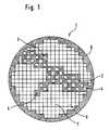
- Zones 2 , 3 , 4 and 5can be seen schematically in FIG. 1, which zones are intended to represent channels 6, which correspond to the target geometry of an idealized honeycomb body monolith in predetermined tolerances. Said zones are square in the embodiment shown. The light-colored fields within the zones indicate those channels which are left open when the method is carried out, whereas the blackened areas lie on those channels 6 which are to be closed. The blackened points are then also the positions at which an assigned dosing head has the nozzles, by means of which the stopper mass enters the relevant channels is injected. Zone 2 spans a total of 16 channels, 8 of which are to be closed. The corresponding ratio in zone 3 is 9: 4, in zone 4 4: 2. Zone 5 represents only a single channel 6. In this case, the channel in question must be closed by a dosing head with only one nozzle, since the geometric deviations are so great that no other dosing head with several nozzles can be used.
- an end face of the monolith 1is now scanned and the image information is stored in a memory of a computer.
- the centers of the channelsare then determined under program control.
- the computer softwarenow virtually places the grids of zones 2 to 5 over the stored image information, with the aim of optimizing to be able to use the largest zone 2 as often as possible. If this does not succeed, smaller zones are placed over the image information in the memory of the computer until all channels are finally divided into zone areas by software. From this, the computer then calculates a processing path that determines which dosing heads in which order the monolith 1 should be approached.
- the monolith 1is thus firstly brought up to the dosing head with the largest number of nozzles, which are arranged in the same pattern as zone 2 .
- the monolithis moved accordingly and moved to the largest dosing head again or several times at different points.
- the next smaller determined zones of the monolithare displayed move on to the next smaller dosing head until channels can remain that require special treatment by a dosing head with only one nozzle.
- the channels 6 of the monolith 1are closed on one of its end faces.
- the monolithis then rotated through 180 ° and moved accordingly, although a complementary closure pattern for the channels is maintained.
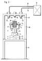
- the device for carrying out the methodis shown schematically in FIG. 2.
- a base frame 15carries a motor-driven carriage device 12, 13 and 21, between which a rotating device 14 is also connected.
- the slide deviceallows the movement in all three spatial axes of a bracket 27 carried by it, to which a tensioning and turning device 11 is attached.
- This clamping and turning device 11clamps a honeycomb monolith 1 between its jaws, the two end faces 19 and 20 of which are to be machined in the manner already described.
- the slide device 12, 13 and 21 as well as the rotating device 14 and the tensioning and turning device 11are controlled by a computer (not shown) in accordance with the processing path defined by the computer.
- the base frame 15also supports a frame 26 which overlaps the slide device and the tensioning and turning device.
- a camera 10is permanently embedded in the frame 26 as an image sensor.
- the main axis of the camera 10is aligned with the main axis of the monolith 1.
- two dosing heads 17 and 18are shown in FIG. 2, which are likewise firmly embedded in the frame 26. These are connected via lines 24 and 25 to a metering system 16 and are computer-controlled fed with the viscous stopper mass contained in the metering system 16.
- the dosing headshave different numbers of nozzles 22 and 23. According to the result of the image processing, the dosing heads 22 and 23 are approached by the slide device and the monolith 1 is moved by the component 21 to the respective dosing head, which then injects the stopper mass into the defined channels 6 in the monolith 1.
Landscapes
- Chemical & Material Sciences (AREA)
- Engineering & Computer Science (AREA)
- Ceramic Engineering (AREA)
- Chemical Kinetics & Catalysis (AREA)
- Geometry (AREA)
- Structural Engineering (AREA)
- Physics & Mathematics (AREA)
- Mechanical Engineering (AREA)
- Materials Engineering (AREA)
- Organic Chemistry (AREA)
- Filtering Materials (AREA)
- Exhaust Gas After Treatment (AREA)
- Processes For Solid Components From Exhaust (AREA)
- Filtering Of Dispersed Particles In Gases (AREA)
Description
Translated fromGermanDie Erfindung betrifft ein Verfahren und eine Vorrichtung zur Herstellung eines Filters in Form eines keramischen Wabenkörper-Monolithen, und zwar ausgehend von einem Rohling des Wabenkörper-Monolithen.The invention relates to a method and a device for producing a filter in the form of a ceramic honeycomb monolith, starting from a blank of the honeycomb monolith.
Derartige Filter finden beispielsweise als Dieselrußfilter im Zuge der öffentlichen Umweltdiskussion zunehmend Einsatz in PKWs, LKWs und Bussen, die mit einem Dieselmotor angetrieben werden.Such filters are increasingly used, for example, as diesel soot filters in the course of the public environmental discussion in cars, trucks and buses which are driven by a diesel engine.
Die Wirkung eines derartigen Filters beruht darauf, daß die Kanäle des wabenförmigen Monolithen wechselseitig an beiden Seiten derartig verschlossen werden, daß das Abgas gezwungen wird, durch die porösen Wände zwischen den Kanälen hindurchzuströmen. Dabei dienen die Wände als eigentliche Filter für den in Partikel auftretenden Ruß oder - je nach Einsatzfall - auszufilternden Stoff. Freilich werden sich die Kanäle nach einiger Zeit mit Ruß o. dgl. zusetzen, weswegen ein solcher Filter von Zeit zur Zeit regeneriert werden muß, d.h. in der Regel erhitzt werden muß, damit die zurückgehaltenen Partikel oxidiert werden.The effect of such a filter is based on the fact that the channels of the honeycomb monolith are mutually closed on both sides in such a way that the exhaust gas is forced to flow through the porous walls between the channels. The walls serve as actual filters for the soot occurring in particles or - depending on the application - the material to be filtered out. Of course, the channels will clog with soot or the like after some time, which is why such a filter has to be regenerated from time to time, i.e. usually must be heated so that the retained particles are oxidized.
Die Rohlinge für die Wabenkörper bestehen häufig aus Sinterglaskeramik-Monolithen, die meist durch ein Extrudierverfahren mit anschließender Trocknung und Sinterung zur Verfügung gestellt werden. Durch das Trocknen und durch das Sintern schrumpft der Körper, und dies unter ungleichmäßiger Schrumpfung. Diese ungleichmäßige Schrumpfung resultiert in einer nicht kalkulierbaren Abweichung der Ist-Geometrie von der Soll-Geometrie eines idealisierten Wabenkörpers. Zusätzlich führt der Extrudiervorgang zu einem Verzug der Wabenstruktur.The blanks for the honeycomb bodies often consist of sintered glass ceramic monoliths, which are usually made available by an extrusion process with subsequent drying and sintering. The body shrinks due to drying and sintering, and this with uneven shrinkage. This non-uniform shrinkage results in an incalculable deviation of the actual geometry from the target geometry of an idealized honeycomb body. In addition, the extrusion process leads to a distortion of the honeycomb structure.
Die besagten Abweichungen haben nun erheblichen Einfluß auf die weitere Verarbeitung des Wabenkörper-Monolithen, wenn es nämlich darum geht, die Kanäle auf beiden Stirnseiten wechselseitig zu verschließen.The said deviations now have a considerable influence on the further processing of the honeycomb monolith, namely when it is a question of mutually closing the channels on both end faces.
Die ganze Tragweite des damit verbundenen Problems einer großtechnischen Herstellung wird deutlich anhand eines Standard-Monolithen mit einem Durchmesser von 5,66'' (14,4 cm). Das Wabenrohmaß beträgt ca. 3,6 x 3,6 mm, so daß ca. 1.400 Wabenkanäle pro Stirnseite mit einem Lochquerschnitt von jeweils 2,4 x 2,4 mm vorhanden sind. Auf jeder Stirnseite müssen daher wechselseitig etwa 700 Wabenöffnungen und damit Filterkanäle verschlossen werden. Aufgrund der erwähnten Abweichungen von der Sollgeometrie des Monolithen ist es nicht möglich, in diesem Falle die 700 Öffnungen pro Stirnseite mit einem Düsenkopf mit 700 Düsen auf einmal in einem Arbeitsgang zu verschließen. Auch das Verschließen jeden zweiten Kanals mittels der sogenannten Stöpselmasse per Hand ist nicht vertretbar im Hinblick auf die dabei entstehenden hohen Personalkosten.The full scope of the problem associated with large-scale manufacturing is illustrated by a standard monolith with a diameter of 5.66 '' (14.4 cm). The raw honeycomb size is approx. 3.6 x 3.6 mm, so that there are approx. 1,400 honeycomb channels per end face with a hole cross section of 2.4 x 2.4 mm each. Around 700 honeycomb openings and thus filter channels must therefore be closed on each end. Due to the mentioned deviations from the nominal geometry of the monolith, it is not possible in this case to close the 700 openings per end face with a nozzle head with 700 nozzles at once in one operation. The closing of every second channel by means of the so-called stopper mass by hand is also not justifiable in view of the high personnel costs involved.
Im Stand der Technik sind bereits Vorrichtungen und Verfahren zum wechselseitigen Verschließen der Wabenkanäle eines Wabenkörper-Monolithen vorgeschlagen worden. Beispielhaft wird auf die sehr anschauliche US-A-4 411 856 verwiesen. Darin wird vorgeschlagen, eine eine Stirnseite des Monolithen vollständig bedeckende Maske zu verwenden, die mit Durchgängen und mit zapfenförmigen Ansätzen auf der dem Monolithen zugewandten Seite versehen ist. Die Zapfen werden in die nicht zu verschließenden Kanäle gesetzt, wohingegen die Stöpselmasse durch die Durchgänge in der Maske in die Endbereiche der zu verschließenden Kanäle gebracht wird. Der bereits oben erwähnten Abweichung des Monolithen von einer idealisierten Sollgeometrie wird dadurch versucht Rechnung zu tragen, daß die verwendete Maske aus einem elastischen Material besteht. In engen Grenzen mag diese Methode anwendbar sein. Problematisch allerdings ist, daß der Abstand der erwähnten Zapfen zu den Durchgängen festgelegt ist, so daß der durch die Elastizität der Maske erzielte Ausgleich der Abweichungen des Monolithen von der Sollgeometrie auf relativ geringe Werte beschränkt bleibt.Devices and methods for mutually closing the honeycomb channels of a honeycomb monolith have already been proposed in the prior art. Reference is made, for example, to the very illustrative US Pat. No. 4,411,856. It is proposed to use a mask that completely covers an end face of the monolith, which mask is provided with passages and with cone-shaped projections on the side facing the monolith. The pins are placed in the channels that are not to be closed, whereas the stopper mass is brought through the passages in the mask into the end regions of the channels to be closed. The already mentioned deviation of the monolith from one Idealized target geometry is attempted to take account of the fact that the mask used consists of an elastic material. This method may be applicable within narrow limits. It is problematic, however, that the distance between the pins mentioned and the passages is fixed, so that the compensation of the deviations of the monolith from the nominal geometry achieved by the elasticity of the mask remains limited to relatively small values.
Ein weiteres Verfahren ist bekannt geworden aus der US-A-4,557,773. Darin wird vorgeschlagen, die Stirnseite eines Monolithen zunächst mit einer Folie komplett abzudecken und danach mittels eines speziellen Werkzeuges diejenigen Kanäle wieder zu öffnen, in welche Stöpselmasse eingebracht werden soll. Es handelt sich hierbei also ebenso wie die vorerwähnten Verfahren um ein indirektes Verfahren, bei dem die nicht zu verschließenden Kanäle abgedeckt werden.Another method has become known from US-A-4,557,773. It is proposed to first completely cover the front face of a monolith with a film and then to open those channels into which plug material is to be introduced using a special tool. Like the aforementioned methods, this is an indirect method in which the channels that cannot be closed are covered.
Schließlich sei auf das in der US-A-4,329,162 umrissene Verfahren hingewiesen, von welchem im übrigen im Oberbegriff des Anspruchs 1 ausgegangen wird. In der besagten Druckschrift wird erwähnt, daß eine Dosiervorrichtung mit (mehreren) Düsen direkt in die Kanäle eingefahren wird und durch die Düsen dann die Stöpselmasse in die jeweilig zu verschließenden Kanäle eingebracht wird. Zwar ist dieser Druckschrift zu entnehmen, daß ohne die weiter oben beschriebenen Verfahrensschritte zur Abdeckung der nicht zu verschließenden Kanäle gearbeitet wird. Gleichwohl wird sich dieses Verfahren nicht für eine großtechnische Anwendung eignen. Entweder weist der Düsenkopf sehr viele Düsen auf, daß das Verfahren an die Grenzen der Toleranzweiten bei der Herstellung des Wabenkörper-Rohlings stößt, oder aber die Dosiervorrichtung verfügt nur über sehr wenige Düsen, so daß das Verfahren unwirtschaftlich arbeitet dadurch, daß diese Dosiervorrichtung entsprechend häufig abgesenkt werden muß in die während dieses Arbeitsvorganges jeweilig zu verschließenden Kanäle.Finally, reference is made to the method outlined in US Pat. No. 4,329,162, which is also assumed in the preamble of claim 1. In the said publication it is mentioned that a dosing device with (several) nozzles is inserted directly into the channels and the plug material is then introduced through the nozzles into the respective channels to be closed. It can be seen from this publication that work is carried out without the process steps described above for covering the channels which cannot be closed. Nonetheless, this process will not be suitable for large-scale use own. Either the nozzle head has a large number of nozzles that the method reaches the limits of the tolerance ranges in the production of the honeycomb blank, or the metering device has very few nozzles, so that the method is uneconomical in that this metering device is correspondingly frequent must be lowered into the channels to be closed during this operation.
Es ist die Aufgabe der vorliegenden Erfindung vor dem dargelegten Hintergrund, ein Verfahren zur Herstellung eines Filters in Form eines keramischen Wabenkörper-Monolithen zu schaffen, bei dem ausgehend von einem Rohling des Monolithen die Kanäle an den Stirnseiten wechselseitig im großtechnischen Maßstab mit einer Stöpselmasse verschlossen werden. Darüber hinaus soll eine Vorrichtung zur Durchführung des Verfahrens geschaffen werden.It is the object of the present invention against the background set out to provide a method for producing a filter in the form of a ceramic honeycomb monolith, in which, starting from a blank of the monolith, the channels on the end faces are mutually closed on an industrial scale with a stopper mass . In addition, an apparatus for performing the method is to be created.
Gelöst wird diese Aufgabe durch das Verfahren gemäß dem Anspruch 1 und durch die Vorrichtung gemäß Anspruch 4. Vorteilhafte Weiterbildungen ergeben sich aus den Unteransprüchen.This object is achieved by the method according to claim 1 and by the device according to claim 4. Advantageous further developments result from the subclaims.
Verfahrensmäßig wird vorgeschlagen, Zonen von Kanälen auf beiden Stirnseiten zu ermitteln, die in vorgebbaren Toleranzen der Sollgeometrie eines idealisierten Wabenkörpers entsprechen, wobei die Zonen eine möglichst hohe Anzahl von Kanälen beinhalten soll. Die Zonen korrespondieren mit Dosierköpfen einer Dosiervorrichtung. Die Dosierköpfe mit unterschiedlichen Anzahlen von Düsen, die in die zu verschließenden Kanäle abgesenkt werden, um die zähflüssige Stöpselmasse in deren Endbereich einzubringen, werden motorisch so verfahren und angesteuert, daß entsprechend der genannten Ermittlung der Zonen von Kanälen der Dosierkopf mit der höchsten Anzahl von Düsen am häufigsten zum Einsatz kommt. Sind alle diese Zonen abgearbeitet, wird der Dosierkopf mit der nächstniedrigeren Anzahl von Düsen verwendet. Dies wird solange fortgeführt, bis alle vorgesehenen Kanäle verschlossen sind, was auch bedeuten kann, daß einzelne Kanäle mit einem Dosierkopf mit lediglich einer einzelnen Düse angesteuert werden. Der so vorbereitete Wabenkörper-Monolith wird anschließend einem Keramisierungsprozeß unterworfen, bei dem der Wabenkörper nochmals schrumpft. Bei geeigneter Materialwahl für die Stöpselmasse wird diese weniger schrumpfen als das Material des Wabenkörpers, so daß eine fester Sitz des Stöpsels in den Endbereichen der Kanäle gewährleistet ist.In terms of the method, it is proposed to determine zones of channels on both end faces which correspond to the target geometry of an idealized honeycomb body in predeterminable tolerances, the zones being intended to contain the largest possible number of channels. The zones correspond to dosing heads of a dosing device. The dosing heads with different numbers of nozzles, which are lowered into the channels to be closed in order to introduce the viscous stopper mass into their end area, become motorized method and controlled that the dosing head with the highest number of nozzles is used most frequently according to the above-mentioned determination of the zones of channels. When all these zones have been processed, the dosing head with the next lower number of nozzles is used. This is continued until all the channels provided are closed, which can also mean that individual channels are controlled with a dosing head with only a single nozzle. The honeycomb body monolith prepared in this way is then subjected to a ceramization process in which the honeycomb body shrinks again. With a suitable choice of material for the stopper mass, this will shrink less than the material of the honeycomb body, so that a firm fit of the stopper is ensured in the end regions of the channels.
In bevorzugter Weise wird zunächst die erste Stirnseite von einem Bildaufnehmer, beispielsweise einer Fernsehkamera, abgetastet und das abgetastete Bild in einem Speicher eines Rechners abgelegt.In a preferred manner, the first end face is first scanned by an image recorder, for example a television camera, and the scanned image is stored in a memory of a computer.
Der Rechner sucht das Bild nach zusammenhängenden Zonen von Kanälen ab, die in vorgebbaren Toleranzen der Sollgeometrie entsprechender Zonen eines idealisierten Wabenkörper-Monolithen entsprechen. Dieses Aufsuchen von zusammenhängenden Zonen erfolgt programmgesteuert. Sodann wird die Abarbeitungsbahn der durch den Rechner angesteuerten Dosierköpfe festgelegt. Dies geschieht in Übereinstimmung mit der Erfindung nach der Maßgabe, daß möglichst der Dosierkopf mit den meisten Düsen am häufigsten zum Einsatz kommt. Hierdurch wird- wie leicht einzusehen ist - die Zeit für das Verschließen der Kanäle optimiert, d.h. minimiert, indem nämlich möglichst viele Kanäle simultan verschlossen werden. In den Restzonen, beispielsweise am Rande des Monolithen, werden Zonen mit nur noch wenigen zu verschließenden Kanälen übrig bleiben, für die dann ein Dosierkopf mit weniger, beispielsweise zwei oder vier Düsen, zum Einsatz kommt.The computer searches the image for contiguous zones of channels which, in predefinable tolerances, correspond to the target geometry of corresponding zones of an idealized honeycomb monolith. This search for contiguous zones is program-controlled. Then the processing path of the dosing heads controlled by the computer is determined. This is done in accordance with the invention, provided that the dosing head with the most nozzles is used most frequently. As is easy to see, this optimizes the time for closing the channels, ie minimizes them, because as many channels as possible are closed simultaneously. In the remaining zones, for example on the edge of the monolith, there will be zones with only a few channels left to be closed, for which a dosing head with fewer, e.g. two or four nozzles, will be used.
Entsprechend der festgelegten Abarbeitungsbahn werden die Düsen der jeweiligen Dosierköpfe in die zu verschließenden Kanäle abgesenkt und die zähflüssige Stöpselmasse wird in die Endbereiche der Kanäle eingebracht, woraufhin die Düsen wieder aus den Kanälen herausbewegt werden.According to the defined processing path, the nozzles of the respective dosing heads are lowered into the channels to be closed and the viscous stopper mass is introduced into the end regions of the channels, whereupon the nozzles are moved out of the channels again.
Nachdem die eine Stirnseite des Monolithen so behandelt worden ist und entsprechend alle vorgesehenen Kanäle mit der Stöpselmasse verschlossen worden sind, wird der Monolith um 180° Grad gedreht. Die Kanäle werden auf der anderen Stirnseite in entsprechender Weise verschlossen, allerdings in einem komplementären Muster wie zu jenem auf der ersten Stirnseite. Erst hierdurch wird ja der Monolith überhaupt zum Filter.After the one face of the monolith has been treated in this way and all the channels provided have been closed with the stopper mass, the monolith is rotated through 180 °. The channels are closed in a corresponding manner on the other end face, but in a complementary pattern to that on the first end face. Only then does the monolith become a filter at all.
Vorteilhaft bilden die Umrisse der ermittelten Zonen von Kanälen ein Rechteck. Diese Verfahrensweise korrespondiert mit einer gegenständlichen Ausbildung der Dosierköpfe, bei denen die Düsen in einer rechteckigen Matrix angeordnet sind.The contours of the determined zones of channels advantageously form a rectangle. This procedure corresponds to a physical design of the dosing heads, in which the nozzles are arranged in a rectangular matrix.
Die erfindungsgemäße Vorrichtung zur Durchführung des Verfahrens weist die folgenden Komponenten auf:
- a) Eine in den drei räumlichen Achsen verfahrbare mechanische Verfahreinheit, wie eine Schlitteneinrichtung, die eine um ihre Hochachse durch eine Drehvorrichtung motorisch verschwenkbare Spann- und Wendeeinrichtung aufweist. In die letztere ist der Wabenkörper-Monolith um die Horizontalachse verschwenkbar einspannbar.
- b) Einen über der einen Stirnseite des in der Spann- und Wendeeinrichtung eingespannten Monolithen angeordneten Bildaufnehmer, wie beispielsweise eine Fernsehkamera, der die Stirnseite des Monolithen abtastet und die Bildinformationen an einen Rechner leitet, der sie in seinem Speicher ablegt.
- c) Mindestens zwei Dosierköpfe mit jeweils unterschiedlicher Anzahl von Düsen, die über Leitungen mit einer Dosieranlage für die zähflüssige Stöpselmasse verbunden sind und an die der Monolith durch Ansteuerung der Schlitteneinrichtung sowie der Spann- und Wendeeinrichtung herangefahren werden kann gemäß der vorher erfolgten Festlegung der Abarbeitungsbahn durch den Rechner zum Einbringen der Stöpselmasse in die Endbereiche der Kanäle des Monolithen.
- a) A mechanical travel unit which can be moved in the three spatial axes, such as a slide device which has a tensioning and turning device which can be pivoted about its vertical axis by a rotating device. In the latter is the Honeycomb body monolith can be clamped pivotable about the horizontal axis.
- b) An image sensor arranged above the one end face of the monolith clamped in the tensioning and turning device, such as a television camera, which scans the end face of the monolith and forwards the image information to a computer which stores it in its memory.
- c) At least two dosing heads, each with a different number of nozzles, which are connected via lines to a dosing system for the viscous stopper mass and to which the monolith can be approached by actuating the slide device and the tensioning and turning device in accordance with the previously defined processing path the computer for introducing the plug mass into the end regions of the channels of the monolith.
Bevorzugt sind die Dosierköpfe und der Bildaufnehmer in einem Rahmen starr gelagert, und zwar überhalb des in der Spann- und Wendeeinrichtung gehaltenen Monolithen, wobei die eine zu bearbeitende Stirnseite des Monolithen dem Bildaufnehmer und den Dosierköpfen zugewandt ist. Rechnergesteuert wird dann der Monolith über die Schlitteneinrichtung entsprechend der festgelegten Abarbeitungsbahn an den jeweiligen Dosierkopf herangefahren, woraufhin dessen Düsen in die während eines Arbeitstaktes jeweilig zu verschließenden Kanäle im Monolithen eingeführt werden, wozu die Schlitteneinrichtung eine entsprechende Hubbewegung ausführt. Nach Erreichen dieser Position des Monolithen veranlaßt der Rechner die Dosieranlage, daß Stöpselmasse über die entsprechenden Leitungen in die betreffenden Düsen gedrückt wird und in die Endbereiche der betreffenden Kanäle eingespritzt wird. Vorzugsweise wird der Monolith während des Einspritzvorganges entsprechend der Einspritzgeschwindigkeit und der Einspritzmenge nach unten weggeführt, so daß der Verschluß der Kanäle durch die Stöpselmasse bündig mit der Stirnseite des Monolithen abschließt. Ist vom Rechner eine weitere Zone auf der Stirnseite ermittelt worden, die an denselben Dosierkopf geführt werden kann, so verfährt die Schlitteneinrichtung den Monolithen um die entsprechende Strecke, woraufhin der Vorgang wiederholt wird. Ist keine weitere Zone ermittelt worden, die mit demselben Dosierkopf bearbeitet werden kann aufgrund größerer Abweichungen von der Sollgeometrie eines idealisierten Wabenkörper-Monolithen, so wird die Schlitteneinrichtung den eingespannten Monolithen zu einem anderen ausgewählten Dosierkopf mit weniger Düsen verfahren, an dem der Verschlußvorgang in entsprechender Weise durchgeführt wird.The dosing heads and the image sensor are preferably rigidly mounted in a frame, specifically above the monolith held in the clamping and turning device, the one end face of the monolith to be processed facing the image sensor and the dosing heads. Computer-controlled, the monolith is then moved to the respective dosing head via the slide device in accordance with the defined processing path, whereupon its nozzles are introduced into the channels in the monolith to be closed during a work cycle, for which purpose the slide device executes a corresponding lifting movement. After reaching this position of the monolith, the computer prompts the dosing system that the stopper mass is over the corresponding lines are pressed into the relevant nozzles and injected into the end regions of the relevant channels. The monolith is preferably guided downward during the injection process in accordance with the injection speed and the injection quantity, so that the closure of the channels by the stopper mass is flush with the end face of the monolith. If the computer has determined a further zone on the end face that can be guided to the same dosing head, the slide device moves the monolith by the appropriate distance, whereupon the process is repeated. If no other zone has been determined that can be processed with the same dosing head due to larger deviations from the target geometry of an idealized honeycomb body monolith, the slide device will move the clamped monolith to another selected dosing head with fewer nozzles, on which the sealing process is carried out in a corresponding manner is carried out.
Nach dem Verschluß aller auf der ersten Stirnseite in Frage kommenden Kanäle wird die Spann- und Wendeeinrichtung den Monolithen um 180° Grad drehen. Die Vorrichtung verfährt dann mit der zweiten Stirnseite in entsprechender Weise wie mit der ersten Stirnseite, wobei allerdings das Verschlußmuster komplementär ist zu jenem auf der ersten Stirnseite, so daß sich die Filterkanäle ausbilden. Die Erzeugung des komplementären Verschlußmusters auf der zweiten Stirnseite des Monolithen bereitet keine Schwierigkeiten, da das Verschlußmuster der ersten Stirnseite im Speicher des Rechners abgelegt ist. Die Erzeugung des komplementären Musters ist daher eine von der Software des Rechners einfach zu bewerkstellende Aufgabe.After all the channels on the first end face have been closed, the tensioning and turning device will rotate the monolith by 180 °. The device then moves with the second end face in the same way as with the first end face, although the closure pattern is complementary to that on the first end face, so that the filter channels are formed. The generation of the complementary closure pattern on the second end face of the monolith presents no difficulties since the closure pattern of the first end face is stored in the memory of the computer. The generation of the complementary pattern is therefore one of the Computer software task easy to do.
Vorzugsweise sind die Düsen der Dosierköpfe in einer rechteckigen Gesamtanordnung jeweils diagonal gegenüberliegend angeordnet. Dieser Ausbildung korrespondiert mit dem bevorzugten Verfahrensmerkmal, wonach die Umrisse der ermittelten Zonen von Kanälen ein Rechteck bilden.The nozzles of the dosing heads are preferably arranged diagonally opposite one another in a rectangular overall arrangement. This design corresponds to the preferred method feature, according to which the outlines of the determined zones of channels form a rectangle.
Das erfindungsgemäße Verfahren sowie die Vorrichtung erfüllen die Anforderungen einer Massenproduktion in vorbildlicher Weise. So können die Kanäle eines Referenz-Monolithen mit den eingangs erwähnten Abmessungen und der erwähnten Anzahl von Kanälen innerhalb etwa 15 Minuten wechselseitig verschlossen werden.The inventive method and the device meet the requirements of mass production in an exemplary manner. The channels of a reference monolith with the dimensions and the number of channels mentioned can be mutually closed within approximately 15 minutes.
Der so vorbereitete Monolith wird dann einem an sich bekannten Keramisierungsprozeß unterworfen.The monolith prepared in this way is then subjected to a known ceramization process.
Die Erfindung wird kurz anhand der Zeichnungsfiguren näher erläutert.The invention is briefly explained with reference to the drawing figures.
Es zeigt:
- Figur 1
- eine schematische Aufsicht auf eine Stirnseite eines Wabenkörper-Monolithen mit schematisiert dargestellten Zonen von Kanälen unterschiedlicher Größe,
Figur 2- eine Prinzipdarstellung der erfindungsgemäßen Vorrichtung.
- Figure 1
- 1 shows a schematic plan view of an end face of a honeycomb monolith with schematically represented zones of channels of different sizes,
- Figure 2
- a schematic diagram of the device according to the invention.
Nachfolgend bezeichnen dieselben Bezugszeichen gleiche Teile.In the following, the same reference symbols designate the same parts.
Der Wabenkörper-Monolith 1 weist eine Vielzahl von Kanälen 6 auf, die voneinander durch die Kanalwände 7 getrennt sind. Diese Kanalwände 7 sind porös und üben nach dem wechselweisen Verschluß der Kanäle 6 auf beiden Stirnseiten des Monolithen 1 die eigentliche Filterfunktion aus, indem nämlich Partikel von den Wänden 7 zurückgehalten werden, wohingegen Abgase durch die Wände hindurch in die benachbarten Kanäle treten können, die auf der anderen Stirnseite unverschlossen sind und aus denen daher die Abgase austreten können. Die Außenwandung 8 des Monolithen ist im übrigen abgasundurchlässig.The honeycomb monolith 1 has a plurality of
Die Geometrie des in Figur 1 dargestellten Monolithen ist idealisiert. In der Realität treten nicht unerhebliche Abweichungen von dieser Sollgeometrie in Folge unterschiedlicher Schrumpfung beim Trocknen und Sintern des Monolithen sowie in Folge des Verzugs der Wabenstruktur beim Extrudieren auf.The geometry of the monolith shown in Figure 1 is idealized. In reality, significant deviations from this nominal geometry occur as a result of different shrinkage during drying and sintering of the monolith and as a result of the warping of the honeycomb structure during extrusion.
In Figur 1 erkennbar sind schematisiert dargestellt Zonen2,3,4 und5, welche Zonen von Kanälen 6 repräsentieren sollen, die in vorgebbaren Toleranzen der Sollgeometrie eines idealisierten Wabenkörper-Monolithen entsprechen. Die besagten Zonen sind im dargestellten Ausführungsbeispiel quadratisch ausgebildet. Die hellbelassenen Felder innerhalb der Zonen weisen auf diejenigen Kanäle hin, die bei der Durchführung des Verfahrens offengelassen werden, wohingegen die geschwärzten Stellen auf denjenigen Kanälen 6 liegen, welche zu verschließen sind. Die geschwärzten Stellen sind dann ebenfalls die Positionen, an denen ein zugeordneter Dosierkopf die Düsen aufweist, mittels derer die Stöpselmasse in die betreffenden Kanäle eingespritzt wird. So übergreift die Zone2 insgesamt 16 Kanäle von denen 8 verschlossen werden sollen. Das entsprechende Verhältnis in der Zone3 beträgt 9:4, bei der Zone4 4:2. Die Zone5 repräsentiert lediglich einen einzelnen Kanal 6. In diesem Falle muß der betreffende Kanal durch einen Dosierkopf mit nur einer Düse verschlossen werden, da die geometrischen Abweichungen so groß sind, daß kein anderer Dosierkopf mit mehreren Düsen verwendet werden kann.
Gemäß dem erfindungsgemäßen Verfahren wird nun eine Stirnseite des Monolithen 1 abgetastet und die Bildinformation in einem Speicher eines Rechners abgelegt. Sodann werden programmgesteuert die Zentren der Kanäle ermittelt. Die Software des Rechners legt nun quasi die Raster der Zonen2 bis5 über die abgespeicherte Bildinformation, wobei im Sinne einer Optimierung versucht wird, die größte Zone2 möglichst häufig anwenden zu können. Gelingt dies nicht, werden kleinere Zonen über die Bildinformation im Speicher des Rechners gelegt, so lange, bis schließlich alle Kanäle softwaremäßig in Zonenbereiche eingeteilt sind. Hieraus errechnet der Rechner sodann eine Abarbeitungsbahn, die festlegt, an welche Dosierköpfe in welcher Reihenfolge der Monolith 1 herangefahren werden soll. Beginnend mit der größten Zone2 wird der Monolith 1 also beispielsweise zunächst an den Dosierkopf mit der größten Anzahl von Düsen, die im selben Muster wie die Zone2 angeordnet sind, herangeführt. In dem erhofften Falle, daß noch mehrere Zonen dieser Größe ermittelt worden sind, wird der Monolith entsprechend verfahren und nochmals oder mehrmalig an verschiedenen Stellen an den größten Dosierkopf herangefahren. Danach werden beispielsweise die nächst kleineren ermittelten Zonen des Monolithen an den nächst kleineren Dosierkopf herangefahren, bis schließlich Kanäle übrig bleiben können, die eine gesonderte Behandlung durch einen Dosierkopf mit nur einer Düse erforderlich machen.In accordance with the method according to the invention, an end face of the monolith 1 is now scanned and the image information is stored in a memory of a computer. The centers of the channels are then determined under program control. The computer software now virtually places the grids of
Nach der Durchführung dieses Verfahrens sind die Kanäle 6 des Monolithen 1 auf einer seiner Stirnflächen verschlossen. Der Monolith wird sodann um 180° Grad gedreht und entsprechend verfahren, wobei allerdings ein komplementäres Verschlußmuster für die Kanäle eingehalten wird.After carrying out this method, the
Nach dem gezielten Verschließen der Kanäle 6 auf beiden Stirnseiten des Monolithen 1 wird dieser einem üblichen Keramisierungsprozeß unterworfen, an dessen Ende der fertige Filter steht.After the
Die Vorrichtung zur Durchführung des Verfahrens ist schematisiert in Figur 2 dargestellt.The device for carrying out the method is shown schematically in FIG. 2.
Ein Grundrahmen 15 trägt eine motorisch-verfahrbare Schlitteneinrichtung 12,13 und 21, zwischen denen noch eine Drehvorrichtung 14 geschaltet ist. Die Schlitteneinrichtung gestattet das Verfahren in allen drei Raumachsen eines von ihr getragenen Bügels 27, an der eine Spann- und Wendeeinrichtung 11 angebracht ist. Diese Spann- und Wendeeinrichtung 11 spannt zwischen ihren Backen einen Wabenkörper-Monolithen 1 ein, dessen beide Stirnseiten 19 und 20 in der bereits beschriebenen Weise bearbeitet werden sollen. Die Schlitteneinrichtung 12,13 und 21 sowie die Drehvorrichtung 14 und die Spann- und Wendeeinrichtung 11 werden von einem (nicht dargestellten) Rechner angesteuert in Übereinstimmung mit der vom Rechner festgelegten Abarbeitungsbahn.A
Das Grundgestell 15 stützt darüberhinaus ein die Schlitteneinrichtung sowie die Spann- und Wendeeinrichtung übergreifenden Rahmen 26. Oberhalb des Monolithen 1 ist eine Kamera 10 als Bildaufnehmer fest in dem Rahmen 26 eingelassen. Die Hauptachse der Kamera 10 ist mit der Hauptachse des Monolithen 1 ausgerichtet. Darüberhinaus sind in der Figur 2 dargestellt zwei Dosierköpfe 17 und 18, die ebenfalls fest in dem Rahmen 26 eingelassen sind. Diese sind über Leitungen 24 und 25 mit einer Dosieranlage 16 verbunden und werden rechnergesteuert mit der in der Dosieranlage 16 enthaltenen zähflüssigen Stöpselmasse gespeist.The
Die Dosierköpfe weisen unterschiedliche Anzahlen von Düsen 22 und 23 auf. Entsprechend dem Ergebnis der Bildverarbeitung werden die Dosierköpfe 22 und 23 von den Schlitteneinrichtung angefahren und der Monolith 1 durch die Komponente 21 an den jeweiligen Dosierkopf herangefahren, der dann in die festgelegten Kanäle 6 im Monolithen 1 die Stöpselmasse einspritzt.The dosing heads have different numbers of
Claims (6)
- Process for producing a filter in the form of a ceramic honeycomb monolith (1) having a plurality of through channels (6), which at the end faces (19, 20) of the monolith (1) are closed at alternate ends by a plug, starting with a moulded blank of the honeycomb monolith made of ceramizable material and having channels (6) open at both ends, the plug substance being introduced into the channels which are to be closed directly by a nozzle-holding dosing head of a dosing apparatus,
characterized in that- zones (2, 3, 4, 5) of channels (6) at both end faces (19, 20) are determined which within preselectable tolerances correspond to the setpoint geometry of an ideal honeycomb monolith, with the proviso that the zones contain the highest possible number of channels (6),- dosing heads (17, 18) of the dosing apparatus, having differing numbers of nozzles which are lowered into the channels (6) to be closed in order to introduce the viscous plug substance into their end region, are motor-driven and -controlled in such a manner that, in accordance with said determination of the zones of channels (6), the dosing head (17) with the highest number of nozzles (22) is used most frequently and then the dosing head with the second highest number of nozzles is used and so on until all of the provided channels (6) are closed, and the honeycomb monolith (1) thus prepared is then subjected to a ceramization process. - Process according to claim 1, in which- first the first end face (19) is scanned by a camera (10) and the scanned image is filed in a memory of a computer,- the computer sweeps the image for coherent zones (2, 3, 4, 5) of channels (6) which within preselectable tolerances correspond to the setpoint geometry of a corresponding zone of an ideal honeycomb monolith,- the processing path of the dosing heads (17, 18) controlled by the computer is defined,- in accordance with the defined processing path, the nozzles (22, 23) of the respective dosing heads (17, 18) are lowered into the channels to be closed, the plug substance is introduced into the end regions of the channels and then the nozzles (22, 23) are removed from said channels,- the monolith (1), after plugging of the channels at the first end face (19), is rotated through 180° and in a corresponding manner the channels at the other end face (20) are closed in a pattern complementary to that at the first end face (19).
- Process according to claim 1 or 2, in which the contours of the determined zones form a rectangle.
- Apparatus for effecting the process according to one of claims 1 to 3, having- a slide device (12, 13, 21), which may be motor-driven in the three spatial axes (x, y, z) and has a clamping and turning device (11), which may be swivelled in a powered manner about its vertical axis by a slewing mechanism (14) and in which the honeycomb monolith (1) is clampable so as to be capable of swivelling about the horizontal axis (x),- a camera (10) which is disposed above the one end face (19) of the monolith (1) clamped in the clamping and turning device (11), scans the end face (19) and passes the image data to a memory of a computer,- at least two dosing heads (17, 18), each having a different number of nozzles (22, 23), which are connected by lines (24, 25) to a dosing installation (16) for the viscous plug substance and towards which the monolith (1) may be moved through control of the slide device (12, 13, 21) and the clamping and turning device (11) in accordance with the definition of the processing path by the computer in order to introduce the plug substance into the end regions of the channels (6) of the monolith (1).
- Apparatus according to claim 4, in which the dosing heads (17, 18) and the camera (10) are disposed, rigidly supported in a frame (26), above the monolith (1) held in the clamping and turning device (11).
- Apparatus according to claim 4 or 5, in which the nozzles of the dosing heads (17, 18) are disposed each diagonally opposite one another in a square overall arrangement.
Applications Claiming Priority (2)
| Application Number | Priority Date | Filing Date | Title |
|---|---|---|---|
| DE4211787 | 1992-04-08 | ||
| DE4211787ADE4211787C1 (en) | 1992-04-08 | 1992-04-08 | METHOD AND DEVICE FOR PRODUCING A FILTER IN THE FORM OF A CERAMIC HONEYCOMB MONOLITH |
Publications (2)
| Publication Number | Publication Date |
|---|---|
| EP0564967A1 EP0564967A1 (en) | 1993-10-13 |
| EP0564967B1true EP0564967B1 (en) | 1995-08-16 |
Family
ID=6456378
Family Applications (1)
| Application Number | Title | Priority Date | Filing Date |
|---|---|---|---|
| EP93105310AExpired - LifetimeEP0564967B1 (en) | 1992-04-08 | 1993-03-31 | Process and apparatus for the production of a filter having the form of a honeycomb |
Country Status (4)
| Country | Link |
|---|---|
| US (2) | US5364573A (en) |
| EP (1) | EP0564967B1 (en) |
| JP (1) | JPH0639219A (en) |
| DE (2) | DE4211787C1 (en) |
Families Citing this family (37)
| Publication number | Priority date | Publication date | Assignee | Title |
|---|---|---|---|---|
| DE4211787C1 (en)* | 1992-04-08 | 1993-11-04 | Schott Glaswerke | METHOD AND DEVICE FOR PRODUCING A FILTER IN THE FORM OF A CERAMIC HONEYCOMB MONOLITH |
| DE4238120C1 (en)* | 1992-11-12 | 1994-03-17 | Schott Glaswerke | Process for the computer-controlled, alternating closing of channels of a honeycomb monolith for exhaust gas purification systems of internal combustion engines |
| EP0677498A3 (en)* | 1994-04-12 | 1996-09-04 | Corning Inc | Method of plugging selected open ends of a ceramic honeycomb structure. |
| DE4424019C1 (en)* | 1994-07-08 | 1996-01-04 | Degussa | Method for closing or filling flow channels on one or both sides in an annular zone of a cylindrical catalyst honeycomb body |
| US5858459A (en)* | 1996-02-22 | 1999-01-12 | Micron Technology, Inc. | Cassette invertor apparatus and method |
| JP3355943B2 (en)* | 1996-07-18 | 2002-12-09 | 松下電器産業株式会社 | Exhaust gas purification method and exhaust gas filter and exhaust gas filter purification device using the same |
| DE19648272A1 (en)* | 1996-11-21 | 1998-05-28 | Emitec Emissionstechnologie | Method and device for determining a cell density of a honeycomb body, in particular for an exhaust gas catalytic converter |
| CN1129619C (en) | 1997-03-17 | 2003-12-03 | 陶氏环球技术公司 | Polyurethane latexes, processes for preparing them and polymers prepared therewith |
| KR20010101807A (en)* | 1999-02-17 | 2001-11-14 | 알프레드 엘. 미첼슨 | Improved method of making multicellular filters |
| NO20001903L (en) | 1999-04-14 | 2000-10-16 | Dow Chemical Co | Polyurethane films made from polyurethane dispersions |
| CN1429239A (en)* | 2000-05-16 | 2003-07-09 | 陶氏环球技术公司 | Polyurethane dispersions and films produced therewith |
| JP4019732B2 (en)* | 2001-03-26 | 2007-12-12 | 株式会社デンソー | Method for plugging ceramic honeycomb molded body |
| DE60239196D1 (en)* | 2001-04-23 | 2011-03-31 | Dow Global Technologies Inc | METHOD FOR PRODUCING A MONOLITHIC WALL FLOW FILTER |
| WO2002085482A2 (en)* | 2001-04-23 | 2002-10-31 | Dow Global Technologies Inc. | Method of making wall-flow monolith filter |
| US6627123B2 (en) | 2002-02-28 | 2003-09-30 | Corning Incorporated | Method for selectively plugging a honeycomb |
| ATE353831T1 (en)* | 2002-07-26 | 2007-03-15 | Jokey Plastik Wipperfuerth | POT-SHAPED VESSEL, ESPECIALLY BUCKET, WITH A LID |
| EP1586431A1 (en)* | 2002-12-05 | 2005-10-19 | Asahi Glass Company Ltd. | Liquid agent injector for ceramics honeycomb and sealing method using it |
| US20060105140A1 (en)* | 2004-11-15 | 2006-05-18 | Andrewlavage Edward F Jr | Mask for plugging particulate filter cells |
| CN101080261B (en)* | 2004-12-22 | 2010-11-03 | 日立金属株式会社 | Method for manufacturing honeycomb filter and honeycomb filter |
| JP4895154B2 (en)* | 2004-12-22 | 2012-03-14 | 日立金属株式会社 | Honeycomb filter manufacturing method and honeycomb filter |
| JP4022893B2 (en)* | 2005-04-28 | 2007-12-19 | 日立金属株式会社 | Honeycomb filter plugging method |
| WO2006127661A2 (en)* | 2005-05-23 | 2006-11-30 | Cornell Research Foundation | Method and system for performing an interfacial reaction in a microfluidic device |
| WO2007004594A1 (en)* | 2005-06-30 | 2007-01-11 | Hitachi Metals, Ltd. | Method of manufacturing ceramic honeycomb filter |
| WO2007097000A1 (en)* | 2006-02-24 | 2007-08-30 | Ibiden Co., Ltd. | End-sealing device for honeycomb formed body, method of placing sealing-material paste, and method of producing honeycomb structure body |
| JP2007038222A (en)* | 2006-08-21 | 2007-02-15 | Hitachi Metals Ltd | Plug stuffing method of honeycomb filter |
| CN101827638B (en) | 2007-08-03 | 2016-07-13 | 埃尔西韦公司 | Porous bodies and methods |
| US8808601B2 (en)* | 2008-05-30 | 2014-08-19 | Corning Incorporated | Method for manufacturing ceramic filter |
| US8277743B1 (en) | 2009-04-08 | 2012-10-02 | Errcive, Inc. | Substrate fabrication |
| US8359829B1 (en) | 2009-06-25 | 2013-01-29 | Ramberg Charles E | Powertrain controls |
| FR2959232B1 (en)* | 2010-04-27 | 2013-09-06 | Arkema France | USE OF CARRIER MOLECULES OF ASSOCIATIVE GROUPS AS A PLASTIFIANT |
| US9833932B1 (en) | 2010-06-30 | 2017-12-05 | Charles E. Ramberg | Layered structures |
| CN102872998A (en)* | 2011-07-15 | 2013-01-16 | 林大方 | New all-angle spraying machine and its usage method |
| CN106345635A (en)* | 2016-10-27 | 2017-01-25 | 无锡龙翔印业有限公司 | Specific enamel spraying device for semi-automatic enamel decoration |
| CN109177328A (en)* | 2018-08-23 | 2019-01-11 | 瑞安市速拓滤清器设备有限公司 | A kind of automatic strip-clamping machine |
| CN109592366A (en)* | 2018-12-06 | 2019-04-09 | 梁光辉 | A kind of environment-friendly type building machining wallboard turnover device |
| CN111823108B (en)* | 2020-07-24 | 2021-07-30 | 山东劳动职业技术学院(山东劳动技师学院) | Computer-aided ceramic 3D mould-free forming equipment |
| CN112246485A (en)* | 2020-11-09 | 2021-01-22 | 廖连品 | A kind of intelligent terminal processing equipment and processing method thereof |
Family Cites Families (15)
| Publication number | Priority date | Publication date | Assignee | Title |
|---|---|---|---|---|
| JPS577215A (en)* | 1980-06-16 | 1982-01-14 | Ngk Insulators Ltd | Preparation of ceramic honeycomb filter |
| DE3167174D1 (en)* | 1980-06-16 | 1984-12-20 | Ngk Insulators Ltd | Method for producing ceramic honeycomb filters |
| US4329162A (en)* | 1980-07-03 | 1982-05-11 | Corning Glass Works | Diesel particulate trap |
| US4557773A (en)* | 1981-07-15 | 1985-12-10 | Corning Glass Works | Method for selectively manifolding honeycomb structures |
| US4759892A (en)* | 1981-07-15 | 1988-07-26 | Corning Glass Works | Method and apparatus for aligning body with honeycomb structure |
| US4427728A (en)* | 1981-08-24 | 1984-01-24 | Corning Glass Works | Masking apparatus for selectively charging honeycomb structures |
| US4411856A (en)* | 1981-07-15 | 1983-10-25 | Corning Glass Works | Method and apparatus for high speed manifolding of honeycomb structures |
| US5021204A (en)* | 1981-07-15 | 1991-06-04 | Corning Incorporated | Method for selectively charging honeycomb structures |
| US4432918A (en)* | 1981-08-24 | 1984-02-21 | Corning Glass Works | Methods for fabricating selectively plugged honeycomb structures |
| US4557962A (en)* | 1981-08-24 | 1985-12-10 | Corning Glass Works | Masking apparatus for selectively charging honeycomb structures |
| JPS59177114A (en)* | 1983-03-25 | 1984-10-06 | Ngk Insulators Ltd | Preparation of mask for ceramic filter |
| US4576774A (en)* | 1984-05-31 | 1986-03-18 | Corning Glass Works | Flexible mask and means for applying to honeycomb structures |
| US5177864A (en)* | 1989-09-06 | 1993-01-12 | Matsushita Electric Industrial Co., Ltd. | Electronic component mounting apparatus and method of mounting electronic component |
| JPH0448698A (en)* | 1990-06-14 | 1992-02-18 | Sony Corp | Electronic component mounting device |
| DE4211787C1 (en)* | 1992-04-08 | 1993-11-04 | Schott Glaswerke | METHOD AND DEVICE FOR PRODUCING A FILTER IN THE FORM OF A CERAMIC HONEYCOMB MONOLITH |
- 1992
- 1992-04-08DEDE4211787Apatent/DE4211787C1/ennot_activeExpired - Fee Related
- 1993
- 1993-03-31EPEP93105310Apatent/EP0564967B1/ennot_activeExpired - Lifetime
- 1993-03-31DEDE59300473Tpatent/DE59300473D1/ennot_activeExpired - Fee Related
- 1993-03-31JPJP5094882Apatent/JPH0639219A/enactivePending
- 1993-04-08USUS08/046,865patent/US5364573A/ennot_activeExpired - Fee Related
- 1994
- 1994-03-18USUS08/214,515patent/US5498288A/ennot_activeExpired - Fee Related
Also Published As
| Publication number | Publication date |
|---|---|
| DE59300473D1 (en) | 1995-09-21 |
| US5364573A (en) | 1994-11-15 |
| EP0564967A1 (en) | 1993-10-13 |
| DE4211787C1 (en) | 1993-11-04 |
| JPH0639219A (en) | 1994-02-15 |
| US5498288A (en) | 1996-03-12 |
Similar Documents
| Publication | Publication Date | Title |
|---|---|---|
| EP0564967B1 (en) | Process and apparatus for the production of a filter having the form of a honeycomb | |
| EP0597237B1 (en) | Process for computer controlled frontal alternating closure of channels of a honeycomb body monolith for exhaust gas purifiers of combustion engines | |
| EP0785859B1 (en) | Process and apparatus for manufacturing three-dimensional objects | |
| DE69419924T2 (en) | METHOD AND DEVICE FOR PRODUCING THREE-DIMENSIONAL BODIES | |
| DE69732217T2 (en) | MOLDING PROCESS AND DEVICE AND OBJECT MADE THEREFOR | |
| DE4106436A1 (en) | METHOD AND DEVICE FOR PRODUCING GLASS MOLDED PARTS | |
| DE4040666C2 (en) | ||
| EP0683031A2 (en) | Method for manufacturing multi-part injection moulded objects and device for carrying out the method | |
| DD219692A5 (en) | MACHINE FOR THE MANUFACTURE OF SHAPED, HORIZONTALLY SUBSTITUTED CASTINGS FOR SAND OR SIMILAR MATERIAL | |
| EP0579937A1 (en) | Vacuum forming machine for simultaneously forming and welding two plastic sheets | |
| EP0339060B1 (en) | Compression moulding tool for manufacturing multilayer moulder plates | |
| DE69313976T2 (en) | Processes and sintering agents for ferrite sectors | |
| DE102005009007A1 (en) | Process for the manufacture of panels made of transparent plastic material with non-transparent over-molded parts | |
| DE3624554A1 (en) | System for the production of a core assembly | |
| DE602004005728T2 (en) | Method for embossing a container body at a precise position | |
| DE102021106037A1 (en) | Process for the additive manufacturing of a component using at least one volume chamber to be filled with filling material | |
| DE2436657B2 (en) | DEVICE FOR THE PRODUCTION OF VACUUM CASTING FORMS | |
| DE3234545C2 (en) | Device for manufacturing SMC parts | |
| DE102022133116B4 (en) | Process for the additive manufacturing of multiple components by adjusting a print head in each print path | |
| DE3234587A1 (en) | METHOD FOR PRODUCING SHEET COMPRESSED COMPONENTS | |
| EP0736468B1 (en) | Apparatus for conveying slab-like deformable articles, in particular tiles | |
| DE2825234C2 (en) | Device for producing curved end walls | |
| DE102005009006A1 (en) | Process for the manufacture of panels made of transparent plastic material with non-transparent areas | |
| DE19633760C2 (en) | Hydroforming method and associated apparatus | |
| DE69614775T2 (en) | System for the direct encapsulation of a plastic frame on the edge of a plate, e.g. a glass plate |
Legal Events
| Date | Code | Title | Description |
|---|---|---|---|
| PUAI | Public reference made under article 153(3) epc to a published international application that has entered the european phase | Free format text:ORIGINAL CODE: 0009012 | |
| AK | Designated contracting states | Kind code of ref document:A1 Designated state(s):DE FR GB IT NL SE | |
| 17P | Request for examination filed | Effective date:19930924 | |
| 17Q | First examination report despatched | Effective date:19950124 | |
| GRAA | (expected) grant | Free format text:ORIGINAL CODE: 0009210 | |
| AK | Designated contracting states | Kind code of ref document:B1 Designated state(s):DE FR GB IT NL SE | |
| REF | Corresponds to: | Ref document number:59300473 Country of ref document:DE Date of ref document:19950921 | |
| GBT | Gb: translation of ep patent filed (gb section 77(6)(a)/1977) | Effective date:19950829 | |
| ITF | It: translation for a ep patent filed | ||
| ET | Fr: translation filed | ||
| PGFP | Annual fee paid to national office [announced via postgrant information from national office to epo] | Ref country code:SE Payment date:19960219 Year of fee payment:4 | |
| PGFP | Annual fee paid to national office [announced via postgrant information from national office to epo] | Ref country code:FR Payment date:19960220 Year of fee payment:4 | |
| PGFP | Annual fee paid to national office [announced via postgrant information from national office to epo] | Ref country code:DE Payment date:19960223 Year of fee payment:4 | |
| PLBE | No opposition filed within time limit | Free format text:ORIGINAL CODE: 0009261 | |
| 26N | No opposition filed | ||
| PG25 | Lapsed in a contracting state [announced via postgrant information from national office to epo] | Ref country code:GB Effective date:19970331 | |
| PG25 | Lapsed in a contracting state [announced via postgrant information from national office to epo] | Ref country code:SE Effective date:19970401 | |
| PG25 | Lapsed in a contracting state [announced via postgrant information from national office to epo] | Ref country code:NL Effective date:19971001 | |
| GBPC | Gb: european patent ceased through non-payment of renewal fee | Effective date:19970331 | |
| PG25 | Lapsed in a contracting state [announced via postgrant information from national office to epo] | Ref country code:FR Free format text:LAPSE BECAUSE OF NON-PAYMENT OF DUE FEES Effective date:19971128 | |
| NLV4 | Nl: lapsed or anulled due to non-payment of the annual fee | Effective date:19971001 | |
| PG25 | Lapsed in a contracting state [announced via postgrant information from national office to epo] | Ref country code:DE Effective date:19971202 | |
| EUG | Se: european patent has lapsed | Ref document number:93105310.2 | |
| REG | Reference to a national code | Ref country code:FR Ref legal event code:ST | |
| PG25 | Lapsed in a contracting state [announced via postgrant information from national office to epo] | Ref country code:IT Free format text:LAPSE BECAUSE OF NON-PAYMENT OF DUE FEES Effective date:20050331 |