EP0564907B1 - Analyser - Google Patents
AnalyserDownload PDFInfo
- Publication number
- EP0564907B1 EP0564907B1EP93104847AEP93104847AEP0564907B1EP 0564907 B1EP0564907 B1EP 0564907B1EP 93104847 AEP93104847 AEP 93104847AEP 93104847 AEP93104847 AEP 93104847AEP 0564907 B1EP0564907 B1EP 0564907B1
- Authority
- EP
- European Patent Office
- Prior art keywords
- rotor
- cuvette
- cuvettes
- processing
- sample
- Prior art date
- Legal status (The legal status is an assumption and is not a legal conclusion. Google has not performed a legal analysis and makes no representation as to the accuracy of the status listed.)
- Expired - Lifetime
Links
Images

Classifications
- G—PHYSICS
- G01—MEASURING; TESTING
- G01N—INVESTIGATING OR ANALYSING MATERIALS BY DETERMINING THEIR CHEMICAL OR PHYSICAL PROPERTIES
- G01N35/00—Automatic analysis not limited to methods or materials provided for in any single one of groups G01N1/00 - G01N33/00; Handling materials therefor
- G01N35/02—Automatic analysis not limited to methods or materials provided for in any single one of groups G01N1/00 - G01N33/00; Handling materials therefor using a plurality of sample containers moved by a conveyor system past one or more treatment or analysis stations
- G01N35/025—Automatic analysis not limited to methods or materials provided for in any single one of groups G01N1/00 - G01N33/00; Handling materials therefor using a plurality of sample containers moved by a conveyor system past one or more treatment or analysis stations having a carousel or turntable for reaction cells or cuvettes
- G—PHYSICS
- G01—MEASURING; TESTING
- G01N—INVESTIGATING OR ANALYSING MATERIALS BY DETERMINING THEIR CHEMICAL OR PHYSICAL PROPERTIES
- G01N35/00—Automatic analysis not limited to methods or materials provided for in any single one of groups G01N1/00 - G01N33/00; Handling materials therefor
- G01N35/02—Automatic analysis not limited to methods or materials provided for in any single one of groups G01N1/00 - G01N33/00; Handling materials therefor using a plurality of sample containers moved by a conveyor system past one or more treatment or analysis stations
- G01N35/04—Details of the conveyor system
- G01N2035/0401—Sample carriers, cuvettes or reaction vessels
- G01N2035/0406—Individual bottles or tubes
- G01N2035/041—Individual bottles or tubes lifting items out of a rack for access
- G—PHYSICS
- G01—MEASURING; TESTING
- G01N—INVESTIGATING OR ANALYSING MATERIALS BY DETERMINING THEIR CHEMICAL OR PHYSICAL PROPERTIES
- G01N35/00—Automatic analysis not limited to methods or materials provided for in any single one of groups G01N1/00 - G01N33/00; Handling materials therefor
- G01N35/02—Automatic analysis not limited to methods or materials provided for in any single one of groups G01N1/00 - G01N33/00; Handling materials therefor using a plurality of sample containers moved by a conveyor system past one or more treatment or analysis stations
- G01N35/04—Details of the conveyor system
- G01N2035/046—General conveyor features
- G01N2035/0465—Loading or unloading the conveyor
- G—PHYSICS
- G01—MEASURING; TESTING
- G01N—INVESTIGATING OR ANALYSING MATERIALS BY DETERMINING THEIR CHEMICAL OR PHYSICAL PROPERTIES
- G01N21/00—Investigating or analysing materials by the use of optical means, i.e. using sub-millimetre waves, infrared, visible or ultraviolet light
- G01N21/62—Systems in which the material investigated is excited whereby it emits light or causes a change in wavelength of the incident light
- G01N21/63—Systems in which the material investigated is excited whereby it emits light or causes a change in wavelength of the incident light optically excited
- G01N21/64—Fluorescence; Phosphorescence
- G01N21/6445—Measuring fluorescence polarisation
- G—PHYSICS
- G01—MEASURING; TESTING
- G01N—INVESTIGATING OR ANALYSING MATERIALS BY DETERMINING THEIR CHEMICAL OR PHYSICAL PROPERTIES
- G01N35/00—Automatic analysis not limited to methods or materials provided for in any single one of groups G01N1/00 - G01N33/00; Handling materials therefor
- G01N35/10—Devices for transferring samples or any liquids to, in, or from, the analysis apparatus, e.g. suction devices, injection devices
- G01N35/1081—Devices for transferring samples or any liquids to, in, or from, the analysis apparatus, e.g. suction devices, injection devices characterised by the means for relatively moving the transfer device and the containers in an horizontal plane
- G01N35/109—Devices for transferring samples or any liquids to, in, or from, the analysis apparatus, e.g. suction devices, injection devices characterised by the means for relatively moving the transfer device and the containers in an horizontal plane with two horizontal degrees of freedom
- Y—GENERAL TAGGING OF NEW TECHNOLOGICAL DEVELOPMENTS; GENERAL TAGGING OF CROSS-SECTIONAL TECHNOLOGIES SPANNING OVER SEVERAL SECTIONS OF THE IPC; TECHNICAL SUBJECTS COVERED BY FORMER USPC CROSS-REFERENCE ART COLLECTIONS [XRACs] AND DIGESTS
- Y10—TECHNICAL SUBJECTS COVERED BY FORMER USPC
- Y10T—TECHNICAL SUBJECTS COVERED BY FORMER US CLASSIFICATION
- Y10T436/00—Chemistry: analytical and immunological testing
- Y10T436/11—Automated chemical analysis
- Y10T436/113332—Automated chemical analysis with conveyance of sample along a test line in a container or rack
- Y10T436/114165—Automated chemical analysis with conveyance of sample along a test line in a container or rack with step of insertion or removal from test line
Definitions
- the inventionrelates to a device for carrying out chemical and biochemical analyzes with a transport rotor for transporting sample cells which are arranged on the outer edge of the rotor to processing stations which are arranged around the rotor in defined positions for carrying out the treatment steps required for the analyzes , a first station for sample dosing, a second station for reagent dosing, a third station for carrying out a fluorescence polarimetric or absorption measurement, and possibly further stations.
- Automatic analysis devicesgenerally work on the principle that the analysis samples or subsets thereof are placed in sample containers, then subjected to a series of processing steps such as adding (pipetting) reagents, mixing, incubating etc. and that either several times during processing and / or once measurements of the reactions that have taken place are carried out at the end of the processing.
- the processusually takes place either in such a way that the sample containers with the analysis samples are arranged in a fixed sequence on a means of transport and pass through various processing stations, or in the case of batch processing, as is common with the so-called centrifugal analysis devices, all on one carrier (Rotor) arranged sample containers are subjected to the processing steps and the measurements virtually simultaneously.
- Analysis systems based on these principlesserve well in large clinics and analysis centers where large numbers of samples have to be processed.
- a device for the photometric analysis of samplesis described in US-A-3 322 958 and contains a turntable for the transport of sample containers to a photometer arranged below the turntable.
- the sample containersare moved in their position on the turntable for measurement so that their lower end extends into the measuring zone of the photometer. After the measurement, the sample containers are raised to their original level on the turntable.
- a device for blood analysisis described in EP-A-99 103 and contains above all a stirring or mixing device in which the individual sample containers are subjected to a movement which brings about a mixing effect.
- the samplesare fed to the actual test device 50 by removal, i.e. Aspirate the sample from the sample container.
- the inventionis therefore based on the object of providing an analysis system which takes these requirements into account, in that a large number of analysis samples can be processed with the greatest flexibility with regard to the analysis profile carried out on the individual sample.
- the stationshave removal means for removing the cuvettes from the rotor, for moving the cuvettes into the processing stations and for resetting the cuvettes after processing on the transport rotor, and for the transport rotor to be driven by precise angular steps for rotation is provided in both directions.
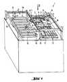
- the device 1has a closed substructure 10, on the upper side of which a number of functional devices are arranged.
- the substructurethere are all facilities that only have an indirect connection with the actual analysis processes, such as power supply, electronics, cuvette supply and disposal, cooling devices etc.
- first area 18On the top there is a first area 18, in which all reagents for pipetting are available, a second area 13 for setting up the sample containers from which the samples are pipetted into the measuring cuvettes, and a third area, which is the actual analysis area is.
- first area 18Above the first area 18 are transport devices 16, 17, each of which desires one or preferably two pipetting needles Run pipetting positions to allow for the pipetting of certain amounts of reagents held in the first area.
- the second areamay additionally contain a compartment 15 for holding components for special tests, e.g. for tests in which so-called ion-selective electrodes are used.
- a washing position 19is provided, in which the pipetting needle is cleaned between pipetting.
- a device 2 for the cuvette transport and a number of processing stations for the samples contained in the cuvettesare arranged in the analysis area.
- This analysis areais shown in plan view in FIG. 2. It contains the components described below.
- a cuvette transport device 2is a circular rotor which can be rotated by precise angular steps in both directions of rotation by a drive (not shown).
- the measuring cuvettesare held on the outer edge 3 of the rotor by lying on the one hand with a flange on their upper side on a flat ring surface perpendicular to the rotor axis and at the same time resting with one of their wall surfaces on the essentially cylindrical outer surface of the rotor, and on the other hand by everyone Resilient tongues assigned to the cuvette position and projecting radially over the cuvette are held, for this purpose they have on their underside a projection (not shown) which engages in a recess arranged in the cuvette flange.
- the cuvettesare held so firmly by the resilient holder that they cannot fall out of their own accord even when the rotor is rotating.
- the resilient holderallows the cuvettes to be removed or attached manually or by a mechanical gripping mechanism.
- the rotorleads the cuvettes past a photometer 9 to carry out absorption measurements.
- the cuvettespass through the light beam from the photometer.
- Processing stationsare arranged in precisely defined positions relative to the rotor. These processing stations are equipped with means for removing cuvettes from the rotor or for placing cuvettes on the rotor while it is stationary. The tasks of the processing stations are described in detail below. A detailed description of the processing stations for adding samples or reagents can be seen from European patent application No. 92.105901 with the title "Processing station of an analysis device". Reference is hereby made to this description.
- a processing station 4is responsible for the use of new cuvettes and for the removal of used cuvettes after the analysis has ended.
- the cuvettes removed from the rotorare placed in a waste container.
- a processing station 8is responsible for metering the reagents.
- One of the cuvettes on the rotoris removed and placed in a processing position in the station.
- One or more reagentsare pipetted into the cuvette.
- the amount of reagentis mixed by suitable cuvette movement. Then the cuvette with reagents is put back on the rotor.
- a processing station 6serves to predilute the sample.
- An empty cuvetteis removed from the rotor and placed in a processing position in the station.
- a specified amount of sample and dilution liquidare pipetted into the cuvette.
- the diluted sampleis mixed using a suitable cuvette movement. The cuvette is then placed back on the rotor.
- a processing station 5is responsible for sample dosing.
- One of the cuvettes on the rotoris removed and placed in one Machining position brought in the station.
- a predetermined amount of the diluted sampleis pipetted into the cuvette.
- the amount of reagentis mixed by suitable cuvette movement.
- the cuvette with the sample / reagent mixtureis then placed back on the rotor.
- a processing station 7is used to add a starting reagent to start the reaction of the sample.
- a cuvetteis removed from the rotor and placed in a processing position in the station.
- a predetermined amount of the starting reagentis pipetted into the cuvette.
- the sample / reagent mixtureis mixed by a suitable cuvette movement. The cuvette is then placed back on the rotor.
- a processing station 11is used to carry out a fluorescence polarimetric (FP) measurement.
- FPfluorescence polarimetric
- the sequence of a determination programis based on the example of an absorption measurement as follows:
- the processing station 4places a cuvette on the rotor for the requested determination. With this cuvette, an air measurement is first carried out on the rotor to test the cuvette.
- the cuvetteis removed from the rotor by the processing station 8 and brought into a pipetting position in the processing station.
- one or more reagentsare pipetted into the cuvette.
- mixingis carried out simultaneously with the pipetting and afterwards.
- the cuvetteis then placed back on the rotor.
- the cuvetteis removed from the rotor by the processing station 6 and brought into the pipetting position.
- the sample and a diluentare dosed through the sample transfer.
- Mixingis carried out simultaneously and / or afterwards and after use of the prediluted sample the cuvette is put back on the rotor.
- the cuvetteis removed from the rotor by the processing station 5 and brought into the pipetting position.
- the Sample dosed by the sample transferthen mixed and the cuvette placed back on the rotor.
- a T o measurementis then carried out on the rotor.
- the cuvetteis removed from the rotor by the processing station 7 and brought into the pipetting position.
- a starting reagentis metered in here, then mixed and the cuvette placed back on the rotor.
- the cuvetteis removed from the rotor by the processing station 4 and disposed of.
- An absorption measurementis carried out every 6 seconds while the cuvettes are on the rotor.
- the cuvetteis set back on the rotor after the sample has been added, it is removed again 132 seconds later by the processing station 11 and an FP empty measurement (parallel and vertical) is carried out.
- the cuvetteis again removed by the processing station 11, measured and then put back on the rotor.
- the rotormakes one complete revolution for the absorption measurement.
- the photometerilluminates the cuvettes with white light, which is then separated into twelve wavelengths. Any two values of these twelve wavelengths are stored for further processing. This results in a measuring point with two wavelengths every 6s for each cuvette.
Landscapes
- Chemical & Material Sciences (AREA)
- Chemical Kinetics & Catalysis (AREA)
- Physics & Mathematics (AREA)
- Health & Medical Sciences (AREA)
- Life Sciences & Earth Sciences (AREA)
- Analytical Chemistry (AREA)
- Biochemistry (AREA)
- General Health & Medical Sciences (AREA)
- General Physics & Mathematics (AREA)
- Immunology (AREA)
- Pathology (AREA)
- Automatic Analysis And Handling Materials Therefor (AREA)
- Sampling And Sample Adjustment (AREA)
Description
Translated fromGermanDie Erfindung betrifft eine Vorrichtung zur Durchführung von chemischen und biochemischen Analysen mit einem Transportrotor zum Transport von Probenküvetten, die am äusseren Rand des Rotors angeordnet sind, zu Bearbeitungsstationen, die zur Vornahme der für die Analysen erforderlichen Behandlungsschritte in definierten Positionen um den Rotor herum angeordnet sind, einer ersten Station für die Probendosierung, einer zweiten Station für die Reagenziendosierung, einer dritten Station für die Vornahme einer Fluoreszenzpolarimetrischen oder Absorptions-Messung, und ggf. weiterer Stationen.The invention relates to a device for carrying out chemical and biochemical analyzes with a transport rotor for transporting sample cells which are arranged on the outer edge of the rotor to processing stations which are arranged around the rotor in defined positions for carrying out the treatment steps required for the analyzes , a first station for sample dosing, a second station for reagent dosing, a third station for carrying out a fluorescence polarimetric or absorption measurement, and possibly further stations.
Automatische Analysenvorrichtungen arbeiten in der Regel nach dem Prinzip, dass die Analysenproben oder Teilmengen davon in Probenbehälter verbracht, anschliessend einer Reihe von Bearbeitungsschritten wie Zufügen (Pipettieren) von Reagenzien, Mischen, Inkubieren etc. unterworfen und dass entweder mehrmals während der Bearbeitung und/oder einmal am Ende der Bearbeitung Messungen der erfolgten Reaktionen vorgenommen werden. Dabei erfolgt der Ablauf üblicherweise entweder so, dass die Probenbehälter mit den Analysenproben in fester Reihenfolge auf einem Transportmittel angeordnet werden und verschiedene Bearbeitungsstationen durchlaufen oder dass bei der sog. Batch-Bearbeitung, wie sie bei den sog. Zentrifugalanalysengeräten üblich ist, alle auf einem Träger (Rotor) angeordneten Probenbehälter quasi gleichzeitig den Bearbeitungsschritten und den Messungen unterworfen werden. Nach diesen Prinzipien arbeitende Analysensysteme leisten gute Dienste in grossen Kliniken und Analysenzentren, in denen grosse Probenzahlen verarbeitet werden müssen.Automatic analysis devices generally work on the principle that the analysis samples or subsets thereof are placed in sample containers, then subjected to a series of processing steps such as adding (pipetting) reagents, mixing, incubating etc. and that either several times during processing and / or once measurements of the reactions that have taken place are carried out at the end of the processing. The process usually takes place either in such a way that the sample containers with the analysis samples are arranged in a fixed sequence on a means of transport and pass through various processing stations, or in the case of batch processing, as is common with the so-called centrifugal analysis devices, all on one carrier (Rotor) arranged sample containers are subjected to the processing steps and the measurements virtually simultaneously. Analysis systems based on these principles serve well in large clinics and analysis centers where large numbers of samples have to be processed.
Eine Vorrichtung zur photometrischen Analyse von Proben ist in US-A-3 322 958 beschrieben und enthält einen Drehtisch für den Transport von Probenbehältern zu einem unterhalb des Drehtisches angeordneten Photometer. Die Probenbehälter werden zur Messung in ihrer Position im Drehtisch soweit verschoben, dass sich ihr unteres Ende in die Messzone des Photometers erstreckt. Nach erfolgter Messung werden die Probenbehälter wieder auf ihr ursprüngliches Niveau auf dem Drehtisch angehoben.A device for the photometric analysis of samples is described in US-A-3 322 958 and contains a turntable for the transport of sample containers to a photometer arranged below the turntable. The sample containers are moved in their position on the turntable for measurement so that their lower end extends into the measuring zone of the photometer. After the measurement, the sample containers are raised to their original level on the turntable.
Eine Vorrichtung zur Blutanalyse ist in EP-A-99 103 beschrieben und enthält vor allem eine Rühr- bzw. Mischeinrichtung, in der die einzelnen Probenbehälter einer Bewegung unterworfen werden, die einen Mischeffekt bewirkt. Die Zuführung der Proben zur eigentlichen Testeinrichtung 50 erfolgt durch Entnahme, d.h. Absaugen der Probe aus dem Probenbehälter.A device for blood analysis is described in EP-A-99 103 and contains above all a stirring or mixing device in which the individual sample containers are subjected to a movement which brings about a mixing effect. The samples are fed to the actual test device 50 by removal, i.e. Aspirate the sample from the sample container.
Eine andere Vorrichtung mit einem Transportrotor zum Transport von Küvetten zu einzelnen um den Rotor herum angeordneten Bearbeitungsstationen ist in US-A-4,785,407 beschrieben. Die auf dem Rotor angeordneten Küvetten werden sequentiell zu den Bearbeitungsstationen geführt. Bei den Stationen bleiben die Küvetten während der Bearbeitung auf dem Rotor.Another device with a transport rotor for transporting cuvettes to individual processing stations arranged around the rotor is described in US-A-4,785,407. The cuvettes arranged on the rotor are sequentially guided to the processing stations. At the stations, the cuvettes remain on the rotor during processing.
Eine Vorrichtung mit Transportketten zum Küvettentransport ist in US-A-3,644,095 beschrieben. Auch dieses Transportsystem arbeitet sequentiell. Zur Vornahme der wesentlichen Bearbeitungsschritte Proben- und Reagenziendosierung und Messung bleiben die Küvetten auf den Transportketten, oder die Probenmischung wird aus den Küvetten entnommen. Zur Ermöglichung einer grösseren Verweildauer werden die Küvetten von den Transportketten entnommen und temporär auf einen als eine Art Warteschleife dienenden Rotor gesetzt.A device with transport chains for cuvette transport is described in US-A-3,644,095. This transport system also works sequentially. To carry out the essential processing steps of sample and reagent dosing and measurement, the cuvettes remain on the transport chains or the sample mixture is removed from the cuvettes. To enable a longer dwell time, the cuvettes are removed from the transport chains and temporarily placed on a rotor which serves as a kind of holding pattern.
Es hat sich aber angesichts der heutigen Vielfalt der möglichen Analysen und der medizinischen Anforderungen, vor allem im Bereich der klinischen Chemie herausgestellt, dass die bisher üblichen für den sequentiellen Durchsatz grosser Probenmengen geeigneten Analysenautomaten zu wenig flexibel sind, um auf einzelne Patienten bzw. Krankheitsbilder spezifisch zugeschnittene Analysenprofile (Fall Random Access) zu erstellen und trotzdem eine grosse Zahl von Patientenproben zu bewältigen.However, in view of the current variety of possible analyzes and the medical requirements, especially in the field of clinical chemistry, it has emerged that the automatic analyzers that were previously customary for the sequential throughput of large sample quantities are not flexible enough to be specific to individual patients or clinical pictures Create tailored analysis profiles (Random Access case) and still manage a large number of patient samples.
Der Erfindung liegt daher die Aufgabe zugrunde, ein Analysensystem bereitzustellen, das diesen Anforderungen Rechnung trägt, indem eine grosse Zahl von Analysenproben mit grösster Flexibilität bezüglich des an der einzelnen Probe durchgeführten Analysenprofils verarbeitet werden können.The invention is therefore based on the object of providing an analysis system which takes these requirements into account, in that a large number of analysis samples can be processed with the greatest flexibility with regard to the analysis profile carried out on the individual sample.
Erfindungsgemäss wird dies dadurch erreicht, dass bei den Stationen Entnahmemittel zur Entfernung der Küvetten vom Rotor, zur Verbringung der Küvetten in die Bearbeitungsstationen und zum Zurücksetzen der Küvetten nach einer Bearbeitung auf den Transportrotor vorhanden sind und dass der Transportrotor mit einem Antrieb zur Drehung um genaue Winkelschritte in beide Drehrichtungen versehen ist.This is achieved according to the invention in that the stations have removal means for removing the cuvettes from the rotor, for moving the cuvettes into the processing stations and for resetting the cuvettes after processing on the transport rotor, and for the transport rotor to be driven by precise angular steps for rotation is provided in both directions.
Im folgenden wird anhand der beiliegenden Zeichnungen ein Ausführungsbeispiel der Erfindung beschrieben.In the following an embodiment of the invention will be described with reference to the accompanying drawings.
Es zeigen:
- Fig. 1
- eine axonometrische Gesamtdarstellung einer Analysen vorrichtung
- Fig. 2
- eine Draufsicht auf die Vorrichtung gemäss Pfeil I in Fig. 1
- Fig. 1
- an overall axonometric representation of an analysis device
- Fig. 2
- a plan view of the device according to arrow I in Fig. 1st
Wie aus Fig. 1 ersichtlich besitzt die Vorrichtung 1 einen geschlossenen Unterbau 10, auf dessen Oberseite eine Anzahl von funktionellen Einrichtungen angeordnet ist. Im Unterbau befinden sich alle Einrichtungen, die mit den eigentlichen Analysenvorgängen nur indirekt zu tun haben, wie beispielsweise Stromversorgung, Elektronik, Küvettenver- und entsorgung, Kühleinrichtungen etc.As can be seen from FIG. 1, the
Auf der Oberseite befindet sich ein erster Bereich 18, in dem alle Reagenzien zur Pipettierung zur Verfügung gehalten werden, ein zweiter Bereich 13 für die Aufstellung der Probenbehälter, aus denen die Proben in die Messküvetten pipettiert werden, und ein dritter Bereich, welcher der eigentliche Analysenbereich ist.On the top there is a
Oberhalb des ersten Bereiches 18 sind Transporteinrichtungen 16, 17, die je eine oder vorzugsweise zwei Pipettiernadel zu gewünschten Pipettierpositionen führen, um die Pipettierung bestimmter Mengen von Reagenzien zu ermöglichen, die im ersten Bereich gehalten werden.Above the
Oberhalb des zweiten Bereiches 13 sind Transporteinrichtungen 12, 14, die je eine oder vorzugsweise zwei Pipettiernadel zu gewünschten Pipettierpositionen führen, um die Pipettierung bestimmter Mengen von Proben aus Probenbehälter zu ermöglichen, die im ersten Bereich gehalten werden.Above the
Der zweite Bereich kann zusätzlich einen Fach 15 zur Aufnahme von Komponenten für speziellen Tests enthalten, z.B. für Tests bei denen sogenannte ionselektive Elektroden verwendet werden.The second area may additionally contain a
Neben dem ersten Bereich 18 und dem zweiten Bereich 13 ist je eine Waschposition 19 vorgesehen, in der die Pipettiernadel zwischen Pipettierungen gereinigt wird.In addition to the
In dem Analysenbereich sind eine Vorrichtung 2 für den Küvettentransport, sowie eine Anzahl von Bearbeitungsstationen für die in den Küvetten enthaltenen Proben angeordnet. Dieser Analysenbereich ist in Fig. 2 in Draufsicht gezeigt. Er enthält die nachstehend beschriebenen Komponenten.A
Als Küvettentransportvorrichtung 2 dient ein kreisförmiger, durch einen (nicht gezeigten) Antrieb um genaue Winkelschritte in beiden Drehrichtungen drehbarer Rotor. Die Messküvetten werden am äusseren Rand 3 des Rotors gehalten, indem sie einerseits mit einem an ihrer Oberseite vorhandenen Flansch auf einer ebenen, zur Rotorachse senkrechten Ringfläche aufliegen und gleichzeitig mit einer ihrer Wandflächen an der im wesentlichen zylindrischen Aussenfläche des Rotors anliegen, sowie andererseits durch jeder Küvettenposition zugeordnete, radial über die Küvette ragende federnde Zungen gehalten werden, die zu diesem Zweck auf ihrer Unterseite einen, in eine im Küvettenflansch angeordnete Vertiefung eingreifenden Vorsprung (nicht gezeigt) aufweisen. Durch die federnde Halterung werden die Küvetten so fest gehalten, dass sie auch bei Rotordrehung nicht von selbst herausfallen können. Andererseits erlaubt es die federnde Halterung, die Küvetten manuell oder durch einen mechanischen Greifmechanismus einfach abzunehmen oder aufzustecken.A
Eine detaillierte Beschreibung des Rotors 2 und seiner Funktion ist aus der europäischen Patentanmeldung Nr. 92.105902 mit dem Titel "Transporteinrichtung für eine Analysenvorrichtung" ersichtlich. Auf diese Beschreibung wird hiermit Bezug genommen.A detailed description of the
Der Rotor führt die Küvetten an einem Photometer 9 zur Durchführung von Absorptionsmessungen vorbei. Die Küvetten durchlaufen den Lichtstrahl des Photometers.The rotor leads the cuvettes past a
In genau definierten Positionen relativ zum Rotor sind Bearbeitungsstationen angeordnet. Diese Bearbeitungsstationen sind mit Mitteln zur Entnahme von Küvetten vom Rotor und oder zum Aufsetzen von Küvetten auf den Rotor während dessen Stillstand ausgestattet. Die Aufgaben der Bearbeitungsstationen werden nachfolgend im einzelnen beschrieben. Eine detaillierte Beschreibung der Bearbeitungsstationen zur Proben- oder Reagenzienzugabe ist aus der europäischen Patentanmeldung Nr. 92.105901 mit dem Titel "Bearbeitungsstation einer Analysenvorrichtung" ersichtlich. Auf diese Beschreibung wird hiermit Bezug genommen.Processing stations are arranged in precisely defined positions relative to the rotor. These processing stations are equipped with means for removing cuvettes from the rotor or for placing cuvettes on the rotor while it is stationary. The tasks of the processing stations are described in detail below. A detailed description of the processing stations for adding samples or reagents can be seen from European patent application No. 92.105901 with the title "Processing station of an analysis device". Reference is hereby made to this description.
Eine Bearbeitungsstation 4 ist für den Einsatz neuer Küvetten und für die Entfernung gebrauchter Küvetten nach beendeter Analyse zuständig. Die aus dem Rotor entfernten Küvetten werden in einen Abfallbehälter gebracht.A processing station 4 is responsible for the use of new cuvettes and for the removal of used cuvettes after the analysis has ended. The cuvettes removed from the rotor are placed in a waste container.
Eine Bearbeitungsstation 8 ist für die Reagenziendosierung zuständig. Eine der auf dem Rotor befindlichen Küvetten wird abgenommen und in eine Bearbeitungsposition in der Station gebracht. Ein oder mehrere Reagenzien werden in die Küvette pipettiert. Gleichzeitig wird durch geeignete Küvettenbewegung die Reagenzienmenge gemischt. Danach wird die mit Reagenzien versehene Küvette auf den Rotor zurückgesetzt.A
Eine Bearbeitungsstation 6 dient der Vorverdünnung der Probe. Eine leere Küvette wird vom Rotor abgenommen und in eine Bearbeitungsposition in der Station gebracht. Eine vorgegebene Probenmenge und Verdünnungsflüssigkeit werden in die Küvette pipettiert. Gleichzeitig wird die durch geeignete Küvettenbewegung die verdünnte Probe gemischt. Danach wird die Küvette auf den Rotor zurückgesetzt.A
Eine Bearbeitungsstation 5 ist für die Probendosierung zuständig. Eine der auf dem Rotor befindlichen Küvetten wird abgenommen und in eine Bearbeitungsposition in der Station gebracht. Eine vorgegebene Menge der verdünnten Probe wird in die Küvette pipettiert. Gleichzeitig wird durch geeignete Küvettenbewegung die Reagenzienmenge gemischt. Danach wird die mit Proben/Reagenzien-Mischung versehene Küvette auf den Rotor zurückgesetzt.A
Eine Bearbeitungsstation 7 dient der Zugabe eines Startreagens für den Beginn der Reaktion der Probe. Eine Küvette wird vom Rotor abgenommen und in eine Bearbeitungsposition in der Station gebracht. Eine vorgegebene Menge des Startreagens wird in die Küvette pipettiert. Gleichzeitig wird durch geeignete Küvettenbewegung die Proben/Reagenzien-Mischung gemischt. Danach wird die Küvette auf den Rotor zurückgesetzt.A
Eine Bearbeitungsstation 11 dient zur Durchführung einer fluoreszenzpolarimetrische (FP) Messung. Eine mit Proben/Reagenzien-Mischung versehenen Probe wird vom Rotor abgenommen und in eine Messkammer in der Station gebracht. Nach der Messung wird die Küvette auf den Rotor zurückgesetzt.A
Der Ablauf eines Bestimmungsprogramms stellt sich am Beispiel einer Absorptionsmessung wie folgt dar:The sequence of a determination program is based on the example of an absorption measurement as follows:
Für die angeforderte Bestimmung wird durch die Bearbeitungsstation 4 eine Küvette auf den Rotor aufgesetzt. Auf dem Rotor wird mit dieser Küvette als erstes eine Luftmessung zur Prüfung der Küvette durchgeführt.The processing station 4 places a cuvette on the rotor for the requested determination. With this cuvette, an air measurement is first carried out on the rotor to test the cuvette.
30 Sekunden später wird die Küvette durch die Bearbeitungsstation 8 vom Rotor abgenommen und in eine Pipettierposition in der Bearbeitungsstation gebracht. Hier werden ein oder mehrere Reagenzien in die Küvette pipettiert. Im Fall von mehreren Reagenzien wird gleichzeitig mit der Pipettierung und danach gemischt. Anschliessend wird die Küvette auf den Rotor zurückgesetzt.30 seconds later, the cuvette is removed from the rotor by the
72 Sekunden später wird die Küvette durch die Bearbeitungsstation 6 vom Rotor abgenommen und in die Pipettierposition gebracht. Hier wird die Probe und ein Verdünnungsmittel durch den Probentransfer dosiert. Gleichzeitig und/oder danach wird gemischt und nach Verwendung der vorverdünnten Probe wird die Küvette auf den Rotor zurückgesetzt.72 seconds later, the cuvette is removed from the rotor by the
6 Sekunden später wird die Küvette durch die Bearbeitungsstation 5 vom Rotor abgenommen und in die Pipettierposition gebracht. Hier wird die Probe durch den Probentransfer dosiert, danach gemischt und die Küvette auf den Rotor zurückgesetzt. Anschliessend wird auf dem Rotor eine To-Messung durchgeführt.6 seconds later, the cuvette is removed from the rotor by the
162 Sekunden später wird die Küvette durch die Bearbeitungsstation 7 vom Rotor abgenommen und in die Pipettierposition gebracht. Hier wird ein Startreagens zudosiert, danach gemischt und die Küvette auf den Rotor zurückgesetzt.162 seconds later, the cuvette is removed from the rotor by the
324 Sekunden später wird die Küvette durch die Bearbeitungsstation 4 vom Rotor abgenommen und entsorgt.324 seconds later, the cuvette is removed from the rotor by the processing station 4 and disposed of.
Während sich die Küvetten auf dem Rotor befinden wird alle 6 Sekunden eine Absorptionsmessung durchgeführt.An absorption measurement is carried out every 6 seconds while the cuvettes are on the rotor.
Zu diesem Ablauf kommen für fluoreszenzpolarimetrische (FP) Messungen nach zwei Behandlungsphasen hinzu.This process is followed by fluorescence polarimetric (FP) measurements after two treatment phases.
Wenn die Küvette nach der Probenzugabe auf den Rotor zurückgesetzt ist wird sie 132 Sekunden später durch die Bearbeitungsstation 11 wieder entnommen und eine FP-Leermessung (parallel und senkrecht) durchgeführt.If the cuvette is set back on the rotor after the sample has been added, it is removed again 132 seconds later by the
Entsprechend wird 90 Sekunden nachdem die Küvette mit dem zudosierten Startregens auf den Rotor zurückgesetzt ist, die Küvette erneut durch die Bearbeitungsstation 11 entnommen, gemessen und danach auf den Rotor zurückgesetzt.Correspondingly, 90 seconds after the cuvette with the metered starting rain is put back on the rotor, the cuvette is again removed by the
Während der Pipettierzeit in den Bearbeitungsstationen führt der Rotor eine ganze Umdrehung für die Absorptionsmessung aus. Das Photometer durchstrahlt die Küvetten mit weissem Licht, das anschliessend in zwölf Wellenlängen aufgetrennt wird. Zwei beliebige Werte dieser zwölf Wellenlängen werden für die weitere Verarbeitung gespeichert. Dadurch ergibt sich für jede Küvette alle 6s ein Messpunkt mit zwei Wellenlängen.During the pipetting time in the processing stations, the rotor makes one complete revolution for the absorption measurement. The photometer illuminates the cuvettes with white light, which is then separated into twelve wavelengths. Any two values of these twelve wavelengths are stored for further processing. This results in a measuring point with two wavelengths every 6s for each cuvette.
Claims (2)
- A device for performing chemical and biochemical analyses, having- a conveying rotor for conveying sample cuvettes positioned at the outer periphery of the rotor to processing stations which for performing the processing steps necessary for the analysis are arranged around the rotor at defined positions- a first station for the metering of samples- a second station for the metering of reagents- a third station for performing a fluorescence-polarimetric or absorption measurement and possibly further stations,characterized in that at the stations there are removing means for removing the cuvettes from the rotor, for transferring the cuvettes into the processing stations and for returning the cuvettes to the conveying rotor after processing and that the conveying rotor is provided with a drive for rotation by exact angular steps in both rotary directions.
- A device according to claim 1, characterized in that the removing means each are part of the processing stations.
Applications Claiming Priority (2)
| Application Number | Priority Date | Filing Date | Title |
|---|---|---|---|
| EP92105903 | 1992-04-06 | ||
| EP92105903 | 1992-04-06 |
Publications (2)
| Publication Number | Publication Date |
|---|---|
| EP0564907A1 EP0564907A1 (en) | 1993-10-13 |
| EP0564907B1true EP0564907B1 (en) | 1997-05-28 |
Family
ID=8209512
Family Applications (1)
| Application Number | Title | Priority Date | Filing Date |
|---|---|---|---|
| EP93104847AExpired - LifetimeEP0564907B1 (en) | 1992-04-06 | 1993-03-24 | Analyser |
Country Status (5)
| Country | Link |
|---|---|
| US (1) | US5762872A (en) |
| EP (1) | EP0564907B1 (en) |
| JP (1) | JP3131068B2 (en) |
| CA (1) | CA2093508A1 (en) |
| DE (1) | DE59306558D1 (en) |
Families Citing this family (22)
| Publication number | Priority date | Publication date | Assignee | Title |
|---|---|---|---|---|
| US5772962A (en)* | 1995-05-29 | 1998-06-30 | Hitachi, Ltd. | Analyzing apparatus using disposable reaction vessels |
| KR100704324B1 (en) | 1998-05-01 | 2007-04-09 | 젠-프로브 인코포레이티드 | Automated Analytical Instruments and Automated Analytical Methods |
| US8337753B2 (en) | 1998-05-01 | 2012-12-25 | Gen-Probe Incorporated | Temperature-controlled incubator having a receptacle mixing mechanism |
| US6919044B1 (en)* | 1999-06-17 | 2005-07-19 | Beckman Coulter, Inc. | Sample loading and handling interface to multiple chemistry analyzers |
| USD474416S1 (en) | 2002-02-28 | 2003-05-13 | Hitachi High-Technologies | Biochemical analysis machine |
| US8398656B2 (en) | 2003-01-30 | 2013-03-19 | Integrated Vascular Systems, Inc. | Clip applier and methods of use |
| JP3972012B2 (en) | 2003-03-19 | 2007-09-05 | 株式会社日立ハイテクノロジーズ | Sample dispensing mechanism and automatic analyzer equipped with the same |
| EP1615037A1 (en)* | 2004-07-06 | 2006-01-11 | Boehringer Mannheim Gmbh | An apparatus for liquid handling with multiple transfer tools |
| CA2967430C (en) | 2005-03-10 | 2018-05-08 | Gen-Probe Incorporated | Systems and methods to perform assays for detecting or quantifying analytes within samples |
| US8313497B2 (en) | 2005-07-01 | 2012-11-20 | Abbott Laboratories | Clip applier and methods of use |
| ITMI20061502A1 (en)* | 2006-07-28 | 2008-01-29 | Barilla Flli G & R Spa | PROCEDURE AND EQUIPMENT FOR THE QUICK DETERMINATION OF DEOSSINIVALENOL IN A CEREAL-BASED MATRIX. |
| US7641855B2 (en)* | 2006-08-25 | 2010-01-05 | Siemens Healthcare Diagnostics Inc. | System for automatically storing and reprocessing patient samples in an automatic clinical analyzer |
| US9486191B2 (en) | 2009-01-09 | 2016-11-08 | Abbott Vascular, Inc. | Closure devices |
| JP5286120B2 (en)* | 2009-03-18 | 2013-09-11 | 株式会社日立ハイテクノロジーズ | Automatic analyzer |
| US9046507B2 (en) | 2010-07-29 | 2015-06-02 | Gen-Probe Incorporated | Method, system and apparatus for incorporating capacitive proximity sensing in an automated fluid transfer procedure |
| AU2012222178B2 (en) | 2011-02-24 | 2014-12-18 | Gen-Probe Incorporated | Systems and methods for distinguishing optical signals of different modulation frequencies in an optical signal detector |
| US8556932B2 (en) | 2011-05-19 | 2013-10-15 | Abbott Cardiovascular Systems, Inc. | Collapsible plug for tissue closure |
| US9364209B2 (en) | 2012-12-21 | 2016-06-14 | Abbott Cardiovascular Systems, Inc. | Articulating suturing device |
| JP6165961B2 (en) | 2013-03-15 | 2017-07-19 | アボット・ラボラトリーズAbbott Laboratories | Diagnostic analyzer with pre-process carousel and associated method |
| WO2014144640A1 (en) | 2013-03-15 | 2014-09-18 | Abbott Laboratories | Automated diagnostic analyzers having vertically arranged carousels and related methods |
| CN107831324B (en) | 2013-03-15 | 2021-11-19 | 雅培制药有限公司 | Automated diagnostic analyzer with rear accessible track system and related methods |
| FR3048510B1 (en) | 2016-03-01 | 2020-01-31 | Arteion | AUTOMATIC ANALYSIS SYSTEM FOR IN VITRO DIAGNOSIS |
Citations (2)
| Publication number | Priority date | Publication date | Assignee | Title |
|---|---|---|---|---|
| US3644095A (en)* | 1967-12-20 | 1972-02-22 | Eppendorf Geractebau Netheler | Apparatus for performing chemical analyses |
| US4785407A (en)* | 1985-11-19 | 1988-11-15 | Olympus Optical Co., Ltd. | Automatic chemical analyzer with selective removal of reaction vessels |
Family Cites Families (14)
| Publication number | Priority date | Publication date | Assignee | Title |
|---|---|---|---|---|
| US3115966A (en)* | 1959-05-04 | 1963-12-31 | Leiter Harry | Sample testing machine |
| US3322958A (en)* | 1964-05-07 | 1967-05-30 | American Instr Co Inc | Photometer automatic sample changer |
| US3432049A (en)* | 1967-02-20 | 1969-03-11 | Elliotts Liverpool Ltd | Apparatus for automatically feeding articles from a store or batch |
| US4582990A (en)* | 1980-10-27 | 1986-04-15 | Randam Electronics, Inc. | Analytical instrument with two moving trains of sample holder-carrying trays under microprocessor control |
| US4518264A (en)* | 1982-07-13 | 1985-05-21 | Mitsubishi Kasei Kogyo Kabushiki Kaisha | Stirring apparatus |
| JPS60174866U (en)* | 1984-04-27 | 1985-11-19 | 三共株式会社 | Reaction liquid stirring and mixing device in automatic measurement equipment |
| JPS61274268A (en)* | 1985-05-30 | 1986-12-04 | Toshiba Corp | automatic chemical analyzer |
| JPH0786509B2 (en)* | 1985-06-18 | 1995-09-20 | 株式会社東芝 | Automatic chemical analyzer |
| CN1014551B (en)* | 1986-09-16 | 1991-10-30 | 尼泰库株式会社 | Automatic analyser |
| US4861553A (en)* | 1987-06-11 | 1989-08-29 | Technicon Instruments Corporation | Automatic sampling system |
| US5066135A (en)* | 1988-08-09 | 1991-11-19 | Beckman Instruments, Inc. | Rotatable vortexing turntable |
| GB9020352D0 (en)* | 1990-09-18 | 1990-10-31 | Anagen Ltd | Assay or reaction apparatus |
| CA2092025A1 (en)* | 1992-04-06 | 1993-10-07 | Bruno Koch | Conveyor for an analytical device |
| CA2092026A1 (en)* | 1992-04-06 | 1993-10-07 | Burkard Rosenberg | Processing station for an analytical device |
- 1993
- 1993-03-24EPEP93104847Apatent/EP0564907B1/ennot_activeExpired - Lifetime
- 1993-03-24DEDE59306558Tpatent/DE59306558D1/ennot_activeExpired - Lifetime
- 1993-04-05JPJP05077310Apatent/JP3131068B2/ennot_activeExpired - Fee Related
- 1993-04-06CACA002093508Apatent/CA2093508A1/ennot_activeAbandoned
- 1997
- 1997-07-23USUS08/899,461patent/US5762872A/ennot_activeExpired - Lifetime
Patent Citations (2)
| Publication number | Priority date | Publication date | Assignee | Title |
|---|---|---|---|---|
| US3644095A (en)* | 1967-12-20 | 1972-02-22 | Eppendorf Geractebau Netheler | Apparatus for performing chemical analyses |
| US4785407A (en)* | 1985-11-19 | 1988-11-15 | Olympus Optical Co., Ltd. | Automatic chemical analyzer with selective removal of reaction vessels |
Also Published As
| Publication number | Publication date |
|---|---|
| JP3131068B2 (en) | 2001-01-31 |
| US5762872A (en) | 1998-06-09 |
| DE59306558D1 (en) | 1997-07-03 |
| CA2093508A1 (en) | 1993-10-07 |
| EP0564907A1 (en) | 1993-10-13 |
| JPH0618533A (en) | 1994-01-25 |
Similar Documents
| Publication | Publication Date | Title |
|---|---|---|
| EP0564907B1 (en) | Analyser | |
| AT401581B (en) | AUTOMATIC ANALYZER FOR PATIENT SAMPLES | |
| EP0043079B1 (en) | Automatic analysis apparatus | |
| DE69735176T2 (en) | Analyzer for multiple analyzes with multiple test modules | |
| DE69733927T2 (en) | METHOD AND DEVICE FOR PRE-TREATING SAMPLE IN A CHEMICAL ANALYZER | |
| DE68918962T2 (en) | Method and device for carrying out analyzes with the possibility of quantity. | |
| DE3030879C2 (en) | Automatic analyzer | |
| DE69429889T2 (en) | Automatic blood analysis system | |
| DE3546659C2 (en) | ||
| DE69308957T2 (en) | Method and device for handling samples | |
| DE60218787T2 (en) | Clinical analyzer with non-washing reagent dispenser | |
| DE2755264C3 (en) | Chemical analysis facility | |
| DE69737052T2 (en) | Automated device for performing biochemical analyzes | |
| DE69125797T2 (en) | Analysis method and device for liquid samples | |
| DE60210406T2 (en) | INCREASING THE THROUGHPUT IN AN AUTOMATIC CLINICAL ANALYZER BY SHARING ASSAYS BY TYPE | |
| DE60309104T2 (en) | Automatic analyzer | |
| DE69634553T2 (en) | A method of automatic analysis using a variety of reagents and apparatus therefor | |
| DE3014201A1 (en) | AUTOMATIC ANALYZER FOR LIQUID SAMPLES | |
| DE3402304C2 (en) | ||
| DE3717907A1 (en) | AUTOMATIC SAMPLING DEVICE FOR AUTOMATIC CHEMICAL ANALYZERS | |
| DE2349927A1 (en) | SMALL, DYNAMIC, MULTIPLE STATION PHOTOMETER WITH DISPOSABLE CUVETTE ROTOR | |
| DE3877453T2 (en) | ANALYZER WITH WASHING STATION SEPARATED FROM THE INCUBATOR. | |
| DE4231172C2 (en) | Automatic clinical analysis analyzer | |
| DE69515565T2 (en) | Analyzer | |
| DE3346532A1 (en) | Method of controlling an analyser for chemical analyses |
Legal Events
| Date | Code | Title | Description |
|---|---|---|---|
| PUAI | Public reference made under article 153(3) epc to a published international application that has entered the european phase | Free format text:ORIGINAL CODE: 0009012 | |
| 17P | Request for examination filed | Effective date:19930324 | |
| AK | Designated contracting states | Kind code of ref document:A1 Designated state(s):BE CH DE DK ES FR GB GR IE IT LI LU NL PT | |
| 17Q | First examination report despatched | Effective date:19940805 | |
| GRAG | Despatch of communication of intention to grant | Free format text:ORIGINAL CODE: EPIDOS AGRA | |
| GRAH | Despatch of communication of intention to grant a patent | Free format text:ORIGINAL CODE: EPIDOS IGRA | |
| GRAH | Despatch of communication of intention to grant a patent | Free format text:ORIGINAL CODE: EPIDOS IGRA | |
| GRAA | (expected) grant | Free format text:ORIGINAL CODE: 0009210 | |
| ITF | It: translation for a ep patent filed | ||
| AK | Designated contracting states | Kind code of ref document:B1 Designated state(s):BE CH DE DK ES FR GB GR IE IT LI LU NL PT | |
| PG25 | Lapsed in a contracting state [announced via postgrant information from national office to epo] | Ref country code:NL Free format text:LAPSE BECAUSE OF FAILURE TO SUBMIT A TRANSLATION OF THE DESCRIPTION OR TO PAY THE FEE WITHIN THE PRESCRIBED TIME-LIMIT Effective date:19970528 Ref country code:GR Free format text:LAPSE BECAUSE OF FAILURE TO SUBMIT A TRANSLATION OF THE DESCRIPTION OR TO PAY THE FEE WITHIN THE PRESCRIBED TIME-LIMIT Effective date:19970528 Ref country code:GB Effective date:19970528 Ref country code:ES Free format text:THE PATENT HAS BEEN ANNULLED BY A DECISION OF A NATIONAL AUTHORITY Effective date:19970528 Ref country code:DK Effective date:19970528 | |
| REG | Reference to a national code | Ref country code:CH Ref legal event code:EP | |
| REF | Corresponds to: | Ref document number:59306558 Country of ref document:DE Date of ref document:19970703 | |
| PG25 | Lapsed in a contracting state [announced via postgrant information from national office to epo] | Ref country code:PT Effective date:19970828 | |
| ET | Fr: translation filed | ||
| NLV1 | Nl: lapsed or annulled due to failure to fulfill the requirements of art. 29p and 29m of the patents act | ||
| GBV | Gb: ep patent (uk) treated as always having been void in accordance with gb section 77(7)/1977 [no translation filed] | Effective date:19970528 | |
| PG25 | Lapsed in a contracting state [announced via postgrant information from national office to epo] | Ref country code:LU Free format text:LAPSE BECAUSE OF NON-PAYMENT OF DUE FEES Effective date:19980324 | |
| PG25 | Lapsed in a contracting state [announced via postgrant information from national office to epo] | Ref country code:IE Free format text:LAPSE BECAUSE OF NON-PAYMENT OF DUE FEES Effective date:19980330 | |
| PG25 | Lapsed in a contracting state [announced via postgrant information from national office to epo] | Ref country code:LI Free format text:LAPSE BECAUSE OF NON-PAYMENT OF DUE FEES Effective date:19980331 Ref country code:CH Free format text:LAPSE BECAUSE OF NON-PAYMENT OF DUE FEES Effective date:19980331 Ref country code:BE Free format text:LAPSE BECAUSE OF NON-PAYMENT OF DUE FEES Effective date:19980331 | |
| PLBE | No opposition filed within time limit | Free format text:ORIGINAL CODE: 0009261 | |
| REG | Reference to a national code | Ref country code:IE Ref legal event code:FD4D Ref document number:74272 Country of ref document:IE | |
| 26N | No opposition filed | ||
| BERE | Be: lapsed | Owner name:F. HOFFMANN-LA ROCHE A.G. Effective date:19980331 | |
| REG | Reference to a national code | Ref country code:CH Ref legal event code:PL | |
| PGFP | Annual fee paid to national office [announced via postgrant information from national office to epo] | Ref country code:IT Payment date:20100317 Year of fee payment:18 Ref country code:FR Payment date:20100318 Year of fee payment:18 | |
| PGFP | Annual fee paid to national office [announced via postgrant information from national office to epo] | Ref country code:DE Payment date:20100331 Year of fee payment:18 | |
| REG | Reference to a national code | Ref country code:FR Ref legal event code:ST Effective date:20111130 | |
| PG25 | Lapsed in a contracting state [announced via postgrant information from national office to epo] | Ref country code:FR Free format text:LAPSE BECAUSE OF NON-PAYMENT OF DUE FEES Effective date:20110331 Ref country code:DE Free format text:LAPSE BECAUSE OF NON-PAYMENT OF DUE FEES Effective date:20111001 | |
| REG | Reference to a national code | Ref country code:DE Ref legal event code:R119 Ref document number:59306558 Country of ref document:DE Effective date:20111001 | |
| PG25 | Lapsed in a contracting state [announced via postgrant information from national office to epo] | Ref country code:IT Free format text:LAPSE BECAUSE OF NON-PAYMENT OF DUE FEES Effective date:20110324 |