EP0560368B1 - Process for on-line cleaning and filling of an extra corporeal blood circuit of a dialysis apparatus - Google Patents
Process for on-line cleaning and filling of an extra corporeal blood circuit of a dialysis apparatusDownload PDFInfo
- Publication number
- EP0560368B1 EP0560368B1EP93103965AEP93103965AEP0560368B1EP 0560368 B1EP0560368 B1EP 0560368B1EP 93103965 AEP93103965 AEP 93103965AEP 93103965 AEP93103965 AEP 93103965AEP 0560368 B1EP0560368 B1EP 0560368B1
- Authority
- EP
- European Patent Office
- Prior art keywords
- blood
- venous
- process according
- pump
- fluid
- Prior art date
- Legal status (The legal status is an assumption and is not a legal conclusion. Google has not performed a legal analysis and makes no representation as to the accuracy of the status listed.)
- Expired - Lifetime
Links
Images

Classifications
- A—HUMAN NECESSITIES
- A61—MEDICAL OR VETERINARY SCIENCE; HYGIENE
- A61M—DEVICES FOR INTRODUCING MEDIA INTO, OR ONTO, THE BODY; DEVICES FOR TRANSDUCING BODY MEDIA OR FOR TAKING MEDIA FROM THE BODY; DEVICES FOR PRODUCING OR ENDING SLEEP OR STUPOR
- A61M1/00—Suction or pumping devices for medical purposes; Devices for carrying-off, for treatment of, or for carrying-over, body-liquids; Drainage systems
- A61M1/36—Other treatment of blood in a by-pass of the natural circulatory system, e.g. temperature adaptation, irradiation ; Extra-corporeal blood circuits
- A61M1/3621—Extra-corporeal blood circuits
- A61M1/3643—Priming, rinsing before or after use
- A—HUMAN NECESSITIES
- A61—MEDICAL OR VETERINARY SCIENCE; HYGIENE
- A61M—DEVICES FOR INTRODUCING MEDIA INTO, OR ONTO, THE BODY; DEVICES FOR TRANSDUCING BODY MEDIA OR FOR TAKING MEDIA FROM THE BODY; DEVICES FOR PRODUCING OR ENDING SLEEP OR STUPOR
- A61M1/00—Suction or pumping devices for medical purposes; Devices for carrying-off, for treatment of, or for carrying-over, body-liquids; Drainage systems
- A61M1/14—Dialysis systems; Artificial kidneys; Blood oxygenators ; Reciprocating systems for treatment of body fluids, e.g. single needle systems for hemofiltration or pheresis
- A61M1/16—Dialysis systems; Artificial kidneys; Blood oxygenators ; Reciprocating systems for treatment of body fluids, e.g. single needle systems for hemofiltration or pheresis with membranes
- A61M1/1601—Control or regulation
- A—HUMAN NECESSITIES
- A61—MEDICAL OR VETERINARY SCIENCE; HYGIENE
- A61M—DEVICES FOR INTRODUCING MEDIA INTO, OR ONTO, THE BODY; DEVICES FOR TRANSDUCING BODY MEDIA OR FOR TAKING MEDIA FROM THE BODY; DEVICES FOR PRODUCING OR ENDING SLEEP OR STUPOR
- A61M1/00—Suction or pumping devices for medical purposes; Devices for carrying-off, for treatment of, or for carrying-over, body-liquids; Drainage systems
- A61M1/34—Filtering material out of the blood by passing it through a membrane, i.e. hemofiltration or diafiltration
- A61M1/342—Adding solutions to the blood, e.g. substitution solutions
- A61M1/3424—Substitution fluid path
- A61M1/3427—Substitution fluid path back through the membrane, e.g. by inverted trans-membrane pressure [TMP]
- A—HUMAN NECESSITIES
- A61—MEDICAL OR VETERINARY SCIENCE; HYGIENE
- A61M—DEVICES FOR INTRODUCING MEDIA INTO, OR ONTO, THE BODY; DEVICES FOR TRANSDUCING BODY MEDIA OR FOR TAKING MEDIA FROM THE BODY; DEVICES FOR PRODUCING OR ENDING SLEEP OR STUPOR
- A61M1/00—Suction or pumping devices for medical purposes; Devices for carrying-off, for treatment of, or for carrying-over, body-liquids; Drainage systems
- A61M1/34—Filtering material out of the blood by passing it through a membrane, i.e. hemofiltration or diafiltration
- A61M1/342—Adding solutions to the blood, e.g. substitution solutions
- A61M1/3455—Substitution fluids
- A61M1/3465—Substitution fluids using dialysate as substitution fluid
- A—HUMAN NECESSITIES
- A61—MEDICAL OR VETERINARY SCIENCE; HYGIENE
- A61M—DEVICES FOR INTRODUCING MEDIA INTO, OR ONTO, THE BODY; DEVICES FOR TRANSDUCING BODY MEDIA OR FOR TAKING MEDIA FROM THE BODY; DEVICES FOR PRODUCING OR ENDING SLEEP OR STUPOR
- A61M1/00—Suction or pumping devices for medical purposes; Devices for carrying-off, for treatment of, or for carrying-over, body-liquids; Drainage systems
- A61M1/36—Other treatment of blood in a by-pass of the natural circulatory system, e.g. temperature adaptation, irradiation ; Extra-corporeal blood circuits
- A61M1/3621—Extra-corporeal blood circuits
- A61M1/3643—Priming, rinsing before or after use
- A61M1/3644—Mode of operation
- A61M1/3647—Mode of operation with recirculation of the priming solution
- A—HUMAN NECESSITIES
- A61—MEDICAL OR VETERINARY SCIENCE; HYGIENE
- A61M—DEVICES FOR INTRODUCING MEDIA INTO, OR ONTO, THE BODY; DEVICES FOR TRANSDUCING BODY MEDIA OR FOR TAKING MEDIA FROM THE BODY; DEVICES FOR PRODUCING OR ENDING SLEEP OR STUPOR
- A61M1/00—Suction or pumping devices for medical purposes; Devices for carrying-off, for treatment of, or for carrying-over, body-liquids; Drainage systems
- A61M1/36—Other treatment of blood in a by-pass of the natural circulatory system, e.g. temperature adaptation, irradiation ; Extra-corporeal blood circuits
- A61M1/3621—Extra-corporeal blood circuits
- A61M1/3643—Priming, rinsing before or after use
- A61M1/3644—Mode of operation
- A61M1/365—Mode of operation through membranes, e.g. by inverted trans-membrane pressure [TMP]
- A—HUMAN NECESSITIES
- A61—MEDICAL OR VETERINARY SCIENCE; HYGIENE
- A61M—DEVICES FOR INTRODUCING MEDIA INTO, OR ONTO, THE BODY; DEVICES FOR TRANSDUCING BODY MEDIA OR FOR TAKING MEDIA FROM THE BODY; DEVICES FOR PRODUCING OR ENDING SLEEP OR STUPOR
- A61M1/00—Suction or pumping devices for medical purposes; Devices for carrying-off, for treatment of, or for carrying-over, body-liquids; Drainage systems
- A61M1/14—Dialysis systems; Artificial kidneys; Blood oxygenators ; Reciprocating systems for treatment of body fluids, e.g. single needle systems for hemofiltration or pheresis
- A61M1/16—Dialysis systems; Artificial kidneys; Blood oxygenators ; Reciprocating systems for treatment of body fluids, e.g. single needle systems for hemofiltration or pheresis with membranes
- Y—GENERAL TAGGING OF NEW TECHNOLOGICAL DEVELOPMENTS; GENERAL TAGGING OF CROSS-SECTIONAL TECHNOLOGIES SPANNING OVER SEVERAL SECTIONS OF THE IPC; TECHNICAL SUBJECTS COVERED BY FORMER USPC CROSS-REFERENCE ART COLLECTIONS [XRACs] AND DIGESTS
- Y10—TECHNICAL SUBJECTS COVERED BY FORMER USPC
- Y10S—TECHNICAL SUBJECTS COVERED BY FORMER USPC CROSS-REFERENCE ART COLLECTIONS [XRACs] AND DIGESTS
- Y10S210/00—Liquid purification or separation
- Y10S210/929—Hemoultrafiltrate volume measurement or control processes
Definitions
- the inventionrelates to a method for rinsing and filling an extracorporeal blood circuit of dialysis machines, especially of blood tubing and dialyzers.
- the inventionfurther relates to the application of the method in Connection with hemodiafiltration.
- the present inventionis based on the object Process for flushing, venting and filling an extracorporeal Specify blood circulation of dialysis machines that with lower costs. An arrangement is also intended with which this procedure can be carried out.
- the dialysis machinegenerated or prepared dialysis fluid for Purpose of flushing, venting and filling by the promoted the extracorporeal blood circulation.
- Thiseliminates the previous requirement, one filled in a bag To provide saline for this purpose, which is also from an operator to the arterial blood tubing was to be connected. It also eliminates the need to Saline solutions are available in larger quantities for this purpose hold and dispose of the emptied bags.
- the dialysis fluidis the blood side of the Dialysators removed, being passed through the Membrane is filtered. This is the sterility of the flushing and Filling liquid guaranteed reliably.
- the dialyzer withdrawn dialysis fluid from the machine's own Blood pumpcan be pumped through the extracorporeal blood circuit, which is explained in more detail below.
- the suction side of the arterial Blood tubingpreferably using a disposable item connected to the dialyzer, preferably to the Place where the venous blood tubing is used during dialysis treatment is connected.
- the blood pump segment of the arterial blood tubinggets into the machine's own Blood pump, preferably a roller pump, inserted, and that other, free end of the arterial blood tubing preferably via another disposable item with the enema connected to the venous blood tubing.
- the venous blood tubinggoes through an air detector in the usual way.
- the other end of the venous Blood tubingis connected to the downstream of the dialyzer Dialysis fluid circuit connected, preferably by means of another disposable item to a sampling valve this dialysis fluid circuit.
- dialysis fluidbecomes over the semipermeable membrane of the dialyzer into the Blood tubing pulled. Only sterile and aseptic irrigation fluid in the extracorporeal bloodstream. The irrigation fluid and that in the extracorporeal circuit previously located air is in downstream of the dialyzer introduced the dialysis fluid circuit of the dialysis machine, with what balance and other machine-side malfunctions are avoided.
- the dialysis fluidfor the purpose of flushing, venting and filling of the extracorporeal blood circulation not by means of the machine's own Blood pump, but from a pump of the dialysis fluid circuit pumped through or into the blood tubing. This process can be done by the machine-specific Filling program can be caused.
- the arterial and the venous blood tubing in the manner on the dialyzer be connectedas is the case with a dialysis treatment of the Case is.
- a three-way valve with 2/2 waysis arranged on the dialyzer, with which the dialysis fluid circuit is wholly or partially can be closed or interrupted.
- the third Valve of this three-way valvewhich is preferably mechanically simple is not in the dialysis fluid circuit and can be a connection open to the atmosphere create.
- the three-way valveis switched so that the dialysis fluid circuit is open to the atmosphere, while that of the Dialyzer leading line completely or partially closed is. It is emphasized that an intermediate position of the three-way valve can be set in which still part of the dialysis fluid can drain through the valve assembly, what further will be explained below.
- the machine's own sensorscan detect the air that the assigned connection gets inside the machine, and that Trigger machine-specific filling program.
- the from the Dialysing fluid coming into the machineis fed through the dialyzer pressed into the two connected blood tubing lines because the three-way tap completely or partially interrupted.
- the blood tubingrinsed, vented and filled with the dialysis fluid.
- the patient-side connectionsare made after another Proposal of the invention for example to an empty bag connected.
- the patient-side connections of the two blood tubing lines the third, not in the dialysis fluid circuit Connection of the three-way trackcan be connected, preferably using a suitable disposable item.
- the method or the arrangement according to the inventionis the arterial Pump segment is not inserted into the blood pump because the Filling the arterial blood tubing in reverse Direction.
- the rinsing and filling processdoes not necessarily have to be done by the machine-specific filling program, which is triggered air entering the machine responds.
- a third variant of the method according to the inventionprovides that after connecting the arterial and venous blood tubing the patient connections on the dialyzer two lines are connected together to form a continuous Liquid line to form that flow path between the venous blood connection of the dialyzer and the Venting preferably provided for venous drip chamber blocked is that the blood pump against its normal direction of delivery is put into operation, and that from the blood tube system displaced air and excess liquid through one connected to the upper part of the venous drip chamber Line is derived. It can be provided that the displaced air and the excess fluid into the dialysis fluid system of the dialysis machine.
- This method according to the inventioncan thereby be further developed be that intermittent the normal flow conditions of the extracorporeal blood circulation i.e. Open the flow path between the venous blood connection of the dialyzer and the venous drip chamber and start-up the blood pump in its normal delivery direction, with the line connected to the upper part of the venous drip chamber is closed.
- Switching the valves and the direction of delivery of the blood pumpcan be run via an automatically running program within the Control program of the dialysis machine can be effected.
- the arterial and the venous patient connection of the blood tubing to Creation of a continuous liquid line with each other connected, and one to the top of the venous drip chamber connected lineis provided with a suction device or connected.
- the degassing systemcan be used as a suction device of the dialysis machine can be used, alternatively a pump can be arranged, the discharge line with can be connected to the dialysis fluid system.
- the volumeis fixed Dialysis fluid system used, giving the possibility is created that a periodic pressure increase and Pressure drop with the pump is effected alternately additional fluid into the dialysis fluid system introduces or withdraws fluid from the dialysis fluid system, which is described in more detail below becomes.
- this methodcan be used in conjunction with a Hemodiafiltration can be applied.
- a sterile filter upstream of the dialyzer in the dialysis fluid circuitis arranged to security in In addition to the required sterility to increase.
- the dialysis fluid used as the rinsing fluid after completing dialysis treatment to flush out the extracorporeal blood circulationis used for what it is appropriate is this liquid in a bag during the rinsing process dissipate.
- the flushingis necessary to after the dialysis treatment the blood completely returned to the patient what previously also done with the help of a saline solution.
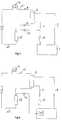
- FIG. 2shows one actual dialysis machine 1 with the upper monitoring level 2, the middle level 3, which is a blood pump 4 and an air detector 5 contains, and with a lower level 6, which the Has hydraulic part.
- the dialysis machine 1is connected to the dialyzer via a feed line 7 8 connected, from which a return line 9 to the dialysis machine 1 returns to a dialysis fluid circuit conclude.
- a Blood pump segment 12 of the arterial blood tubing 10is inserted into the blood pump 4 while the venous blood tubing 11 leads over the air detector 5.
- the blood tubingmust be prepared to prepare dialysis treatment 10 and 11 are flushed out and the extracorporeal Blood circulation must be vented and filled. For this It has so far been common for the free end of the arterial blood tubing 10 with the output of a saline containing bag 13 to connect.
- the blood pump 4promotes the saline solution through the arterial blood tubing 10, the dialyzer 8, the venous blood tubing 11 and the Air detector 5 to finally flush the rinsing liquid into one to drain open container 14.
- FIG. 1in which - as in 3 to 6- the components that with those of FIG. 2nd match, are identified by the same reference numerals. Their repetition is for reasons of clarity waived.
- the arterial Blood tubing 10by means of a disposable article 15 on the Connected to the place on the dialyzer 8 at which, according to FIG venous blood tubing 11 is connected.
- the blood pump segment 12 of the arterial blood tubing 10is by means of of a disposable article 16 with the venous blood tubing 11 connected.
- the venous blood tubing 11leads again the air detector 5 and is on by means of a disposable item 17 a sampling valve 18 connected.
- a Sterile filter 19arranged to ensure sterility the rinsing liquid further increased.
- dialysis fluidescapes the dialysis fluid circuit 7, 8, 9 into the arterial Hose line 10 and the venous hose line 11, from where it returned to the dialysis fluid circuit (at 18) is to to balance and other machine-side disturbances avoid.
- the arterial blood tubing 10 and the venous blood tubing 11 connected to the dialyzer 8 in the manner as described in connection with Figure 2 and at dialysis treatmentis the case.
- a three-way valve 20is arranged in line 9, the Connections 21 and 22 are assigned to line 9 while being Port 23 is normally open to the atmosphere.
- the blood pump segmentis not in the blood pump 4 inserted.
- FIG. 4Another embodiment is shown in FIG. 4.
- a valve 29in the form of a Hose clamp inserted.
- the blood pump 4is opposite to its normal direction of delivery (Direction arrow A) activated (e.g. by Change their direction of rotation), the valve 29 is closed and the valve 30 opened.
- Direction arrow Anormal direction of delivery
- the valve 29is closed and the valve 30 opened.
- the activity of the blood pumpcreates in the blood compartment a negative pressure of the dialyzer 8. This causes filtered Dialysis fluid into the blood compartment and the blood tube system over, so that this is filled in a short time.
- the pumped air and subsequent liquidare over the open valve 30 promoted in the dialysis fluid system.
- the mentioned switching of the valves 29, 30 and the conveying direction the blood pump 4can easily be automatically running program within the control program of the Dialysis machine can be effected, so that there is a significant Simplifies work.
- the patient side Connections of the blood tubesare for the purpose of filling and rinsing the extracorporeal blood circuit together connected.
- One branching off from the upper part of the venous drip chamberThe line is connected to a suction device 31, which serves in the entire extracorporeal conduit system, including the blood compartment of the dialyzer 8, one Generate negative pressure, so that filtered dialysis fluid passes into the blood compartment. With blood pump on 4 this fluid then circulates through the entire circuit. Air and excess liquid are removed from the branched off the upper part of the venous drip chamber.
- the suction device 31can be an external suction device, e.g. using what is often available in hospitals Vacuum line network, possibly with an intermediate one Liquid separator, or it can be designed as a pump be, the escaping liquid in a collecting vessel collected or drained into the dialysis fluid system can be.
- the suction of this pumpcan be used for the purpose described above by using a Line connection between the upper part of the venous drip chamber and the subsection mentioned.
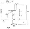
- FIG. 6ties in with the previous one Example, but offers additional functions.
- the upper part the venous drip chamber 28is via a line 32 into which a peristaltic pump 33 is inserted with the dialysis fluid system in connection.
- a Buffer vessel 34inserted, e.g. in the form of an elastic bag with a volume of typically about 20-50 ml.
- a valve 35inserted, preferably in the form of a Hose clamp valve.
- the patient's arterial and venous connectionsBlood tube connected together.
- the valve 35is open.
- the pump 33delivers in the direction A. This creates how in the previous example, a negative pressure in the blood tube system, so that filtered dialysis fluid through the membrane of the dialyzer 8 passes into the blood compartment. The removed Air and the excess liquid get over the pump 33 into the dialysis fluid system.
- the Dialysis membraneperiodically against the normal direction of filtration flushing out, i.e. Deposits that are on the blood side the membrane have accumulated to remove. It is known, that such deposits, the so-called secondary membrane form and consist of substances that make up the membrane cannot pass the effective diffusion resistance of the Enlarge the membrane and thereby the effectiveness of blood purification, especially with regard to the elimination of higher molecular weight Reduce pollutants.
- the dialysis fluid systemis rigid in volume, such as it with dialysis fluid systems with automatic balancing (e.g. according to DE-OS 28 38 414) is the case.
- the valve 35is always closed.
- the dialysis membrane Pump 33It runs to flush the dialysis membrane Pump 33 for a short time (a few seconds) with a relatively high delivery speed (on the order of 2-10 ml / s) towards A and transports liquid from the buffer vessel 34 in the dialysis fluid circuit. Because of the rigid volume Behavior of the dialysis fluid system increases the pressure in the Dialysate compartment of the dialyzer on the pressure in the blood compartment so that a corresponding amount of liquid counteracts passes into the blood in the normal direction of filtration and washed away the layers. In the following The pump supports the operating phase with normal filtration direction 33 slowly in direction B and thus fills the buffer vessel 34 back on. After a certain time the pump will be back in Direction A started to flush the next time Initiate dialyzer membrane. The frequency of flushing the dialyzer membrane can be changed as required. The Incidentally, the total filtrate balance is from the described processes not influenced, but is, according to the way it works of a balancing dialysis fluid system from which set ultrafiltration rate
- the arrangement shown in FIG. 6can also be used for this to expand hemodialysis to hemodiafiltration i.e. hemodialysis with a significantly increased ultrafiltration rate to be carried out with substitution of the largest Part of the amount of liquid withdrawn via the dialyzer Supply of an appropriate amount of a physiologically adjusted Solution in the bloodstream.
- the valve 35is opened and the pump 33 operated with the conveying direction B.
- the conveyor speedis typically set to 1/3 - 1/5 of the conveying speed of the Blood pump 4 set.
- Dialysis fluid systembehaves rigidly in volume (automatically accounting system) arises from the activity of the pump 33 an additional negative pressure in the dialysate compartment of the dialyzer, the one corresponding to the delivery speed of the pump 33 Amount of filtrate from the blood compartment into the dialysate compartment lets pass.
- the overall filtrate balancewill also in this case not affected by the processes described, but will, depending on how a balancing dialysis fluid system, from the set Ultrafiltration rate determined.
- the functions describedcan be combined will.
- the applicationis a particularly useful combination the periodic flushing of the dialyzer membrane at the Hemodiafiltration, as described or another Process is carried out because precisely at the high filtration speeds, those used in hemodiafiltration arrive, the formation of an inhibiting the exchange of substances Secondary membrane is particularly pronounced.
Landscapes
- Health & Medical Sciences (AREA)
- Heart & Thoracic Surgery (AREA)
- Vascular Medicine (AREA)
- Life Sciences & Earth Sciences (AREA)
- Engineering & Computer Science (AREA)
- Anesthesiology (AREA)
- Biomedical Technology (AREA)
- Hematology (AREA)
- Animal Behavior & Ethology (AREA)
- General Health & Medical Sciences (AREA)
- Public Health (AREA)
- Veterinary Medicine (AREA)
- Cardiology (AREA)
- Urology & Nephrology (AREA)
- Emergency Medicine (AREA)
- External Artificial Organs (AREA)
Abstract
Description
Translated fromGermanDie Erfindung betrifft ein Verfahren zum Spülen und Befülleneines extrakorporalen Blutkreislaufs von Dialysemaschinen,insbesondere von Blutschlauchleitungen und Dialysatoren.The invention relates to a method for rinsing and fillingan extracorporeal blood circuit of dialysis machines,especially of blood tubing and dialyzers.
Die Erfindung betrifft ferner die Anwendung des Verfahrens inVerbindung mit einer Hämodiafiltration.The invention further relates to the application of the method inConnection with hemodiafiltration.
Als arterielle und venöse Blutschlauchleitung eines extrakorporalenBlutkreislaufs werden heutzutage üblicherweise sterilverpackte Einmalartikel verwendet, die vor einer Behandlunggespült, entlüftet und befüllt werden müssen. Dies geschiehtbisher mittels physiologischer Kochsalzlösungen, die mittels dermaschineneigenen Blutpumpe durch das Schlauchsystem und denDialysator gefördert werden, um den extrakorporalen Blutkreislaufvon Verunreinigungen freizuspülen und unter vollständigerEntlüftung zu befüllen.As an arterial and venous blood tubing of an extracorporealBlood circulation usually becomes sterile these dayspackaged disposable items used before treatmentmust be flushed, vented and filled. this happenshitherto using physiological saline solutions using themachine's own blood pump through the hose system and theDialyzers are promoted to the extracorporeal bloodstreamRinse free of contaminants and under completeTo fill the vent.
Die Verwendung der Kochsalzspülflüssigkeit hat den Nachteil, daßsie mit erheblichen Kosten verbunden ist.The use of the saline rinsing liquid has the disadvantage thatit is associated with considerable costs.
Aus der FR-A-2175945 ist ein Verfahren bekannt, bei dem voneiner Dialysemaschine erzeugte Dialysierflüssigkeit durch einenextrakorporalen Blutkreislauf gefördert wird. In dieser Druckschriftwird vorgeschlagen, zur Spülung des extrakorporalenBlutkreislaufs nach Beendigung einer Dialyse die beiden Schläuchedes extrakorporalen Blutkreislaufs mit den Leitungen desDialysierflüssigkeitskreislaufs zu verbinden.From FR-A-2175945 a method is known in whicha dialysis machine generated by a dialysis machineextracorporeal blood circulation is promoted. In this publicationis proposed to flush the extracorporealBlood circulation after completing dialysis the two tubesof the extracorporeal blood circuit with the lines of theTo connect the dialysis fluid circuit.
Der vorliegenden Erfindung liegt die Aufgabe zugrunde, einVerfahren zur Spülung, Entlüftung und Befüllung eines extrakorporalenBlutkreislaufs von Dialysemaschinen anzugeben, das mitgeringeren Kosten verbunden ist. Außerdem soll ein Anordnungangegeben werden, mit der dieses Verfahren ausführbar ist.The present invention is based on the objectProcess for flushing, venting and filling an extracorporealSpecify blood circulation of dialysis machines that withlower costs. An arrangement is also intendedwith which this procedure can be carried out.
Diese Aufgabe wird erfindungsgemäß durch die im Kennzeichen desAnspruchs 1 angegebenen Merkmale gelöst.Vorteilhafte Weiterbildungender Erfindung sind in den abhängigen Ansprüchen gekennzeichnet.This object is achieved by the in the characteristic ofFeatures specified 1 solved. Advantageous further developmentsthe invention are characterized in the dependent claims.
Nach dem erfindungsgemäßen Verfahren wird die von der Dialysemaschineerzeugte bzw. aufbereitete Dialysierflüssigkeit zumZwecke des Spülens, Entlüftens und Befüllens durch den bzw. inden extrakorporalen Blutkreislauf gefördert. Hierdurch entfälltdas bisherige Erfordernis, eine in einem Beutel abgefüllteKochsalzlösung zu diesem Zweck bereit zu stellen, der zudem voneiner Bedienungsperson an die arterielle Blutschlauchleitunganzuschließen war. Es entfällt damit ferner das Erfordernis, zudem genannten Zweck Kochsalzlösungen in größeren Mengen bereitzu halten und die geleerten Beutel zu entsorgen.According to the inventive method, that of the dialysis machinegenerated or prepared dialysis fluid forPurpose of flushing, venting and filling by thepromoted the extracorporeal blood circulation. This eliminatesthe previous requirement, one filled in a bagTo provide saline for this purpose, which is also froman operator to the arterial blood tubingwas to be connected. It also eliminates the need toSaline solutions are available in larger quantities for this purposehold and dispose of the emptied bags.
Gemäß der Erfindung wird die Dialysierflüssigkeit blutseitig desDialysators abgenommen, wobei sie beim Durchtritt durch dieMembran filtriert wird. Hiermit ist die Keimfreiheit der Spül- undBefüllflüssigkeit zuverlässig gewährleistet.According to the invention, the dialysis fluid is the blood side of theDialysators removed, being passed through theMembrane is filtered. This is the sterility of the flushing andFilling liquid guaranteed reliably.
Nach einem weiteren Vorschlag der Erfindung kann die dem Dialysatorentnommene Dialysierflüssigkeit von der maschineneigenenBlutpumpe durch den extrakorporalen Blutkreislauf gepumpt werden,was nachfolgend in näheren Einzelheiten erläutert wird. Beidieser Ausgestaltung der Erfindung wird die Saugseite der arteriellenBlutschlauchleitung vorzugsweise mittels eines Einmalartikelsan dem Dialysator konnektiert, vorzugsweise an derStelle, an der bei der Dialysebehandlung die venöse Blutschlauchleitungangeschlossen wird. Das Blutpumpensegment derarteriellen Blutschlauchleitung wird in die maschineneigeneBlutpumpe, vorzugsweise eine Rollerpumpe, eingelegt, und dasandere, freie Ende der arteriellen Blutschlauchleitung wirdvorzugsweise über einen weiteren Einmalartikel mit dem Einlaufder venösen Blutschlauchleitung konnektiert. Die venöse Blutschlauchleitungdurchläuft auf übliche Weise einen Luftdetektor. Das andere Ende der venösenBlutschlauchleitung wird stromabwärts des Dialysators an denDialsysierflüssigkeitskreislauf angeschlossen, vorzugsweisemittels eines weiteren Einmalartikels an ein Probeentnahmeventildieses Dialysierflüssigkeitskreislaufs.According to a further proposal of the invention, the dialyzerwithdrawn dialysis fluid from the machine's ownBlood pump can be pumped through the extracorporeal blood circuit,which is explained in more detail below. Atthis embodiment of the invention is the suction side of the arterialBlood tubing, preferably using a disposable itemconnected to the dialyzer, preferably to thePlace where the venous blood tubing is used during dialysis treatmentis connected. The blood pump segment of thearterial blood tubing gets into the machine's ownBlood pump, preferably a roller pump, inserted, and thatother, free end of the arterial blood tubingpreferably via another disposable item with the enemaconnected to the venous blood tubing. The venous blood tubinggoes throughan air detector in the usual way. The other end of the venousBlood tubing is connected to the downstream of the dialyzerDialysis fluid circuit connected, preferablyby means of another disposable item to a sampling valvethis dialysis fluid circuit.
Wenn die Blutpumpe in Betrieb gesetzt wird, wird Dialysierflüssigkeitüber die semipermeable Membran des Dialysators in dieBlutschlauchleitungen gezogen. Dabei gelangt nur sterile undkeimfreie Spülflüssigkeit in den extrakorporalen Blutkreislauf.Die Spülflüssigkeit und die in dem extrakorporalen Kreislaufzuvor befindliche Luft werden stromabwärts des Dialysators inden Dialysierflüssigkeitskreislauf der Dialysemaschine eingeführt,womit bilanz- und sonstige maschinenseitigen Störungenvermieden sind.When the blood pump is started, dialysis fluid becomesover the semipermeable membrane of the dialyzer into theBlood tubing pulled. Only sterile andaseptic irrigation fluid in the extracorporeal bloodstream.The irrigation fluid and that in the extracorporeal circuitpreviously located air is in downstream of the dialyzerintroduced the dialysis fluid circuit of the dialysis machine,with what balance and other machine-side malfunctionsare avoided.
Nach einem alternativen Vorschlag der Erfindung wird die Dialysierflüssigkeitzum Zwecke der Spülung, Entlüftung und Befüllungdes extrakorporalen Blutkreislaufs nicht mittels der maschineneigenenBlutpumpe, sondern von einer Pumpe des Dialysierflüssigkeitskreislaufsdurch die bzw. in die Blutschlauchleitungen gepumpt.Hierbei kann dieser Vorgang durch das maschinenspezifischeFüllprogramm hervorgerufen werden.According to an alternative proposal of the invention, the dialysis fluidfor the purpose of flushing, venting and fillingof the extracorporeal blood circulation not by means of the machine's ownBlood pump, but from a pump of the dialysis fluid circuitpumped through or into the blood tubing.This process can be done by the machine-specificFilling program can be caused.
Im einzelnen ist bei dieser bevorzugten Ausführungsform deserfindungsgemäßen Verfahrens vorgesehen, daß die arterielle unddie venöse Blutschlauchleitung in der Weise an dem Dialysatorkonnektiert werden, wie dies bei einer Dialysebehandlung derFall ist. In dem Dialysierflüssigkeitskreislauf ist stromabwärtsdes Dialysators ein Dreiwege-Ventil mit 2/2 Wegen angeordnet,mit dem der Dialysierflüssigkeitskreislauf ganz oder teilweiseverschließbar ist bzw. unterbrochen werden kann. Das dritteVentil dieses Dreiwege-Hahns, der vorzugsweise mechanisch einfachzu verstellen ist, liegt nicht im Dialysierflüssigkeitskreislauf und kann eine zur Atmosphäre hin offene Verbindungschaffen.In particular, in this preferred embodiment of theinventive method provided that the arterial andthe venous blood tubing in the manner on the dialyzerbe connected, as is the case with a dialysis treatment of theCase is. In the dialysis fluid circuit is downstreama three-way valve with 2/2 ways is arranged on the dialyzer,with which the dialysis fluid circuit is wholly or partiallycan be closed or interrupted. The thirdValve of this three-way valve, which is preferably mechanically simpleis not in the dialysis fluid circuitand can be a connection open to the atmospherecreate.
Zum Spülen und Befüllen des extrakorporlane Blutkreislaufs wirdder Dreiwege-Hahn so geschaltet, daß der Dialysierflüssigkeitskreislaufzur Atmosphäre hin geöffnet ist, während die von demDialysator wegführende Leitung ganz oder teilweise verschlossenist. Es wird betont, daß eine Zwischenstellung des Dreiwegehahnseingestellt werden kann, in der noch ein Teil der Dialysierflüssigkeitüber die Ventilanordnung abfließen kann, was weiterunten noch erläutert wird.For flushing and filling the extracorporeal blood circulationthe three-way valve is switched so that the dialysis fluid circuitis open to the atmosphere, while that of theDialyzer leading line completely or partially closedis. It is emphasized that an intermediate position of the three-way valvecan be set in which still part of the dialysis fluidcan drain through the valve assembly, what furtherwill be explained below.
Wenn der Dialysierflüssigkeitskreislauf durch entsprechendeSchaltung des Dreiwegehahns zur Atmosphäre hin geöffnet ist,kann die maschineneigene Sensorik die Luft erkennen, die überden zugeordneten Anschluß ins Maschineninnere gelangt, und dasmaschinenspezifische Füllprogramm auslösen. Die dabei von derMaschine kommende Dialysierflüssigkeit wird über den Dialysatorin die beiden angeschlossenen Blutschlauchleitungen gedrückt, dader Dreiwegehahn den Dialysierflüssigkeitskreislauf ganz oderteilweise unterbrochen hat. Somit werden die Blutschlauchleitungengespült, entlüftet und mit der Dialysierflüssigkeit befüllt.If the dialysis fluid circuit is replaced by appropriateCircuit of the three-way valve is open to the atmosphere,the machine's own sensors can detect the air thatthe assigned connection gets inside the machine, and thatTrigger machine-specific filling program. The from theDialysing fluid coming into the machine is fed through the dialyzerpressed into the two connected blood tubing lines becausethe three-way tap completely orpartially interrupted. Thus, the blood tubingrinsed, vented and filled with the dialysis fluid.
Die patientenseitigen Anschlüsse werden nach einem weiterenVorschlag der Erfindung beispielsweise an einen leeren Beutelkonnektiert. In diesem Fall kann es sich empfehlen, den Dreiwegehahnauf eine Zwischenstellung zu schalten, um den Dialysierflüssigkeitskreislaufnur teilweise zu verschließen, damit derBeutel nicht mit einer zu großen Spülflüssigkeitsmenge gefülltbzw. nicht mit zu großem Druck belastet wird, der ihn platzenlassen könnte.The patient-side connections are made after anotherProposal of the invention for example to an empty bagconnected. In this case it may be advisable to use the three-way valveto switch to an intermediate position to the dialysis fluid circuitonly partially closed so that theBags are not filled with too much rinsing liquidor is not subjected to excessive pressure that will burst itcould leave.
Nach einem alternativen Vorschlag der Erfindung können diepatientenseitigen Anschlüsse der beiden Blutschlauchleitungen anden dritten, nicht im Dialysierflüssigkeitskreislauf liegendenAnschluß des Dreiwegebahns konnektiert werden, und zwar vorzugsweisemittels eines geeigneten Einmalartikels. Eine weitereMöglichkeit besteht darin, daß die freien Enden der Blutschlauchleitungenso angeordnet werden, daß sie in ein offenesGefäß einmünden.According to an alternative proposal of the invention, thepatient-side connections of the two blood tubing linesthe third, not in the dialysis fluid circuitConnection of the three-way track can be connected, preferablyusing a suitable disposable item. AnotherPossibility is that the free ends of the blood tubingbe arranged so that they are in an openOpen the vessel.
Bei dieser letztgenannten Ausführungsform des erfindungsgemäßenVerfahrens bzw. der erfindungsgemäßen Anordnung wird das arteriellePumpsegment nicht in die Blutpumpe eingelegt, da dieBefüllung der arteriellen Blutschlauchleitung in umgekehrterRichtung erfolgt.In this latter embodiment of the inventionThe method or the arrangement according to the invention is the arterialPump segment is not inserted into the blood pump because theFilling the arterial blood tubing in reverseDirection.
Ein Vorteil der vorstehend beschriebenen zweiten Variante bestehtdarin, daß dialysatorseitig keine sterilen Einmalartikelbenötigt werden und daß die arterielle und die venöse Blutschlauchleitungwie gewohnt konnektiert werden und unverändertbleiben.There is an advantage of the second variant described abovein that there are no sterile disposable items on the dialyzer sideare needed and that the arterial and venous blood tubingbe connected as usual and unchangedstay.
Die Spül- und Befüllvorgang muß nicht notwendigerweise durch dasmaschinenspezifische Füllprogramm ausgelöst werden, welches aufins Maschineninnere gelangte Luft anspricht.The rinsing and filling process does not necessarily have to be done by themachine-specific filling program, which is triggeredair entering the machine responds.
Eine dritte Variante des erfindungsgemäßen Verfahrens sieht vor,daß nach dem Konnektieren der arteriellen und venösen Blutschlauchleitungam Dialysator die Patientenanschlüsse dieserbeiden Leitungen miteinander verbunden werden, um eine durchgehendeFlüssigkeitsleitung zu bilden, daß der Strömungswegzwischen dem venösen Blutanschluß des Dialysators und der zurEntlüftung vorzugsweise vorgesehenen venösen Tropfkammer gesperrtwird, daß die Blutpumpe entgegen ihrer normalen Förderrichtungin Betrieb gesetzt wird, und daß die aus dem Blutschlauchsystemverdrängte Luft und überschüssige Flüssigkeit durch eine mit dem oberen Teil der venösen Tropfkammer verbundeneLeitung abgeleitet wird. Dabei kann vorgesehen sein, daß dieverdrängte Luft und die überschüssige Flüssigkeit in das Dialysierflüssigkeitsystemdes Dialysegerätes abgeführt werden.A third variant of the method according to the invention providesthat after connecting the arterial and venous blood tubingthe patient connections on the dialyzertwo lines are connected together to form a continuousLiquid line to form that flow pathbetween the venous blood connection of the dialyzer and theVenting preferably provided for venous drip chamber blockedis that the blood pump against its normal direction of deliveryis put into operation, and that from the blood tube systemdisplaced air and excess liquidthrough one connected to the upper part of the venous drip chamberLine is derived. It can be provided that thedisplaced air and the excess fluid into the dialysis fluid systemof the dialysis machine.
Dieses erfindungsgemäße Verfahren kann dadurch weiter ausgestaltetwerden, daß intermittierend die normalen Strömungsverhältnissedes extrakorporalen Blutkreislaufs hergestellt werden,d.h. Öffnen des Strömungsweges zwischen dem venösen Blutanschlußdes Dialysators und der venösen Tropfkammer und Inbetriebsetzender Blutpumpe in ihrer normalen Förderrichtung, wobei die mitdem oberen Teil der venösen Tropfkammer verbundene Leitungverschlossen ist.This method according to the invention can thereby be further developedbe that intermittent the normal flow conditionsof the extracorporeal blood circulationi.e. Open the flow path between the venous blood connectionof the dialyzer and the venous drip chamber and start-upthe blood pump in its normal delivery direction, with theline connected to the upper part of the venous drip chamberis closed.
Das Umschalten der Ventile und der Förderrichtung der Blutpumpekann über ein automatisch ablaufendes Programm im Rahmen desSteuerungsprogramms des Dialysegerätes bewirkt werden.Switching the valves and the direction of delivery of the blood pumpcan be run via an automatically running program within theControl program of the dialysis machine can be effected.
Bei einer weiteren Variante des erfindungsgemäßen Verfahrenswerden wie bei der dritten Ausführungsform der arterielle undder venöse Patientenanschluß der Blutschlauchleitungen zurSchaffung einer durchgehenden Flüssigkeitsleitung miteinanderverbunden, und eine an den oberen Teil der venösen Tropfkammerangeschlossene Leitung wird mit einer Saugvorrichtung versehenbzw. verbunden. Hierbei kann als Saugvorrichtung das Entgasungssystemdes Dialysegerätes verwendet werden, wobei alternativeine Pumpe angeordnet sein kann, deren abfördernde Leitung mitdem Dialysierflüssigkeitssystem verbunden sein kann.In a further variant of the method according to the inventionlike the third embodiment, the arterial andthe venous patient connection of the blood tubing toCreation of a continuous liquid line with each otherconnected, and one to the top of the venous drip chamberconnected line is provided with a suction deviceor connected. Here, the degassing system can be used as a suction deviceof the dialysis machine can be used, alternativelya pump can be arranged, the discharge line withcan be connected to the dialysis fluid system.
In weiterer Ausgestaltung des erfindungsgemäßen Verfahrens kannvorgesehen sein, daß in der Dialysatkammer des Dialysators invorgegebenen Zeitabständen ein erhöhter Druck erzeugt wird, derden Druck in der Blutkammer des Dialysators übersteigt und eineFiltration von Dialysierflüssigkeit in das Blut bewirkt. Diesernach dem Anschließen eines Patienten und dem Beginn der eigentlichen Behandlung erfolgende Vorgang dient dazu, die Dialysemembranentgegen der normalen Filtrationsrichtung periodischfreizuspülen, d. h. Ablagerungen, die sich auf der Blutseite derMembran angesammelt haben, zu entfernen.In a further embodiment of the method according to the inventionbe provided that in the dialysate chamber of the dialyzerpredetermined time intervals an increased pressure is generated, thethe pressure in the blood chamber of the dialyzer exceeds oneFiltration of dialysis fluid into the blood causes. Thisafter connecting a patient and starting the actual oneTreatment process is used to remove the dialysis membraneperiodically against the normal direction of filtrationto flush, d. H. Deposits that are on the blood side of theHave accumulated to remove the membrane.
Vorzugsweise wird bei diesem Verfahren ein volumenstarr wirkendesDialysierflüssigkeitssystem verwendet, wodurch die Möglichkeitgeschaffen ist, daß eine periodische Druckerhöhung undDruckabsenkung mit der Pumpe bewirkt wird, die abwechselndzusätzliche Flüssigkeit in das Dialysierflüssigkeitssystemeinführt bzw. dem Dialysierflüssigkeitssystem Flüssigkeit entzieht,was in näheren Einzelheiten weiter unten noch beschriebenwird.In this method, it is preferred that the volume is fixedDialysis fluid system used, giving the possibilityis created that a periodic pressure increase andPressure drop with the pump is effected alternatelyadditional fluid into the dialysis fluid systemintroduces or withdraws fluid from the dialysis fluid system,which is described in more detail belowbecomes.
Erfindungsgemäß kann dieses Verfahren in Verbindung mit einerHämodiafiltration angewendet werden.According to the invention, this method can be used in conjunction with aHemodiafiltration can be applied.
Nach einem zusätzlichen Vorschlag der Erfindung ist vorgesehen,daß ein Sterilfilter stromaufwärts des Dialysators in dem Dialysierflüssigkeitskreislaufangeordnet wird, um die Sicherheit inBezug auf die erforderliche Keimfreiheit zusätzlich zu erhöhen.According to an additional proposal of the invention,that a sterile filter upstream of the dialyzer in the dialysis fluid circuitis arranged to security inIn addition to the required sterility to increase.
Nach einem weiteren Gesichtspunkt der Erfindung wird vorgeschlagen,daß die als Spülflüssigkeit verwendete Dialysierflüssigkeitnach Beendigung einer Dialysebehandlung zur Freispülung desextrakorporalen Blutkreislaufes verwendet wird, wozu es zweckmäßigist, diese Flüssigkeit beim Spülvorgang in einen Beutelabzuführen. Das Freispülen ist notwendig, um nach der Dialysebehandlungdas Blut vollständig zum Patienten zurückzuführen, wasbisher ebenfalls mit Hilfe einer Kochsalzlösung geschieht.According to a further aspect of the invention, it is proposed thatthat the dialysis fluid used as the rinsing fluidafter completing dialysis treatment to flush out theextracorporeal blood circulation is used for what it is appropriateis this liquid in a bag during the rinsing processdissipate. The flushing is necessary to after the dialysis treatmentthe blood completely returned to the patient whatpreviously also done with the help of a saline solution.
Ein weiterer erfindungsgemäßer Vorschlag geht dahin, die extrakorporalenKomponenten so zu reinigen, daß sie wiederverwendbarsind. Hierzu kann die Anordnung so getroffen werden, wiesie weiter oben im Zusammenhang mit der ersten Ausführungsformdes erfindungsgemäßen Verfahrens beschrieben ist. Bei einemdialysemaschinenspezifischen Reinigungsprogramm wird durch dieFörderung der Blutpumpe Reinigungsflüssigkeit über die semipermeableMembran des Dialysators in den extrakorporalen Kreislaufgezogen, wodurch dieser entsprechend gereinigt wird.Another proposal according to the invention goes there, the extracorporealClean components so that they are reusableare. For this purpose, the arrangement can be made assee above in connection with the first embodimentof the method according to the invention is described. At adialysis machine specific cleaning program is through thePromote the blood pump cleaning fluid via the semipermeableMembrane of the dialyzer in the extracorporeal circuitpulled, which is cleaned accordingly.
Selbstverständlich liegt es im Rahmen der Erfindung, die extrakorporalenKomponenten weiterhin als Einmalartikel einzusetzen.Of course, it is within the scope of the invention, the extracorporealContinue to use components as single-use items.
Weitere Merkmale, Vorteile und Einzelheiten der Erfindung ergebensich aus der nachfolgenden Beschreibung einiger bevorzugterAusführungsformen sowie anhand der Zeichnung. Dabei zeigen aufrein schematische Weise:
- Fig. 1
- eine erste Ausführungsform zur Ausführung des erfindungsgemäßenVerfahrens;
- Fig. 2
- eine herkömmliche Anordnung;
- Fig. 3
- eine zweite Ausführungsform zur Ausführung des erfindungsgemäßenVerfahrens;
- Fig. 4
- eine dritte Ausführungsform zur Ausführung des erfindungsgemäßenVerfahrens;
- Fig. 5
- eine vierte Ausführungsform zur Ausführung des erfindungsgemäßenVerfahrens und
- Fig. 6
- eine fünfte Ausführungsform zur Ausführung des erfindungsgemäßenVerfahrens.
- Fig. 1
- a first embodiment for carrying out the method according to the invention;
- Fig. 2
- a conventional arrangement;
- Fig. 3
- a second embodiment for performing the method according to the invention;
- Fig. 4
- a third embodiment for performing the method according to the invention;
- Fig. 5
- a fourth embodiment for performing the method according to the invention and
- Fig. 6
- a fifth embodiment for carrying out the method according to the invention.
Es wird zunächst auf Fig. 2 Bezug genommen, um das bisher üblicheVerfahren zum Spülen, Entlüften und Befüllen eines extrakorporalenBlutkreislaufs zu erläutern. Die Fig. zeigt eineeigentliche Dialysemaschine 1 mit der oberen Überwachungsebene2, der mittleren Ebene 3, die eine Blutpumpe 4 und einen Luftdetektor 5 enthält, und mit einer unteren Ebene 6, die denHydraulikteil aufweist.Reference is first made to FIG. 2 to describe what has been customary up to nowProcess for flushing, venting and filling an extracorporealTo explain blood circulation. The figure shows oneactual dialysis machine 1 with the
Die Dialysemaschine 1 ist über eine Zuleitung 7 mit dem Dialysator8 verbunden, von dem eine Rückleitung 9 zur Dialysemaschine1 zurückführt, um einen Dialysierflüssigkeitskreislauf zuschließen.The dialysis machine 1 is connected to the dialyzer via a
Zum Zwecke einer Dialysebehandlung werden eine arterielleBlutschlauchleitung 10 und eine venöse Blutschlauchleitung 11 anden dargestellten Stellen an dem Dialysator 8 konnektiert. EinBlutpumpensegment 12 der arteriellen Blutschlauchleitung 10 wirdin die Blutpumpe 4 eingelegt, während die venöse Blutschlauchleitung11 über den Luftdetektor 5 führt.For the purpose of dialysis treatment, an
Zur Vorbereitung einer Dialysebehandlung müssen die Blutschlauchleitungen10 und 11 freigespült werden und der extrakorporaleBlutkreislauf muß entlüftet und befüllt werden. Hierzuist es bisher üblich, das freie Ende der arteriellen Blutschlauchleitung10 mit dem Ausgang eines eine Kochsalzlösungenthaltenden Beutels 13 zu verbinden. Die Blutpumpe 4 fördertdie Kochsalzlösung durch die arterielle Blutschlauchleitung 10,den Dialysator 8, die venöse Blutschlauchleitung 11 und denLuftdetektor 5, um schließlich die Spülflüssigkeit in einenoffenen Behälter 14 abzuführen.The blood tubing must be prepared to prepare
Es wird nun auf Fig. 1 Bezug genommen, in der -ebenso wie inFig. 3 bis 6- die Bauteile, die mit denjenigen gemäß Fig. 2übereinstimmen, mit denselben Bezugszeichen gekennzeichnet sind.Auf ihre Wiederholung wird aus Gründen der Übersichtlichkeitverzichtet.Reference is now made to Fig. 1, in which - as in3 to 6- the components that with those of FIG. 2ndmatch, are identified by the same reference numerals.Their repetition is for reasons of claritywaived.
Bei dieser Ausführungsform der Erfindung wird die arterielleBlutschlauchleitung 10 mittels eines Einmalartikels 15 an derStelle an dem Dialysator 8 konnektiert, an der gemäß Fig. 2 dievenöse Blutschlauchleitung 11 angeschlossen ist. Das Blutpumpensegment12 der arteriellen Blutschlauchleitung 10 ist mittelseines Einmalartikels 16 mit der venösen Blutschlauchleitung 11verbunden. Die venöse Blutschlauchleitung 11 führt wiederum überden Luftdetektor 5 und ist mittels eines Einmalartikels 17 anein Probeentnahmeventil 18 angeschlossen.In this embodiment of the invention, the
In der Leitung 7 des Dialysierflüssigkeitskreislaufs ist einSterilfilter 19 angeordnet, der die Sicherheit der Keimfreiheitder Spülflüssigkeit weiter erhöht.In
Durch Förderung der Blutpumpe 4 gelangt Dialysierflüssigkeit ausdem Dialysierflüssigkeitskreislauf 7, 8, 9 in die arterielleSchlauchleitung 10 und die venöse Schlauchleitung 11, von wo siein den Dialysierflüssigkeitskreislauf (bei 18) zurückgegebenwird, um bilanz- und sonstige maschinenseitigen Störungen zuvermeiden.By promoting the
Bei der erfindungsgemäßen Ausführungsform gemäß Fig. 3 werdendie arterielle Blutschlauchleitung 10 und die venöse Blutschlauchleitung11 in der Weise an dem Dialysator 8 konnektiert,wie dies im Zusammenhang mit der Figur 2 beschrieben und beieiner Dialysebehandlung der Fall ist. Bei dieser Ausführungsformist ein Dreiwegehahn 20 in der Leitung 9 angeordnet, dessenAnschlüsse 21 und 22 der Leitung 9 zugeordnet sind, während seinAnschluß 23 normalerweise zur Atmosphäre hin offen ist.3 in the embodiment according to the inventionthe
Während einer Dialysebehandlung besteht eine Verbindung von 21nach 22, während -wie gesagt- Anschluß 23 zur Atmosphäre hinoffen ist. Zum Spülen des extrakorporalen Blutkreislaufs wirddie Ventilanordnung 20 umgeschaltet auf Durchgang 22, 23, wobeiauch eine Zwischenstellung schaltbar ist, in der ein eingeschränkter Durchgang 21, 22 bestehen bleibt. Von der Dialysemaschine1 kommende Dialysierflüssigkeit wird über den Dialysator8 in die Blutschlauchleitungen 10, 11 gedrückt, wobei diesedurchgespült werden. Die Spülflüssigkeit kann entweder überLeitungen 24 in einen Beutel 25, über Leitungen 26 in das offeneGefäß 14 abgeführt oder über Leitungen 27 dem Anschluß 23 desDreiwegeventils 20 zugeführt wreden, von wo die Flüssigkeit inden Dialysierflüssigkeitskreislauf bzw. dessen Leitung 9 gelangt.There is a connection of 21 during dialysis treatmentafter 22, while - as I said -
Bei dieser Ausführungsform ist das Blutpumpensegment nicht indie Blutpumpe 4 eingelegt.In this embodiment, the blood pump segment is not inthe
Ein weiteres Ausführungsbeispiel ist in Fig. 4 gezeigt. BeimFüll- und Spülvorgang sind die patientenseitigen Anschlüsse desareriellen und des venösen Blutschlauches 10, 11 miteinanderverbunden. In die venöse Blutleitung 11 zwischen dem Dialysator8 und der venösen Tropfkammer 28 ist ein Ventil 29 in Form einerSchlauchklemme eingefügt. Vom oberen Teil der venösen Tropfkammer28 zweigt eine ebenfalls mit einem Ventil 30 ausgestatteteLeitung ab, die mit einem Auffanggefäß oder, wie in Fig. 4dargestellt, mit dem Dialysierflüssigkeitssystem verbunden ist.Another embodiment is shown in FIG. 4. At theFilling and rinsing are the patient connections of thearerial and the
Zum Zwecke des Füllens und Spülens des extrakorporalen Blutkreislaufeswird die Blutpumpe 4 entgegen ihrer normalen Förderrichtung(Richtungspfeil A) in Tätigkeit gesetzt (z.B. durchÄndern ihrer Drehrichtung), das Ventil 29 wird geschlossen unddas Ventil 30 geöffnet.For the purpose of filling and flushing the extracorporeal blood circuitthe
Durch die Tätigkeit der Blutpumpe entsteht im Blutkompartimentdes Dialysators 8 ein Unterdruck. Dadurch tritt filtrierteDialysierflüssigkeit in das Blutkompartiment und das Blutschlauchsystemüber, so daß dieses in kurzer Zeit gefüllt wird.Die abgepumpte Luft und nachfolgende Flüssigkeit werden über dasgeöffnete Ventil 30 in das Dialysierflüssigkeitssystem gefördert.The activity of the blood pump creates in the blood compartmenta negative pressure of the
Dieses Verfahren kann zur Intensivierung des Spülvorgangs nochdadurch ergänzt werden, daß zwischenzeitlich mehrfach das Ventil29 geöffnet wird (bei gleichzeitigem oder zeitlich versetztemSchließen des Ventils 30) und bei Bedarf zusätzlich die Blutpumpein ihrer normalen Förderrichtung (entgegen dem RichtungspfeilA) arbeitet.This procedure can still intensify the rinsing processare supplemented by the fact that the valve has been used
Die genannten Umschaltungen der Ventile 29, 30 und der Förderrichtungder Blutpumpe 4 können ohne weiteres über ein automatischablaufendes Programm im Rahmen des Steuerungsprogramms desDialysegerätes bewirkt werden, so daß sich eine erheblicheArbeitsvereinfachung erreichen läßt.The mentioned switching of the
Fig. 5 zeigt ein weiteres Ausführungsbeispiel. Die patientenseitigenAnschlüsse der Blutschläuche sind zum Zwecke des Füllensund Spülens des extrakorporalen Blutkreislaufes miteinanderverbunden. Eine vom oberen Teil der venösen Tropfkammer abzweigendeLeitung steht mit einer Saugvorrichtung 31 in Verbindung,die dazu dient, im gesamten extrakorporalen Leitungssystem,einschließlich des Blutkompartiments des Dialysators 8, einenUnterdruck zu erzeugen, so daß filtrierte Dialysierflüssigkeitin das Blutkompartiment übertritt. Bei eingeschalteter Blutpumpe4 zirkuliert diese Flüssigkeit dann durch den gesamten Kreislauf.Luft und überschüssige Flüssigkeit werden über die vomoberen Teil der venösen Tropfkammer abzweigende Leitung abgeführt.5 shows a further exemplary embodiment. The patient sideConnections of the blood tubes are for the purpose of fillingand rinsing the extracorporeal blood circuit togetherconnected. One branching off from the upper part of the venous drip chamberThe line is connected to a
Die Saugvorrichtung 31 kann eine externe Saugvorrichtung sein,z.B. unter Benutzung des in Krankenhäusern häufig verfügbarenVakuum-Leitungsnetzes, ggf. mit einem zwischengeschaltetenFlüssigkeitsabscheider, oder sie kann als Pumpe ausgebildetsein, wobei die austretende Flüssigkeit in einem Auffanggefäßgesammelt oder in das Dialysierflüssigkeitssystem abgeleitetwerden kann. Eine besonders einfache und damit vorteilhafteAnordnung ergibt sich, wenn als Saugvorrichtung das Entgasungssystem des Dialysegerätes mitbenutzt wird. Dabei handelt es sichbei den meisten Dialysegeräten um eine Pumpe, die in einemTeilabschnitt der stromabwärts von ihr liegenden Fließstreckeeinen starken Unterdruck erzeugt, um überschüssig gelöstes Gaszur Ausscheidung zu bringen. Die Saugtätigkeit dieser Pumpe kannfür den oben beschriebenen Zweck genutzt werden, indem man eineLeitungsverbindung zwischen dem oberen Teil der venösen Tropfkammerund dem genannten Teilabschnitt herstellt.The
Das Ausführungsbeispiel nach Fig. 6 knüpft an das vorhergehendeBeispiel an, bietet aber zusätzliche Funktionen. Der obere Teilder venösen Tropfkammer 28 steht über eine Leitung 32, in dieeine Schlauchpumpe 33 eingefügt ist, mit dem Dialysierflüssigkeitssystemin Verbindung. In den Leitungsabschnitt zwischen dervenösen Tropfkammer 28 und dieser Pumpe 33 ist außerdem einPuffergefäß 34 eingefügt, z.B. in Form eines elastischen Beutelsmit einem Volumen von typischerweise etwa 20-50 ml. Außerdem istin den Leitungsabschnitt zwischen der Tropfkammer und dem Puffergefäß34 ein Ventil 35 eingefügt, vorzugsweise in Form einesSchlauchklemmventils.The embodiment of FIG. 6 ties in with the previous oneExample, but offers additional functions. The upper partthe
Zum Füllen und Spülen des extrakorporalen Blutkreislaufs sinddie patientenseitigen Anschlüsse des arteriellen und des venösenBlutschlauches miteinander verbunden. Das Ventil 35 ist geöffnet.Die Pumpe 33 fördert in Richtung A. Dadurch entsteht wiebei dem vorhergehenden Beispiel im Blutschlauchsystem ein Unterdruck,so daß filtrierte Dialysierflüssigkeit durch die Membrandes Dialysators 8 in das Blutkompartiment übertritt. Die abgeförderteLuft und die überschüssige Flüssigkeit gelangen überdie Pumpe 33 in das Dialysierflüssigkeitssystem.For filling and flushing the extracorporeal blood circulationthe patient's arterial and venous connectionsBlood tube connected together. The
Nach dem Anschließen des Patienten und dem Beginn der eigentlichenBehandlung dient die in Fig. 6 gezeigte Anordnung dazu, dieDialysemembran entgegen der normalen Filtrationsrichtung periodischfreizuspülen, d.h. Ablagerungen, die sich auf der Blutseiteder Membran angesammelt haben, zu entfernen. Es ist bekannt,daß solche Ablagerungen, die eine sogenannte Sekundarmembranbilden und aus Substanzen bestehen, die die Membrannicht passieren können, den effektiven Diffusionswiderstand derMembran vergrößern und dadurch die Effektivität der Blutreinigung,insbesondere hinsichtlich der Ausscheidung höhermoleklarerSchadstoffe, vermindern. Im folgenden wird vorausgesetzt, daßdas Dialysierflüssigkeitssystem sich volumenstarr verhält, wiees bei Dialysierflüssigkeitssystemen mit automatischer Bilanzierung(z.B. nach DE-OS 28 38 414) der Fall ist. Das Ventil 35 istständig geschlossen. Zum Freispülen der Dialysemembran läuft diePumpe 33 kurze Zeit (einige Sekunden) mit relativ hoher Fördergeschwindigkeit(in der Größenordnung von 2-10 ml/s) in RichtungA und transportiert Flüssigkeit aus dem Puffergefäß 34 inden Dialysierflüssigkeitskreislauf. Aufgrund des volumenstarrenVerhaltens des Dialysierflüssigkeitssystems steigt der Druck imDialysatkompartiment des Dialysators über den Druck im Blutkompartimentan, so daß eine entsprechende Flüssigkeitsmenge entgegender normalen Filtrationsrichtung in das Blut übertritt unddie aufgelagerten Schichten abschwemmt. In der darauffolgendenBetriebsphase mit normaler Filtrationsrichtung fördert die Pumpe33 langsam in Richtung B und füllt damit das Puffergefäß 34wieder auf. Nach einer gewissen Zeit wird die Pumpe wieder inRichtung A in Tätigkeit gesetzt, um das nächste Freispülen derDialysatormembran einzuleiten. Die Häufigkeit des Freispülensder Dialysatormembran kann nach Bedarf verändert werden. DieGesamtfiltratbilanz wird von den beschriebenen Vorgängen übrigensnicht beeinflußt, sondern wird, entsprechend der Funktionsweiseeines bilanzierenden Dialysierflüssigkeitssystems, von dereingestellten Ultrafiltrationsrate bestimmt.After connecting the patient and starting the actual oneTreatment serves the arrangement shown in Fig. 6, theDialysis membrane periodically against the normal direction of filtrationflushing out, i.e. Deposits that are on the blood sidethe membrane have accumulated to remove. It is known,that such deposits, the so-called secondary membraneform and consist of substances that make up the membranecannot pass the effective diffusion resistance of theEnlarge the membrane and thereby the effectiveness of blood purification,especially with regard to the elimination of higher molecular weightReduce pollutants. In the following it is assumed thatthe dialysis fluid system is rigid in volume, such asit with dialysis fluid systems with automatic balancing(e.g. according to DE-OS 28 38 414) is the case. The
Die in Fig. 6 gezeigte Anordnung kann darüberhinaus dazu genutztwerden, die Hämodialyse zu einer Hämodiafiltration zu erweitern,d.h. eine Hämodialyse mit wesentlich erhöhter Ultrafiltrationsratedurchzuführen bei gleichzeitiger Substitution des größtenTeils der über den Dialysator entzogenen Flüssigkeitsmenge durchZufuhr einer entsprechenden Menge einer physiologisch angepaßtenLösung in den Blutkreislauf. Bei entsprechender Wahl der Zusammensetzungund gewährleisteter Sterilität der Dialysierflüssigkeitkann diese selbst als Substitutionsflüssigkeit dienen.Zu dem genannten Zweck wird das Ventil 35 geöffnet und die Pumpe33 mit der Förderrichtung B betrieben. Die Fördergeschwindigkeitwird typischerweise auf 1/3 - 1/5 der Fördergeschwindigkeit derBlutpumpe 4 eingestellt. Unter der Voraussetzung, daß sich dasDialysierflüssigkeitssystem volumenstarr verhält (automatischbilanzierendes System) entsteht durch die Tätigkeit der Pumpe 33im Dialysatkompartiment des Dialysators ein zusätzlicher Unterdruck,der eine der Fördergeschwindigkeit der Pumpe 33 entsprechendeFiltratmenge aus dem Blutkompartiment in das Dialysatkompartimentübergehen läßt. Die Gesamt-Filtratbilanz wird auchin diesem Falle von den beschriebenen Vorgängen nicht beeinflußt,sondern wird, entsprechend der Funktionsweise einesbilanzierenden Dialysierflüssigkeitssystems, von der eingestelltenUltrafiltrationsrate bestimmt.The arrangement shown in FIG. 6 can also be used for thisto expand hemodialysis to hemodiafiltrationi.e. hemodialysis with a significantly increased ultrafiltration rateto be carried out with substitution of the largestPart of the amount of liquid withdrawn via the dialyzerSupply of an appropriate amount of a physiologically adjustedSolution in the bloodstream. With appropriate choice of compositionand guaranteed sterility of the dialysis fluidcan itself serve as a substitution fluid.For this purpose, the
Die Anordnung gemäß Fig. 6 kann auch zum Desinfizieren undSpülen des Dialysators verwendet werden. Ein solcher Reinigungszyklushat zur Folge, daß der Dialysator zur Wiederverwendungaufbereitet werden kann. Dies ist ein weiterer wesentlicherGesichtspunkt der vorliegenden Erfindung.6 can also be used for disinfecting andRinsing the dialyzer can be used. Such a cleaning cyclehas the consequence that the dialyzer for reusecan be processed. This is another essential oneAspect of the present invention.
Die beschriebenen Funktionen können miteinander kombiniertwerden. Eine besonders sinnvolle Kombination ist die Anwendungdes periodischen Freispülens der Dialysatormembran bei derHämodiafiltration, die nach dem beschriebenen oder einem anderenVerfahren durchgeführt wird, weil gerade bei den hohen Filtrationsgeschwindigkeiten, die bei der Hämodiafiltration zur Anwendunggelangen, die Bildung einer den Stoffaustausch hemmendenSekundärmembran besonders ausgeprägt ist.The functions described can be combinedwill. The application is a particularly useful combinationthe periodic flushing of the dialyzer membrane at theHemodiafiltration, as described or anotherProcess is carried out because precisely at the high filtration speeds,those used in hemodiafiltrationarrive, the formation of an inhibiting the exchange of substancesSecondary membrane is particularly pronounced.
Auch andere Teilaspekte der beschriebenen Beispiele können, fürden Fachmann leicht ersichtlich, sinnvoll kombiniert werden unddurch andere, an sich bekannte Maßnahmen ergänzt werden.Other partial aspects of the examples described can also be used foreasily apparent to the expert, combined in a sensible manner andbe supplemented by other measures known per se.
Claims (13)
- Process for the on-line flushing and filling of anextracorporeal blood circuit of dialysis machines, inparticular of blood tube lines and dialysers, whereindialysing fluid produced or prepared by the dialysis machineis conveyed through or into the extracorporeal bloodcircuit, characterised in that the dialysing fluid is passedthrough the membrane of the dialyser and thereby filtered.
- Process according to claim 1, characterised in that thedialysing fluid is pumped through or into the extracorporealblood circuit by the blood pump belonging to the machine.
- Process according to claim 1, characterised in that thedialysing fluid is pumped through or into the extracorporealblood circuit by the pump of the dialysing fluid circuit.
- Process according to claim 1 or 3, characterised in thatthe filling and flushing of the extracorporeal blood circuitis brought about by the machine-specific filling programme.
- Process according to claim 1 or 2, characterised by thefollowing steps:a) connecting the arterial and venous blood tube lines tothe dialyser,b) joining the arterial and the venous patient connection ofthe blood tube lines to create a continuous fluid line,c) blocking the flow path between the venous bloodconnection of the dialyser and the venous drip chamber,d) operating the blood pump in the direction opposite to itsnormal direction of delivery, ande) drawing off the air displaced from the blood tube systemand excess fluid through a line which is joined to the upperpart of the venous blood chamber.
- Process according to claim 5, characterised in that thedisplaced air and the excess fluid are drawn off into thedialysing fluid system of the dialysis apparatus.
- Process according to claim 5 or 6, characterised in thatthe normal flow conditions of the extracorporeal bloodcircuit are produced intermittently by the following steps:c) opening the flow path between the venous blood connectionof the dialyser and the venous drip chamber,d) operating the blood pump in its normal direction ofdelivery ande) closing the line joined to the upper part of the venousdrip chamber.
- Process according to claim 1 or 2, characterised by thecombination of the following steps:a) connecting the arterial and venous blood tube lines tothe dialyser,b) joining the arterial and the venous patient connection ofthe blood tube line to create a continuous fluid line, andc) joining a line connected to the upper part of the venousdrip chamber to a suction device.
- Process according to claim 8, characterised in that thedegassing system of the dialysis apparatus is used as thesuction device.
- Process according to claim 8, characterised in that thesuction device is a pump (33), the delivering line of whichis joined to the dialysing fluid system.
- Process according to one of claims 1 to 10,
characterised in that an elevated pressure which exceeds thepressure in the blood compartment of the dialyser and causesdialysing fluid to filter into the blood is produced atcertain intervals in the dialyser compartment of thedialyser. - Process according to claim 11, wherein the dialysingfluid system operates with a fixed volume, characterised inthat a periodic pressure increase and pressure decrease iseffected by the pump (33), which alternately introduces additional fluid into the dialysing fluid system and removesfluid from the dialysing fluid system.
- Process according to one of claims 1 to 12,
characterised in that the dialysing fluid passes through asterile filter upstream of the dialyser.
Priority Applications (6)
| Application Number | Priority Date | Filing Date | Title |
|---|---|---|---|
| EP03005856AEP1323439B1 (en) | 1992-03-13 | 1993-03-11 | Device for on-line cleaning and filling or emptying of an extra corporeal blood circuit of a dialysis apparatus |
| EP97118499AEP0826384B1 (en) | 1992-03-13 | 1993-03-11 | Arrangement for on-line cleaning and filling of an extra corporeal blood circuit of a dialysis apparatus |
| EP97118498AEP0826383B1 (en) | 1992-03-13 | 1993-03-11 | Device for on-line cleaning and filling of an extra corporeal blood circuit of a dialysis apparatus |
| EP96103982AEP0720856B1 (en) | 1992-03-13 | 1993-03-11 | Device for on-line cleaning and filling of an extracorporal blood circuit of a dialysis apparatus |
| GR20010401718TGR3036922T3 (en) | 1992-03-13 | 2001-10-18 | Device for on-line cleaning and filling of an extracorporal blood circuit of a dialysis apparatus |
| GR20010401719TGR3036923T3 (en) | 1992-03-13 | 2001-10-18 | Process and device for on-line cleaning and filling of an extra corporeal blood circuit of a dialysis apparatus |
Applications Claiming Priority (2)
| Application Number | Priority Date | Filing Date | Title |
|---|---|---|---|
| DE4208274 | 1992-03-13 | ||
| DE4208274ADE4208274C1 (en) | 1992-03-13 | 1992-03-13 | Method and arrangement for rinsing and filling the extracorporeal blood circuit of dialysis machines |
Related Child Applications (2)
| Application Number | Title | Priority Date | Filing Date |
|---|---|---|---|
| EP96103982ADivisionEP0720856B1 (en) | 1992-03-13 | 1993-03-11 | Device for on-line cleaning and filling of an extracorporal blood circuit of a dialysis apparatus |
| EP96103982.3Division-Into | 1993-03-11 |
Publications (3)
| Publication Number | Publication Date |
|---|---|
| EP0560368A2 EP0560368A2 (en) | 1993-09-15 |
| EP0560368A3 EP0560368A3 (en) | 1993-11-18 |
| EP0560368B1true EP0560368B1 (en) | 1998-02-11 |
Family
ID=6454118
Family Applications (5)
| Application Number | Title | Priority Date | Filing Date |
|---|---|---|---|
| EP97118498AExpired - LifetimeEP0826383B1 (en) | 1992-03-13 | 1993-03-11 | Device for on-line cleaning and filling of an extra corporeal blood circuit of a dialysis apparatus |
| EP03005856ARevokedEP1323439B1 (en) | 1992-03-13 | 1993-03-11 | Device for on-line cleaning and filling or emptying of an extra corporeal blood circuit of a dialysis apparatus |
| EP96103982AExpired - LifetimeEP0720856B1 (en) | 1992-03-13 | 1993-03-11 | Device for on-line cleaning and filling of an extracorporal blood circuit of a dialysis apparatus |
| EP93103965AExpired - LifetimeEP0560368B1 (en) | 1992-03-13 | 1993-03-11 | Process for on-line cleaning and filling of an extra corporeal blood circuit of a dialysis apparatus |
| EP97118499AExpired - LifetimeEP0826384B1 (en) | 1992-03-13 | 1993-03-11 | Arrangement for on-line cleaning and filling of an extra corporeal blood circuit of a dialysis apparatus |
Family Applications Before (3)
| Application Number | Title | Priority Date | Filing Date |
|---|---|---|---|
| EP97118498AExpired - LifetimeEP0826383B1 (en) | 1992-03-13 | 1993-03-11 | Device for on-line cleaning and filling of an extra corporeal blood circuit of a dialysis apparatus |
| EP03005856ARevokedEP1323439B1 (en) | 1992-03-13 | 1993-03-11 | Device for on-line cleaning and filling or emptying of an extra corporeal blood circuit of a dialysis apparatus |
| EP96103982AExpired - LifetimeEP0720856B1 (en) | 1992-03-13 | 1993-03-11 | Device for on-line cleaning and filling of an extracorporal blood circuit of a dialysis apparatus |
Family Applications After (1)
| Application Number | Title | Priority Date | Filing Date |
|---|---|---|---|
| EP97118499AExpired - LifetimeEP0826384B1 (en) | 1992-03-13 | 1993-03-11 | Arrangement for on-line cleaning and filling of an extra corporeal blood circuit of a dialysis apparatus |
Country Status (7)
| Country | Link |
|---|---|
| US (2) | US5259961A (en) |
| EP (5) | EP0826383B1 (en) |
| AT (5) | ATE163135T1 (en) |
| DE (6) | DE4208274C1 (en) |
| DK (1) | DK0560368T3 (en) |
| ES (5) | ES2227644T3 (en) |
| GR (3) | GR3026703T3 (en) |
Cited By (6)
| Publication number | Priority date | Publication date | Assignee | Title |
|---|---|---|---|---|
| DE10011208C1 (en)* | 2000-03-08 | 2001-09-27 | Fresenius Medical Care De Gmbh | Blood dialysis and/or filtration device filling and/or rinsing method uses sterile liquid filtered by passing through dialysis membrane or sterile filter with collection in empty reinfusion container |
| US7186342B2 (en) | 2001-06-05 | 2007-03-06 | Gambro Lundia Ab | Method for filling and washing a filter for a dialysis machine |
| US7744553B2 (en) | 2003-12-16 | 2010-06-29 | Baxter International Inc. | Medical fluid therapy flow control systems and methods |
| US8114276B2 (en) | 2007-10-24 | 2012-02-14 | Baxter International Inc. | Personal hemodialysis system |
| US8834403B2 (en) | 2007-10-01 | 2014-09-16 | Baxter International Inc. | Fluid and air handling in blood and dialysis circuits |
| US9486590B2 (en) | 2014-09-29 | 2016-11-08 | Fenwal, Inc. | Automatic purging of air from a fluid processing system |
Families Citing this family (55)
| Publication number | Priority date | Publication date | Assignee | Title |
|---|---|---|---|---|
| US5336165A (en)* | 1991-08-21 | 1994-08-09 | Twardowski Zbylut J | Artificial kidney for frequent (daily) Hemodialysis |
| US5902476A (en)* | 1991-08-21 | 1999-05-11 | Twardowski; Zbylut J. | Artificial kidney for frequent (daily) hemodialysis |
| US5910252A (en)* | 1993-02-12 | 1999-06-08 | Cobe Laboratories, Inc. | Technique for extracorporeal treatment of blood |
| US5591344A (en)* | 1995-02-13 | 1997-01-07 | Aksys, Ltd. | Hot water disinfection of dialysis machines, including the extracorporeal circuit thereof |
| IT1279572B1 (en)† | 1995-05-30 | 1997-12-16 | Hospal Dasco Spa | METHOD AND APPARATUS FOR WASHING A FILTER FOR DIALYSIS. |
| US5685835A (en)* | 1995-06-07 | 1997-11-11 | Cobe Laboratories, Inc. | Technique for using a dialysis machine to disinfect a blood tubing set |
| US5772624A (en) | 1995-07-20 | 1998-06-30 | Medisystems Technology Corporation | Reusable blood lines |
| SE510127C2 (en) | 1996-06-13 | 1999-04-19 | Althin Medical Ab | Disposable Hemodia Filtration Kit |
| US6331252B1 (en)* | 1998-07-31 | 2001-12-18 | Baxter International Inc. | Methods for priming a blood compartment of a hemodialyzer |
| DE19835294C1 (en)* | 1998-08-05 | 2000-01-27 | Innovative Medizintechnik | Regulating method of extra corporeal dialysis |
| JP2000107283A (en)* | 1998-10-07 | 2000-04-18 | Nissho Corp | Dialysis apparatus and washing priming method |
| JP3695506B2 (en)* | 1998-10-07 | 2005-09-14 | ニプロ株式会社 | Dialysis machine and washing priming method |
| WO2000051664A1 (en)* | 1999-03-02 | 2000-09-08 | Infomed S.A. | Tubing for extracorporal purification of the blood and use thereof |
| IT1319785B1 (en)* | 2000-01-12 | 2003-11-03 | Gambro Dasco Spa | EMPTYING METHOD OF A BLOOD CIRCUIT IN A DIDIALYSIS AND BLOOD CIRCUIT FOR IMPLEMENTING THE METHOD. |
| SE525132C2 (en)* | 2001-11-23 | 2004-12-07 | Gambro Lundia Ab | Method of operation of dialysis device |
| DE60336724D1 (en) | 2002-07-19 | 2011-05-26 | Baxter Healthcare Sa | SYSTEM FOR PERITONEAL DIALYSIS |
| US8029454B2 (en) | 2003-11-05 | 2011-10-04 | Baxter International Inc. | High convection home hemodialysis/hemofiltration and sorbent system |
| DE102005022545B4 (en)* | 2005-05-17 | 2007-02-15 | Fresenius Medical Care Deutschland Gmbh | A method for air-free filling of the blood side of a hemodialysis apparatus with a physiological electrolyte solution |
| WO2007031809A1 (en)* | 2005-09-15 | 2007-03-22 | Gambro Lundia Ab | A process and an apparatus for filling and/or rinsing an extracorporeal blood circuit |
| US9358331B2 (en) | 2007-09-13 | 2016-06-07 | Fresenius Medical Care Holdings, Inc. | Portable dialysis machine with improved reservoir heating system |
| US8105487B2 (en) | 2007-09-25 | 2012-01-31 | Fresenius Medical Care Holdings, Inc. | Manifolds for use in conducting dialysis |
| US8597505B2 (en) | 2007-09-13 | 2013-12-03 | Fresenius Medical Care Holdings, Inc. | Portable dialysis machine |
| US8240636B2 (en) | 2009-01-12 | 2012-08-14 | Fresenius Medical Care Holdings, Inc. | Valve system |
| US9308307B2 (en) | 2007-09-13 | 2016-04-12 | Fresenius Medical Care Holdings, Inc. | Manifold diaphragms |
| US8123947B2 (en) | 2007-10-22 | 2012-02-28 | Baxter International Inc. | Priming and air removal systems and methods for dialysis |
| CA3057807C (en) | 2007-11-29 | 2021-04-20 | Thomas P. Robinson | System and method for conducting hemodialysis and hemofiltration |
| US8057679B2 (en) | 2008-07-09 | 2011-11-15 | Baxter International Inc. | Dialysis system having trending and alert generation |
| EP3586946B1 (en)* | 2008-10-07 | 2023-03-29 | Fresenius Medical Care Holdings, Inc. | Priming system and method for dialysis systems |
| AU2015202780B2 (en)* | 2008-10-07 | 2017-02-23 | Fresenius Medical Care Holdings, Inc. | Priming System And Method For Dialysis Systems |
| EA024555B1 (en) | 2008-10-30 | 2016-09-30 | Фрезениус Медикал Кеа Холдингс, Инк. | Modular, portable dialysis system |
| WO2010114932A1 (en) | 2009-03-31 | 2010-10-07 | Xcorporeal, Inc. | Modular reservoir assembly for a hemodialysis and hemofiltration system |
| US8753515B2 (en) | 2009-12-05 | 2014-06-17 | Home Dialysis Plus, Ltd. | Dialysis system with ultrafiltration control |
| US8501009B2 (en) | 2010-06-07 | 2013-08-06 | State Of Oregon Acting By And Through The State Board Of Higher Education On Behalf Of Oregon State University | Fluid purification system |
| DE102010032182B4 (en)* | 2010-07-23 | 2016-09-29 | Fresenius Medical Care Deutschland Gmbh | Purge line, medical device function, medical treatment device and method |
| ES2445592T3 (en) | 2010-12-20 | 2014-03-04 | Gambro Lundia Ab | Method and system for providing priming and restitution fluids for extracorporeal blood treatment |
| WO2012129501A2 (en) | 2011-03-23 | 2012-09-27 | Nxstage Medical, Inc. | Peritoneal dialysis systems, devices, and methods |
| JP2014533133A (en) | 2011-10-07 | 2014-12-11 | ホーム・ダイアリシス・プラス・リミテッドHome DialysisPlus, Ltd. | Purification of heat exchange fluids for dialysis systems |
| EP2662101B2 (en)† | 2012-05-09 | 2018-05-30 | D_MED Consulting AG | Method for priming a haemodialysis device |
| US9201036B2 (en) | 2012-12-21 | 2015-12-01 | Fresenius Medical Care Holdings, Inc. | Method and system of monitoring electrolyte levels and composition using capacitance or induction |
| US9157786B2 (en) | 2012-12-24 | 2015-10-13 | Fresenius Medical Care Holdings, Inc. | Load suspension and weighing system for a dialysis machine reservoir |
| DE202013101695U1 (en)* | 2013-04-19 | 2013-05-07 | B. Braun Avitum Ag | Recirculation device of an extracorporeal blood treatment device |
| DE102013103986A1 (en) | 2013-04-19 | 2014-10-23 | B. Braun Avitum Ag | Recirculation device of an extracorporeal blood treatment device |
| US9354640B2 (en) | 2013-11-11 | 2016-05-31 | Fresenius Medical Care Holdings, Inc. | Smart actuator for valve |
| EP3838308A1 (en) | 2014-04-29 | 2021-06-23 | Outset Medical, Inc. | Dialysis system and methods |
| WO2016207206A1 (en) | 2015-06-25 | 2016-12-29 | Gambro Lundia Ab | Medical device system and method having a distributed database |
| EP3500317B1 (en) | 2016-08-19 | 2022-02-23 | Outset Medical, Inc. | Peritoneal dialysis system and methods |
| AU2017381172A1 (en) | 2016-12-21 | 2019-06-13 | Gambro Lundia Ab | Medical device system including information technology infrastructure having secure cluster domain supporting external domain |
| EP3641850B1 (en) | 2017-06-24 | 2024-10-09 | NxStage Medical Inc. | Peritoneal dialysis fluid preparation systems |
| EP3646336B1 (en) | 2017-06-28 | 2023-06-28 | Gambro Lundia AB | A system and a method for renal replacement therapy |
| CN110809802B (en) | 2017-06-28 | 2024-06-18 | 甘布罗伦迪亚股份公司 | Systems and methods for kidney replacement therapy |
| JP2021516089A (en) | 2018-02-28 | 2021-07-01 | ネクステージ メディカル インコーポレイテッド | Fluid preparation and treatment equipment, methods, and systems |
| US12201762B2 (en) | 2018-08-23 | 2025-01-21 | Outset Medical, Inc. | Dialysis system and methods |
| WO2020223500A1 (en) | 2019-04-30 | 2020-11-05 | Outset Medical, Inc. | Dialysis system and methods |
| ES2884853T3 (en) | 2019-08-19 | 2021-12-13 | Gambro Lundia Ab | Method of priming an extracorporeal blood circuit of an apparatus for the treatment of extracorporeal blood and an apparatus for the treatment of extracorporeal blood |
| US11806460B2 (en)* | 2019-12-06 | 2023-11-07 | Fresenius Medical Care Holdings, Inc. | Syringe warmer |
Citations (3)
| Publication number | Priority date | Publication date | Assignee | Title |
|---|---|---|---|---|
| FR2368963A1 (en)* | 1976-10-27 | 1978-05-26 | Abg Semca | Blood dialysis unit with an ultrafiltration membrane - including carefully rated pumps and pressure control systems |
| US4331540A (en)* | 1980-04-21 | 1982-05-25 | Baxter Travenol Laboratories, Inc. | Process for draining dialysate from artificial kidney |
| EP0234001A2 (en)* | 1985-11-20 | 1987-09-02 | CD Medical Inc. | Extracorporeal fluid treatment method and system |
Family Cites Families (28)
| Publication number | Priority date | Publication date | Assignee | Title |
|---|---|---|---|---|
| US3441136A (en)* | 1966-07-07 | 1969-04-29 | Milton Roy Co | Controlled blood dialysis system |
| US3669880A (en)* | 1969-06-30 | 1972-06-13 | Cci Aerospace Corp | Recirculation dialysate system for use with an artificial kidney machine |
| US3753493A (en)* | 1971-04-23 | 1973-08-21 | E Mellor | Artificial kidney cleaning apparatus |
| GB1368518A (en)* | 1972-03-14 | 1974-09-25 | Dialysis Systems Ltd | Artificial kidney machines |
| IT1029316B (en)* | 1975-01-02 | 1979-03-10 | Dasco Spa | DEVICE FOR WASHING AND STERILIZING THE DIALIZER FILTER IN A SINGLE ARTIFICIAL KIDNEY IMPLANT |
| US4209402A (en)* | 1977-07-12 | 1980-06-24 | Gentles William M | Kidney dialysis filter washing process |
| US4190047A (en)* | 1977-08-26 | 1980-02-26 | University Of Utah | Method and apparatus for peritoneal dialysis |
| US4332264A (en)* | 1980-03-03 | 1982-06-01 | United Healthcare Association | Automated cleaning system for dialyzers |
| US4444597A (en)* | 1980-03-03 | 1984-04-24 | Norman Gortz | Automated cleaning method for dialyzers |
| US4399030A (en)* | 1981-04-28 | 1983-08-16 | Cobe Laboratories, Inc. | Rinsing, cleaning and disinfecting dialysate preparation and supply apparatus |
| US4371385A (en)* | 1981-04-28 | 1983-02-01 | Cobe Laboratories, Inc. | Deaerating liquid |
| JPS58165865A (en)* | 1982-03-26 | 1983-09-30 | 川澄化学工業株式会社 | body fluid treatment device |
| US4552721A (en)* | 1983-08-19 | 1985-11-12 | Baxter Travenol Laboratories, Inc. | Method for disinfecting, for reuse, separation devices for blood and associated fluid lines |
| IT1209560B (en)* | 1984-06-25 | 1989-08-30 | Pierrel Hospital Spa | CONTAINER AND METHOD FOR WASHING AND OPERATIONAL INTEGRATION OF THE FUNCTIONING OF CIRCUITS AND FILTERS FOR DIALYSIS. |
| US4840769A (en)* | 1985-04-18 | 1989-06-20 | Asahi Kasei Kogyo Kabushiki Kaisha | Process for sterilizing a filtration device |
| US4721564A (en)* | 1985-10-22 | 1988-01-26 | Kuraray Co., Ltd. | Apparatus for the filtration of plasma from blood |
| FR2602426B1 (en)* | 1986-08-08 | 1988-11-10 | Hospal Ind | MULTI-FUNCTIONAL SYSTEM FOR SUPPORTING NATURAL BLOOD FILTRATION |
| DE3641843A1 (en)* | 1986-12-08 | 1988-06-16 | Fresenius Ag | HAEMODIALYSIS DEVICE WITH STERILIZER |
| US4784771A (en)* | 1987-08-03 | 1988-11-15 | Environmental Water Technology, Inc. | Method and apparatus for purifying fluids |
| FR2624375B1 (en)* | 1987-12-11 | 1997-03-28 | Hospal Ind | METHOD AND DEVICE FOR RINSING AND PRIMING AN EXCHANGER |
| DE3841863A1 (en)* | 1988-12-13 | 1990-06-21 | Braun Melsungen Ag | DEVICE FOR CONTINUOUS HAEMOFILTRATION AND HAEMODIAFILTRATION |
| DE3936785C1 (en)* | 1989-11-04 | 1991-03-28 | Fresenius Ag, 6380 Bad Homburg, De | |
| US5141493A (en)* | 1990-01-26 | 1992-08-25 | Sarcos Group | Peritoneal dialysis system |
| FR2660866B1 (en)* | 1990-04-13 | 1992-06-12 | Hogamed | PROCESS AND DEVICE FOR PREPARING A SUBSTITUTION LIQUID. |
| SE9001890L (en)* | 1990-05-25 | 1991-11-26 | Gambro Ab | SYSTEM FOR MANAGING A MEDICAL TREATMENT, TEX DIALYSIS |
| FR2680318B1 (en)* | 1991-08-14 | 1994-01-21 | Hospal Industrie | ARTIFICIAL KIDNEY AND ORDERING METHOD. |
| US5336165A (en)* | 1991-08-21 | 1994-08-09 | Twardowski Zbylut J | Artificial kidney for frequent (daily) Hemodialysis |
| FR2680975B1 (en)* | 1991-09-10 | 1998-12-31 | Hospal Ind | ARTIFICIAL KIDNEY WITH MEANS FOR DETERMINING A SUBSTANCE IN BLOOD. |
- 1992
- 1992-03-13DEDE4208274Apatent/DE4208274C1/ennot_activeExpired - Lifetime
- 1992-06-01USUS07/892,792patent/US5259961A/ennot_activeExpired - Fee Related
- 1993
- 1993-03-11DEDE59310227Tpatent/DE59310227D1/ennot_activeExpired - Lifetime
- 1993-03-11DEDE59310394Tpatent/DE59310394D1/ennot_activeExpired - Lifetime
- 1993-03-11EPEP97118498Apatent/EP0826383B1/ennot_activeExpired - Lifetime
- 1993-03-11ATAT93103965Tpatent/ATE163135T1/enactive
- 1993-03-11ATAT97118499Tpatent/ATE206940T1/ennot_activeIP Right Cessation
- 1993-03-11EPEP03005856Apatent/EP1323439B1/ennot_activeRevoked
- 1993-03-11DEDE59308128Tpatent/DE59308128D1/ennot_activeExpired - Lifetime
- 1993-03-11ESES97118498Tpatent/ES2227644T3/ennot_activeExpired - Lifetime
- 1993-03-11ESES93103965Tpatent/ES2115690T3/ennot_activeExpired - Lifetime
- 1993-03-11EPEP96103982Apatent/EP0720856B1/ennot_activeExpired - Lifetime
- 1993-03-11DKDK93103965Tpatent/DK0560368T3/enactive
- 1993-03-11ATAT97118498Tpatent/ATE274361T1/ennot_activeIP Right Cessation
- 1993-03-11ATAT96103982Tpatent/ATE206939T1/ennot_activeIP Right Cessation
- 1993-03-11ATAT03005856Tpatent/ATE384539T1/ennot_activeIP Right Cessation
- 1993-03-11EPEP93103965Apatent/EP0560368B1/ennot_activeExpired - Lifetime
- 1993-03-11DEDE59310363Tpatent/DE59310363D1/ennot_activeExpired - Lifetime
- 1993-03-11EPEP97118499Apatent/EP0826384B1/ennot_activeExpired - Lifetime
- 1993-03-11ESES97118499Tpatent/ES2163079T3/ennot_activeExpired - Lifetime
- 1993-03-11DEDE59310228Tpatent/DE59310228D1/ennot_activeExpired - Lifetime
- 1993-03-11ESES96103982Tpatent/ES2161934T3/ennot_activeExpired - Lifetime
- 1993-03-11ESES03005856Tpatent/ES2300514T3/ennot_activeExpired - Lifetime
- 1993-07-07USUS08/088,833patent/US5490925A/ennot_activeExpired - Lifetime
- 1998
- 1998-04-23GRGR980400891Tpatent/GR3026703T3/enunknown
- 2001
- 2001-10-18GRGR20010401718Tpatent/GR3036922T3/ennot_activeIP Right Cessation
- 2001-10-18GRGR20010401719Tpatent/GR3036923T3/ennot_activeIP Right Cessation
Patent Citations (3)
| Publication number | Priority date | Publication date | Assignee | Title |
|---|---|---|---|---|
| FR2368963A1 (en)* | 1976-10-27 | 1978-05-26 | Abg Semca | Blood dialysis unit with an ultrafiltration membrane - including carefully rated pumps and pressure control systems |
| US4331540A (en)* | 1980-04-21 | 1982-05-25 | Baxter Travenol Laboratories, Inc. | Process for draining dialysate from artificial kidney |
| EP0234001A2 (en)* | 1985-11-20 | 1987-09-02 | CD Medical Inc. | Extracorporeal fluid treatment method and system |
Cited By (16)
| Publication number | Priority date | Publication date | Assignee | Title |
|---|---|---|---|---|
| DE10011208C1 (en)* | 2000-03-08 | 2001-09-27 | Fresenius Medical Care De Gmbh | Blood dialysis and/or filtration device filling and/or rinsing method uses sterile liquid filtered by passing through dialysis membrane or sterile filter with collection in empty reinfusion container |
| US7186342B2 (en) | 2001-06-05 | 2007-03-06 | Gambro Lundia Ab | Method for filling and washing a filter for a dialysis machine |
| US9211370B2 (en) | 2003-12-16 | 2015-12-15 | Baxter International Inc. | Renal therapy blood cleansing system with isolation feature |
| US7744553B2 (en) | 2003-12-16 | 2010-06-29 | Baxter International Inc. | Medical fluid therapy flow control systems and methods |
| US8430835B2 (en) | 2003-12-16 | 2013-04-30 | Baxter International Inc. | Renal therapy blood cleansing system with balance chamber and bolus, rinseback or prime volume feature |
| US12023428B2 (en) | 2007-10-01 | 2024-07-02 | Baxter International Inc. | Blood treatment air purging system and method |
| US10653826B2 (en) | 2007-10-01 | 2020-05-19 | Baxter International Inc. | Blood treatment air purging systems |
| US8834403B2 (en) | 2007-10-01 | 2014-09-16 | Baxter International Inc. | Fluid and air handling in blood and dialysis circuits |
| US10391228B2 (en) | 2007-10-01 | 2019-08-27 | Baxter International Inc. | Air purging systems for blood treatments |
| US9795731B2 (en) | 2007-10-01 | 2017-10-24 | Baxter International Inc. | Blood treatment air purging methods |
| US8323492B2 (en) | 2007-10-24 | 2012-12-04 | Baxter International Inc. | Hemodialysis system having clamping mechanism for peristaltic pumping |
| US8932469B2 (en) | 2007-10-24 | 2015-01-13 | Baxter International Inc. | Personal hemodialysis system including priming sequence and methods of same |
| US8834719B2 (en) | 2007-10-24 | 2014-09-16 | Baxter International Inc. | Personal hemodialysis system |
| US8329030B2 (en) | 2007-10-24 | 2012-12-11 | Baxter International Inc. | Hemodialysis system with cassette and pinch clamp |
| US8114276B2 (en) | 2007-10-24 | 2012-02-14 | Baxter International Inc. | Personal hemodialysis system |
| US9486590B2 (en) | 2014-09-29 | 2016-11-08 | Fenwal, Inc. | Automatic purging of air from a fluid processing system |
Also Published As
| Publication number | Publication date |
|---|---|
| DE4208274C1 (en) | 1993-10-21 |
| GR3036922T3 (en) | 2002-01-31 |
| ATE384539T1 (en) | 2008-02-15 |
| EP0560368A2 (en) | 1993-09-15 |
| GR3036923T3 (en) | 2002-01-31 |
| EP0720856A3 (en) | 1996-07-31 |
| ES2161934T3 (en) | 2001-12-16 |
| ATE206939T1 (en) | 2001-11-15 |
| EP0826383A3 (en) | 1998-03-11 |
| EP0826383A2 (en) | 1998-03-04 |
| DE59310363D1 (en) | 2004-09-30 |
| EP0826384A2 (en) | 1998-03-04 |
| DE59310228D1 (en) | 2001-11-22 |
| EP1323439B1 (en) | 2008-01-23 |
| EP0720856B1 (en) | 2001-10-17 |
| EP0826384B1 (en) | 2001-10-17 |
| US5259961A (en) | 1993-11-09 |
| EP1323439A2 (en) | 2003-07-02 |
| ES2163079T3 (en) | 2002-01-16 |
| GR3026703T3 (en) | 1998-07-31 |
| ATE163135T1 (en) | 1998-02-15 |
| DE59310394D1 (en) | 2008-03-13 |
| EP0720856A2 (en) | 1996-07-10 |
| EP1323439A3 (en) | 2003-08-13 |
| ATE206940T1 (en) | 2001-11-15 |
| ATE274361T1 (en) | 2004-09-15 |
| EP0826384A3 (en) | 1998-03-11 |
| EP0560368A3 (en) | 1993-11-18 |
| ES2300514T3 (en) | 2008-06-16 |
| ES2115690T3 (en) | 1998-07-01 |
| DE59310227D1 (en) | 2001-11-22 |
| EP0826383B1 (en) | 2004-08-25 |
| DE59308128D1 (en) | 1998-03-19 |
| US5490925A (en) | 1996-02-13 |
| DK0560368T3 (en) | 1998-09-23 |
| ES2227644T3 (en) | 2005-04-01 |
Similar Documents
| Publication | Publication Date | Title |
|---|---|---|
| EP0560368B1 (en) | Process for on-line cleaning and filling of an extra corporeal blood circuit of a dialysis apparatus | |
| DE102006012087B4 (en) | Method for at least partially emptying an extracorporeal blood circulation and hemodialysis machine for use of the method | |
| EP0189561B1 (en) | Apparatus for haemodiafiltration | |
| EP0270794B1 (en) | Hemodialysis apparatus with sterilizing device | |
| EP0692269B1 (en) | Haemo(dia)filtration device with filtrate flow control | |
| DE60126817T2 (en) | METHOD AND DEVICE FOR PRODUCING A STERILE INFUSION FLUID | |
| DE3333362C2 (en) | Peritoneal dialysis machine | |
| DE10011208C1 (en) | Blood dialysis and/or filtration device filling and/or rinsing method uses sterile liquid filtered by passing through dialysis membrane or sterile filter with collection in empty reinfusion container | |
| DE4240681C2 (en) | Device for hemodialysis without anticoagulation | |
| EP2015797B1 (en) | Method for filling and rinsing a set of blood lines | |
| DE3522489C2 (en) | ||
| EP3160538B1 (en) | Device for removing fluid from a blood filter after completing a blood treatment session by means of flow increase | |
| DE3442744A1 (en) | Dialyser having a unit for the re-use of haemodialysers | |
| DE19704564A1 (en) | Flushing equipment for extracorporeal blood-treatment circuit | |
| DE102011108785A9 (en) | A method of removing fluid from a blood filter after completion of a blood treatment session and a treatment device for performing the same | |
| EP2588158B1 (en) | Medical functional device, process fluid, and medical treatment appliance | |
| DE4208054C2 (en) | Line system for flushing an extracorporeal circuit during hemodialysis, hemofiltration and hemodiafiltration | |
| WO2015007722A2 (en) | Method for controlling a blood treatment device after a treatment has been concluded, and devices | |
| EP0513672B1 (en) | Blood treatment device with volume balanced flow | |
| DE3448262C2 (en) | Method of testing sterilising filters of a haemodial filtration apparatus | |
| WO2013135902A1 (en) | Flushing bag | |
| WO2000007644A1 (en) | Method and device for maintaining the usability of a device for haemotherapy |
Legal Events
| Date | Code | Title | Description |
|---|---|---|---|
| PUAI | Public reference made under article 153(3) epc to a published international application that has entered the european phase | Free format text:ORIGINAL CODE: 0009012 | |
| PUAL | Search report despatched | Free format text:ORIGINAL CODE: 0009013 | |
| AK | Designated contracting states | Kind code of ref document:A2 Designated state(s):AT BE CH DE DK ES FR GB GR IE IT LI LU NL PT SE | |
| PUAF | Information related to the publication of a search report (a3 document) modified or deleted | Free format text:ORIGINAL CODE: 0009199SEPU | |
| PUAL | Search report despatched | Free format text:ORIGINAL CODE: 0009013 | |
| AK | Designated contracting states | Kind code of ref document:A3 Designated state(s):AT BE CH DE DK ES FR GB GR IE IT LI LU NL PT SE | |
| D17D | Deferred search report published (deleted) | ||
| AK | Designated contracting states | Kind code of ref document:A3 Designated state(s):AT BE CH DE DK ES FR GB GR IE IT LI LU NL PT SE | |
| 17P | Request for examination filed | Effective date:19940324 | |
| 17Q | First examination report despatched | Effective date:19960212 | |
| GRAG | Despatch of communication of intention to grant | Free format text:ORIGINAL CODE: EPIDOS AGRA | |
| GRAG | Despatch of communication of intention to grant | Free format text:ORIGINAL CODE: EPIDOS AGRA | |
| GRAH | Despatch of communication of intention to grant a patent | Free format text:ORIGINAL CODE: EPIDOS IGRA | |
| GRAH | Despatch of communication of intention to grant a patent | Free format text:ORIGINAL CODE: EPIDOS IGRA | |
| GRAA | (expected) grant | Free format text:ORIGINAL CODE: 0009210 | |
| RAP1 | Party data changed (applicant data changed or rights of an application transferred) | Owner name:MEDICAL SUPPORT GMBH | |
| DX | Miscellaneous (deleted) | ||
| AK | Designated contracting states | Kind code of ref document:B1 Designated state(s):AT BE CH DE DK ES FR GB GR IE IT LI LU NL PT SE | |
| REF | Corresponds to: | Ref document number:163135 Country of ref document:AT Date of ref document:19980215 Kind code of ref document:T | |
| REG | Reference to a national code | Ref country code:CH Ref legal event code:EP | |
| REF | Corresponds to: | Ref document number:59308128 Country of ref document:DE Date of ref document:19980319 | |
| REG | Reference to a national code | Ref country code:CH Ref legal event code:NV Representative=s name:KIRKER & CIE SA | |
| GBT | Gb: translation of ep patent filed (gb section 77(6)(a)/1977) | Effective date:19980318 | |
| ET | Fr: translation filed | ||
| ITF | It: translation for a ep patent filed | ||
| PG25 | Lapsed in a contracting state [announced via postgrant information from national office to epo] | Ref country code:PT Free format text:LAPSE BECAUSE OF FAILURE TO SUBMIT A TRANSLATION OF THE DESCRIPTION OR TO PAY THE FEE WITHIN THE PRESCRIBED TIME-LIMIT Effective date:19980511 | |
| REG | Reference to a national code | Ref country code:IE Ref legal event code:FG4D Free format text:78849 Ref country code:ES Ref legal event code:FG2A Ref document number:2115690 Country of ref document:ES Kind code of ref document:T3 | |
| REG | Reference to a national code | Ref country code:DK Ref legal event code:T3 | |
| PG25 | Lapsed in a contracting state [announced via postgrant information from national office to epo] | Ref country code:IE Free format text:LAPSE BECAUSE OF NON-PAYMENT OF DUE FEES Effective date:19980924 | |
| REG | Reference to a national code | Ref country code:IE Ref legal event code:FD4D Ref document number:78849 Country of ref document:IE | |
| PLBQ | Unpublished change to opponent data | Free format text:ORIGINAL CODE: EPIDOS OPPO | |
| PLBI | Opposition filed | Free format text:ORIGINAL CODE: 0009260 | |
| 26 | Opposition filed | Opponent name:DR. HANS DIETRICH POLASCHEGG Effective date:19981020 | |
| PLBF | Reply of patent proprietor to notice(s) of opposition | Free format text:ORIGINAL CODE: EPIDOS OBSO | |
| NLR1 | Nl: opposition has been filed with the epo | Opponent name:DR. HANS DIETRICH POLASCHEGG | |
| PLBF | Reply of patent proprietor to notice(s) of opposition | Free format text:ORIGINAL CODE: EPIDOS OBSO | |
| PLBL | Opposition procedure terminated | Free format text:ORIGINAL CODE: EPIDOS OPPC | |
| PLBM | Termination of opposition procedure: date of legal effect published | Free format text:ORIGINAL CODE: 0009276 | |
| 27C | Opposition proceedings terminated | Effective date:20010301 | |
| NLR2 | Nl: decision of opposition | ||
| REG | Reference to a national code | Ref country code:GB Ref legal event code:IF02 | |
| PGFP | Annual fee paid to national office [announced via postgrant information from national office to epo] | Ref country code:DK Payment date:20110325 Year of fee payment:19 | |
| PGFP | Annual fee paid to national office [announced via postgrant information from national office to epo] | Ref country code:AT Payment date:20110329 Year of fee payment:19 Ref country code:LU Payment date:20110323 Year of fee payment:19 | |
| PGFP | Annual fee paid to national office [announced via postgrant information from national office to epo] | Ref country code:GR Payment date:20110225 Year of fee payment:19 | |
| PGFP | Annual fee paid to national office [announced via postgrant information from national office to epo] | Ref country code:BE Payment date:20110302 Year of fee payment:19 Ref country code:CH Payment date:20110331 Year of fee payment:19 | |
| PGFP | Annual fee paid to national office [announced via postgrant information from national office to epo] | Ref country code:NL Payment date:20110404 Year of fee payment:19 | |
| PGFP | Annual fee paid to national office [announced via postgrant information from national office to epo] | Ref country code:GB Payment date:20120307 Year of fee payment:20 Ref country code:SE Payment date:20120322 Year of fee payment:20 | |
| PGFP | Annual fee paid to national office [announced via postgrant information from national office to epo] | Ref country code:DE Payment date:20120529 Year of fee payment:20 | |
| PGFP | Annual fee paid to national office [announced via postgrant information from national office to epo] | Ref country code:FR Payment date:20120416 Year of fee payment:20 | |
| PGFP | Annual fee paid to national office [announced via postgrant information from national office to epo] | Ref country code:IT Payment date:20120330 Year of fee payment:20 | |
| BERE | Be: lapsed | Owner name:*MEDICAL SUPPORT G.M.B.H. Effective date:20120331 | |
| REG | Reference to a national code | Ref country code:NL Ref legal event code:V1 Effective date:20121001 | |
| REG | Reference to a national code | Ref country code:CH Ref legal event code:PL | |
| REG | Reference to a national code | Ref country code:DK Ref legal event code:EBP | |
| REG | Reference to a national code | Ref country code:GR Ref legal event code:ML Ref document number:980400891 Country of ref document:GR Effective date:20121008 | |
| REG | Reference to a national code | Ref country code:AT Ref legal event code:MM01 Ref document number:163135 Country of ref document:AT Kind code of ref document:T Effective date:20120311 | |
| PGFP | Annual fee paid to national office [announced via postgrant information from national office to epo] | Ref country code:ES Payment date:20120430 Year of fee payment:20 | |
| PG25 | Lapsed in a contracting state [announced via postgrant information from national office to epo] | Ref country code:CH Free format text:LAPSE BECAUSE OF NON-PAYMENT OF DUE FEES Effective date:20120331 Ref country code:BE Free format text:LAPSE BECAUSE OF NON-PAYMENT OF DUE FEES Effective date:20120331 Ref country code:AT Free format text:LAPSE BECAUSE OF NON-PAYMENT OF DUE FEES Effective date:20120311 Ref country code:LI Free format text:LAPSE BECAUSE OF NON-PAYMENT OF DUE FEES Effective date:20120331 | |
| PG25 | Lapsed in a contracting state [announced via postgrant information from national office to epo] | Ref country code:GR Free format text:LAPSE BECAUSE OF NON-PAYMENT OF DUE FEES Effective date:20121008 | |
| REG | Reference to a national code | Ref country code:DE Ref legal event code:R071 Ref document number:59308128 Country of ref document:DE | |
| REG | Reference to a national code | Ref country code:DE Ref legal event code:R071 Ref document number:59308128 Country of ref document:DE | |
| PG25 | Lapsed in a contracting state [announced via postgrant information from national office to epo] | Ref country code:NL Free format text:LAPSE BECAUSE OF NON-PAYMENT OF DUE FEES Effective date:20121001 | |
| REG | Reference to a national code | Ref country code:GB Ref legal event code:PE20 Expiry date:20130310 | |
| PG25 | Lapsed in a contracting state [announced via postgrant information from national office to epo] | Ref country code:DE Free format text:LAPSE BECAUSE OF EXPIRATION OF PROTECTION Effective date:20130312 Ref country code:DK Free format text:LAPSE BECAUSE OF NON-PAYMENT OF DUE FEES Effective date:20120331 Ref country code:GB Free format text:LAPSE BECAUSE OF EXPIRATION OF PROTECTION Effective date:20130310 | |
| REG | Reference to a national code | Ref country code:SE Ref legal event code:EUG | |
| REG | Reference to a national code | Ref country code:ES Ref legal event code:FD2A Effective date:20130718 | |
| PG25 | Lapsed in a contracting state [announced via postgrant information from national office to epo] | Ref country code:ES Free format text:LAPSE BECAUSE OF EXPIRATION OF PROTECTION Effective date:20130312 | |
| PG25 | Lapsed in a contracting state [announced via postgrant information from national office to epo] | Ref country code:LU Free format text:LAPSE BECAUSE OF NON-PAYMENT OF DUE FEES Effective date:20120311 |