EP0554568B1 - Mosaic diamond drag bit cutter having a nonuniform wear pattern - Google Patents
Mosaic diamond drag bit cutter having a nonuniform wear patternDownload PDFInfo
- Publication number
- EP0554568B1 EP0554568B1EP92122088AEP92122088AEP0554568B1EP 0554568 B1EP0554568 B1EP 0554568B1EP 92122088 AEP92122088 AEP 92122088AEP 92122088 AEP92122088 AEP 92122088AEP 0554568 B1EP0554568 B1EP 0554568B1
- Authority
- EP
- European Patent Office
- Prior art keywords
- cutting
- elements
- cutter
- cutting elements
- layer
- Prior art date
- Legal status (The legal status is an assumption and is not a legal conclusion. Google has not performed a legal analysis and makes no representation as to the accuracy of the status listed.)
- Expired - Lifetime
Links
- 229910003460diamondInorganic materials0.000titleclaimsdescription17
- 239000010432diamondSubstances0.000titleclaimsdescription17
- 238000005520cutting processMethods0.000claimsdescription211
- 230000015572biosynthetic processEffects0.000claimsdescription19
- 238000005553drillingMethods0.000claimsdescription19
- 239000011159matrix materialSubstances0.000claimsdescription16
- 238000000034methodMethods0.000claimsdescription16
- 230000001788irregularEffects0.000claimsdescription10
- 230000001419dependent effectEffects0.000claimsdescription2
- 239000010410layerSubstances0.000description37
- 239000000463materialSubstances0.000description16
- 238000005755formation reactionMethods0.000description15
- 239000011435rockSubstances0.000description8
- 238000001764infiltrationMethods0.000description4
- 230000008595infiltrationEffects0.000description4
- 229910052751metalInorganic materials0.000description3
- 239000002184metalSubstances0.000description3
- 238000005219brazingMethods0.000description2
- 230000000694effectsEffects0.000description2
- 230000035515penetrationEffects0.000description2
- 229910000831SteelInorganic materials0.000description1
- 238000005299abrasionMethods0.000description1
- 238000005229chemical vapour depositionMethods0.000description1
- 210000000078clawAnatomy0.000description1
- 239000002131composite materialSubstances0.000description1
- 230000006835compressionEffects0.000description1
- 238000007906compressionMethods0.000description1
- 238000009826distributionMethods0.000description1
- 239000002245particleSubstances0.000description1
- 239000002356single layerSubstances0.000description1
- 238000005245sinteringMethods0.000description1
- 239000010959steelSubstances0.000description1
- UONOETXJSWQNOL-UHFFFAOYSA-Ntungsten carbideChemical compound[W+]#[C-]UONOETXJSWQNOL-UHFFFAOYSA-N0.000description1
- 230000000007visual effectEffects0.000description1
Images


Classifications
- E—FIXED CONSTRUCTIONS
- E21—EARTH OR ROCK DRILLING; MINING
- E21B—EARTH OR ROCK DRILLING; OBTAINING OIL, GAS, WATER, SOLUBLE OR MELTABLE MATERIALS OR A SLURRY OF MINERALS FROM WELLS
- E21B10/00—Drill bits
- E21B10/46—Drill bits characterised by wear resisting parts, e.g. diamond inserts
- E21B10/56—Button-type inserts
- E21B10/567—Button-type inserts with preformed cutting elements mounted on a distinct support, e.g. polycrystalline inserts
- E21B10/5676—Button-type inserts with preformed cutting elements mounted on a distinct support, e.g. polycrystalline inserts having a cutting face with different segments, e.g. mosaic-type inserts
- E—FIXED CONSTRUCTIONS
- E21—EARTH OR ROCK DRILLING; MINING
- E21B—EARTH OR ROCK DRILLING; OBTAINING OIL, GAS, WATER, SOLUBLE OR MELTABLE MATERIALS OR A SLURRY OF MINERALS FROM WELLS
- E21B10/00—Drill bits
- E21B10/46—Drill bits characterised by wear resisting parts, e.g. diamond inserts
- E—FIXED CONSTRUCTIONS
- E21—EARTH OR ROCK DRILLING; MINING
- E21B—EARTH OR ROCK DRILLING; OBTAINING OIL, GAS, WATER, SOLUBLE OR MELTABLE MATERIALS OR A SLURRY OF MINERALS FROM WELLS
- E21B10/00—Drill bits
- E21B10/62—Drill bits characterised by parts, e.g. cutting elements, which are detachable or adjustable
Definitions
- the present inventionrelates generally to the technical field of mosaic diamond drill bit cutters of the type incorporating polycrystalline and thermally stable diamond products and more particularly to such a cutter which forms a nonuniform wear pattern during drilling. More specifically the invention relates to a cutter comprising the features of the preamble of claim 1. Further the invention relates to a method of percussive drilling.
- PCDpolycrystalline diamond
- the PCD cutting elementsare embedded in a metal matrix having a planar cutting face.
- Each of the PCD elementshas a planar end surface which is coplanar with the cutting face.
- the cutting facetherefore comprises both matrix material and PCD material.
- US-A-4,592,433discloses a cutting blank with diamond strips in grooves wherein PCD material in different shapes, including strips and chevrons, has a planar surface exposed on the cutting surface of a cutting blank.
- the metal cutting blank in which the PCD elements are embeddedproduces an irregular cutting edge as the cutting blank does not cut the formation but wears away at a much faster rate than the PCD cutting elements.
- US-A- 4,255,165discloses a composite compact of interleaved polycrystalline particles and cemented carbide masses in which cemented carbide is interleaved with PCD material. During cutting the carbide rapidly wears away leaving the PCD cutting elements exposed in a so-called bear claw configuration in which the PCD cutting elements form spaced cutting fingers.
- the prior art cutterspresent a jagged or irregular cutting edge which in some circumstances cuts more effectively than a smooth or uniform cutting edge.
- the term wear ratiorefers to the volume of a cutting element worn away relative to the volume of rock worn away during an abrasive cutting test. Such cutting tests are known in the art to which the present invention relates and involve abrading the surface of a preselected rock with a cutting element of interest.
- the wear ratiois a function of several parameters, including diamond feedstock size,degree and type of sintering, force applied, grain size, cementation of rock and temperature.
- the term wear raterefers to the rate at which a cutting element wears during drilling. The wear rate is a function of the wear ratio of the wear rate and geometry of the cutting element. Thus, cutting elements having the same wear ratio but different geometries wear at different rates. Similarly, cutting elements with the same geometry but with different wear ratios also wear at different rates.
- Prior art PCD cutters described aboveproduce irregular patterns on a cutting edge during wear, none incorporates a cutting edge which wears at different rates along the edge.
- Prior art cuttersinclude irregularly shaped PCD material embedded in a matrix; however, the PCD elements which form the cutting edge have a uniform wear rate. While some of the prior art patents include PCD material alternating with carbide along a cutting edge, the carbide does not cut but rather simply wears away thereby leaving an irregularly shaped cutting edge but still with cutting elements all of which have a uniform wear rate.
- the object of the present inventionis to provide a cutter which is highly efficient in cutting formations of differen characteristics. Moreover, the invention aims at providing an improved method of percussive drilling.
- a cutting faceis defined by a plurality of cutting element end surfaces exposed on the cutting face.
- the faceforms a surface which may be of any shape including planar, wavy or hemispherical.
- a rotating drag bitmay comprise such cutters.
- a cuttermay be formed from PCD cutting elements.
- One of the cuttersmay have cutting elements which wear at a first rate and another of the cutting elements which wear at a second rate different from the first rate.
- a percussive drill bitmay also comprise such cutters. It utilizes a bit body having a working surface profile of a type suitable for percussive drilling. One or more layers of PCD cutting elements on the bit are provided which are compressed each time the cutting element strikes a formation during drilling.
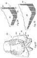
- cutter 10is formed on an infiltrated matrix bit body 12. It is to be appreciated that the present invention can be equally well implemented in a drill bit having a body which is cast or otherwise formed and can be implemented on a cutter mounted on a stud or on a drill bit of the type in which the cutters are brazed to a bit body.
- Cutter 10includes a cutting slug 14 in which a plurality of polycrystalline diamond (PCD) cutting elements, two of which are elements 16, 18, are disposed. The cutting elements are leached using a known process to increase the resistance of the cutting elements to heat.
- Cutting slug 14can be formed by a variety of methods,such as conventional hot-press techniques or by infiltration techniques separately from the matrix body or may be formed simultaneously through infiltration techniques with the bit body. Both techniques for forming the cutting slug are known in the art.
- Fig. 12indicated generally at 20 is a portion of a cutter including a PCD cutting element 22.
- Fig. 12illustrates the position of a plurality of PCD elements held within a cutting slug, which is not shown to reveal the geometry and relative positions of the PCD cutting elements.
- PCD cutting element 22is substantially identical in shape and size to PCD cutting elements 16, 18.
- Element 22further includes an end surface 24 which is coplanar with the end surfaces of a number of the other cutting elements. End surface 24 and the other PCD element end surfaces coplanar therewith define a portion of a cutting face.
- Cutting element 22includes an edge 26 which extends into the cutting slug from the cutting face and which defines the thickness of cutting element 22.
- the cutting elementsare arranged in two parallel layers 23, 25.
- each of cutting elements 16, 18also include a planar end surface 28, 30, respectively.
- each of the PCD cutting elementshas a preselected thickness which determines the depth to which each cutting element extends into cutting slug 14 from surface 32.
- the cutting elements of cutter 10are arranged in rows, four of which are rows 34, 36, 38, 40.
- the cutting elements in rows 34, 38are made of PCD material having a first hardness while the cutting elements in rows 36, 40 are made of a PCD material having a second lower hardness.
- the PCD elements in alternate rows, like rows 34, 38are made up of PCD elements having a first hardness.
- PCD elements in the interleaved rows, like rows 36,40are made up of PCD elements having a second lower hardness.
- the elements having the first hardnessare marked with vertical parallel lines (only to provide a visual indication of which elements have the first hardness) while the elements having the second lower hardness are unmarked.
- the cutting edgewears.
- the cutting edgecomprises which comprises the generally upper portion of cutting slug 14.
- Such wearis illustrated in Fig. 2.
- the matrix material from which cutting slug 14 is formedwears very rapidly while the cutting elements having a second lower hardness, like cutting element 18, wear less rapidly.
- the cutting elements with the first hardness, like cutting element 16,wear least rapidly of all.
- a nonuniform cutting edge, like that shown in Fig. 2is thus presented. Under certain conditions, which are known in the art, such a nonuniform cutting edge enhances cutting action of the cutter as contrasted with a cutter having a curvilinear edge.
- Cutter 42includes cutting slug 44 bonded to a steel or tungsten carbide stud 46.
- Cutting slug 44like cutting slug 14 in Figs. 1 and 2, comprises an array of a plurality of synthetic PCD elements, like elements 48, 50.
- cutting slug 44may be separately formed by conventional hot-press techniques or by infiltration techniques separately from the bit body matrix or may be formed simultaneously therewith through infiltration techniques with the bit body.
- the cutting elements having vertical lines thereonare made from PCD material which more hard than the PCD material from which the unmarked cutting elements are made. It should be noted that techniques for producing PCD cutting elements of different shapes and hardness are well known in the art. The cutting elements of Fig. 3 will wear in a manner which produces an irregular cutting edge.
- a portion of a cutting face 52 formed on a cutterincludes PCD elements having two wear ratios, one of which is cutting element 54 and another of which is cutting element 56, arranged in alternate rows as shown.
- wearcreates an irregular cutting edge on the cutter upon which cutting face 52 is formed.
- Figs. 5 and 6illustrate views similar to Fig. 4 but with cutting elements having triangular shapes, in Fig. 5, and hexagonal shapes in Figs. 6.
- the embodiments of Figs. 5 and 6incorporate cutting elements having different wear ratios in alternate horizontal rows rather than in alternate vertical rows as in the embodiment of Figs. 1 and 2.
- the cutting edgecomprises a generally nonuniform shape, due to the triangular configuration of cutting elements in Fig. 5 and the hexagonal shape in Fig. 6, having substantially uniform wear ratios.
- the cutting edgealternates between having cutting elements made up of one wear ratio and cutting elements made up of another.
- a cuttercan be selected which presents a cutting edge having the appropriate wear ratio for each layer of the formation through which it cuts.
- Fig. 8illustrates a cutting face 57 made up of PCD cutting elements having a substantially uniform wear ratio.
- Cutting face 57is formed on a cutter 58, in Figs. 9A and 9B, which is mounted on a drill bit 60.
- a plurality of cuttersare arranged in four blades 62, 64, 66, 68.
- the cutters on blades 64, 68are made from PCD material which has a wear ratio resulting in faster wear than the wear ratio of the cutters on blade 62, 66 are made.
- the cutters on blades 62, 66are made from PCD material having a single wear ratio.
- the weight of the bitis primarily on the hard cutters, i.e., those in blades 62, 66, while the relatively faster-wearing cutters in blades 64, 68 serve to stabilize bit rotation.
- the rapid penetration of a two-bladed bitis obtained with a four-bladed bit, which provides increased stability over that normally exhibited in a two-bladed bit.
- Bit 70includes a bit body 80 and an exterior surface or crown 82 upon which the cutters are mounted.
- Cutters 72, 76are each made up of PCD material having a low wear ratio, which tends to resist wear more so than material with a high wear ratio, while cutters 74, 78 are made up of material having a higher wear ratio.
- the cuttersmay be arranged in blades or may be in any configuration in which the cutters alternate between high and low wear ratio PCD cutting elements.
- Fig. 11illustrates the wear which occurs after a period of drilling with bit 70.
- cutters 74, 78wear at a faster rate than cutters 72, 76. Such action creates adjacent cuts having different depths. Because of the differing depths of cut, at least some of the formation being cut is not laterally constrained and therefore can be cut more easily.
- Figs. 7 and 12 to 16show two-layer structures of PCD elements. However, the concrete embodiments in Figs 7 and 12 to 16 do not form part of the invention.
- Fig. 12includes two layers 23, 25 of PCD elements.
- all of the PCD elementsare of the same wear ratio.
- Each of the cutting elements, like element 22,includes a pair of opposed end faces, like end face 24, which is exposed on the cutting face of the cutter. Another end face (not visible) is also triangular in shape and is substantially parallel to end face 24.
- Each of the other PCD elementsis similarly constructed. The arrangement of the elements is as shown in Fig. 12.
- the area of the diamond exposed to the side of the cutter having the cutting edge thereonis increased because of the addition of an extra layer, layer 25, of PCD elements. Because the wear rate of the cutting edge is proportional to the total surface area of PCD element exposed adjacent the cutting edge, wear is reduced.
- each of the PCD elements in layer 23is aligned with a corresponding element in layer 25.
- Figs. 13-15illustrate different embodiments of a two-layer cutter in which the cutting elements are substantially identical in shape to one another but are offset laterally from one layer to the next. In the view of Fig. 16, the first and second layers are spaced laterally from one another in addition to being offset.
- each layerincludes PCD elements all having substantially the same wear ratio. It should be noted however that it is contemplated to be within the scope of the invention to provide a first layer of PCD elements, each of which includes an end face coplanar with the cutting face of the cutter, having a first wear ratio and a second layer of PCD elements, behind the first layer as illustrated in the drawings, having a second different wear ratio.
- a cuttercan be "tailored" for optimum cutting through a particular formation having adjacent layers of rock which have different wear ratio.
- a person having ordinary skill in the art, and knowledge of a particular formation,can select PCD elements in each layer having appropriate thicknesses and wear ratios so that as a first layer is being worn through at the cutting edge, the drill bit enters the next-downward rock layer in the formation.
- the next layer of PCD elements, which is optimized for the rock layer the bit is entering,is thus exposed to provide cutting action.
- the same effect as described above when using PCD elements of one wear ratio in layer 23 and PCD elements of another wear ratio in layer 25may be achieved in another manner.
- all of the elementshave the substantially the same wear ratio; the thickness, however, of the elements in one layer is different from that of the other layer.
- each of the other PCD elements in layer 23are identical to PCD element 22, i.e., they are of a uniform thickness equal to one-half of the thickness of elements in row 25. Since the rate of wear is dependent upon the geometry of the PCD element being worn, the elements in layer 23 wear twice as fast as those in layer 25 thus exposing the layer 25 elements on the cutting edge after the elements in layer 23 are sufficiently worn. Thus, the same effect is achieved by using PCD elements having the same wear ratio but varying thicknesses when using PCD elements of uniform thickness and different wear ratios.
- a row of PCD elements 90, 92, 94, 96, 98Each of the elements include an end face, like end faces 100, 102 in elements 90, 92, respectively. It is to be appreciated that row 88 is maintained in position in a cutter matrix which includes additional PCD elements (not shown) above and below row 88. All of the PCD elements have end faces, like end faces 100, 102, which are coplanar with each other and with a planar surface of the matrix which, together with the end faces, form the cutting face of the cutter.
- alternate PCD elementsare substantially identical to one another with adjacent elements having different thickness.
- element 90is one-half as thick as element 92.
- the relatively thin cutting elementsthree of which are 90, 94, 98 wear at a different rate from that of the relatively thick elements.
- the orientation of the PCD elementsinitially exposes more surface area of the relatively thin elements to wear than that of the relatively thick elements.
- FIG. 17AThe same type of wear pattern as the cutter in Fig. 17A is created in the cutter of Fig. 17B in which a row of PCD elements is indicated generally at 104.
- Row 104includes elements 106, 108, 110, 112, 114.
- vertical lines on the end faces in the cutting surfaceindicate PCD elements with lower wear ratios than the PCD elements having unlined end faces.
- the hard PCD elements 108, 112are twice as hard as PCD elements 106, 110, 114, the same wear pattern when row 104 is in the cutting edge is created as when row 88 is in the cutting edge.
- Cutter 115includes a plurality of cutting elements, like cutting elements 117, 119 each of which present an exposed end surface which defines a portion of a spherical surface 121 which forms the cutting face of cutter 115.
- variations in the geometry and wear ratio of the cutting elements which make up the cutter surfacecreate an irregular cutting edge due to uneven rates of wear of the cutting elements.
- Bit 130includes alternating short and long blades, like blades 132, 134, respectively.
- Each of the bladesincludes a planar surface 136, 138, in Figs. 24 and 25, respectively, upon which a plurality of cutting elements, like those previously described herein, are mounted.
- the cutting elementsare mounted on the planar surfaces in groups, like groups 140, 142, 144 are mounted on surface 136.
- Each of the groupsare referred to herein as cutters although all of the cutting elements on each blade may also be considered to form a single large cutter.
- each of the cutting elementsis triangular in shape. The variations in wear ratio and cutting element geometry previously described herein in connection with cutting elements mounted on cutters may be equally well implemented in the cutting elements mounted on bit 130.
- the bit 130 cutting elementsare mounted on surfaces 136, 138 via brazing.
- matrix materialencompasses the materials used to braze the individual cutting elements to a drill bit surface, like the cutting elements on bit 130 are brazed to the planar surfaces like surfaces 136, 138.
- Known brazing methodsmay therefore be used both to mount cutters on a drill bit, as previously described herein, and to mount cutting elements on a bit, like the triangular cutting elements are mounted on surfaces 136, 138.
- the cutting elementsneed not be triangular in shape but can assume other configurations as described herein.
- Bit 116includes a bit body 118 and a shank 120 which is used to mount the bit on a conventional pneumatic or hydraulic hammer (not shown). Such a device typically vibrates with a small range of motion against the bottom of a hole being drilled.
- the bitincludes an impact surface 122 which is made up of a plurality of PCD elements, which are bonded to or integrally formed with bit body 118 in a known manner.
- an abrasive diamond surfacecan be created on the bit body by chemical vapor deposition.
- the PCD elements which form surface 122are repeatedly impacted against the bottom of a hole being dug by the hammer upon which the bit is mounted. Each impact places the PCD elements in compression which they are particularly well suited to withstand. Additionally, the PCD surface exposed on surface 122 provides a good abrasion surface.
- Fig. 20illustrates how the PCD elements are layered.
- the PCD elementsmay have different wear ratios and the element layers can be of varying thicknesses.
- bit 128is another embodiment of a percussive drill bit constructed in accordance with the present invention which has a differently shaped bit body and which therefore presents an impact surface different from bit 116.
- bit 116multiple layers of PCD elements are used to create the impact surface in bit 128 as illustrated in Fig. 20.
- the boundaries of the end facecan take any geometric or irregular form.
- the cuter cutting facecan be planar, hemispherical, wavy or any other shape.
- the distribution of cutting elements with different wear ratios or thicknessescan be in a regular repeating pattern or may be random. A random arrangement for use in a formation in which the hardness varies may provide improved rates of penetration over a cutter in which there is a regular pattern.
Landscapes
- Engineering & Computer Science (AREA)
- Life Sciences & Earth Sciences (AREA)
- Mining & Mineral Resources (AREA)
- Geology (AREA)
- Mechanical Engineering (AREA)
- Physics & Mathematics (AREA)
- Environmental & Geological Engineering (AREA)
- Fluid Mechanics (AREA)
- General Life Sciences & Earth Sciences (AREA)
- Geochemistry & Mineralogy (AREA)
- Chemical & Material Sciences (AREA)
- Crystallography & Structural Chemistry (AREA)
- Earth Drilling (AREA)
Description
Claims (22)
- Cutter (10;42;58;115) for a rotating drag bit (60;70;130; 116) comprising:a cutting face;a first group of cutting elements (16;48;56;62,66;72,76;90,94,98;106,110,114)each having at least one end surface and being subject to wear at a first rate,said end surfaces being exposed on said cutting face;a second group of cutting elements (18;50,54;64,68;74,78;92,96,98;108,112)each having at least one end surface and being subject to wear at a secondrate different from said first rate, said second group end surfaces also beingexposed on said cutting face; anda cutting slug (14;44) formed of matrix material and having said first andsecond group of cutting elements disposed therein, said cutting face (52) beingdefined by a plurality of end surfaces (28;30) exposed on said cutting face (52),
characterized in thatsaid elements (16;48;56;62,66;72,76;90,94,98;106,110,114) in said first groupare arranged in a first row (34,38), said elements(18;50,54;64,68;74,78;92,96,98; 108,112) in said second group are arranged ina second row (36,40), and
that said rows (34,38;36,40) are adjacent to one another. - Cutter according to claim 1,characterized in that said rows (34,38;36,40) aresubstantially parallel to one another.
- Cutter according to claim 1 or 2characterized in that said cutting element ofsaid first and second groups are made from polycrystalline diamond (PCD).
- Cutter according to claim 3,characterized in that the cutting elements(90,94,98,92,96) of said first and second groups have substantially the samewear ratio and wherein the first group and said second group have different thicknesses thereby wearing the cutting elements in said second group at adifferent rate than those in said first group responsive to bit rotation.
- Cutter according to claim 3,characterized in that said first and secondgroups of cutting elements have substantially the same thicknesses andwherein said first and second groups have different wear ratios thereby wearingthe elements in the second group (18;50, 56;64,68; 74,78;108,112) at adifferent rate than those in said first group (16;48;56;62,66;72,76;106,110,114)responsive to bit rotation.
- Cutter according to one of claims 1 to 5,characterized in that said cuttingelements are arranged in two layers (23,25) one above the other, wherein thefirst layer provides a cutting edge and when the first layer is being worn throughat said cutting edge the next layer is exposed to provide cutting action.
- Cutter according to one of claims 1 to 6,characterized in that said cuttingface (52) is substantially planar.
- Cutter according to one of claims 1 to 7,characterized in that exposed endsurfaces of the cutting elements (54,56) each have a substantially squareboundary.
- Cutter according to one of claims 1 to 7,characterized in that said exposedend surfaces (24;100,102) of the cutting elements(16,18;90,92,94,96,98;106,108,110,112,114) each have a substantially triangular boundary.
- Cutter according to one of claims 1 to 7,characterized in that said exposedend surfaces each have a substantially irregular boundary.
- Cutter according to one of claims 1 to 10,characterized in that the cuttingelements (16;48;56;62,66;72,76;90,94,98;106,110,114) are thermally stable,prefabricated polycrystalline diamond synthetic elements each having at leastone end surface;the matrix material of the cutting slug (14,44) fills the spaces between theplurality of cutting elements;a cutting edge formed on one side of said cutting face include side surfaces(27) presented by said polycrystalline diamond cutting elements, said cuttingedge including cutting elements which wear at different rates thereby forming acutting edge having a profile dependent upon the wear rate of the elementscomprising said cutting edge.
- Cutter according to claim 11,characterized in that said rows (,34,38,36,40)are oriented substantially normal to said cutting edge.
- Rotating drag bit comprising a plurality of cutters (58) of the type made fromcutting elements as defined in one of claims 1 to 12characterized in that saidcutters (58) are arranged in blades (62,64,55,68).
- Rotating drag bit according to claim 13,characterized in that the cutters inone of said blades are of the type which wear at said first rate and the cutters inanother of said blades are of the type which wear at said second rate.
- Rotating bit according to claim 14,characterized in that said drag bitcomprises four blades arranged at 90° intervals and wherein the cutters (58) inadjacent blades have cutters which wear at different rates.
- Rotating drag bit according to one of claims 13 to 15characterized in that thecutting elements on said cutters (58) have substantially the same wear ratioand that the cutting elements on said first cutter have a different thickness fromthe cutting elements on said second cutter thereby wearing the elements insaid second cutter at a different rate than those in said first cutter responsive tobit rotation.
- Rotating drag bit according to one of claims 13 to 15,characterized in thatthe cutting elements on said first and second cutters (58) have substantially thesame thickness and wherein the cutting elements on said first cutter have adifferent wear ratio from the cutting elements in said second cutter at a differentrate than those in said first cutter responsive to bit rotation.
- Rotating drill bit according to claim 13,characterized by a bit body (118)having a working surface profile of a type suitable for percussive drillingwherein said working surface repeatedly strikes an earth formation; andthat said cutting elements (124,126) are provided by a layer of polycrystallinediamond bonded to said bit body and having a surface which defines saidworking surface.
- Rotating drill bit according to claim 18,characterized in that said drill bitfurther comprises a second layer of polycrystalline diamond cutting elementsbonded to said first layer and wherein said working surface is defined on saidsecond layer.
- Rotating drill bit according to claim 19,characterized in that the cuttingelements in said second layer are offset relative to the cutting elements in saidfirst layer.
- A method of percussive drilling comprising the steps of:bonding a first layer of cutting elements to a working surface of a percussivedrill bit (116);bonding a second layer of such elements to said first layer;
wherein at least one layer comprises two groups of cutting elements (124,126)having a different wear rate;operating the percussive drill bit;repeatedly striking the drill bit against an earth formation in a manner whichcompresses the cutting elements each time the bit strikes the formation,comprising striking the second layer of such elements against the earthformation. - The method of claim 21,characterized in that the step of bonding a secondlayer of such elements to said first layer comprises the step of offsetting saidsecond layer relative to said first layer.
Applications Claiming Priority (2)
| Application Number | Priority Date | Filing Date | Title |
|---|---|---|---|
| US07/817,861US5238074A (en) | 1992-01-06 | 1992-01-06 | Mosaic diamond drag bit cutter having a nonuniform wear pattern |
| US817861 | 1992-01-06 |
Publications (3)
| Publication Number | Publication Date |
|---|---|
| EP0554568A2 EP0554568A2 (en) | 1993-08-11 |
| EP0554568A3 EP0554568A3 (en) | 1993-12-01 |
| EP0554568B1true EP0554568B1 (en) | 2000-02-16 |
Family
ID=25224037
Family Applications (1)
| Application Number | Title | Priority Date | Filing Date |
|---|---|---|---|
| EP92122088AExpired - LifetimeEP0554568B1 (en) | 1992-01-06 | 1992-12-29 | Mosaic diamond drag bit cutter having a nonuniform wear pattern |
Country Status (4)
| Country | Link |
|---|---|
| US (1) | US5238074A (en) |
| EP (1) | EP0554568B1 (en) |
| AU (1) | AU3044992A (en) |
| DE (1) | DE69230687D1 (en) |
Cited By (47)
| Publication number | Priority date | Publication date | Assignee | Title |
|---|---|---|---|---|
| US6857487B2 (en) | 2002-12-30 | 2005-02-22 | Weatherford/Lamb, Inc. | Drilling with concentric strings of casing |
| US6896075B2 (en) | 2002-10-11 | 2005-05-24 | Weatherford/Lamb, Inc. | Apparatus and methods for drilling with casing |
| US6899186B2 (en) | 2002-12-13 | 2005-05-31 | Weatherford/Lamb, Inc. | Apparatus and method of drilling with casing |
| US6953096B2 (en) | 2002-12-31 | 2005-10-11 | Weatherford/Lamb, Inc. | Expandable bit with secondary release device |
| US6994176B2 (en) | 2002-07-29 | 2006-02-07 | Weatherford/Lamb, Inc. | Adjustable rotating guides for spider or elevator |
| US7004264B2 (en) | 2002-03-16 | 2006-02-28 | Weatherford/Lamb, Inc. | Bore lining and drilling |
| US7013997B2 (en) | 1994-10-14 | 2006-03-21 | Weatherford/Lamb, Inc. | Methods and apparatus for cementing drill strings in place for one pass drilling and completion of oil and gas wells |
| US7036610B1 (en) | 1994-10-14 | 2006-05-02 | Weatherford / Lamb, Inc. | Apparatus and method for completing oil and gas wells |
| US7040420B2 (en) | 1994-10-14 | 2006-05-09 | Weatherford/Lamb, Inc. | Methods and apparatus for cementing drill strings in place for one pass drilling and completion of oil and gas wells |
| US7048050B2 (en) | 1994-10-14 | 2006-05-23 | Weatherford/Lamb, Inc. | Method and apparatus for cementing drill strings in place for one pass drilling and completion of oil and gas wells |
| US7073598B2 (en) | 2001-05-17 | 2006-07-11 | Weatherford/Lamb, Inc. | Apparatus and methods for tubular makeup interlock |
| US7090021B2 (en) | 1998-08-24 | 2006-08-15 | Bernd-Georg Pietras | Apparatus for connecting tublars using a top drive |
| US7093675B2 (en) | 2000-08-01 | 2006-08-22 | Weatherford/Lamb, Inc. | Drilling method |
| US7096982B2 (en) | 2003-02-27 | 2006-08-29 | Weatherford/Lamb, Inc. | Drill shoe |
| US7100710B2 (en) | 1994-10-14 | 2006-09-05 | Weatherford/Lamb, Inc. | Methods and apparatus for cementing drill strings in place for one pass drilling and completion of oil and gas wells |
| US7100713B2 (en) | 2000-04-28 | 2006-09-05 | Weatherford/Lamb, Inc. | Expandable apparatus for drift and reaming borehole |
| US7108084B2 (en) | 1994-10-14 | 2006-09-19 | Weatherford/Lamb, Inc. | Methods and apparatus for cementing drill strings in place for one pass drilling and completion of oil and gas wells |
| US7117957B2 (en) | 1998-12-22 | 2006-10-10 | Weatherford/Lamb, Inc. | Methods for drilling and lining a wellbore |
| US7128161B2 (en) | 1998-12-24 | 2006-10-31 | Weatherford/Lamb, Inc. | Apparatus and methods for facilitating the connection of tubulars using a top drive |
| US7128154B2 (en) | 2003-01-30 | 2006-10-31 | Weatherford/Lamb, Inc. | Single-direction cementing plug |
| US7140445B2 (en) | 1997-09-02 | 2006-11-28 | Weatherford/Lamb, Inc. | Method and apparatus for drilling with casing |
| US7147068B2 (en) | 1994-10-14 | 2006-12-12 | Weatherford / Lamb, Inc. | Methods and apparatus for cementing drill strings in place for one pass drilling and completion of oil and gas wells |
| US7188687B2 (en) | 1998-12-22 | 2007-03-13 | Weatherford/Lamb, Inc. | Downhole filter |
| US7191840B2 (en) | 2003-03-05 | 2007-03-20 | Weatherford/Lamb, Inc. | Casing running and drilling system |
| US7213656B2 (en) | 1998-12-24 | 2007-05-08 | Weatherford/Lamb, Inc. | Apparatus and method for facilitating the connection of tubulars using a top drive |
| US7216727B2 (en) | 1999-12-22 | 2007-05-15 | Weatherford/Lamb, Inc. | Drilling bit for drilling while running casing |
| US7219744B2 (en) | 1998-08-24 | 2007-05-22 | Weatherford/Lamb, Inc. | Method and apparatus for connecting tubulars using a top drive |
| US7228901B2 (en) | 1994-10-14 | 2007-06-12 | Weatherford/Lamb, Inc. | Method and apparatus for cementing drill strings in place for one pass drilling and completion of oil and gas wells |
| US7264067B2 (en) | 2003-10-03 | 2007-09-04 | Weatherford/Lamb, Inc. | Method of drilling and completing multiple wellbores inside a single caisson |
| US7284617B2 (en) | 2004-05-20 | 2007-10-23 | Weatherford/Lamb, Inc. | Casing running head |
| US7303022B2 (en) | 2002-10-11 | 2007-12-04 | Weatherford/Lamb, Inc. | Wired casing |
| US7311148B2 (en) | 1999-02-25 | 2007-12-25 | Weatherford/Lamb, Inc. | Methods and apparatus for wellbore construction and completion |
| US7325610B2 (en) | 2000-04-17 | 2008-02-05 | Weatherford/Lamb, Inc. | Methods and apparatus for handling and drilling with tubulars or casing |
| US7334650B2 (en) | 2000-04-13 | 2008-02-26 | Weatherford/Lamb, Inc. | Apparatus and methods for drilling a wellbore using casing |
| US7360594B2 (en) | 2003-03-05 | 2008-04-22 | Weatherford/Lamb, Inc. | Drilling with casing latch |
| US7370707B2 (en) | 2003-04-04 | 2008-05-13 | Weatherford/Lamb, Inc. | Method and apparatus for handling wellbore tubulars |
| US7413020B2 (en) | 2003-03-05 | 2008-08-19 | Weatherford/Lamb, Inc. | Full bore lined wellbores |
| US7503397B2 (en) | 2004-07-30 | 2009-03-17 | Weatherford/Lamb, Inc. | Apparatus and methods of setting and retrieving casing with drilling latch and bottom hole assembly |
| US7509722B2 (en) | 1997-09-02 | 2009-03-31 | Weatherford/Lamb, Inc. | Positioning and spinning device |
| US7617866B2 (en) | 1998-08-24 | 2009-11-17 | Weatherford/Lamb, Inc. | Methods and apparatus for connecting tubulars using a top drive |
| US7650944B1 (en) | 2003-07-11 | 2010-01-26 | Weatherford/Lamb, Inc. | Vessel for well intervention |
| US7712523B2 (en) | 2000-04-17 | 2010-05-11 | Weatherford/Lamb, Inc. | Top drive casing system |
| US7730965B2 (en) | 2002-12-13 | 2010-06-08 | Weatherford/Lamb, Inc. | Retractable joint and cementing shoe for use in completing a wellbore |
| US7857052B2 (en) | 2006-05-12 | 2010-12-28 | Weatherford/Lamb, Inc. | Stage cementing methods used in casing while drilling |
| US7938201B2 (en) | 2002-12-13 | 2011-05-10 | Weatherford/Lamb, Inc. | Deep water drilling with casing |
| USRE42877E1 (en) | 2003-02-07 | 2011-11-01 | Weatherford/Lamb, Inc. | Methods and apparatus for wellbore construction and completion |
| US8276689B2 (en) | 2006-05-22 | 2012-10-02 | Weatherford/Lamb, Inc. | Methods and apparatus for drilling with casing |
Families Citing this family (133)
| Publication number | Priority date | Publication date | Assignee | Title |
|---|---|---|---|---|
| GB9125558D0 (en)* | 1991-11-30 | 1992-01-29 | Camco Drilling Group Ltd | Improvements in or relating to cutting elements for rotary drill bits |
| US5607024A (en)* | 1995-03-07 | 1997-03-04 | Smith International, Inc. | Stability enhanced drill bit and cutting structure having zones of varying wear resistance |
| US6478831B2 (en) | 1995-06-07 | 2002-11-12 | Ultimate Abrasive Systems, L.L.C. | Abrasive surface and article and methods for making them |
| US6453899B1 (en)* | 1995-06-07 | 2002-09-24 | Ultimate Abrasive Systems, L.L.C. | Method for making a sintered article and products produced thereby |
| US6482244B2 (en) | 1995-06-07 | 2002-11-19 | Ultimate Abrasive Systems, L.L.C. | Process for making an abrasive sintered product |
| US5667028A (en)* | 1995-08-22 | 1997-09-16 | Smith International, Inc. | Multiple diamond layer polycrystalline diamond composite cutters |
| US5669744A (en)* | 1996-01-05 | 1997-09-23 | Hines; Donald G. | Rotary chisel |
| US5706906A (en)* | 1996-02-15 | 1998-01-13 | Baker Hughes Incorporated | Superabrasive cutting element with enhanced durability and increased wear life, and apparatus so equipped |
| US5924501A (en)* | 1996-02-15 | 1999-07-20 | Baker Hughes Incorporated | Predominantly diamond cutting structures for earth boring |
| US6390210B1 (en)* | 1996-04-10 | 2002-05-21 | Smith International, Inc. | Rolling cone bit with gage and off-gage cutter elements positioned to separate sidewall and bottom hole cutting duty |
| US5967245A (en)* | 1996-06-21 | 1999-10-19 | Smith International, Inc. | Rolling cone bit having gage and nestled gage cutter elements having enhancements in materials and geometry to optimize borehole corner cutting duty |
| US6009963A (en)* | 1997-01-14 | 2000-01-04 | Baker Hughes Incorporated | Superabrasive cutting element with enhanced stiffness, thermal conductivity and cutting efficiency |
| US5967249A (en)* | 1997-02-03 | 1999-10-19 | Baker Hughes Incorporated | Superabrasive cutters with structure aligned to loading and method of drilling |
| US5881830A (en)* | 1997-02-14 | 1999-03-16 | Baker Hughes Incorporated | Superabrasive drill bit cutting element with buttress-supported planar chamfer |
| US5979578A (en) | 1997-06-05 | 1999-11-09 | Smith International, Inc. | Multi-layer, multi-grade multiple cutting surface PDC cutter |
| US6202771B1 (en) | 1997-09-23 | 2001-03-20 | Baker Hughes Incorporated | Cutting element with controlled superabrasive contact area, drill bits so equipped |
| US6045440A (en)* | 1997-11-20 | 2000-04-04 | General Electric Company | Polycrystalline diamond compact PDC cutter with improved cutting capability |
| US6241036B1 (en) | 1998-09-16 | 2001-06-05 | Baker Hughes Incorporated | Reinforced abrasive-impregnated cutting elements, drill bits including same |
| EP1006257B1 (en)* | 1998-12-04 | 2004-02-25 | Camco International (UK) Ltd. | A drag-type Rotary Drill Bit |
| US6371226B1 (en) | 1998-12-04 | 2002-04-16 | Camco International Inc. | Drag-type rotary drill bit |
| US6193000B1 (en) | 1999-11-22 | 2001-02-27 | Camco International Inc. | Drag-type rotary drill bit |
| GB9827600D0 (en)* | 1998-12-15 | 1999-02-10 | De Beers Ind Diamond | Abrasive product |
| US6248447B1 (en)* | 1999-09-03 | 2001-06-19 | Camco International (Uk) Limited | Cutting elements and methods of manufacture thereof |
| GB2362903B (en)* | 2000-05-30 | 2002-12-24 | Baker Hughes Inc | Laminated and composite impregnated cutting structures for drill bits |
| US6592985B2 (en) | 2000-09-20 | 2003-07-15 | Camco International (Uk) Limited | Polycrystalline diamond partially depleted of catalyzing material |
| DE60140617D1 (en) | 2000-09-20 | 2010-01-07 | Camco Int Uk Ltd | POLYCRYSTALLINE DIAMOND WITH A SURFACE ENRICHED ON CATALYST MATERIAL |
| WO2002024603A1 (en) | 2000-09-20 | 2002-03-28 | Camco International (Uk) Limited | Polycrystalline diamond with a surface depleted of catalyzing material |
| WO2003083148A1 (en)* | 2002-03-28 | 2003-10-09 | Camco International (Uk) Limited | Polycrystalline material element with improved wear resistance and methods of manufacture thereof |
| KR101021461B1 (en)* | 2002-07-26 | 2011-03-16 | 미쓰비시 마테리알 가부시키가이샤 | Joining structure and joining method of cemented carbide member and diamond member, cutting pieces of excavating tool, cutting member, and excavating tool |
| US7048081B2 (en)* | 2003-05-28 | 2006-05-23 | Baker Hughes Incorporated | Superabrasive cutting element having an asperital cutting face and drill bit so equipped |
| US20050050801A1 (en)* | 2003-09-05 | 2005-03-10 | Cho Hyun Sam | Doubled-sided and multi-layered PCD and PCBN abrasive articles |
| US20050210755A1 (en)* | 2003-09-05 | 2005-09-29 | Cho Hyun S | Doubled-sided and multi-layered PCBN and PCD abrasive articles |
| GB2408735B (en)* | 2003-12-05 | 2009-01-28 | Smith International | Thermally-stable polycrystalline diamond materials and compacts |
| US7726420B2 (en)* | 2004-04-30 | 2010-06-01 | Smith International, Inc. | Cutter having shaped working surface with varying edge chamfer |
| US7647993B2 (en)* | 2004-05-06 | 2010-01-19 | Smith International, Inc. | Thermally stable diamond bonded materials and compacts |
| US7754333B2 (en)* | 2004-09-21 | 2010-07-13 | Smith International, Inc. | Thermally stable diamond polycrystalline diamond constructions |
| US7608333B2 (en)* | 2004-09-21 | 2009-10-27 | Smith International, Inc. | Thermally stable diamond polycrystalline diamond constructions |
| US8448725B2 (en)* | 2004-12-10 | 2013-05-28 | Smith International, Inc. | Impact resistant PDC drill bit |
| US7681669B2 (en) | 2005-01-17 | 2010-03-23 | Us Synthetic Corporation | Polycrystalline diamond insert, drill bit including same, and method of operation |
| US7350601B2 (en)* | 2005-01-25 | 2008-04-01 | Smith International, Inc. | Cutting elements formed from ultra hard materials having an enhanced construction |
| US7497280B2 (en) | 2005-01-27 | 2009-03-03 | Baker Hughes Incorporated | Abrasive-impregnated cutting structure having anisotropic wear resistance and drag bit including same |
| US8197936B2 (en) | 2005-01-27 | 2012-06-12 | Smith International, Inc. | Cutting structures |
| CA2535387C (en) | 2005-02-08 | 2013-05-07 | Smith International, Inc. | Thermally stable polycrystalline diamond cutting elements and bits incorporating the same |
| US7493973B2 (en)* | 2005-05-26 | 2009-02-24 | Smith International, Inc. | Polycrystalline diamond materials having improved abrasion resistance, thermal stability and impact resistance |
| US7377341B2 (en) | 2005-05-26 | 2008-05-27 | Smith International, Inc. | Thermally stable ultra-hard material compact construction |
| US8789627B1 (en) | 2005-07-17 | 2014-07-29 | Us Synthetic Corporation | Polycrystalline diamond cutter with improved abrasion and impact resistance and method of making the same |
| US8020643B2 (en)* | 2005-09-13 | 2011-09-20 | Smith International, Inc. | Ultra-hard constructions with enhanced second phase |
| US7726421B2 (en) | 2005-10-12 | 2010-06-01 | Smith International, Inc. | Diamond-bonded bodies and compacts with improved thermal stability and mechanical strength |
| CN101395335B (en)* | 2006-01-26 | 2013-04-17 | 犹他大学研究基金会 | Polycrystalline abrasive composite cutter |
| US7628234B2 (en) | 2006-02-09 | 2009-12-08 | Smith International, Inc. | Thermally stable ultra-hard polycrystalline materials and compacts |
| US8066087B2 (en) | 2006-05-09 | 2011-11-29 | Smith International, Inc. | Thermally stable ultra-hard material compact constructions |
| US8028771B2 (en) | 2007-02-06 | 2011-10-04 | Smith International, Inc. | Polycrystalline diamond constructions having improved thermal stability |
| US7942219B2 (en) | 2007-03-21 | 2011-05-17 | Smith International, Inc. | Polycrystalline diamond constructions having improved thermal stability |
| US7845435B2 (en)* | 2007-04-05 | 2010-12-07 | Baker Hughes Incorporated | Hybrid drill bit and method of drilling |
| US7841426B2 (en)* | 2007-04-05 | 2010-11-30 | Baker Hughes Incorporated | Hybrid drill bit with fixed cutters as the sole cutting elements in the axial center of the drill bit |
| US20100025119A1 (en) | 2007-04-05 | 2010-02-04 | Baker Hughes Incorporated | Hybrid drill bit and method of using tsp or mosaic cutters on a hybrid bit |
| US8499861B2 (en) | 2007-09-18 | 2013-08-06 | Smith International, Inc. | Ultra-hard composite constructions comprising high-density diamond surface |
| US7980334B2 (en) | 2007-10-04 | 2011-07-19 | Smith International, Inc. | Diamond-bonded constructions with improved thermal and mechanical properties |
| KR100942983B1 (en)* | 2007-10-16 | 2010-02-17 | 주식회사 하이닉스반도체 | Semiconductor device and manufacturing method |
| US20090120008A1 (en)* | 2007-11-09 | 2009-05-14 | Smith International, Inc. | Impregnated drill bits and methods for making the same |
| US8678111B2 (en) | 2007-11-16 | 2014-03-25 | Baker Hughes Incorporated | Hybrid drill bit and design method |
| US9297211B2 (en) | 2007-12-17 | 2016-03-29 | Smith International, Inc. | Polycrystalline diamond construction with controlled gradient metal content |
| US8534391B2 (en)* | 2008-04-21 | 2013-09-17 | Baker Hughes Incorporated | Cutting elements and earth-boring tools having grading features |
| US20120205160A1 (en) | 2011-02-11 | 2012-08-16 | Baker Hughes Incorporated | System and method for leg retention on hybrid bits |
| US20090272582A1 (en) | 2008-05-02 | 2009-11-05 | Baker Hughes Incorporated | Modular hybrid drill bit |
| US7819208B2 (en)* | 2008-07-25 | 2010-10-26 | Baker Hughes Incorporated | Dynamically stable hybrid drill bit |
| US8083012B2 (en) | 2008-10-03 | 2011-12-27 | Smith International, Inc. | Diamond bonded construction with thermally stable region |
| US20100089658A1 (en)* | 2008-10-13 | 2010-04-15 | Baker Hughes Incorporated | Drill bit with continuously sharp edge cutting elements |
| US8720609B2 (en) | 2008-10-13 | 2014-05-13 | Baker Hughes Incorporated | Drill bit with continuously sharp edge cutting elements |
| US8020641B2 (en)* | 2008-10-13 | 2011-09-20 | Baker Hughes Incorporated | Drill bit with continuously sharp edge cutting elements |
| US20100089661A1 (en)* | 2008-10-13 | 2010-04-15 | Baker Hughes Incorporated | Drill bit with continuously sharp edge cutting elements |
| US9439277B2 (en)* | 2008-10-23 | 2016-09-06 | Baker Hughes Incorporated | Robotically applied hardfacing with pre-heat |
| US8948917B2 (en)* | 2008-10-29 | 2015-02-03 | Baker Hughes Incorporated | Systems and methods for robotic welding of drill bits |
| US8450637B2 (en) | 2008-10-23 | 2013-05-28 | Baker Hughes Incorporated | Apparatus for automated application of hardfacing material to drill bits |
| US8047307B2 (en)* | 2008-12-19 | 2011-11-01 | Baker Hughes Incorporated | Hybrid drill bit with secondary backup cutters positioned with high side rake angles |
| MX2011006187A (en)* | 2008-12-31 | 2011-06-20 | Baker Hughes Inc | Method and apparatus for automated application of hardfacing material to rolling cutters of hybrid-type earth boring drill bits, hybrid drill bits comprising such hardfaced steel-toothed cutting elements, and methods of use thereof. |
| US20100181116A1 (en)* | 2009-01-16 | 2010-07-22 | Baker Hughes Incororated | Impregnated drill bit with diamond pins |
| US8141664B2 (en)* | 2009-03-03 | 2012-03-27 | Baker Hughes Incorporated | Hybrid drill bit with high bearing pin angles |
| US20100242375A1 (en)* | 2009-03-30 | 2010-09-30 | Hall David R | Double Sintered Thermally Stable Polycrystalline Diamond Cutting Elements |
| US7972395B1 (en) | 2009-04-06 | 2011-07-05 | Us Synthetic Corporation | Superabrasive articles and methods for removing interstitial materials from superabrasive materials |
| US8951317B1 (en) | 2009-04-27 | 2015-02-10 | Us Synthetic Corporation | Superabrasive elements including ceramic coatings and methods of leaching catalysts from superabrasive elements |
| US8056651B2 (en)* | 2009-04-28 | 2011-11-15 | Baker Hughes Incorporated | Adaptive control concept for hybrid PDC/roller cone bits |
| US8590130B2 (en) | 2009-05-06 | 2013-11-26 | Smith International, Inc. | Cutting elements with re-processed thermally stable polycrystalline diamond cutting layers, bits incorporating the same, and methods of making the same |
| CA2760944A1 (en) | 2009-05-06 | 2010-11-11 | Smith International, Inc. | Methods of making and attaching tsp material for forming cutting elements, cutting elements having such tsp material and bits incorporating such cutting elements |
| US8459378B2 (en) | 2009-05-13 | 2013-06-11 | Baker Hughes Incorporated | Hybrid drill bit |
| US8567531B2 (en) | 2009-05-20 | 2013-10-29 | Smith International, Inc. | Cutting elements, methods for manufacturing such cutting elements, and tools incorporating such cutting elements |
| US8783389B2 (en) | 2009-06-18 | 2014-07-22 | Smith International, Inc. | Polycrystalline diamond cutting elements with engineered porosity and method for manufacturing such cutting elements |
| US8157026B2 (en) | 2009-06-18 | 2012-04-17 | Baker Hughes Incorporated | Hybrid bit with variable exposure |
| US8887839B2 (en) | 2009-06-25 | 2014-11-18 | Baker Hughes Incorporated | Drill bit for use in drilling subterranean formations |
| RU2012103935A (en) | 2009-07-08 | 2013-08-20 | Бейкер Хьюз Инкорпорейтед | CUTTING ELEMENT AND METHOD FOR ITS FORMATION |
| BR112012000535A2 (en)* | 2009-07-08 | 2019-09-24 | Baker Hughes Incorporatled | cutting element for a drill bit used for drilling underground formations |
| EP2479003A3 (en) | 2009-07-27 | 2013-10-02 | Baker Hughes Incorporated | Abrasive article |
| US9352447B2 (en) | 2009-09-08 | 2016-05-31 | Us Synthetic Corporation | Superabrasive elements and methods for processing and manufacturing the same using protective layers |
| CA2773897A1 (en) | 2009-09-16 | 2011-03-24 | Baker Hughes Incorporated | External, divorced pdc bearing assemblies for hybrid drill bits |
| US8347989B2 (en)* | 2009-10-06 | 2013-01-08 | Baker Hughes Incorporated | Hole opener with hybrid reaming section and method of making |
| US8448724B2 (en)* | 2009-10-06 | 2013-05-28 | Baker Hughes Incorporated | Hole opener with hybrid reaming section |
| US8590643B2 (en)* | 2009-12-07 | 2013-11-26 | Element Six Limited | Polycrystalline diamond structure |
| US8936109B2 (en) | 2010-06-24 | 2015-01-20 | Baker Hughes Incorporated | Cutting elements for cutting tools |
| CN103080458B (en) | 2010-06-29 | 2016-01-20 | 贝克休斯公司 | Drill bit with anti-drill bit recycling groove structure |
| US8978786B2 (en) | 2010-11-04 | 2015-03-17 | Baker Hughes Incorporated | System and method for adjusting roller cone profile on hybrid bit |
| US9540882B2 (en) | 2010-11-10 | 2017-01-10 | Halliburton Energy Services, Inc. | System and method of configuring drilling tools utilizing a critical depth of cut control curve |
| US20120199395A1 (en)* | 2011-02-07 | 2012-08-09 | Lynde Gerald D | Cutting elements having a pre-formed fracture plane for use in cutting tools |
| US9782857B2 (en) | 2011-02-11 | 2017-10-10 | Baker Hughes Incorporated | Hybrid drill bit having increased service life |
| US8858665B2 (en) | 2011-04-28 | 2014-10-14 | Robert Frushour | Method for making fine diamond PDC |
| US8741010B2 (en) | 2011-04-28 | 2014-06-03 | Robert Frushour | Method for making low stress PDC |
| WO2012152848A2 (en) | 2011-05-10 | 2012-11-15 | Element Six Abrasives S.A. | Tip for degradation tool and tool comprising same |
| US8974559B2 (en) | 2011-05-12 | 2015-03-10 | Robert Frushour | PDC made with low melting point catalyst |
| US8828110B2 (en) | 2011-05-20 | 2014-09-09 | Robert Frushour | ADNR composite |
| US9061264B2 (en) | 2011-05-19 | 2015-06-23 | Robert H. Frushour | High abrasion low stress PDC |
| US8778259B2 (en) | 2011-05-25 | 2014-07-15 | Gerhard B. Beckmann | Self-renewing cutting surface, tool and method for making same using powder metallurgy and densification techniques |
| US8261858B1 (en) | 2011-09-02 | 2012-09-11 | Halliburton Energy Services, Inc. | Element containing thermally stable polycrystalline diamond material and methods and assemblies for formation thereof |
| US8807247B2 (en) | 2011-06-21 | 2014-08-19 | Baker Hughes Incorporated | Cutting elements for earth-boring tools, earth-boring tools including such cutting elements, and methods of forming such cutting elements for earth-boring tools |
| US9144886B1 (en) | 2011-08-15 | 2015-09-29 | Us Synthetic Corporation | Protective leaching cups, leaching trays, and methods for processing superabrasive elements using protective leaching cups and leaching trays |
| WO2013074788A1 (en) | 2011-11-15 | 2013-05-23 | Baker Hughes Incorporated | Hybrid drill bits having increased drilling efficiency |
| US20130167451A1 (en)* | 2011-12-29 | 2013-07-04 | Diamond Innovations, Inc. | Cutter assembly with at least one island and a method of manufacturing a cutter assembly |
| EP2669033B1 (en) | 2012-05-29 | 2015-11-04 | Black & Decker Inc. | Cutting head for a drill bit. |
| RU2014122863A (en) | 2012-06-13 | 2015-12-10 | Варел Интернэшнл Инд., Л.П. | POLYCRYSTALLINE DIAMOND CUTTERS FOR HIGHER STRENGTH AND HEAT RESISTANCE |
| CN103510859B (en)* | 2012-06-21 | 2016-01-13 | 四川深远石油钻井工具股份有限公司 | Creep into the module cutter drill bits that specific pressure is controlled |
| US9428967B2 (en) | 2013-03-01 | 2016-08-30 | Baker Hughes Incorporated | Polycrystalline compact tables for cutting elements and methods of fabrication |
| US9550276B1 (en) | 2013-06-18 | 2017-01-24 | Us Synthetic Corporation | Leaching assemblies, systems, and methods for processing superabrasive elements |
| US9789587B1 (en) | 2013-12-16 | 2017-10-17 | Us Synthetic Corporation | Leaching assemblies, systems, and methods for processing superabrasive elements |
| US10807913B1 (en) | 2014-02-11 | 2020-10-20 | Us Synthetic Corporation | Leached superabrasive elements and leaching systems methods and assemblies for processing superabrasive elements |
| RU2689465C2 (en) | 2014-05-23 | 2019-05-28 | Бейкер Хьюз Инкорпорейтед | Combined drill bit with mechanical fastening of rock drilling unit elements |
| US9908215B1 (en) | 2014-08-12 | 2018-03-06 | Us Synthetic Corporation | Systems, methods and assemblies for processing superabrasive materials |
| US10011000B1 (en) | 2014-10-10 | 2018-07-03 | Us Synthetic Corporation | Leached superabrasive elements and systems, methods and assemblies for processing superabrasive materials |
| US11766761B1 (en) | 2014-10-10 | 2023-09-26 | Us Synthetic Corporation | Group II metal salts in electrolytic leaching of superabrasive materials |
| US11428050B2 (en) | 2014-10-20 | 2022-08-30 | Baker Hughes Holdings Llc | Reverse circulation hybrid bit |
| CN104772454A (en)* | 2015-03-24 | 2015-07-15 | 河南黄河旋风股份有限公司 | Diamond product pre-alloyed powder and manufacturing method thereof |
| US10723626B1 (en) | 2015-05-31 | 2020-07-28 | Us Synthetic Corporation | Leached superabrasive elements and systems, methods and assemblies for processing superabrasive materials |
| CN107709693A (en) | 2015-07-17 | 2018-02-16 | 哈里伯顿能源服务公司 | Center has the Mixed drilling bit for reversely rotating cutter |
| US10900291B2 (en) | 2017-09-18 | 2021-01-26 | Us Synthetic Corporation | Polycrystalline diamond elements and systems and methods for fabricating the same |
| CN109356600B (en)* | 2018-11-18 | 2024-04-23 | 中电建铁路建设投资集团有限公司 | Multi-layer diamond composite sheet cutting knife for shield |
| CN116988739B (en)* | 2023-09-26 | 2023-12-26 | 西南石油大学 | A high-density longitudinally arranged PDC drill bit |
Family Cites Families (34)
| Publication number | Priority date | Publication date | Assignee | Title |
|---|---|---|---|---|
| US2121202A (en)* | 1935-03-19 | 1938-06-21 | Robert J Killgore | Rotary bit |
| US2588782A (en)* | 1947-03-03 | 1952-03-11 | Waterland Tilmer Manville | Detachable drilling bit |
| US3298451A (en)* | 1963-12-19 | 1967-01-17 | Exxon Production Research Co | Drag bit |
| US3294186A (en)* | 1964-06-22 | 1966-12-27 | Tartan Ind Inc | Rock bits and methods of making the same |
| US3440773A (en)* | 1966-08-26 | 1969-04-29 | Norton Co | Abrasive cutting device |
| US3871486A (en)* | 1973-08-29 | 1975-03-18 | Bakerdrill Inc | Continuous coring system and apparatus |
| US3882749A (en)* | 1973-10-10 | 1975-05-13 | James C Tourek | Beavertooth cutting edge |
| US4128136A (en)* | 1977-12-09 | 1978-12-05 | Lamage Limited | Drill bit |
| US4351401A (en)* | 1978-06-08 | 1982-09-28 | Christensen, Inc. | Earth-boring drill bits |
| US4255165A (en)* | 1978-12-22 | 1981-03-10 | General Electric Company | Composite compact of interleaved polycrystalline particles and cemented carbide masses |
| US4252102A (en)* | 1979-04-19 | 1981-02-24 | Christensen, Inc. | Cutting element for processing rocks, metal or the like |
| US4441566A (en)* | 1980-06-23 | 1984-04-10 | Hughes Tool Company | Drill bit with dispersed cutter inserts |
| DE3114749C2 (en)* | 1981-04-11 | 1983-10-27 | Christensen, Inc., 84115 Salt Lake City, Utah | Wedge-shaped cutting link for rotary drill bits for deep drilling |
| US4452325A (en)* | 1982-09-27 | 1984-06-05 | Conoco Inc. | Composite structure for cutting tools |
| US4444281A (en)* | 1983-03-30 | 1984-04-24 | Reed Rock Bit Company | Combination drag and roller cutter drill bit |
| US4629373A (en)* | 1983-06-22 | 1986-12-16 | Megadiamond Industries, Inc. | Polycrystalline diamond body with enhanced surface irregularities |
| US4726718A (en)* | 1984-03-26 | 1988-02-23 | Eastman Christensen Co. | Multi-component cutting element using triangular, rectangular and higher order polyhedral-shaped polycrystalline diamond disks |
| US5028177A (en)* | 1984-03-26 | 1991-07-02 | Eastman Christensen Company | Multi-component cutting element using triangular, rectangular and higher order polyhedral-shaped polycrystalline diamond disks |
| US4525178A (en)* | 1984-04-16 | 1985-06-25 | Megadiamond Industries, Inc. | Composite polycrystalline diamond |
| US4592433A (en)* | 1984-10-04 | 1986-06-03 | Strata Bit Corporation | Cutting blank with diamond strips in grooves |
| US4694918A (en)* | 1985-04-29 | 1987-09-22 | Smith International, Inc. | Rock bit with diamond tip inserts |
| US4690228A (en)* | 1986-03-14 | 1987-09-01 | Eastman Christensen Company | Changeover bit for extended life, varied formations and steady wear |
| GB8612012D0 (en)* | 1986-05-16 | 1986-06-25 | Nl Petroleum Prod | Rotary drill bits |
| US4744427A (en)* | 1986-10-16 | 1988-05-17 | Eastman Christensen Company | Bit design for a rotating bit incorporating synthetic polycrystalline cutters |
| US4943488A (en)* | 1986-10-20 | 1990-07-24 | Norton Company | Low pressure bonding of PCD bodies and method for drill bits and the like |
| US5062865A (en)* | 1987-12-04 | 1991-11-05 | Norton Company | Chemically bonded superabrasive grit |
| US4811801A (en)* | 1988-03-16 | 1989-03-14 | Smith International, Inc. | Rock bits and inserts therefor |
| US5027912A (en)* | 1988-07-06 | 1991-07-02 | Baker Hughes Incorporated | Drill bit having improved cutter configuration |
| EP0350045B1 (en)* | 1988-07-06 | 1996-01-17 | Baker Hughes Incorporated | Drill bit with composite cutting members |
| GB2234542B (en)* | 1989-08-04 | 1993-03-31 | Reed Tool Co | Improvements in or relating to cutting elements for rotary drill bits |
| US5025873A (en)* | 1989-09-29 | 1991-06-25 | Baker Hughes Incorporated | Self-renewing multi-element cutting structure for rotary drag bit |
| US5154245A (en)* | 1990-04-19 | 1992-10-13 | Sandvik Ab | Diamond rock tools for percussive and rotary crushing rock drilling |
| US5025875A (en)* | 1990-05-07 | 1991-06-25 | Ingersoll-Rand Company | Rock bit for a down-the-hole drill |
| US5103922A (en)* | 1990-10-30 | 1992-04-14 | Smith International, Inc. | Fishtail expendable diamond drag bit |
- 1992
- 1992-01-06USUS07/817,861patent/US5238074A/ennot_activeExpired - Lifetime
- 1992-12-24AUAU30449/92Apatent/AU3044992A/ennot_activeAbandoned
- 1992-12-29EPEP92122088Apatent/EP0554568B1/ennot_activeExpired - Lifetime
- 1992-12-29DEDE69230687Tpatent/DE69230687D1/ennot_activeExpired - Lifetime
Cited By (52)
| Publication number | Priority date | Publication date | Assignee | Title |
|---|---|---|---|---|
| US7228901B2 (en) | 1994-10-14 | 2007-06-12 | Weatherford/Lamb, Inc. | Method and apparatus for cementing drill strings in place for one pass drilling and completion of oil and gas wells |
| US7036610B1 (en) | 1994-10-14 | 2006-05-02 | Weatherford / Lamb, Inc. | Apparatus and method for completing oil and gas wells |
| US7165634B2 (en) | 1994-10-14 | 2007-01-23 | Weatherford/Lamb, Inc. | Method and apparatus for cementing drill strings in place for one pass drilling and completion of oil and gas wells |
| US7108084B2 (en) | 1994-10-14 | 2006-09-19 | Weatherford/Lamb, Inc. | Methods and apparatus for cementing drill strings in place for one pass drilling and completion of oil and gas wells |
| US7147068B2 (en) | 1994-10-14 | 2006-12-12 | Weatherford / Lamb, Inc. | Methods and apparatus for cementing drill strings in place for one pass drilling and completion of oil and gas wells |
| US7234542B2 (en) | 1994-10-14 | 2007-06-26 | Weatherford/Lamb, Inc. | Methods and apparatus for cementing drill strings in place for one pass drilling and completion of oil and gas wells |
| US7013997B2 (en) | 1994-10-14 | 2006-03-21 | Weatherford/Lamb, Inc. | Methods and apparatus for cementing drill strings in place for one pass drilling and completion of oil and gas wells |
| US7100710B2 (en) | 1994-10-14 | 2006-09-05 | Weatherford/Lamb, Inc. | Methods and apparatus for cementing drill strings in place for one pass drilling and completion of oil and gas wells |
| US7040420B2 (en) | 1994-10-14 | 2006-05-09 | Weatherford/Lamb, Inc. | Methods and apparatus for cementing drill strings in place for one pass drilling and completion of oil and gas wells |
| US7048050B2 (en) | 1994-10-14 | 2006-05-23 | Weatherford/Lamb, Inc. | Method and apparatus for cementing drill strings in place for one pass drilling and completion of oil and gas wells |
| US7140445B2 (en) | 1997-09-02 | 2006-11-28 | Weatherford/Lamb, Inc. | Method and apparatus for drilling with casing |
| US7509722B2 (en) | 1997-09-02 | 2009-03-31 | Weatherford/Lamb, Inc. | Positioning and spinning device |
| US7090021B2 (en) | 1998-08-24 | 2006-08-15 | Bernd-Georg Pietras | Apparatus for connecting tublars using a top drive |
| US7219744B2 (en) | 1998-08-24 | 2007-05-22 | Weatherford/Lamb, Inc. | Method and apparatus for connecting tubulars using a top drive |
| US7617866B2 (en) | 1998-08-24 | 2009-11-17 | Weatherford/Lamb, Inc. | Methods and apparatus for connecting tubulars using a top drive |
| US7117957B2 (en) | 1998-12-22 | 2006-10-10 | Weatherford/Lamb, Inc. | Methods for drilling and lining a wellbore |
| US7188687B2 (en) | 1998-12-22 | 2007-03-13 | Weatherford/Lamb, Inc. | Downhole filter |
| US7213656B2 (en) | 1998-12-24 | 2007-05-08 | Weatherford/Lamb, Inc. | Apparatus and method for facilitating the connection of tubulars using a top drive |
| US7128161B2 (en) | 1998-12-24 | 2006-10-31 | Weatherford/Lamb, Inc. | Apparatus and methods for facilitating the connection of tubulars using a top drive |
| US7311148B2 (en) | 1999-02-25 | 2007-12-25 | Weatherford/Lamb, Inc. | Methods and apparatus for wellbore construction and completion |
| US7216727B2 (en) | 1999-12-22 | 2007-05-15 | Weatherford/Lamb, Inc. | Drilling bit for drilling while running casing |
| US7334650B2 (en) | 2000-04-13 | 2008-02-26 | Weatherford/Lamb, Inc. | Apparatus and methods for drilling a wellbore using casing |
| US7712523B2 (en) | 2000-04-17 | 2010-05-11 | Weatherford/Lamb, Inc. | Top drive casing system |
| US7325610B2 (en) | 2000-04-17 | 2008-02-05 | Weatherford/Lamb, Inc. | Methods and apparatus for handling and drilling with tubulars or casing |
| US7100713B2 (en) | 2000-04-28 | 2006-09-05 | Weatherford/Lamb, Inc. | Expandable apparatus for drift and reaming borehole |
| US7093675B2 (en) | 2000-08-01 | 2006-08-22 | Weatherford/Lamb, Inc. | Drilling method |
| US7073598B2 (en) | 2001-05-17 | 2006-07-11 | Weatherford/Lamb, Inc. | Apparatus and methods for tubular makeup interlock |
| US7004264B2 (en) | 2002-03-16 | 2006-02-28 | Weatherford/Lamb, Inc. | Bore lining and drilling |
| US6994176B2 (en) | 2002-07-29 | 2006-02-07 | Weatherford/Lamb, Inc. | Adjustable rotating guides for spider or elevator |
| US7303022B2 (en) | 2002-10-11 | 2007-12-04 | Weatherford/Lamb, Inc. | Wired casing |
| US6896075B2 (en) | 2002-10-11 | 2005-05-24 | Weatherford/Lamb, Inc. | Apparatus and methods for drilling with casing |
| US7090023B2 (en) | 2002-10-11 | 2006-08-15 | Weatherford/Lamb, Inc. | Apparatus and methods for drilling with casing |
| US7083005B2 (en) | 2002-12-13 | 2006-08-01 | Weatherford/Lamb, Inc. | Apparatus and method of drilling with casing |
| US7938201B2 (en) | 2002-12-13 | 2011-05-10 | Weatherford/Lamb, Inc. | Deep water drilling with casing |
| US7730965B2 (en) | 2002-12-13 | 2010-06-08 | Weatherford/Lamb, Inc. | Retractable joint and cementing shoe for use in completing a wellbore |
| US6899186B2 (en) | 2002-12-13 | 2005-05-31 | Weatherford/Lamb, Inc. | Apparatus and method of drilling with casing |
| US7131505B2 (en) | 2002-12-30 | 2006-11-07 | Weatherford/Lamb, Inc. | Drilling with concentric strings of casing |
| US6857487B2 (en) | 2002-12-30 | 2005-02-22 | Weatherford/Lamb, Inc. | Drilling with concentric strings of casing |
| US6953096B2 (en) | 2002-12-31 | 2005-10-11 | Weatherford/Lamb, Inc. | Expandable bit with secondary release device |
| US7128154B2 (en) | 2003-01-30 | 2006-10-31 | Weatherford/Lamb, Inc. | Single-direction cementing plug |
| USRE42877E1 (en) | 2003-02-07 | 2011-11-01 | Weatherford/Lamb, Inc. | Methods and apparatus for wellbore construction and completion |
| US7096982B2 (en) | 2003-02-27 | 2006-08-29 | Weatherford/Lamb, Inc. | Drill shoe |
| US7413020B2 (en) | 2003-03-05 | 2008-08-19 | Weatherford/Lamb, Inc. | Full bore lined wellbores |
| US7191840B2 (en) | 2003-03-05 | 2007-03-20 | Weatherford/Lamb, Inc. | Casing running and drilling system |
| US7360594B2 (en) | 2003-03-05 | 2008-04-22 | Weatherford/Lamb, Inc. | Drilling with casing latch |
| US7370707B2 (en) | 2003-04-04 | 2008-05-13 | Weatherford/Lamb, Inc. | Method and apparatus for handling wellbore tubulars |
| US7650944B1 (en) | 2003-07-11 | 2010-01-26 | Weatherford/Lamb, Inc. | Vessel for well intervention |
| US7264067B2 (en) | 2003-10-03 | 2007-09-04 | Weatherford/Lamb, Inc. | Method of drilling and completing multiple wellbores inside a single caisson |
| US7284617B2 (en) | 2004-05-20 | 2007-10-23 | Weatherford/Lamb, Inc. | Casing running head |
| US7503397B2 (en) | 2004-07-30 | 2009-03-17 | Weatherford/Lamb, Inc. | Apparatus and methods of setting and retrieving casing with drilling latch and bottom hole assembly |
| US7857052B2 (en) | 2006-05-12 | 2010-12-28 | Weatherford/Lamb, Inc. | Stage cementing methods used in casing while drilling |
| US8276689B2 (en) | 2006-05-22 | 2012-10-02 | Weatherford/Lamb, Inc. | Methods and apparatus for drilling with casing |
Also Published As
| Publication number | Publication date |
|---|---|
| DE69230687D1 (en) | 2000-03-23 |
| US5238074A (en) | 1993-08-24 |
| EP0554568A3 (en) | 1993-12-01 |
| EP0554568A2 (en) | 1993-08-11 |
| AU3044992A (en) | 1993-07-29 |
Similar Documents
| Publication | Publication Date | Title |
|---|---|---|
| EP0554568B1 (en) | Mosaic diamond drag bit cutter having a nonuniform wear pattern | |
| US5314033A (en) | Drill bit having combined positive and negative or neutral rake cutters | |
| US4913247A (en) | Drill bit having improved cutter configuration | |
| US7896106B2 (en) | Rotary drag bits having a pilot cutter configuraton and method to pre-fracture subterranean formations therewith | |
| US6296069B1 (en) | Bladed drill bit with centrally distributed diamond cutters | |
| EP2531690B1 (en) | Shaped cutting elements on drill bits and other earth-boring tools, and methods of forming same | |
| EP0972908B1 (en) | A method of determining characteristics of a rotary drag-type drill bit | |
| EP0239178B1 (en) | Rotary drill bit | |
| CA2675270C (en) | Rotary drag bit and methods therefor | |
| US8851206B2 (en) | Oblique face polycrystalline diamond cutter and drilling tools so equipped | |
| JP2510324B2 (en) | A rotatable crown and substrate drilling method for a rotary drill | |
| CA2538807C (en) | Cutter for maintaining edge sharpness | |
| EP0155026B1 (en) | Rotary drill bit with cutting elements having a thin abrasive front layer | |
| CA1314281C (en) | Diamond drill bit | |
| EP1627129B1 (en) | Drill bit, system, and method for drilling a borehole in an earth formation | |
| EP0446765B1 (en) | Drill bit cutting array having discontinuities therein | |
| AU712588B2 (en) | Monobloc drill tool cutting edge | |
| EP1017924B1 (en) | Claw tooth rotary bit | |
| EP0350045B1 (en) | Drill bit with composite cutting members |
Legal Events
| Date | Code | Title | Description |
|---|---|---|---|
| PUAI | Public reference made under article 153(3) epc to a published international application that has entered the european phase | Free format text:ORIGINAL CODE: 0009012 | |
| AK | Designated contracting states | Kind code of ref document:A2 Designated state(s):BE DE FR GB NL | |
| PUAL | Search report despatched | Free format text:ORIGINAL CODE: 0009013 | |
| AK | Designated contracting states | Kind code of ref document:A3 Designated state(s):BE DE FR GB NL | |
| 17P | Request for examination filed | Effective date:19940218 | |
| RAP1 | Party data changed (applicant data changed or rights of an application transferred) | Owner name:BAKER-HUGHES INCORPORATED | |
| 17Q | First examination report despatched | Effective date:19950606 | |
| GRAG | Despatch of communication of intention to grant | Free format text:ORIGINAL CODE: EPIDOS AGRA | |
| GRAG | Despatch of communication of intention to grant | Free format text:ORIGINAL CODE: EPIDOS AGRA | |
| GRAH | Despatch of communication of intention to grant a patent | Free format text:ORIGINAL CODE: EPIDOS IGRA | |
| GRAH | Despatch of communication of intention to grant a patent | Free format text:ORIGINAL CODE: EPIDOS IGRA | |
| GRAA | (expected) grant | Free format text:ORIGINAL CODE: 0009210 | |
| AK | Designated contracting states | Kind code of ref document:B1 Designated state(s):BE DE FR GB NL | |
| PG25 | Lapsed in a contracting state [announced via postgrant information from national office to epo] | Ref country code:NL Free format text:LAPSE BECAUSE OF FAILURE TO SUBMIT A TRANSLATION OF THE DESCRIPTION OR TO PAY THE FEE WITHIN THE PRESCRIBED TIME-LIMIT Effective date:20000216 Ref country code:FR Free format text:LAPSE BECAUSE OF FAILURE TO SUBMIT A TRANSLATION OF THE DESCRIPTION OR TO PAY THE FEE WITHIN THE PRESCRIBED TIME-LIMIT Effective date:20000216 | |
| REF | Corresponds to: | Ref document number:69230687 Country of ref document:DE Date of ref document:20000323 | |
| PG25 | Lapsed in a contracting state [announced via postgrant information from national office to epo] | Ref country code:DE Free format text:LAPSE BECAUSE OF FAILURE TO SUBMIT A TRANSLATION OF THE DESCRIPTION OR TO PAY THE FEE WITHIN THE PRESCRIBED TIME-LIMIT Effective date:20000517 | |
| EN | Fr: translation not filed | ||
| NLV1 | Nl: lapsed or annulled due to failure to fulfill the requirements of art. 29p and 29m of the patents act | ||
| PLBE | No opposition filed within time limit | Free format text:ORIGINAL CODE: 0009261 | |
| STAA | Information on the status of an ep patent application or granted ep patent | Free format text:STATUS: NO OPPOSITION FILED WITHIN TIME LIMIT | |
| 26N | No opposition filed | ||
| REG | Reference to a national code | Ref country code:GB Ref legal event code:IF02 | |
| PGFP | Annual fee paid to national office [announced via postgrant information from national office to epo] | Ref country code:GB Payment date:20021227 Year of fee payment:11 | |
| PGFP | Annual fee paid to national office [announced via postgrant information from national office to epo] | Ref country code:BE Payment date:20030108 Year of fee payment:11 | |
| PG25 | Lapsed in a contracting state [announced via postgrant information from national office to epo] | Ref country code:GB Free format text:LAPSE BECAUSE OF NON-PAYMENT OF DUE FEES Effective date:20031229 | |
| PG25 | Lapsed in a contracting state [announced via postgrant information from national office to epo] | Ref country code:BE Free format text:LAPSE BECAUSE OF NON-PAYMENT OF DUE FEES Effective date:20031231 | |
| BERE | Be: lapsed | Owner name:*BAKER HUGHES INC. Effective date:20031231 | |
| GBPC | Gb: european patent ceased through non-payment of renewal fee | Effective date:20031229 |