EP0552357B1 - Method and device for checking stimulation power in a pacemaker - Google Patents
Method and device for checking stimulation power in a pacemakerDownload PDFInfo
- Publication number
- EP0552357B1 EP0552357B1EP92918047AEP92918047AEP0552357B1EP 0552357 B1EP0552357 B1EP 0552357B1EP 92918047 AEP92918047 AEP 92918047AEP 92918047 AEP92918047 AEP 92918047AEP 0552357 B1EP0552357 B1EP 0552357B1
- Authority
- EP
- European Patent Office
- Prior art keywords
- pulses
- amplitude
- pulse
- stimulus
- value
- Prior art date
- Legal status (The legal status is an assumption and is not a legal conclusion. Google has not performed a legal analysis and makes no representation as to the accuracy of the status listed.)
- Expired - Lifetime
Links
Images


Classifications
- A—HUMAN NECESSITIES
- A61—MEDICAL OR VETERINARY SCIENCE; HYGIENE
- A61N—ELECTROTHERAPY; MAGNETOTHERAPY; RADIATION THERAPY; ULTRASOUND THERAPY
- A61N1/00—Electrotherapy; Circuits therefor
- A61N1/18—Applying electric currents by contact electrodes
- A61N1/32—Applying electric currents by contact electrodes alternating or intermittent currents
- A61N1/36—Applying electric currents by contact electrodes alternating or intermittent currents for stimulation
- A61N1/362—Heart stimulators
- A61N1/37—Monitoring; Protecting
- A61N1/371—Capture, i.e. successful stimulation
- A61N1/3712—Auto-capture, i.e. automatic adjustment of the stimulation threshold
Definitions
- the inventionrelates to a method for monitoring stimulation energy in a pacemaker and a corresponding device.
- the energy of pacingfor example ventricular
- a stimulation electrodein the form of a pulse whose amplitude is representative of a voltage, and whose width is representative of a duration.
- the stimulation energyis thus a function of tension and duration. How this energy is stored in a battery implanted with the stimulator, the duration of battery life is directly related to the energy of stimulation.
- a reduction in stimulation energyallows provide for a reduction in size and / or an increase the life of the battery.
- the minimum stimulation energy causing a cardiac responseis defined as corresponding to the catch threshold.
- threshold of capturevarious solutions have been proposed.
- Patent EP 0 334 681describes a stimulator with catch verification when a loss of capture has been detected. The capture is verified by detection of a response to a stimulation pulse. Failure to collect response within 60ms is appreciated as a loss of capture. In this case, the stimulator sends an additional pulse.
- US Patent 3,920,024describes a threshold test involving a series of decreasing energy stimulations with analysis of the endocavitary signal between 20 and 40 ms after stimulation. During ineffective stimulation, successive counter-stimulations, spaced 50 ms apart, and of increasing amplitude and width, are performed until a cardiac response is obtained. After a test of threshold, the stimulation energy is recalculated from the energy of the first effective counter stimulation.
- stimulationis provided by the electrode distal and detection by the proximal electrode. There is therefore a pole change between stimulation and detection.
- Patent EP 0 372 698describes a stimulator comprising a switched capacity amplifier, with Selective change in bandwidth and gain between detection of spontaneous complexes and verification of capturing. The gain is increased and the cutoff frequency decreased bass to check capture, for example by T wave detection T wave detection is late and does not allow the emission of a counter-stimulation.
- the purpose of the present inventionis to provide a method of measuring the catch threshold in order to deduce therefrom the stimulation energy to be provided, while avoiding disadvantages of known solutions.
- Another object of the inventionis to propose a method of measuring the catch threshold which distinguishes the chronic situation of the acute situation corresponding to a period of approximately one month from the implantation.
- Another object of the inventionis to follow the evolution of the catch threshold over time for y automatically and periodically adapt the energy of stimulation.
- the floor of pacemaker outputbasically includes a circuit load 21 supplying the stimulation capacity 22.
- a switch 25is capable of ensuring the discharge of output capacity 26 and interface core electrode 27. Between the charging capacity 22 and the rest of the circuit is arranged a stimulation switch 28.
- switch 28When switch 28 opens, the switch 25 closes for 12ms, in order to discharge the capacity of output 26 and the electrode-core interface 27. To avoid saturation, the response detection amplifier cardiac 30 (Fig. 2) is disconnected for the duration of the pulse increased by 14 ms, by a known occultation under the name of blanking, and symbolized by the switch 37.
- the endocavitary signal collected on probe 31is amplified and digitized by modulation delta in an electronic measurement chain comprising a amplifier 30, a comparator 32, an up-down counter 33, and a digital-analog converter 34.
- the step of countingis applied to the counter at 35 and the exit status counter 33 is available as a code at 36, and read by a microcontroller which performs all the calculations.
- the amplitude of stimulationis regulated with a step of 0.25 V for voltages between 1.25 and 3 V and with a step of 0.5 V between 3 V and 5 V.
- a counter stimulationis ordered emergency response 64ms after stimulation proved ineffective.
- This counter-stimulationhas a duration, 1ms for example, greater than the duration of the first stimulation, 0.5 ms for example, and a higher amplitude the amplitude of the first stimulation.
- Recharging the ventricular stimulation capacity 22is accelerated from delivery of the first stimulation by suspending the regulation and recharging of stimulation capacity atrial, so that the amplitude of the load of capacity 22, corresponding to the second stimulation, ie above the previous value.
- the endocavitary signalis analyzed to determine the effectiveness of the stimulation, that is to say to determine if the catch threshold has been crossed.
- the four stimuli of the subsequent cyclesare delivered at high energy.
- stimuliare counted using a up-down counter with 32 count steps. This counter is initialized to 31 after each threshold search resulting a determination of the threshold value. Every effective stimulation, the counter is incremented by 1. A each ineffective stimulation, the counter is decremented of 4. When the counter drops to 0, the pacemaker considers the threshold as incorrect and it triggers a phase calibration. This situation corresponds to a rate insufficient efficiency.
- a parametercan serve as a catch criterion if its value makes it possible to differentiate effective stimulations ineffective stimuli, quickly and in a way reliable.
- the parameter chosenis the maximum negative amplitude of the heart signal, obtained after the blanking and within 64 ms following the stimulation, relative to the baseline of this signal.
- the parameterincreases practically linearly with the energy of stimulation, i.e. with the square of the tension, the duration of stimulation pulses being fixed.
- the capture parameteris measured and compared to a reference value to decide on the effectiveness of the stimulation.
- the benchmarkis determined during the calibration phase, in relationship with Fig. 4, and the parameter measurement is performed by subtraction between the negative value maximum heart rate and baseline.
- the signal endocavitary amplified and digitized by the measurement chain of Fig. 2is sampled every ms during 64ms following stimulation.
- the baselineis obtained by making a sample between 2 and 12 ms after the stimulation, to avoid possible transient regimes stimulation, discharge of exit capacity, and blanking.
- Calculation of maximum negative amplitudebegins after the end of the blanking and stops 64ms after the stimulation.
- the up / down counting stepis programmed at 1, but if the difference between two successive samples is greater than 1mV before amplification, the step of up-down counting is programmed to 2.
- Automatic monitoring of the catch thresholdis ensured using an algorithm that has two phases specific. First a calibration phase which allows to determine the reference value of the parameter, and then a threshold research phase to measure the efficiency threshold.
- the calibration phaseis launched at a fixed period, for example 24 hours in chronic situations and 6 hours in acute situation, provided that the previous eight cycles have been stimulated to a period greater than the period minimum increased by 32ms. Otherwise, the phase is deferred until the condition is filled.
- the calibration phaseis also launched in the event insufficient efficiency rate.
- the phenomenon of fusionis characterized by the simultaneous stimulation and depolarization spontaneous heart.
- the threshold search phaseis not triggered.
- stimulationis performed with an amplitude calculated so as to have a safety margin greater than or equal to 100% compared to efficiency threshold. So we measure the threshold and calculate the amplitude of the stimulation pulse at least at double the threshold value. In addition, the threshold is always measured with pulses whose width is 0.5ms. In the summary table, the threshold values are indicated with a step of 0.25V, and the amplitudes of the stimulation pulse with one step 0.5V
- the last line of the summary tablecorresponds to high energy stimulation pulses, whose duration is between 0.5 and 1 ms, and preferably equal to 0.5 ms.
- the thresholdis lower than 2.5V, the efficiency of each stimulation to the corresponding optimal amplitude on the board is checked. If stimulation is ineffective, the program foresees that the stimulations of the four cycles The following cardiac stimuli are high energy.
- the stimulation efficiency rateis evaluated, and the threshold is considered erroneous when the stimulation, drops to 0.
- Each effective stimulationapplies an increment of 1 to the counter, each stimulation ineffective applies a decrement of 4 to the meter. the counter is at 0, the stimulation efficiency rate is considered insufficient.
- the programcommands a calibration with a determined periodicity, which is for example 24 hours in chronic situation and 6 hours in acute situation, and whenever the stimulation rate is insufficient.
- the stimulationsare programmed at high energy and then a calibration and a threshold search are triggered.
- the calibration phaseis described in relation to the diagram in FIG. 5 (VVI mode) or of Fig. 6 (mode DDD).
- the calibrationstarts after reduction of 32 ms, to avoid merging either the escape interval IE (Fig. 5) in VVI mode, or AV delay (Fig. 6) in mode DDD. If this reduction is not possible: in VVI mode, we wait until the reduction has become possible, and DDD mode, calibration is carried out without delay reduction AV.
- the calibrationconsists in determining, for the effective stimulations, the line representative of the capture parameter (Fig. 4) as a function of the square of the amplitude of stimulation, which constitutes an image of stimulation energy.
- the lineis determined by two points corresponding respectively to the stimulation amplitudes 2.5V and 5V, with a duration of 0.5ms. After each 2.5V stimulation, a safety counter-stimulation at 1ms is triggered in case the threshold exceeds 2.5V.
- the programtriggers six stimulations in order to stabilize the load of the ability to stimulation, which is desirable when the battery is in service for a long time.
- the programWhen the four values of the capture parameter are dispersed, i.e. their significant relative deviation, the program considers that they are not consistent. Yes the period of the cardiac cycle is not greater than the minimum authorized period Tmin increased by 32 ms (in mode VVI), or if the AV delay is not more than 94 ms (in DDD mode), the program exits the calibration phase. Yes the period of the cardiac cycle is greater than the period minimum allowed Tmin increased by 32 ms and if the pacemaker works in VVI mode, the interval ventricular IE exhaust is decreased by 32ms and a new series of four stimulations is triggered.
- the pacemakerworks in DDD mode and if the atrioventricular delay is greater than 94 ms, the AV delay is reduced of 32 ms and a new series of four stimulations is triggered. This operation is carried out for series of four pulses whose number N is, at most, equal to 3. If the parameter values are still no consistent, the program exits the calibration phase.
- the programthen fixes the reference value e of the capture setting for example, three quarters of the value b, so as to eliminate ineffective stimuli considered effective. Consistent error to consider effective stimulation as ineffective is not harmful.
- the programIn the event that the dispersion of the measurements leads to a negative slope for the right, the program considers the slope as zero and takes as value b the average of parameter values for the two amplitudes of stimulation (Pmoy).
- the programconsiders that the threshold is greater than 2.5 V: the reference value of the parameter is not calculated and high energy stimulations are provided.
- the detection of a spontaneous complexcauses the postponement of the stimulation to the next cardiac cycle.
- the 32nd detectioncauses the calibration phase to stop and its suspension until the occurrence of eight consecutive stimulated cycles.
- the search phase of thresholdis not triggered.
- the programAfter the calibration phase, the program starts the threshold search phase corresponding to the Figure 7 (VVI mode) or Fig. 8 (DDD mode).
- the efficiency thresholdis sought with series four pulses of width 0.5 ms and whose amplitude varies with each series, from 2.25 V to 1.25 V.
- the amplitudeis reduced by 0.25 V.
- Efficacyis determined for each stimulation. When stimulation is ineffective, a 1 ms counter stimulation is triggered at the end of the delay of 64 ms.
- the escape interval ventricular IEis decreased by 32 ms to reduce the risk of fusion, and a series of four pulses is triggered with the same amplitude.
- the number of reductions of IEis, in this case, limited to three.
- the pacemakeris in DDD mode is if the delay AV is greater than 94 ms, this AV delay is reduced by 32 ms and a series of four pulses is triggered with the same amplitude.
- the number of AV delay reductionsis, in this case, limited to three.
- the value used for the thresholdis that of the previous amplitude.
- the detection of a spontaneous complexcauses the postponement of the stimulation to the next cardiac cycle, and the 32nd detection causes the threshold search to stop until the occurrence of eight consecutive stimulated cycles.
- the programAfter determining the catch threshold, the program provides for the definition of the F1 amplitude of the stimulation pulse according to the summary table previous.
- the process according to the inventionis preferably, executed by a microprocessor device having software instructions programmed to execute the process steps described above.
- the adjustment of the energy of ventricular pacing according to the inventionallows automatically and periodically adapt the energy of stimulation to the patient's needs.
- the invention relating to the regulation of the energy of stimulationapplies to a single chamber pacemaker, or double chamber with ventricular stimulation with regulated amplitude and ventricular detection with a quick recovery amplifier to detect the cardiac response.
Landscapes
- Health & Medical Sciences (AREA)
- Cardiology (AREA)
- Heart & Thoracic Surgery (AREA)
- Engineering & Computer Science (AREA)
- Biomedical Technology (AREA)
- Nuclear Medicine, Radiotherapy & Molecular Imaging (AREA)
- Radiology & Medical Imaging (AREA)
- Life Sciences & Earth Sciences (AREA)
- Animal Behavior & Ethology (AREA)
- General Health & Medical Sciences (AREA)
- Public Health (AREA)
- Veterinary Medicine (AREA)
- Electrotherapy Devices (AREA)
Description
Translated fromFrenchL'invention concerne un procédé de contrôle del'énergie de stimulation dans un stimulateur cardiaque etun dispositif correspondant.The invention relates to a method for monitoringstimulation energy in a pacemaker anda corresponding device.
Dans un stimulateur cardiaque, l'énergie destimulation, ventriculaire par exemple, est appliquée à laparoi du ventricule au moyen d'une électrode de stimulationsous la forme d'une impulsion dont l'amplitude estreprésentative d'une tension, et dont la largeur estreprésentative d'une durée.In a pacemaker, the energy ofpacing, for example ventricular, is applied to thewall of the ventricle by means of a stimulation electrodein the form of a pulse whose amplitude isrepresentative of a voltage, and whose width isrepresentative of a duration.
L'énergie de stimulation est ainsi fonction d'unetension et d'une durée. Comme cette énergie est stockéedans une pile implantée avec le stimulateur, la durée devie de la pile est directement liée à l'énergie destimulation.The stimulation energy is thus a function oftension and duration. How this energy is storedin a battery implanted with the stimulator, the duration ofbattery life is directly related to the energy ofstimulation.
Une réduction de l'énergie de stimulation permet deprévoir une réduction de la taille et/ou une augmentationde la durée de vie de la pile.A reduction in stimulation energy allowsprovide for a reduction in size and / or an increasethe life of the battery.
Une telle réduction de l'énergie de stimulation nepeut cependant pas être envisagée sans précautions car lastimulation doit être efficace. Pour vérifier qu'unestimulation cardiaque est efficace on analyse le signalcardiaque après la stimulation, et on cherche à l'analyserle plus tôt possible après la stimulation pour pouvoirfaire une contre-stimulation dans le cas où la stimulationa été inefficace. Pour être le plus près possible de lastimulation, on analyse l'onde R, dont l'amplitude est del'ordre de 10mV. Comme le signal de stimulation a uneamplitude de quelques volts, il est assez difficile depercevoir l'onde R qui est masquée par des chargesélectriques rémanentes au niveau de l'interface coeur-électrode.Pour déterminer si une stimulation a étéefficace ou non, il faut pouvoir s'affranchir del'influence de ces charges électriques.Such a reduction in stimulation energy does notcan not be considered without precautions because thestimulation must be effective. To verify that acardiac stimulation is effective we analyze the signalafter stimulation, and we are trying to analyze itas soon as possible after stimulation to be able todo a counter stimulation in case the stimulationwas ineffective. To be as close as possible to thestimulation, we analyze the R wave, whose amplitude isaround 10mV. As the stimulation signal has aamplitude of a few volts, it is quite difficult toperceive the R wave which is masked by chargeselectrical properties at the core-electrode interface.To determine if stimulation has beeneffective or not, you have to be able to get rid ofthe influence of these electrical charges.
Par ailleurs, l'énergie minimale de stimulationentraínant une réponse cardiaque est définie commecorrespondant au seuil de capture. Pour la détermination duseuil de capture, diverses solutions ont été proposées.Furthermore, the minimum stimulation energycausing a cardiac response is defined ascorresponding to the catch threshold. For the determination ofthreshold of capture, various solutions have been proposed.
Le brevet EP 0 334 681 décrit un stimulateur àvérification de capture lorsqu'une perte de capture a étédétectée. La capture est vérifiée par détection d'uneréponse à une impulsion de stimulation. Le fait de ne pasrecueillir une réponse dans un délai de 60ms est appréciécomme une perte de capture. Dans ce cas, le stimulateurenvoie une impulsion supplémentaire.
Le brevet US 3 920 024 décrit un test de seuilcomportant une série de stimulations d'énergie décroissanteavec analyse du signal endocavitaire entre 20 et 40 msaprès la stimulation. Lors d'une stimulation inefficace,des contre-stimulations successives, espacées de 50 ms, etd'amplitude et de largeur croissantes, sont effectuéesjusqu'à obtention d'une réponse cardiaque. Après un test deseuil, l'énergie de stimulation est recalculée à partir del'énergie de la première contre-stimulation efficace. Dansce brevet, la stimulation est assurée par l'électrodedistale et la détection par l'électrode proximale. Il y adonc un changement de pôle entre la stimulation et ladétection.US Patent 3,920,024 describes a threshold testinvolving a series of decreasing energy stimulationswith analysis of the endocavitary signal between 20 and 40 msafter stimulation. During ineffective stimulation,successive counter-stimulations, spaced 50 ms apart, andof increasing amplitude and width, are performeduntil a cardiac response is obtained. After a test ofthreshold, the stimulation energy is recalculated fromthe energy of the first effective counter stimulation. Inthis patent, stimulation is provided by the electrodedistal and detection by the proximal electrode. There istherefore a pole change between stimulation anddetection.
Le brevet EP 0 372 698 décrit un stimulateurcomportant un amplificateur à capacités commutées, avecchangement sélectif de la bande passante et du gain entrela détection des complexes spontanés et la vérification dela capture. Le gain est augmenté et la fréquence de coupurebasse diminuée pour vérifier la capture, par exemple pardétection de l'onde T. La détection de l'onde T est tardiveet n'autorise pas l'émission d'une contre-stimulation.
Le but de la présente invention est de proposer unprocédé de mesure du seuil de capture afin d'en déduirel'énergie de stimulation à fournir, tout en évitant lesinconvénients des solutions connues.The purpose of the present invention is to provide amethod of measuring the catch threshold in order to deduce therefromthe stimulation energy to be provided, while avoidingdisadvantages of known solutions.
Un autre but de l'invention est de proposer unprocédé de mesure du seuil de capture qui distingue lasituation chronique de la situation aiguë correspondant àune période d'environ un mois à compter de l'implantation.Another object of the invention is to propose amethod of measuring the catch threshold which distinguishes thechronic situation of the acute situation corresponding toa period of approximately one month from the implantation.
Un autre but de l'invention est de suivrel'évolution du seuil de capture dans le temps pour y adapter automatiquement et périodiquement l'énergie destimulation.Another object of the invention is to followthe evolution of the catch threshold over time for yautomatically and periodically adapt the energy ofstimulation.
Dans un procédé de contrôle au moyen d'un logiciel, par la mesure d'unparamètre de capture, de l'énergie de stimulation dans unstimulateur cardiaque selon l'invention:
- on définit un paramètre de capture variant enfonction de l'énergie de stimulation ;
- au cours d'une phase d'étalonnage, on détermineles caractéristiques représentatives du paramètre decapture en fonction de l'énergie de stimulation ;
- à partir de ces caractéristiques, on définit unevaleur de référence pour déterminer l'efficacité desstimulations ;
- au cours d'une phase de recherche de seuil, ondétermine la valeur du seuil de capture à partir de lavaleur de référence ;
- et on détermine l'énergie de stimulation enfonction de la valeur du seuil de capture.
- defining a capture parameter varying as a function of the stimulation energy;
- during a calibration phase, the characteristics representative of the capture parameter are determined as a function of the stimulation energy;
- from these characteristics, a reference value is defined to determine the effectiveness of the stimulations;
- during a threshold search phase, the value of the capture threshold is determined from the reference value;
- and the stimulation energy is determined as a function of the value of the capture threshold.
Selon d'autres particularités de l'invention :
- le paramètre de capture est l'amplitude négativemaximale du signal cardiaque obtenu après la stimulation,dans un délai déterminé ;
- le délai déterminé commence après le blanking etse termine environ 64 ms après la stimulation ;
- dans le cas où le paramètre de capture varielinéairement en fonction de l'énergie de stimulation, lescaractéristiques de la droite représentative du paramètrede capture sont la pente (a) et l'ordonnée à l'origine(b) ;
- la valeur de référence pour déterminerl'efficacité des stimulations est une fraction del'ordonnée à l'origine (b) égale de préférence à 3/4 ;
- au commencement de la phase d'étalonnage ou de laphase de recherche de seuil, on diminue, si cela estpossible, la période du cycle cardiaque de façon à éviterle phénomène de fusion ;
- pour déterminer la valeur du seuil de capture,des séries successives d'impulsions de stimulation sontproduites en faisant décroítre l'amplitude des impulsionsentre les séries ;
- chaque série d'impulsions est constituée depréférence de quatre impulsions de même amplitude ;
- après chaque série d'impulsions toutes efficaces,on fait décroítre l'amplitude d'une quantité déterminée, de
préférence 0,25 V ; - lorsque l'amplitude des impulsions est de l'ordrede 1,25V, on garde cette valeur comme valeur de seuil ;
- après une série d'impulsions toutes inefficaces,on définit comme valeur de seuil l'amplitude des impulsionsde la série précédente ;
- si le stimulateur fonctionne en mode VVI, aprèsune série d'impulsions de stimulation ne donnant pas toutesle même résultat, on vérifie si la période du cyclecardiaque est supérieure d'au moins une durée d'environ32ms à la période minimale autorisée : dans ce cas, onréduit de ladite durée, l'intervalle d'échappementventriculaire et on procède à une nouvelle séried'impulsions avec la même amplitude, et dans le cascontraire on définit comme valeur de seuil l'amplitude desimpulsions de la série précédente ;
- si le stimulateur fonctionne en mode DDD, aprèsune série d'impulsions ne donnant pas toutes le mêmerésultat, on vérifie si le délai AV est supérieur d'aumoins une durée d'environ 32ms à une valeur de préférenceégale à 62ms : dans ce cas, on réduit le délai AV de laditedurée, et on procède à une nouvelle série d'impulsions avecla même amplitude, et dans le cas contraire on définitcomme valeur de seuil l'amplitude des impulsions de lasérie précédente ;
- l'énergie de stimulation est déterminée enprenant pour amplitude des impulsions de stimulation ledouble de la valeur du seuil de capture ;
- pendant la phase d'étalonnage, après chaquestimulation à 2,5 V, on déclenche une contre stimulation ;
- pendant la phase de recherche de seuil, en cas destimulation inefficace, on déclenche une contre-stimulation;
- en dehors des phases d'étalonnage et de recherchede seuil, sauf en cas de stimulation à haute énergie, onvérifie l'efficacité de chaque stimulation, et en cas destimulation inefficace, les stimulations des cyclessuivants, de préférence au nombre de quatre, sont délivréesà haute énergie ;
- on évalue le taux d'efficacité des stimulationsau moyen d'un compteur-décompteur auquel on applique unincrément de 1, de préférence, pour chaque stimulationefficace, et un décrément de 4, de préférence, pour chaquestimulation inefficace, et lorsque le compteur descend à 0,on définit le taux d'efficacité des stimulations commeinsuffisant, et on déclenche une phase d'étalonnage ;
- pendant la phase d'étalonnage on vérifie depréférence au maximum trois fois, la cohérence des sériesde stimulations ;
- pendant la phase de recherche de seuil, onprocède de préférence au maximum trois fois à la réductionde la période cardiaque pour la détermination del'efficacité des stimulations ;
- on distingue une situation chronique, et unesituation aiguë correspondant à une période d'environ unmois à compter de l'implantation du stimulateur ;
- la périodicité des phases d'étalonnage est de 24heures en situation chronique et de 6 heures en situationaiguë ;
- la périodicité des phases de recherche de seuilest de 6 heures en situation chronique et de 1
heure 30 ensituation aiguë. - lorsque la phase d'étalonnage définit pour leseuil une valeur supérieure à 2,5V, la phase de recherchede seuil n'est pas déclenchée.
- the capture parameter is the maximum negative amplitude of the cardiac signal obtained after stimulation, within a determined period;
- the determined delay begins after the blanking and ends approximately 64 ms after the stimulation;
- in the case where the capture parameter varies linearly as a function of the stimulation energy, the characteristics of the line representative of the capture parameter are the slope (a) and the ordinate at the origin (b);
- the reference value for determining the effectiveness of the stimulations is a fraction of the intercept (b) preferably equal to 3/4;
- at the beginning of the calibration phase or of the threshold search phase, the period of the cardiac cycle is reduced, if possible, so as to avoid the phenomenon of fusion;
- to determine the value of the capture threshold, successive series of stimulation pulses are produced by decreasing the amplitude of the pulses between the series;
- each series of pulses preferably consists of four pulses of the same amplitude;
- after each series of pulses all effective, it decreases the amplitude of a predetermined amount, preferably 0.25 V;
- when the amplitude of the pulses is of the order of 1.25 V, this value is kept as the threshold value;
- after a series of all ineffective pulses, the amplitude of the pulses of the previous series is defined as a threshold value;
- if the pacemaker operates in VVI mode, after a series of stimulation pulses which do not all give the same result, it is checked whether the period of the cardiac cycle is at least 32ms longer than the minimum authorized period: in this case, the ventricular escape interval is reduced by said duration and a new series of pulses is carried out with the same amplitude, and otherwise the amplitude of the pulses of the pulse is defined as a threshold value previous series;
- if the stimulator operates in DDD mode, after a series of pulses not all giving the same result, it is checked whether the AV delay is at least 32ms longer than a value preferably equal to 62ms: in in this case, the delay AV of said duration is reduced, and a new series of pulses is carried out with the same amplitude, and in the opposite case the amplitude of the pulses of the previous series is defined as threshold value;
- the stimulation energy is determined by taking the amplitude of the stimulation pulses twice the value of the capture threshold;
- during the calibration phase, after each stimulation at 2.5 V, a counter stimulation is triggered;
- during the threshold search phase, in the event of ineffective stimulation, a counter-stimulation is triggered;
- outside the calibration and threshold search phases, except in the case of high energy stimulation, the effectiveness of each stimulation is checked, and in the event of ineffective stimulation, the stimulations of the following cycles, preferably four in number , are delivered at high energy;
- the rate of stimulation effectiveness is evaluated by means of an up-down counter, to which an increment of 1 is preferably applied, for each effective stimulation, and a decrement of 4, preferably, for each ineffective stimulation, and when the counter drops to 0, the stimulation efficiency rate is defined as insufficient, and a calibration phase is triggered;
- during the calibration phase, the consistency of the stimulation series is preferably checked at most three times;
- during the threshold search phase, the cardiac period is preferably reduced at most three times to determine the effectiveness of the stimulations;
- a chronic situation is distinguished from an acute situation corresponding to a period of approximately one month from the implantation of the stimulator;
- the periodicity of the calibration phases is 24 hours in a chronic situation and 6 hours in an acute situation;
- the periodicity of the threshold search phases is 6 hours in a chronic situation and 1
hour 30 in an acute situation. - when the calibration phase sets a value greater than 2.5V for the threshold, the threshold search phase is not triggered.
L'invention a également pour objet un dispositif decontrôle de l'énergie de stimulation dans un stimulateurcardiaque comportant :
- un générateur d'impulsions pour produire desimpulsions ayant une énergie de stimulation déterminée,
- un moniteur pour détecter la réponse cardiaque àl'énergie de stimulation d'une impulsion fournie,
- des moyens de commande de l'énergie destimulation fournie par rapport à une valeur déterminée deseuil de capture,
- a pulse generator for producing pulses having a determined stimulation energy,
- a monitor for detecting the cardiac response to the stimulation energy of a supplied pulse,
- means for controlling the stimulation energy supplied with respect to a determined capture threshold value,
D'autres caractéristiques ressortent de ladescription qui suit faite avec référence aux dessinsannexés sur lesquels on peut voir
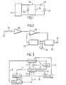
En se reportant à la Fig. 1, on voit que l'étage desortie du stimulateur comprend essentiellement un circuitde charge 21 alimentant la capacité de stimulation 22.Referring to FIG. 1, we see that the floor ofpacemaker output basically includes a
Un interrupteur 25 est susceptible d'assurer ladécharge de la capacité de sortie 26 et de l'interfaceélectrode-coeur 27. Entre la capacité de charge 22 et lereste du circuit est disposé un interrupteur de stimulation28.A
Lorsque la capacité 22 est chargée, l'interrupteurde stimulation 28 est fermé pendant la stimulation, et lacapacité de stimulation 22 se décharge partiellement dansla capacité 26 et dans l'interface coeur-électrode 27.When
Lorsque l'interrupteur 28 s'ouvre, l'interrupteur25 se ferme pendant 12ms, afin de décharger la capacité desortie 26 et l'interface électrode-coeur 27. Pour éviterune saturation, l'amplificateur de détection de la réponsecardiaque 30 (Fig. 2) est déconnecté pendant la durée del'impulsion augmentée de 14 ms, par une occultation connuesous le nom de blanking, et symbolisée par l'interrupteur37.When
Sur la Fig. 2, le signal endocavitaire recueillisur la sonde 31 est amplifié et numérisé par modulationdelta dans une chaíne électronique de mesure comportant un amplificateur 30, un comparateur 32, un compteur-décompteur33, et un convertisseur numérique-analogique 34. Le pas decomptage est appliqué au compteur en 35 et l'état de sortiedu compteur 33 est disponible sous forme de code en 36, etlu par un micro-contrôleur qui réalise tous les calculs.In Fig. 2, the endocavitary signal collectedon
Dans le cadre de l'invention, l'amplitude destimulation est régulée avec un pas de 0,25 V pour lestensions comprises entre 1,25 et 3 V et avec un pas de 0,5V entre 3 V et 5 V.In the context of the invention, the amplitude ofstimulation is regulated with a step of 0.25 V forvoltages between 1.25 and 3 V and with a step of 0.5V between 3 V and 5 V.
Dans certains cas, on commande une contre-stimulationde secours 64ms après une stimulation qui s'estrévélée inefficace. Cette contre-stimulation a une durée,1ms par exemple, supérieure à la durée de la premièrestimulation, 0,5ms par exemple, et une amplitude supérieureà l'amplitude de la première stimulation. La recharge de lacapacité de stimulation ventriculaire 22 est accélérée dèsla délivrance de la première stimulation en suspendant larégulation et la recharge de la capacité de stimulationauriculaire, de façon que l'amplitude de la a tension decharge de la capacité 22, correspondant à la deuxièmestimulation, soit au dessus de la valeur précédente.In some cases, a counter stimulation is orderedemergency response 64ms after stimulationproved ineffective. This counter-stimulation has a duration,1ms for example, greater than the duration of the firststimulation, 0.5 ms for example, and a higher amplitudethe amplitude of the first stimulation. Recharging the
En fonctionnement standard, après chaquestimulation, sauf en cas de stimulation à haute énergieavec une amplitude de 5V, le signal endocavitaire estanalysé pour déterminer l'efficacité de la stimulation,c'est-à-dire pour déterminer si le seuil de capture a étéfranchi. En cas d'inefficacité, les quatre stimulations descycles suivantes sont délivrées à haute énergie.In standard operation, after eachstimulation, except in the case of high energy stimulationwith an amplitude of 5V, the endocavitary signal isanalyzed to determine the effectiveness of the stimulation,that is to say to determine if the catch threshold has beencrossed. In the event of ineffectiveness, the four stimuli of thesubsequent cycles are delivered at high energy.
En fonctionnement standard, et en dehors desstimulations à haute énergie qui ne sont pas prises encompte, les stimulations sont comptabilisées au moyen d'uncompteur-décompteur à 32 pas de comptage. Ce compteur estinitialisé à 31 après chaque recherche de seuil aboutissantà une détermination de la valeur du seuil. A chaquestimulation efficace, le compteur est incrémenté de 1. Achaque stimulation inefficace, le compteur est décrémenté de 4. Lorsque le compteur descend à 0, le stimulateurconsidère le seuil comme erroné et il déclenche une phased'étalonnage. Cette situation correspond à un tauxd'efficacité insuffisant.In standard operation, and outside ofhigh energy stimulations that are not taken into accountaccount, stimuli are counted using aup-down counter with 32 count steps. This counter isinitialized to 31 after each threshold search resultinga determination of the threshold value. Everyeffective stimulation, the counter is incremented by 1. Aeach ineffective stimulation, the counter is decrementedof 4. When the counter drops to 0, the pacemakerconsiders the threshold as incorrect and it triggers a phasecalibration. This situation corresponds to a rateinsufficient efficiency.
Ainsi, une série de huit stimulations inefficacessuccessives, chacune suivie par des stimulations à hauteénergie, déclenche une recherche de seuil.So a series of eight ineffective stimulationssuccessive, each followed by high stimulationenergy, triggers a threshold search.
Pour déterminer si le seuil de capture a étéfranchi, un paramètre peut servir de critère de capture sisa valeur permet de différencier les stimulations efficacesdes stimulations inefficaces, rapidement et de façonfiable. Selon l'invention, le paramètre choisi estl'amplitude négative maximale du signal cardiaque, obtenueaprès le blanking et dans les 64ms suivant la stimulation,par rapport à la ligne de base de ce signal.To determine if the catch threshold has beenpassed, a parameter can serve as a catch criterion ifits value makes it possible to differentiate effective stimulationsineffective stimuli, quickly and in a wayreliable. According to the invention, the parameter chosen isthe maximum negative amplitude of the heart signal, obtainedafter the blanking and within 64 ms following the stimulation,relative to the baseline of this signal.
On a pu observer que la valeur du paramètreaugmente brutalement quand on passe d'une stimulationinefficace à une stimulation efficace, pour une énergie destimulation constante correspondant au seuil d'efficacité.We could observe that the value of the parameterincreases sharply when passing from stimulationineffective at effective stimulation, for an energy ofconstant stimulation corresponding to the efficiency threshold.
Pour les stimulations efficaces, le paramètreaugmente pratiquement linéairement avec l'énergie destimulation, c'est-à-dire avec le carré de la tension, ladurée des impulsions de stimulation étant fixée.For effective stimulation, the parameterincreases practically linearly with the energy ofstimulation, i.e. with the square of the tension, theduration of stimulation pulses being fixed.
Selon l'invention, le paramètre de capture estmesuré et comparé à une valeur de référence pour statuersur l'efficacité de la stimulation. La valeur de référenceest déterminée au cours de la phase d'étalonnage, enrelation avec la Fig. 4, et la mesure du paramètre esteffectuée par soustraction entre la valeur négativemaximale du signal cardiaque et la ligne de base. Le signalendocavitaire amplifié et numérisé par la chaíne de mesurede la Fig. 2, est échantillonné toutes les ms pendant les64ms suivant la stimulation. La ligne de base est obtenueen faisant un échantillon entre 2 et 12ms après lastimulation, pour éviter les éventuels régimes transitoires de stimulation, de décharge de la capacité de sortie, et deblanking.According to the invention, the capture parameter ismeasured and compared to a reference value to decideon the effectiveness of the stimulation. The benchmarkis determined during the calibration phase, inrelationship with Fig. 4, and the parameter measurement isperformed by subtraction between the negative valuemaximum heart rate and baseline. The signalendocavitary amplified and digitized by the measurement chainof Fig. 2, is sampled every ms during64ms following stimulation. The baseline is obtainedby making a sample between 2 and 12 ms after thestimulation, to avoid possible transient regimesstimulation, discharge of exit capacity, andblanking.
Le calcul de l'amplitude négative maximale commenceaprès la fin du blanking et s'arrête 64ms après lastimulation. Le pas de comptage-décomptage est programmé à1, mais si la différence entre deux échantillons successifsest supérieure à 1mV avant amplification, le pas decomptage-décomptage est programmé à 2.Calculation of maximum negative amplitude beginsafter the end of the blanking and stops 64ms after thestimulation. The up / down counting step is programmed at1, but if the difference between two successive samplesis greater than 1mV before amplification, the step ofup-down counting is programmed to 2.
Le suivi automatique du seuil de capture est assuréau moyen d'un algorithme qui comporte deux phasesspécifiques. Tout d'abord une phase d'étalonnage qui permetde déterminer la valeur de référence du paramètre, etensuite une phase de recherche de seuil pour mesurer leseuil d'efficacité.Automatic monitoring of the catch threshold is ensuredusing an algorithm that has two phasesspecific. First a calibration phase which allowsto determine the reference value of the parameter, andthen a threshold research phase to measure theefficiency threshold.
La phase d'étalonnage est lancée à période fixe,par exemple de 24 h en situation chronique et de 6 h ensituation aiguë, à condition que les huit cycles précédentsaient été stimulés à une période supérieure à la périodeminimale augmentée de 32ms. Dans le cas contraire, la phased'étalonnage est différée jusqu'à ce que la condition soitremplie. La phase d'étalonnage est également lancée en casd'insuffisance du taux d'efficacité.The calibration phase is launched at a fixed period,for example 24 hours in chronic situations and 6 hours inacute situation, provided that the previous eight cycleshave been stimulated to a period greater than the periodminimum increased by 32ms. Otherwise, the phaseis deferred until the condition isfilled. The calibration phase is also launched in the eventinsufficient efficiency rate.
La phase de recherche de seuil est automatiquementlancée après chaque étalonnage, et à période fixe, parexemple de 6 h en situation chronique et de 1 h 30 ensituation aiguë, à condition que les huit cycles précédentsaient été stimulés à une période supérieure à la périodeminimale Tmin augmentée de 32ms. Dans le cas contraire,elle est différée jusqu'à ce que la condition soit remplie.The threshold search phase is automaticallylaunched after each calibration, and at a fixed period, byexample of 6 h in chronic situation and 1
A chaque déclenchement de la phase d'étalonnage oude la phase de recherche de seuil, pour éviter le phénomènede fusion, on procède à une réduction de la périodecardiaque de 32 ms, sauf dans le cas où le stimulateurfonctionne en mode DDD avec un délai AV inférieur ou égal à94 ms.Each time the calibration phase is started orof the threshold search phase, to avoid the phenomenonof merger, we proceed to a reduction of the
Le phénomène de fusion se caractérise par lasimultanéité d'une stimulation et d'une dépolarisationcardiaque spontanée.The phenomenon of fusion is characterized by thesimultaneous stimulation and depolarizationspontaneous heart.
Lorsque, au cours de la phase d'étalonnage, lavaleur de référence du paramètre correspond à une valeur deseuil supérieure à 2,5V, la phase de recherche de seuiln'est pas déclenchée.When, during the calibration phase, thereference value of the parameter corresponds to a value ofthreshold greater than 2.5V, the threshold search phaseis not triggered.
Sur le diagramme d'états de la Fig. 3, lesindications ont la signification suivante :
- en cas de seuil valide, l'amplitude et la largeurdes impulsions de stimulation sont optimisées en fonctiondu seuil, et l'efficacité est vérifiée ;
- en cas de seuil inconnu, ou supérieur ou égal à2,5 V, les impulsions de stimulation sont à haute énergie,c'est-à-dire qu'elles ont une amplitude de 5 V et unelargeur de 0,5 ms à 1ms ;
- in the event of a valid threshold, the amplitude and the width of the stimulation pulses are optimized as a function of the threshold, and the effectiveness is verified;
- in the event of an unknown threshold, or greater than or equal to 2.5 V, the stimulation pulses are high energy, that is to say that they have an amplitude of 5 V and a width of 0.5 ms at 1ms;
Les changements d'états mentionnés sur la Fig. 3correspondent respectivement à :
En fonctionnement standard, la stimulation estréalisée avec une amplitude calculée de manière à avoir unemarge de sécurité supérieure ou égale à 100% par rapport auseuil d'efficacité. On mesure donc le seuil et on calculel'amplitude de l'impulsion de stimulation au moins audouble de la valeur de seuil. De plus, le seuil esttoujours mesuré avec des impulsions dont la largeur est de0,5ms. Dans le tableau récapitulatif, les valeurs de seuilsont indiquées avec un pas de 0,25V, et les amplitudescorrespondantes de l'impulsion de stimulation avec un pasde 0,5VIn standard operation, stimulation isperformed with an amplitude calculated so as to have asafety margin greater than or equal to 100% compared toefficiency threshold. So we measure the threshold and calculatethe amplitude of the stimulation pulse at least atdouble the threshold value. In addition, the threshold isalways measured with pulses whose width is0.5ms. In the summary table, the threshold valuesare indicated with a step of 0.25V, and the amplitudesof the stimulation pulse with one step0.5V
La dernière ligne du tableau récapitulatifcorrespond aux impulsions de stimulation de haute énergie, dont la durée est comprise entre 0,5 et 1ms, et depréférence égale à 0,5ms.The last line of the summary tablecorresponds to high energy stimulation pulses,whose duration is between 0.5 and 1 ms, andpreferably equal to 0.5 ms.
Lorsque le seuil est inférieur à 2,5V, l'efficacitéde chaque stimulation à l'amplitude optimale correspondantau tableau est vérifiée. Si une stimulation est inefficace,le programme prévoit que les stimulations des quatre cyclescardiaques suivants sont des stimulations de haute énergie.When the threshold is lower than 2.5V, the efficiencyof each stimulation to the corresponding optimal amplitudeon the board is checked. If stimulation is ineffective,the program foresees that the stimulations of the four cyclesThe following cardiac stimuli are high energy.
Le taux d'efficacité de stimulation est évalué, etle seuil est considéré comme erroné lorsque le compteur destimulations, descend à 0. Chaque stimulation efficaceapplique au compteur un incrément de 1, chaque stimulationinefficace applique au compteur un décrément de 4. Lorsquele compteur est à 0, le taux d'efficacité de stimulationest considéré comme insuffisant.The stimulation efficiency rate is evaluated, andthe threshold is considered erroneous when thestimulation, drops to 0. Each effective stimulationapplies an increment of 1 to the counter, each stimulationineffective applies a decrement of 4 to the meter.the counter is at 0, the stimulation efficiency rateis considered insufficient.
Le programme commande un étalonnage avec unepériodicité déterminée, qui est par exemple de 24 heures ensituation chronique et de 6 heures en situation aiguë, etchaque fois que le taux d'efficacité des stimulations estinsuffisant.The program commands a calibration with adetermined periodicity, which is for example 24 hours inchronic situation and 6 hours in acute situation, andwhenever the stimulation rate isinsufficient.
Dans le cas où le seuil est considéré comme erronéou inconnu, les stimulations sont programmées à hauteénergie, puis un étalonnage et une recherche de seuil sontdéclenchés.In the event that the threshold is considered to be incorrector unknown, the stimulations are programmed at highenergy and then a calibration and a threshold search aretriggered.
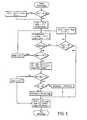
La phase d'étalonnage est décrite en relation avecle diagramme de la Fig. 5 (mode VVI) ou de la Fig. 6 (modeDDD).The calibration phase is described in relation tothe diagram in FIG. 5 (VVI mode) or of Fig. 6 (modeDDD).
L'étalonnage commence après réduction de 32 ms,pour éviter la fusion, soit de l'intervalle d'échappementIE (Fig. 5) en mode VVI, soit du délai AV (Fig. 6) en modeDDD. Si cette réduction n'est pas possible : en mode VVI,on attend que la réduction soit devenue possible, et enmode DDD, on procède à l'étalonnage sans réduction du délaiAV.The calibration starts after reduction of 32 ms,to avoid merging either the escape intervalIE (Fig. 5) in VVI mode, or AV delay (Fig. 6) in modeDDD. If this reduction is not possible: in VVI mode,we wait until the reduction has become possible, andDDD mode, calibration is carried out without delay reductionAV.
L'étalonnage consiste à déterminer, pour lesstimulations efficaces, la droite représentative duparamètre de capture (Fig. 4) en fonction du carré de l'amplitude de stimulation, qui constitue une image del'énergie de stimulation.The calibration consists in determining, for theeffective stimulations, the line representative of thecapture parameter (Fig. 4) as a function of the square ofthe amplitude of stimulation, which constitutes an image ofstimulation energy.
La détermination de cette droite permet de fixer lalimite de la région d'efficacité.The determination of this straight line makes it possible to fix thelimit of the efficiency region.
La droite est déterminée par deux pointscorrespondant respectivement aux amplitudes de stimulation2,5V et 5V, avec une durée de 0,5ms. Après chaquestimulation à 2,5V, une contre-stimulation de sécurité à1ms est déclenchée pour le cas où le seuil excéderait 2,5V.The line is determined by two pointscorresponding respectively to the stimulation amplitudes2.5V and 5V, with a duration of 0.5ms. After each2.5V stimulation, a safety counter-stimulation at1ms is triggered in case the threshold exceeds 2.5V.
Pour chacune des deux amplitudes, une série dequatre stimulations est réalisée et le programme assure lamesure du paramètre et sa moyenne :P2 pour l'amplitude2,5V; P5 pour l'amplitude 5V.For each of the two amplitudes, a series offour stimulations are performed and the program ensures themeasurement of the parameter and its mean: P2 for the amplitude2.5V; P5 for 5V amplitude.
Dans le cas de l'amplitude 5V, avant la série dequatre stimulations, le programme déclenche sixstimulations afin de stabiliser la charge de la capacité destimulation, ce qui est souhaitable lorsque la pile est enservice depuis longtemps.In the case of the 5V amplitude, before the series offour stimulations, the program triggers sixstimulations in order to stabilize the load of the ability tostimulation, which is desirable when the battery is inservice for a long time.
Lorsque les quatre valeurs du paramètre de capturesont dispersées, c'est-à-dire leur écart relatif important,le programme considère qu'elles ne sont pas cohérentes. Sila période du cycle cardiaque n'est pas supérieure à lapériode minimale autorisée Tmin augmentée de 32 ms (en modeVVI), ou si le délai AV n'est pas supérieur à 94 ms (enmode DDD), le programme sort de la phase d'étalonnage. Sila période du cycle cardiaque est supérieure à la périodeminimale autorisée Tmin augmentée de 32 ms et si lestimulateur fonctionne en mode VVI, l'intervalled'échappement IE ventriculaire est diminué de 32ms et unenouvelle série de quatre stimulations est déclenchée. Si lestimulateur fonctionne en mode DDD et si le délai auriculo-ventriculaireest supérieur à 94 ms, le délai AV est réduitde 32 ms et une nouvelle série de quatre stimulations estdéclenchée. Cette opération est réalisée pour des séries dequatre impulsions dont le nombre N est, au maximum, égal à 3. Si les valeurs du paramètre sont toujours noncohérentes, le programme sort de la phase d'étalonnage.When the four values of the capture parameterare dispersed, i.e. their significant relative deviation,the program considers that they are not consistent. Yesthe period of the cardiac cycle is not greater than theminimum authorized period Tmin increased by 32 ms (in modeVVI), or if the AV delay is not more than 94 ms (inDDD mode), the program exits the calibration phase. Yesthe period of the cardiac cycle is greater than the periodminimum allowed Tmin increased by 32 ms and if thepacemaker works in VVI mode, the intervalventricular IE exhaust is decreased by 32ms and anew series of four stimulations is triggered. If thepacemaker works in DDD mode and if the atrioventricular delayis greater than 94 ms, the AV delay is reducedof 32 ms and a new series of four stimulations istriggered. This operation is carried out for series offour pulses whose number N is, at most, equal to3. If the parameter values are still noconsistent, the program exits the calibration phase.
Les valeurs moyennes du paramètre de captureobtenues pour les amplitudes 5V et 2,5V permettent lecalcul de la pente a et de l'ordonnée à l'origine b de ladroite (y = ax + b) représentative du paramètre en fonctiondu carré de l'amplitude (Fig. 4).The average values of the capture parameterobtained for the amplitudes 5V and 2.5V allow thecalculation of the slope a and the ordinate at the origin b of theline (y = ax + b) representative of the parameter as a functionthe square of the amplitude (Fig. 4).
Le programme fixe alors la valeur de référence edu paramètre de capture par exemple, aux trois quarts de lavaleur b, de façon à éliminer les stimulations inefficacesconsidérées comme efficaces. L'erreur contraire consistantà considérer comme inefficace une stimulation efficacen'est pas préjudiciable.The program then fixes the reference value eof the capture setting for example, three quarters of thevalue b, so as to eliminate ineffective stimuliconsidered effective. Consistent errorto consider effective stimulation as ineffectiveis not harmful.
Dans le cas où la dispersion des mesures conduit àune pente négative pour la droite, le programme considèrela pente comme nulle et prend pour valeur b la moyenne desvaleurs du paramètre pour les deux amplitudes destimulation (Pmoy).In the event that the dispersion of the measurements leads toa negative slope for the right, the program considersthe slope as zero and takes as value b the average ofparameter values for the two amplitudes ofstimulation (Pmoy).
Dans le cas où la valeur b calculée est trèsfaible ou négative, le programme considère que le seuil estsupérieur à 2,5 V : la valeur de référence du paramètren'est pas calculée et des stimulations à haute énergie sontprévues.In case the calculated b value is veryweak or negative, the program considers that the threshold isgreater than 2.5 V: the reference value of the parameteris not calculated and high energy stimulations areprovided.
Pendant le déroulement de la phase d'étalonnage, ladétection d'un complexe spontané provoque le report de lastimulation au cycle cardiaque suivant. La 32ème détectionprovoque l'arrêt de la phase d'étalonnage et sa suspensionjusqu'à l'occurrence de huit cycles stimulés consécutifs.During the course of the calibration phase, thedetection of a spontaneous complex causes the postponement of thestimulation to the next cardiac cycle. The 32nd detectioncauses the calibration phase to stop and its suspensionuntil the occurrence of eight consecutive stimulated cycles.
Lorsque la phase d'étalonnage définit pour le seuilune valeur supérieure à 2,5 V, la phase de recherche deseuil n'est pas déclenchée.When the calibration phase defines for the thresholda value greater than 2.5 V, the search phase ofthreshold is not triggered.
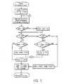
Après la phase d'étalonnage, le programme lance laphase de recherche de seuil correspondant au diagramme dela Figure 7 (mode VVI) ou de la Fig. 8 (mode DDD).After the calibration phase, the program starts thethreshold search phase corresponding to theFigure 7 (VVI mode) or Fig. 8 (DDD mode).
Le seuil d'efficacité est recherché avec des sériesde quatre impulsions de largeur 0,5 ms et dont l'amplitudevarie à chaque série, de 2,25 V à 1,25 V.The efficiency threshold is sought with seriesfour pulses of width 0.5 ms and whose amplitudevaries with each series, from 2.25 V to 1.25 V.
Entre chaque série de quatre impulsions,l'amplitude est réduite de 0,25 V.Between each series of four pulses,the amplitude is reduced by 0.25 V.
L'efficacité est déterminée pour chaquestimulation. Lorsqu'une stimulation est inefficace, unecontre-stimulation de 1 ms est déclenchée à la fin du délaide 64 ms.Efficacy is determined for eachstimulation. When stimulation is ineffective, a1 ms counter stimulation is triggered at the end of the delayof 64 ms.
Après chaque série de quatre stimulations à mêmeénergie, trois cas se présentent :
Si la période du cycle cardiaque est supérieureà la période minimale augmentée de 32 ms et si lestimulateur est en mode VVI, l'intervalle d'échappementventriculaire IE est diminué de 32 ms pour réduire lerisque de fusion, et une série de quatre impulsions estdéclenchée avec la même amplitude. Le nombre de réductionsde IE est, dans ce cas, limité à trois.If the period of the cardiac cycle is longerat the minimum period increased by 32 ms and if thepacemaker is in VVI mode, the escape intervalventricular IE is decreased by 32 ms to reduce therisk of fusion, and a series of four pulses istriggered with the same amplitude. The number of reductionsof IE is, in this case, limited to three.
Si le stimulateur est en mode DDD est si le délaiAV est supérieur à 94 ms, ce délai AV est réduit de 32 mset une série de quatre impulsions est déclenchée avec lamême amplitude. Le nombre de réductions du délai AV est,dans ce cas, limité à trois.If the pacemaker is in DDD mode is if the delayAV is greater than 94 ms, this AV delay is reduced by 32 msand a series of four pulses is triggered with thesame amplitude. The number of AV delay reductions is,in this case, limited to three.
Sinon, la valeur retenue pour le seuil est celle del'amplitude précédente.Otherwise, the value used for the threshold is that ofthe previous amplitude.
Au cours de la phase de recherche de seuil, ladétection d'un complexe spontané provoque le report de lastimulation au cycle cardiaque suivant, et la 32èmedétection provoque l'arrêt de la recherche de seuil jusqu'àl'occurrence de huit cycles stimulés consécutifs.During the threshold search phase, thedetection of a spontaneous complex causes the postponement of thestimulation to the next cardiac cycle, and the 32nddetection causes the threshold search to stop untilthe occurrence of eight consecutive stimulated cycles.
Après détermination du seuil de capture, leprogramme prévoit la définition de l'amplitude F1 del'impulsion de stimulation selon le tableau récapitulatifprécédent.After determining the catch threshold, theprogram provides for the definition of the F1 amplitude ofthe stimulation pulse according to the summary tableprevious.
Le procédé selon l'invention est de préféfence,exécuté par un dispositif à microprocesseur possédant desinstructions de logiciel programmées pour exécuter lesétapes de procédé décrites plus haut.The process according to the invention is preferably,executed by a microprocessor device havingsoftware instructions programmed to execute theprocess steps described above.
L'élaboration du logiciel adéquat pour contrôlerdes stimulateurs cardiaques contrôlés par microprocesseurpeut être effectuée par un homme du métier de compétenceordinaire. Bien entendu, il est également possible demettre en oeuvre la présente invention au moyen de circuitsanalogiques ou numériques de type connu.Developing the right software to controlmicroprocessor-controlled pacemakerscan be performed by a skilled personordinary. Of course, it is also possible toimplementing the present invention by means of circuitsanalog or digital of known type.
Grâce à l'invention, le réglage de l'énergie destimulation ventriculaire selon l'invention permetd'adapter automatiquement et périodiquement l'énergie destimulation aux besoins du patient.Thanks to the invention, the adjustment of the energy ofventricular pacing according to the invention allowsautomatically and periodically adapt the energy ofstimulation to the patient's needs.
Les avantages de la présente invention sont enparticulier :
- une plus grande sécurité pour le patient car lestimulateur s'adapte à l'évolution du seuil de capture ;
- une diminution des contraintes pour le médecinqui n'a plus à effectuer de test préalable ni de réglagedes paramètres de stimulation ;
- une réduction de la consommation d'énergie,c'est-à-dire une réduction de la taille de la pile et/ouune augmentation de sa durée de vie.
- greater safety for the patient because the stimulator adapts to changes in the capture threshold;
- a reduction in constraints for the doctor who no longer has to carry out a preliminary test or adjust the stimulation parameters;
- a reduction in energy consumption, that is to say a reduction in the size of the battery and / or an increase in its lifespan.
L'invention relative au réglage de l'énergie destimulation s'applique à un stimulateur simple chambre, oudouble chambre comportant une stimulation ventriculaireavec amplitude régulée et une détection ventriculaire avecun amplificateur à récupération rapide pour détecter laréponse cardiaque.The invention relating to the regulation of the energy ofstimulation applies to a single chamber pacemaker, ordouble chamber with ventricular stimulationwith regulated amplitude and ventricular detection witha quick recovery amplifier to detect thecardiac response.
Les valeurs numériques sont données à titred'exemple dans la description qui précède : elles sontsusceptibles d'adaptation et n'ont aucun caractèrelimitatif.Numerical values are given asexample in the above description: they aresusceptible of adaptation and have no characterlimiting.
Les avantages du réglage de l'énergie destimulation selon l'invention sont notamment les suivants:
- l'utilisation d'une sonde classique, unipolaireou bipolaire, car l'invention fonctionne quel que soit letype de sonde ;
- une polarité pour la détection de la capture quiest la même que la polarité de détection (on entend parpolarité le caractère unipolaire ou bipolaire de la sonde);
- l'absence de commutation, ou de modification descaractéristiques de l'amplificateur ;
- l'absence d'application de charge opposée à lacharge de stimulation, et la simple décharge de la capacitéde sortie pendant un intervalle de temps de 12 ms ;
- la détection de la capture dans un délai de 14 à64 ms après la stimulation ;
- l'application d'une contre-stimulation 64 msaprès la stimulation, en cas de stimulation inefficace,pendant la phase d'étalonnage et pendant la phase derecherche de seuil ;
- l'application de l'invention aussi bien au cas dela stimulation ventriculaire (mode VVI) qu'au cas de lastimulation auriculaire (mode AAI).
- the use of a conventional probe, unipolar or bipolar, because the invention works regardless of the type of probe;
- a polarity for the detection of the capture which is the same as the detection polarity (the polarity is understood to be the unipolar or bipolar character of the probe);
- the absence of switching, or of modification of the characteristics of the amplifier;
- the absence of application of charge opposite to the stimulation charge, and the simple discharge of the output capacity during a time interval of 12 ms;
- detection of the capture within 14 to 64 ms after the stimulation;
- the application of a counter-stimulation 64 ms after the stimulation, in the event of ineffective stimulation, during the calibration phase and during the threshold search phase;
- the application of the invention both in the case of ventricular stimulation (VVI mode) and in the case of atrial stimulation (AAI mode).
Par ailleurs, dans l'exemple de la Fig. 4, on aretenu pour simplifier le cas d'une caractéristique droite.Le procédé est aussi applicable au cas d'unecaractéristique courbe en prenant plusieurs points pour la phase d'étalonnage, et retenir pour valeur de b l'ordonnéeà l'origine de la courbe extrapolée.Furthermore, in the example of FIG. 4, we haveretained to simplify the case of a straight characteristic.The method is also applicable in the case of acharacteristic curve taking several points for thecalibration phase, and keep the ordinate for value of bat the origin of the extrapolated curve.
Claims (48)
- A method of regulating, by means of software, the pacing energy ina cardiac pacemaker by measurement of a capture parameter, comprisingthe following steps:a capture parameter is defined constituted by the maximumnegative amplitude of the cardiac signal obtained after pacing, within adetermined period, as a function of the pacing energy;the representative characteristics of the capture parameter as afunction of the pacing energy are determined during a calibration phase;a reference value for determining the effectiveness of the pacingoperations is defined from these characteristics;the capture threshold value is determined from the reference valueduring a threshold search phase;and the pacing energy is determined as a function of the value ofthe capture threshold.
- A method according to Claim 1,characterised in that thedetermined period starts after the blanking and ends approximately 64 msafter the pacing operation.
- A method according to Claim 1,characterised in that in the eventthat the capture parameter varies linearly as a function of the pacingenergy, the characteristics of the straight line representative of thecapture parameter are the slope (a) and the ordinate at the origin (b).
- A method according to Claim 3,characterised in that the referencevalue for determining the effectiveness of the pacing operations is afraction of the ordinate at the origin (b) preferably equal to 3/4.
- A method according to Claim 1,characterised in that at the start ofthe calibration phase or of the threshold search phase, if possible theperiod of the cardiac cycle is reduced so as to avoid the phenomenon offusion.
- A method according to Claim 1,characterised in that fordetermining the value of the capture threshold, successive series ofstimulus pulses are produced by decreasing the amplitude of the pulsesbetween the series.
- A method according to Claim 6,characterised in that each series ofpulses is preferably constituted of four pulses of the same amplitude.
- A method according to Claim 6,characterised in that, after eachseries of stimulus pulses which have all been effective, the amplitude isreduced by a determined quantity, preferably 0.25 volts.
- A method according to Claim 8,characterised in that, when theamplitude of the stimulus pulses is of the order of 1.25 volts, this value isretained as threshold value.
- A method according to Claim 6,characterised in that, after a seriesof stimulus pulses which are all ineffective, the amplitude of the pulses ofthe previous series is defined as threshold value.
- A method according to Claim 6,characterised in that, if thepacemaker is operating in VVI mode, after a series of stimulus pulseswhich do not all yield the same result, it is determined whether the periodof the cardiac cycle is greater by at least one duration of approximately 32ms than the minimum permitted period:in that case, the ventricularescape interval is reduced by said duration and a new series of stimuluspulses with the same amplitude is carried out, and in the opposite case the amplitude of the stimulus pulses of the previous series is defined asthreshold value.
- A method according to Claim 6,characterised in that, if thepacemaker is operating in DDD mode, after a series of stimulus pulseswhich do not all yield the same result, it is determined whether the AVdelay is greater by at least one duration of approximately 32 ms than avalue preferably equal to 62 ms:in that case, the AV delay is reduced bysaid duration, and a new series of stimulus pulses with the sameamplitude is carried out, and in the contrary case the amplitude of thestimulus pulses of the previous series is defined as threshold value.
- A method according to Claim 1,characterised in that the pacingenergy is determined by taking as the amplitude of the stimulus pulsestwice the value of the capture threshold.
- A method according to Claim 1,characterised in that, during thecalibration phase, after each pacing operation at 2.5 volts, a counter-pacingoperation is triggered.
- A method according to Claim 1,characterised in that, during thethreshold search phase, in the event of an ineffective pacing operation, acounter-pacing operation is triggered.
- A method according to Claim 1,characterised in that, outside thecalibration and threshold search phases, except in the event of a high-energypacing operation, the effectiveness of each pacing operation is determined, andin the event of a pacing operation which is ineffective, the pacing operations ofthe following cycles, preferably four in number, are delivered with high energy.
- A method according to Claim 1,characterised in that the effectiveness ofthe pacing operations is evaluated by means of a reversible counter to whichthere is applied an increment of 1, preferably, for each effective pacingoperation, and a decrement of 4, preferably, for each ineffective pacing operation, and when the counter returns to 0, the effectiveness of the pacingoperations is defined as insufficient, and a calibration phase is triggered.
- A method according to Claim 1,characterised in that during thecalibration phase the coherence of the series of pacing operations is preferablychecked at most three times.
- A method according to one of Claims 11 or 12,characterised in that,during the threshold search phase, preferably the cardiac period is reducedat most three times to determine the effectiveness of the pacing operations.
- A method according to Claim 1,characterised in that a chronicsituation and an acute situation are distinguished corresponding to a periodof approximately one month from implantation of the pacemaker.
- A method according to Claim 20,characterised in that the periodicityof the calibration phases is 24 hours in a chronic situation and 6 hours in anacute situation.
- A method according to Claim 20,characterised in that the periodicity ofthe threshold search phases is 6 hours in a chronic situation and 1 hour 30 min.in an acute situation.
- A method according to Claim 1,characterised in that, when thecalibration phase defines a value greater than 2.5 volts for the threshold, thethreshold search phase is not triggered.
- A method according to Claim 1 for regulating the pacing energy of astimulus pulse having an amplitude and a width for pacing, delivered by acardiac pacemaker,characterised by the following steps:monitoring the endocardial signals in response to said stimulus pulsedelivered by the pacemaker and providing a response value representativeof the endocardial response;defining the capture threshold corresponding to a minimum stimuluspulse energy producing a desired value of endocardial response;regulating the stimulus pulse energy corresponding to the defined valueof the capture threshold;defining that a delivered stimulus pulse is effective if the endocardialresponse value provided is greater than the defined capture threshold, andineffective if the endocardial response value provided is less than the definedcapture threshold, andproducing a selected number of high-energy stimulus pulses inresponse to a stimulus pulse which is defined as ineffective.
- A method according to Claim 24,characterised in that furthermore: acount of the effective and ineffective stimulus pulses is kept, the count isincremented each time the stimulus pulse provided is effective; the count isdecremented each time the stimulus pulse provided is ineffective; and a newcapture threshold is defined in response to a reduction in the count to apredetermined count value.
- A method according to Claim 25,characterised in that an increment ofone is applied to the count for each stimulus pulse which is defined aseffective up to a maximum value of the count and a decrement of four isapplied for each stimulus pulse which is defined as ineffective, andin thatsaid predetermined count value is zero.
- A method according to Claim 24,characterised in that the definition ofthe capture threshold furthermore comprises the following steps:producing a plurality of calibrating stimulus pulses having a determinedamplitude and width;determining whether or not the calibrating stimulus pulses areeffective;adjusting the amplitude of the calibrating stimulus pulses to identifythe minimum pulse amplitude for the given width corresponding to aneffective stimulus pulse, anddefining the capture threshold from the identified minimumamplitude of the calibrating stimulus pulses.
- A method according to Claim 24,characterised in that the definitionof the capture threshold furthermore comprises the following steps:ID 2057 0 1. producing a series of a first number of calibrating stimuluspulses having a determined amplitude and width;ii. determining whether each pulse of the first number of pulses of theseries produced is effective, andiii. in response to the fact that each pulse of the first number of pulsesof the series is effective,a) reducing the amplitude of the calibrating stimulus pulse by apredetermined quantity and producing another series of the first number ofcalibrating stimulus pulses at the reduced pulse amplitude;b) determining whether each pulse of the first number of pulses of theseries produced is effective;c) in response to the fact that each pulse of the first number of pulses isineffective, defining the capture threshold as being the amplitude of thecalibrating stimulus pulses of the previous series, and,d) in response to the fact that a pulse of the first number of pulses of theseries is effective, recommencing step iii.
- A method according to Claim 28,characterised in that the first numberof pulses is four, andin that each pulse has the same width and the sameamplitude.
- A method according to Claim 28,characterised in that the pulse width isselected between 0.5 ms and 1.0 ms and the quantity determined is selectedbetween 0.25 and 0.5 volts.
- A method according to Claim 24,characterised in that the definition ofthe capture threshold comprises: a step consisting of maintaining the defined capture threshold at a value equal to or greater than a minimum capturethreshold corresponding to a minimum amplitude and pulse width.
- A method according to Claim 28, in which the pacemaker operates inVVI mode with a ventricular escape interval and a cardiac cycle,characterisedin that step ii. furthermore comprises: determining whether the series ofstimulus pulses comprises at least one effective calibrating stimulus pulse andone ineffective calibrating stimulus pulse, and, in response, determiningwhether the period of the cardiac cycle analysed is greater by at least one firstduration than a determined minimum period , and, in this case, reducing theventricular escape interval by the first duration and recommencing steps i-iiiwith calibrating stimulus pulses with the same amplitude as the previousseries and, in the opposite case, defining the capture threshold value as beingthe amplitude of the pulses of the previous series.
- A method according to Claim 28, in which the pacemaker operates inDDD mode with an AV delay,characterised in that step ii. furthermorecomprises: determining whether the first series of calibrating stimulus pulsescomprises at least one effective pulse and at least one ineffective pulse, and,in response, determining whether the AV delay is greater by at least one firstquantity than a predetermined value and,in that case, reducing the AV delayby the first quantity and recommencing steps i-iii with calibrating stimuluspulses at the same pulse amplitude as in the previous cycle, and, in theopposite case, defining the capture threshold value as being the amplitude ofthe pulses of the previous series.
- A method according to Claim 24,characterised in that the step ofdefining the capture threshold furthermore comprises: the determination of anew capture threshold at a periodicity of approximately 24 hours in a chronicsituation and approximately 6 hours in an acute situation.
- A method according to Claim 24,characterised in that the step ofdefining the capture threshold furthermore comprises:defining a capture parameter which varies as a function of thepacing energy;providing a calibration phase for determining representativecharacteristics of the capture parameter as a function of the analysedendocardial response to one or more calibrating stimulus pulses;defining a reference value for determining the effectiveness ofcalibrating stimulus pulses in response to the determined representativecharacteristics of the capture parameter; andproviding a threshold search phase for determining the value ofthe capture threshold relative to the defined reference value.
- A device for regulating the pacing energy in a cardiac pacemaker,comprising:characterised in that it comprises means for defining the capturethreshold according to a calibration process in which representativecharacteristics of a capture parameter constituted by the maximum negativeamplitude of the cardiac signal obtained after pacing within a determined periodare determined as a function of the pacing energy analysed in response to oneor more pulses, the capture parameter varying as a function of the pacingenergy, and in which a reference value is defined to determine theeffectiveness of a pulse in response to the determined representativecharacteristics of the capture parameter, and according to a threshold searchprocess in which the value of the capture threshold is determined on the basisof the defined reference value.a pulse generator for producing pulses having a determinedpacing energy,a monitor for sensing the endocardial response to the pacingenergy of a delivered pulse,means for controlling the pacing energy provided relative to adetermined capture threshold value,
- A device according to Claim 36 for regulating the pacing energy ofstimulus pulses delivered by a cardiac pacemaker,characterised in that:andin that it comprises:the generator produces stimulus pulses having an amplitude anda width which can be defined and correspond to a pacing energy;the monitor senses the endocardial response to the stimuluspulses delivered by the pacemaker and provides a response valuerepresentative of the endocardial response;means for defining the capture threshold to correspond to theminimum stimulus pulse energy producing a determined value of endocardialresponse, andmeans for determining that the stimulus pulse delivered iseffective when the value of the endocardial response is greater than thedefined capture threshold and ineffective when the provided value of theendocardial response is less than the defined capture threshold, such that thecontrol means cause the generator to produce a determined number ofstimulus pulses having a determined amplitude and width corresponding to ahigh-energy pulse in response to a stimulus pulse which is defined asineffective.
- A device according to Claim 37,characterised in that it furthermorecomprises: a counter for keeping a count of the effective and ineffectivestimulus pulses, the counter being incremented when the stimulus pulsedelivered is effective and decremented when the stimulus pulse delivered isineffective, such that the definition means define a new capture thresholdwhen the counter drops to a predetermined count value.
- A device according to Claim 38,characterised in that the counter isincremented by one for each stimulus pulse which is determined as effectiveup to a maximum count value, and decremented by four for each stimuluspulse which is determined as ineffective, andin that the predetermined countvalue is zero.
- A device according to Claim 37,characterised in that the definitionmeans furthermore comprise: means acting on the generator to produce aplurality of calibrating stimulus pulses having a determined amplitude and width; a comparator for determining whether or not the calibrating stimuluspulses are effective: such that the means acting on the generator adjust theamplitude of the calibrating stimulus pulses to identify the minimum pulseamplitude corresponding to an effective stimulus pulse for a given pulse width;and that the definition means define the capture threshold from the identifiedminimum amplitude of the calibrating stimulus pulses.
- A device according to Claim 37,characterised in that the definitionmeans furthermore comprise:means acting on the generator to produce a series of a firstnumber of calibrating stimulus pulses having a determined amplitude andwidth;means for determining whether each of the first number ofpulses of the series generated is effective, such that, in response to the factthat each pulse of the first number is effective, the acting means make thegenerator produce a series of calibrating stimulus pulses having an amplitudereduced by a predetermined quantity relative to the pulse amplitude of theprevious series, and the determination means determine whether each of thefirst number of pulses of the series generated is effective, and such that, inresponse to the fact that each of the first number of pulses is ineffective, thedefinition means define the capture threshold as being the amplitude of thecalibrating stimulus pulses of the previous series of pulses; and such that theacting means, in response to the fact that one of the first number of pulses iseffective, cause the generator and the determination means to continue toproduce successive series of pulses of increasingly reduced amplitude untilthe definition means define a capture threshold.
- A device according to Claim 41,characterised in that the first number ofpulses is four, andin that each pulse of the same series has the same widthand the same amplitude.
- A device according to Claim 42,characterised in that the pulse width isselected between 0.5 ms and 1.0 ms and the predetermined quantity isselected between 0.25 and 0.5 volts.
- A device according to Claim 37,characterised in that the definitionmeans furthermore comprise a comparator for comparing the provided valueof the endocardial response with a determined minimum capture threshold,and for providing the capture threshold at the minimum value determined if theprovided value of the endocardial response is not greater than the determinedminimum value.
- A device according to Claim 41, in which the pacemaker operates inVVI mode with a ventricular escape interval,characterised in that itfurthermore comprises:first means for determining whether the calibrating stimulus pulses ofthe series produce at least one effective calibrating stimulus pulse and oneineffective calibrating stimulus pulse;second means for determining whether the period of an analysedcardiac cycle is greater by at least one first duration than a determinedminimum period; andmeans for reducing the ventricular escape interval by a first duration inresponse to calibrating stimulus pulses producing at least one effectivestimulus pulse and one ineffective pulse when the measured cardiac cycle isgreater by at least one first duration than the determined minimum period,such that, in response to a reduction in the ventricular escape interval, themeans acting on the generator cause the generator to produce a series ofcalibrating stimulus pulses of a pulse amplitude identical to that of theprevious series, and, in response to the absence of a reduction in theventricular escape interval, the definition means define the threshold value asequal to the amplitude of the calibrating stimulus pulses of the previous series.
- A device according to Claim 41, in which the pacemaker operates inDDD mode with an AV delay,characterised in that it furthermore comprises:first means for determining whether the series produces at leastone effective calibrating stimulus pulse and one ineffective calibratingstimulus pulse;means for determining whether the AV delay is greater by a firstquantity than a determined value; andmeans for reducing the AV delay by the first quantity in theevent that the AV delay is greater by the first quantity than the determinedvalue, such that, in response to a reduction in the AV delay, the meansacting on the generator cause the generator to produce a series ofcalibrating stimulus pulses of an amplitude identical to that of the previousseries, and, in response to the absence of a reduction in the AV delay, thedefinition means define the threshold value as equal to the amplitude of thecalibrating stimulus pulses of the previous series.
- A device according to Claim 37,characterised in that the definitionmeans periodically define a new capture threshold at a periodicity ofapproximately 24 hours in a chronic situation and approximately 6 hours inan acute situation.
- A device according to Claim 37,characterised in that the definitionmeans furthermore comprise means for determining the capture thresholdaccording to a calibration process, such that representative characteristics ofa capture parameter are determined as a function of the analysedendocardial response to one or more calibrating stimulus pulses, the captureparameter varying as a function of the pacing energy, and such that areference value is defined to determine the effectiveness of the stimuluspulses in response to the determined representative characteristics of thecapture parameter; and according to a threshold search process, such thatthe value of the capture threshold is determined on the basis of thedetermined reference value.
Applications Claiming Priority (3)
| Application Number | Priority Date | Filing Date | Title |
|---|---|---|---|
| FR9110169AFR2680093B1 (en) | 1991-08-09 | 1991-08-09 | METHOD FOR CONTROLLING THE STIMULATION ENERGY IN A HEART STIMULATOR. |
| FR9110169 | 1991-08-09 | ||
| PCT/FR1992/000779WO1993002741A1 (en) | 1991-08-09 | 1992-08-07 | Method and device for checking stimulation power in a pacemaker |
Publications (2)
| Publication Number | Publication Date |
|---|---|
| EP0552357A1 EP0552357A1 (en) | 1993-07-28 |
| EP0552357B1true EP0552357B1 (en) | 2003-12-17 |
Family
ID=9416089
Family Applications (1)
| Application Number | Title | Priority Date | Filing Date |
|---|---|---|---|
| EP92918047AExpired - LifetimeEP0552357B1 (en) | 1991-08-09 | 1992-08-07 | Method and device for checking stimulation power in a pacemaker |
Country Status (5)
| Country | Link |
|---|---|
| US (1) | US5411533A (en) |
| EP (1) | EP0552357B1 (en) |
| DE (1) | DE69233272T2 (en) |
| FR (1) | FR2680093B1 (en) |
| WO (1) | WO1993002741A1 (en) |
Families Citing this family (53)
| Publication number | Priority date | Publication date | Assignee | Title |
|---|---|---|---|---|
| US5350410A (en)* | 1992-11-23 | 1994-09-27 | Siemens Pacesetter, Inc. | Autocapture system for implantable pulse generator |
| DE4416779B4 (en)* | 1994-05-09 | 2007-06-06 | Biotronik Meß- und Therapiegeräte GmbH & Co. Ingenieurbüro Berlin | Device for avoiding the temporal coincidence of stimulated and spontaneous cardiac reactions |
| US5713933A (en)* | 1994-11-30 | 1998-02-03 | Medtronic, Inc. | Method and apparatus for automatic pacing threshold determination |
| US5674254A (en)* | 1995-05-22 | 1997-10-07 | Vitatron Medical, B.V. | Cardiac pacemaker system and method for determining a measure of pacing threshold without incurring loss of capture |
| FR2739783B1 (en) | 1995-10-13 | 1998-01-23 | Ela Medical Sa | DEFIBRILLATOR / ACTIVE IMPLANTABLE CARDIOVERVER MEDICAL DEVICE WITH HEADSET DEFIBRILLATION |
| US5954754A (en)* | 1997-05-05 | 1999-09-21 | Vitatron Medical, B.V. | Single pass lead dual chamber pacing system with means for evaluating efficiency of atrial pacing |
| US5855594A (en)* | 1997-08-08 | 1999-01-05 | Cardiac Pacemakers, Inc. | Self-calibration system for capture verification in pacing devices |
| FR2774916B1 (en) | 1998-02-13 | 2000-06-16 | Ela Medical Sa | ACTIVE IMPLANTABLE MEDICAL DEVICE, IN PARTICULAR CARDIAC STIMULATOR, DEFIBRILLATOR AND / OR CARDIOVERTER, OF THE MULTISITE TYPE |
| US6361561B1 (en) | 1998-10-13 | 2002-03-26 | Pharmacia & Upjohn Ab | Injectable intraocular lens |
| FR2798069B1 (en)* | 1999-09-03 | 2001-10-19 | Ela Medical Sa | IMPLANTABLE ACTIVE MEDICAL DEVICE, IN PARTICULAR A CARDIAC STIMULATOR, A DEFIBRILLATOR OR A CARDIOVERTER WITH AUTOMATIC ADJUSTMENT OF THE LEVEL OF THE STIMULATION PULSES |
| DE60013097T2 (en) | 2000-04-18 | 2005-09-08 | Sorin Biomedica Crm S.R.L., Saluggia | Unit for determining the effectiveness of stimulation in a cardiac pacemaker |
| US6445952B1 (en) | 2000-05-18 | 2002-09-03 | Medtronic, Inc. | Apparatus and method for detecting micro-dislodgment of a pacing lead |
| FR2816218B1 (en) | 2000-11-08 | 2003-05-09 | Ela Medical Sa | IMPLANTABLE ACTIVE MEDICAL DEVICE, IN PARTICULAR CARDIAC PACEMAKER, DEFIBRILLATOR, CARDIOVERTER OR MULTI-SITE DEVICE, COMPRISING MEANS FOR DETECTION OF A RISK OF FUSION SITUATION |
| FR2817759B1 (en) | 2000-12-12 | 2003-01-31 | Ela Medical Sa | IMPLANTABLE ACTIVE MEDICAL DEVICE, IN PARTICULAR A CARDIAC STIMULATOR, DEFIBRILLATOR OR CARDIOVERVER, WITH DETECTION OF MERGER SITUATIONS |
| FR2820640B1 (en) | 2001-02-09 | 2004-05-14 | Ela Medical Sa | ACTIVE IMPLANTABLE MEDICAL DEVICE, IN PARTICULAR CARDIAC STIMULATOR, DEFIBRILLATOR AND / OR CARDIOVERTER OR MULTI-SITE DEVICE, WITH CYCLE-TO-CYCLE CAPTURE TEST |
| DE10129649A1 (en)* | 2001-06-14 | 2002-12-19 | Biotronik Mess & Therapieg | stimulation device |
| FR2829030B1 (en)* | 2001-08-28 | 2005-04-01 | Ela Medical Sa | IMPLANTABLE ACTIVE MEDICAL DEVICE, IN PARTICULAR CARDIAC STIMULATOR, DEFIBRILLATOR, CARDIOVECTOR OR MULTISITE DEVICE, COMPRISING ADJUSTING MEANS CYCLE CYCLE OF STIMULATION AMPLITUDE |
| US7006869B2 (en)* | 2001-09-10 | 2006-02-28 | Pacesetter, Inc. | Method and device for enhanced capture tracking by discrimination of fusion beats |
| US6731985B2 (en)* | 2001-10-16 | 2004-05-04 | Pacesetter, Inc. | Implantable cardiac stimulation system and method for automatic capture verification calibration |
| US6643549B1 (en) | 2001-10-30 | 2003-11-04 | Kerry Bradley | Cardiac stimulation device and method for storing diagnostic data in an automatic capture system |
| US6950704B1 (en) | 2001-11-01 | 2005-09-27 | Pacesetter, Inc. | Use of ER signal variability for fusion detection and response in ventricular and atrial autocapture algorithms |
| US6766197B1 (en) | 2002-01-11 | 2004-07-20 | Pacesetter, Inc. | System and method with improved automatic testing functions for automatic capture verification |
| US6947794B1 (en) | 2002-01-11 | 2005-09-20 | Pacesetter, Inc. | System and method with improved automatic testing functions for defining capture thresholds |
| DE10250996A1 (en) | 2002-10-30 | 2004-05-13 | Biotronik Meß- und Therapiegeräte GmbH & Co. Ingenieurbüro Berlin | Stimulation device with stimulation success control |
| US20060247693A1 (en) | 2005-04-28 | 2006-11-02 | Yanting Dong | Non-captured intrinsic discrimination in cardiac pacing response classification |
| US8521284B2 (en) | 2003-12-12 | 2013-08-27 | Cardiac Pacemakers, Inc. | Cardiac response classification using multisite sensing and pacing |
| US7774064B2 (en) | 2003-12-12 | 2010-08-10 | Cardiac Pacemakers, Inc. | Cardiac response classification using retriggerable classification windows |
| US7706866B2 (en) | 2004-06-24 | 2010-04-27 | Cardiac Pacemakers, Inc. | Automatic orientation determination for ECG measurements using multiple electrodes |
| US7917196B2 (en) | 2005-05-09 | 2011-03-29 | Cardiac Pacemakers, Inc. | Arrhythmia discrimination using electrocardiograms sensed from multiple implanted electrodes |
| US7457664B2 (en)* | 2005-05-09 | 2008-11-25 | Cardiac Pacemakers, Inc. | Closed loop cardiac resynchronization therapy using cardiac activation sequence information |
| US7805185B2 (en) | 2005-05-09 | 2010-09-28 | Cardiac Pacemakers, In. | Posture monitoring using cardiac activation sequences |
| US7509170B2 (en) | 2005-05-09 | 2009-03-24 | Cardiac Pacemakers, Inc. | Automatic capture verification using electrocardiograms sensed from multiple implanted electrodes |
| US7890159B2 (en)* | 2004-09-30 | 2011-02-15 | Cardiac Pacemakers, Inc. | Cardiac activation sequence monitoring and tracking |
| US7797036B2 (en) | 2004-11-30 | 2010-09-14 | Cardiac Pacemakers, Inc. | Cardiac activation sequence monitoring for ischemia detection |
| US7392086B2 (en) | 2005-04-26 | 2008-06-24 | Cardiac Pacemakers, Inc. | Implantable cardiac device and method for reduced phrenic nerve stimulation |
| US7574260B2 (en)* | 2005-04-28 | 2009-08-11 | Cardiac Pacemakers, Inc. | Adaptive windowing for cardiac waveform discrimination |
| US8527048B2 (en) | 2006-06-29 | 2013-09-03 | Cardiac Pacemakers, Inc. | Local and non-local sensing for cardiac pacing |
| US7580741B2 (en)* | 2006-08-18 | 2009-08-25 | Cardiac Pacemakers, Inc. | Method and device for determination of arrhythmia rate zone thresholds using a probability function |
| US8712507B2 (en)* | 2006-09-14 | 2014-04-29 | Cardiac Pacemakers, Inc. | Systems and methods for arranging and labeling cardiac episodes |
| US8209013B2 (en) | 2006-09-14 | 2012-06-26 | Cardiac Pacemakers, Inc. | Therapeutic electrical stimulation that avoids undesirable activation |
| US7941208B2 (en)* | 2006-11-29 | 2011-05-10 | Cardiac Pacemakers, Inc. | Therapy delivery for identified tachyarrhythmia episode types |
| US8265736B2 (en) | 2007-08-07 | 2012-09-11 | Cardiac Pacemakers, Inc. | Method and apparatus to perform electrode combination selection |
| US9037239B2 (en) | 2007-08-07 | 2015-05-19 | Cardiac Pacemakers, Inc. | Method and apparatus to perform electrode combination selection |
| US8649866B2 (en) | 2008-02-14 | 2014-02-11 | Cardiac Pacemakers, Inc. | Method and apparatus for phrenic stimulation detection |
| EP2349467B1 (en)* | 2008-10-06 | 2017-08-23 | Cardiac Pacemakers, Inc. | Dynamic cardiac resynchronization therapy by tracking intrinsic conduction |
| EP2324885B1 (en) | 2009-11-18 | 2018-10-24 | Sorin CRM SAS | Active medical device including means for capture testing through cardiac vectogram analysis |
| EP2412401B1 (en) | 2010-07-26 | 2022-01-05 | Sorin CRM SAS | Active implantable medical device with means for testing ventricular capture by analysing an endocardiac acceleration signal |
| FR2982773A1 (en) | 2011-11-22 | 2013-05-24 | Sorin Crm Sas | IMPLANTABLE DEFIBRILLATOR / CARDIOVERTOR TYPE MEDICAL DEVICE WITH DYNAMICALLY ADJUSTABLE VENTRICULAR DETECTION THRESHOLD |
| EP2742971B1 (en) | 2012-12-14 | 2015-10-21 | Sorin CRM SAS | Active implantable medical device such as a pacemaker with capture testing by simplified analysis of a vector cardiogram |
| EP3042693B1 (en) | 2015-01-12 | 2017-09-13 | Sorin CRM SAS | Active implantable medical device, such as an autonomous capsule, with dynamic optimisation of the energy of stimulation pulses |
| US9795791B2 (en)* | 2015-10-08 | 2017-10-24 | Pacesetter, Inc. | Systems and methods for delivering test and backup pulses from a single capacitor |
| WO2018089308A1 (en) | 2016-11-09 | 2018-05-17 | Cardiac Pacemakers, Inc. | Systems, devices, and methods for setting cardiac pacing pulse parameters for a cardiac pacing device |
| US11638675B2 (en) | 2018-11-07 | 2023-05-02 | Zenith Technical Innovations, Llc | System and method for heat or cold therapy and compression therapy |
Family Cites Families (10)
| Publication number | Priority date | Publication date | Assignee | Title |
|---|---|---|---|---|
| US3920024A (en)* | 1973-04-16 | 1975-11-18 | Vitatron Medical Bv | Threshold tracking system and method for stimulating a physiological system |
| US3949758A (en)* | 1974-08-01 | 1976-04-13 | Medtronic, Inc. | Automatic threshold following cardiac pacer |
| EP0129503A2 (en)* | 1983-06-18 | 1984-12-27 | BIOTRONIK Mess- und Therapiegeräte GmbH & Co Ingenieurbüro Berlin | Cardiac pacemaker |
| US4895152A (en)* | 1985-12-11 | 1990-01-23 | Telectronics N.V. | System for cardiac pacing |
| US4969460A (en)* | 1988-03-25 | 1990-11-13 | Telectronics N.V. | Pacemaker with improved automatic output regulation |
| US4969464A (en)* | 1988-03-25 | 1990-11-13 | Telectronics N.V. | Pacemaker with improved automatic output regulation |
| US4969462A (en)* | 1988-03-25 | 1990-11-13 | Telectronics N.V. | Pacemaker with improved automatic output regulation |
| US4878497A (en)* | 1988-03-25 | 1989-11-07 | Telectronics N.V. | Pacemaker with improved automatic output regulation |
| DE58906649D1 (en)* | 1989-05-22 | 1994-02-17 | Siemens Ag | Implantable medical device with means for stimulating tissue contractions with adjustable stimulation intensity and method for operating such a device. |
| US5263603A (en)* | 1993-02-10 | 1993-11-23 | Insultherm, Inc. | Insulation system for storage tanks |
- 1991
- 1991-08-09FRFR9110169Apatent/FR2680093B1/ennot_activeExpired - Lifetime
- 1992
- 1992-08-07USUS08/039,082patent/US5411533A/ennot_activeExpired - Lifetime
- 1992-08-07DEDE69233272Tpatent/DE69233272T2/ennot_activeExpired - Lifetime
- 1992-08-07WOPCT/FR1992/000779patent/WO1993002741A1/enactiveIP Right Grant
- 1992-08-07EPEP92918047Apatent/EP0552357B1/ennot_activeExpired - Lifetime
Also Published As
| Publication number | Publication date |
|---|---|
| FR2680093A1 (en) | 1993-02-12 |
| WO1993002741A1 (en) | 1993-02-18 |
| DE69233272D1 (en) | 2004-01-29 |
| US5411533A (en) | 1995-05-02 |
| FR2680093B1 (en) | 1993-10-29 |
| DE69233272T2 (en) | 2004-09-30 |
| EP0552357A1 (en) | 1993-07-28 |
Similar Documents
| Publication | Publication Date | Title |
|---|---|---|
| EP0552357B1 (en) | Method and device for checking stimulation power in a pacemaker | |
| EP0653225B1 (en) | Automatic threshold detection of cardiac signals for use in an implantable device | |
| EP0605264B1 (en) | Implantable pacemaker | |
| EP0906768A1 (en) | Evoked response detector and a heart stimulator with such a detector | |
| EP1205214B1 (en) | Active implantable medical device, of the type pacemaker, defibrillator, cardioverter or multisite device with means for detecting a risk of fusion | |
| EP0770412A1 (en) | Atrial defibrillating medical device such as active implantable de defibrillator/cardioverter | |
| EP0745410B1 (en) | Active implantable medical device, especially pacemaker or defibrillator | |
| US7446509B2 (en) | Intelligent battery charging system | |
| EP2510974A1 (en) | Active medical device, in particular an implantable defibrillator, with detection of QRS complexes in a signal with a lot of interference | |
| EP2374503B1 (en) | Active implantable medical device for vagal stimulation with optimised ventricular filling | |
| EP1405654B1 (en) | Active implantable medical devices, such as defibrillators, cardioverters and/or multisite devices, comprising means for determining the average hemodynamic index | |
| EP0919255B1 (en) | Implantable active medical device, especially pacemaker, responsive to a least one physiological parameter | |
| EP1161965B1 (en) | Active implantable medical device, of the type pacemaker, defibrillator, cardioverter and/or multisite device with improved detection of late atrial extrasystols | |
| EP1080744B1 (en) | Implantable cardiac stimulator which automatically adjusts the level of stimulation pulses | |
| FR2873298A1 (en) | IMPLANTABLE CARDIAC STIMULATOR WITH AUTOMATIC SENSOR PLACEMENT DETECTION AND HOUSING IMPLANTATION | |
| EP1287849A1 (en) | Active implantable medical device, in particular pacemaker, defibrillator, cardioverter or multisite device, with beat to beat adjusting means for the stimulation amplitude | |
| EP2596832B1 (en) | Implantable cardioverter-defibrillator medical device with dynamically adjustable ventricular sensing threshold | |
| EP1433497B1 (en) | Active implantable medical device with detection of cardiac, in particular atrial, evoked potentials | |
| FR2788989A1 (en) | CARDIAC STIMULATION METHOD AND SYSTEM FOR DETECTING LOSS OF AURICULAR CAPTURE OF A PATIENT | |
| FR2820640A1 (en) | ACTIVE IMPLANTABLE MEDICAL DEVICE, IN PARTICULAR CARDIAC STIMULATOR, DEFIBRILLATOR AND / OR CARDIOVERTER OR MULTI-SITE DEVICE, WITH CYCLE-TO-CYCLE CAPTURE TEST | |
| EP1050320B1 (en) | Active implantable medical device, in particular pacemaker, defibrillator and/or cardioverter of type DDD/AAI responsive to the patient effort | |
| EP1275414B1 (en) | Active implantable medical device for treating heart rhythm disorders, having compensation means for the voltage self-induced by the detection circuit amplifiers | |
| EP1216722B1 (en) | Active implantable medical device, in particular pacemaker, defibrillator and/or cardioverter having means for detecting fusion | |
| EP2792384B1 (en) | Active implantable medical device for treating heart failure with vagus nerve stimulation | |
| EP3042693B1 (en) | Active implantable medical device, such as an autonomous capsule, with dynamic optimisation of the energy of stimulation pulses |
Legal Events
| Date | Code | Title | Description |
|---|---|---|---|
| PUAI | Public reference made under article 153(3) epc to a published international application that has entered the european phase | Free format text:ORIGINAL CODE: 0009012 | |
| 17P | Request for examination filed | Effective date:19930322 | |
| AK | Designated contracting states | Kind code of ref document:A1 Designated state(s):BE CH DE ES GB IT LI SE | |
| 17Q | First examination report despatched | Effective date:19950317 | |
| APAB | Appeal dossier modified | Free format text:ORIGINAL CODE: EPIDOS NOAPE | |
| APAD | Appeal reference recorded | Free format text:ORIGINAL CODE: EPIDOS REFNE | |
| APAB | Appeal dossier modified | Free format text:ORIGINAL CODE: EPIDOS NOAPE | |
| GRAH | Despatch of communication of intention to grant a patent | Free format text:ORIGINAL CODE: EPIDOS IGRA | |
| GRAS | Grant fee paid | Free format text:ORIGINAL CODE: EPIDOSNIGR3 | |
| GRAA | (expected) grant | Free format text:ORIGINAL CODE: 0009210 | |
| AK | Designated contracting states | Kind code of ref document:B1 Designated state(s):BE CH DE ES GB IT LI SE | |
| REG | Reference to a national code | Ref country code:GB Ref legal event code:FG4D Free format text:NOT ENGLISH | |
| REG | Reference to a national code | Ref country code:CH Ref legal event code:NV Representative=s name:MARTIN, WEBER & PARTNER Ref country code:CH Ref legal event code:EP | |
| REF | Corresponds to: | Ref document number:69233272 Country of ref document:DE Date of ref document:20040129 Kind code of ref document:P | |
| GBT | Gb: translation of ep patent filed (gb section 77(6)(a)/1977) | Effective date:20040206 | |
| PG25 | Lapsed in a contracting state [announced via postgrant information from national office to epo] | Ref country code:SE Free format text:LAPSE BECAUSE OF FAILURE TO SUBMIT A TRANSLATION OF THE DESCRIPTION OR TO PAY THE FEE WITHIN THE PRESCRIBED TIME-LIMIT Effective date:20040317 | |
| PG25 | Lapsed in a contracting state [announced via postgrant information from national office to epo] | Ref country code:ES Free format text:LAPSE BECAUSE OF FAILURE TO SUBMIT A TRANSLATION OF THE DESCRIPTION OR TO PAY THE FEE WITHIN THE PRESCRIBED TIME-LIMIT Effective date:20040328 | |
| PGFP | Annual fee paid to national office [announced via postgrant information from national office to epo] | Ref country code:CH Payment date:20040727 Year of fee payment:13 | |
| PG25 | Lapsed in a contracting state [announced via postgrant information from national office to epo] | Ref country code:BE Free format text:LAPSE BECAUSE OF NON-PAYMENT OF DUE FEES Effective date:20040831 | |
| PLBE | No opposition filed within time limit | Free format text:ORIGINAL CODE: 0009261 | |
| 26N | No opposition filed | Effective date:20040920 | |
| BERE | Be: lapsed | Owner name:*ELA MEDICAL Effective date:20040831 | |
| PG25 | Lapsed in a contracting state [announced via postgrant information from national office to epo] | Ref country code:IT Free format text:LAPSE BECAUSE OF NON-PAYMENT OF DUE FEES;WARNING: LAPSES OF ITALIAN PATENTS WITH EFFECTIVE DATE BEFORE 2007 MAY HAVE OCCURRED AT ANY TIME BEFORE 2007. THE CORRECT EFFECTIVE DATE MAY BE DIFFERENT FROM THE ONE RECORDED. Effective date:20050807 | |
| PG25 | Lapsed in a contracting state [announced via postgrant information from national office to epo] | Ref country code:LI Free format text:LAPSE BECAUSE OF NON-PAYMENT OF DUE FEES Effective date:20050831 Ref country code:CH Free format text:LAPSE BECAUSE OF NON-PAYMENT OF DUE FEES Effective date:20050831 | |
| APAH | Appeal reference modified | Free format text:ORIGINAL CODE: EPIDOSCREFNO | |
| REG | Reference to a national code | Ref country code:CH Ref legal event code:PL | |
| BERE | Be: lapsed | Owner name:*ELA MEDICAL Effective date:20040831 | |
| PGFP | Annual fee paid to national office [announced via postgrant information from national office to epo] | Ref country code:DE Payment date:20110803 Year of fee payment:20 Ref country code:GB Payment date:20110803 Year of fee payment:20 | |
| REG | Reference to a national code | Ref country code:DE Ref legal event code:R071 Ref document number:69233272 Country of ref document:DE | |
| REG | Reference to a national code | Ref country code:DE Ref legal event code:R071 Ref document number:69233272 Country of ref document:DE | |
| REG | Reference to a national code | Ref country code:GB Ref legal event code:PE20 Expiry date:20120806 | |
| PG25 | Lapsed in a contracting state [announced via postgrant information from national office to epo] | Ref country code:DE Free format text:LAPSE BECAUSE OF EXPIRATION OF PROTECTION Effective date:20120808 Ref country code:GB Free format text:LAPSE BECAUSE OF EXPIRATION OF PROTECTION Effective date:20120806 |