EP0551955B1 - System for determining the topography of a curved surface - Google Patents
System for determining the topography of a curved surfaceDownload PDFInfo
- Publication number
- EP0551955B1 EP0551955B1EP93200102AEP93200102AEP0551955B1EP 0551955 B1EP0551955 B1EP 0551955B1EP 93200102 AEP93200102 AEP 93200102AEP 93200102 AEP93200102 AEP 93200102AEP 0551955 B1EP0551955 B1EP 0551955B1
- Authority
- EP
- European Patent Office
- Prior art keywords
- projector
- grating
- detection device
- projection
- image
- Prior art date
- Legal status (The legal status is an assumption and is not a legal conclusion. Google has not performed a legal analysis and makes no representation as to the accuracy of the status listed.)
- Expired - Lifetime
Links
Images


Classifications
- G—PHYSICS
- G01—MEASURING; TESTING
- G01B—MEASURING LENGTH, THICKNESS OR SIMILAR LINEAR DIMENSIONS; MEASURING ANGLES; MEASURING AREAS; MEASURING IRREGULARITIES OF SURFACES OR CONTOURS
- G01B11/00—Measuring arrangements characterised by the use of optical techniques
- G01B11/24—Measuring arrangements characterised by the use of optical techniques for measuring contours or curvatures
- G01B11/25—Measuring arrangements characterised by the use of optical techniques for measuring contours or curvatures by projecting a pattern, e.g. one or more lines, moiré fringes on the object
- G01B11/2531—Measuring arrangements characterised by the use of optical techniques for measuring contours or curvatures by projecting a pattern, e.g. one or more lines, moiré fringes on the object using several gratings, projected with variable angle of incidence on the object, and one detection device
- A—HUMAN NECESSITIES
- A61—MEDICAL OR VETERINARY SCIENCE; HYGIENE
- A61B—DIAGNOSIS; SURGERY; IDENTIFICATION
- A61B3/00—Apparatus for testing the eyes; Instruments for examining the eyes
- A61B3/10—Objective types, i.e. instruments for examining the eyes independent of the patients' perceptions or reactions
- A61B3/107—Objective types, i.e. instruments for examining the eyes independent of the patients' perceptions or reactions for determining the shape or measuring the curvature of the cornea
Definitions
- the inventionrelates to a system for determining the topography of a curved surface, comprising a projection device for projecting patterns of lines on the surface, which projection device includes two independent light projectors disposed at an angle relative to each other, each projector having a projection optical axis and including a grating having parallel straight lines, wherein each grating is positioned at a right angle to the projection optical axis of its projector, and a rectangular diaphragm having the long sides parallel to the lines of the grating, and a detection device for registering an image formed on the curved surface.
- Such systemsare used, inter alia, in the case of the so-called keratometer for determining the external shape of the human eye, in particular the curvature of the external surface of the cornea, for example for measuring for contact lenses and accurately determining the topography of the cornea before and after surgery.
- the radius of curvature of the corneais measured locally by comparing mirrored measurement figures on the interface between air and lacrimal fluid with test figures.
- the fluorescent light of the fluorescein filmis used to form the image, while the excitation light (which through specular reflection could distort the image) of the projection device, consisting of a single projector, is filtered out.
- Tetsuo Kawaraused a grating with approximately 12 line pairs per millimetre (lp/mm) which, because of a narrow slit-shaped diaphragm in the projection device having optical compensation for the slanting projection angle relative to the viewing axis of the keratometer and a small enough diaphragm of the camera with the required depth of field, forms an image on the reference grating of the camera.
- a serious general limitation of the moiré projection system describedis that, on the one hand, sufficient depth of field is required, for which a small diaphragm is needed, while, on the other hand, the height contour interval must be as small as possible, which only a grating with a large number of lp/mm can provide.
- the system described by Tetsuo Kawarais therefore diffraction limited.
- a higher resolutioncan be obtained only at the expense of the depth of field, or by increasing the projection angle of the grating relative to the optical axis of the camera. With a small depth of field the whole cornea is not mapped in one exposure, and a larger projection angle than approximately 18° produces an image which can no longer be interpreted visually, on account of the occurrence of optical artifacts.
- the height linesare displayed at the position of the reference grating instead of being located on the surface to be registered, which means that the flexibility of the instrument with regard to variation of image scale and image angle is low.
- the sign of the slopeis not known (from previous knowledge is derived as "convex").
- the product of Tetsuo Kawara's keratometeris a photograph. The translation of the height lines thus recorded into local radius of curvature, eccentricity etc. has to be carried out from there.
- Moiré height lines of a surface of an objectare formed by the relative phases between the projected grating and the reference grating.
- the height lineswill shift due to shifting of one of the gratings, with the result that a continuous phase measurement at one measuring point is possible.
- the intensity variationis then a measure of the phase variation.
- the measuring sensitivity and the accuracythen increase greatly. Since the movement device of the moving grating is known, the sign of the slope can be determined. In the case of the keratometer, on account of unavoidable eye movements, it is hardly possible to carry out such a dynamic measurement.
- a disadvantage of moiré imagesis that it is not possible to determine the sign of the slope other than from previous knowledge of the object.
- One method of overcoming this problemis described in French patent application No. 2,292,213 of 21 November 1974.
- This patent applicationdescribes a method in which two moiré projections are compared with each other. These moiré registrations are produced in such a way that the reference plane of the second moiré registration is displaced over a distance which is smaller than half the moiré contour distance. Double contours with alternating small and larger intervals are thus produced.
- the contoursare labelled with a colour, for example by making use of a yellow and a blue grating. The result is then a colour registration with the relatively small contour intervals yellow - blue or blue - yellow.
- the information of the sign of the slopeis contained in the combination of distance and colour.
- the inventionaims at obviating the earlier mentioned problems in the prior art.
- the projection devicecomprises, in each projector, a flash light source synchronised in sequence with the detection device, and in that the detection device comprises a frame grabber for separately registering a projected grating of each projector in said sequence, respectively, for digital image analysis to obtain the topography of the curved surface.
- the systemis implemented such that an additive moiré pattern is produced.
- a pilot monitor in conjunction with an electronic filteris provided for real-time visualizing this moiré patter, the detection device being implemented for registering the image without moiré interference, suitable for discrete Fourier analysis.
- the cornea to be measuredis mobile and cannot be fixed, with the result that the collection time has to be very short (shorter than the integration time of a TV camera). Moreover, a part of the image can be lost through local overexposure, due to reflection on the cornea.
- a TV cameralike a CCD camera
- two flash tubessynchronised with the camera such as is indicated in Fig. 1.
- the first tubeis synchronised in the end of the first half raster period, and the second at the beginning of the next half raster.
- the total integration timeis now limited to the flash times and the flash interval. Since the two flash exposures produce an independent picture independently of each other (but linked in time), one picture can supplement the information which has been lost in the other picture, for instance caused by local disturbances like undesired reflections, too strong defocussing, etc. This situation is achieved in the case of the double flash technique described, in which it is possible, for example, first to analyse the odd TV lines and then to analyse the even lines.
- the system for use in the inventioncomprises two projectors 3 set up at an angle with the optical axis 1 of a camera 2. Both projectors contain a slide or grating 4 containing a line pattern of about five line pairs per mm, which lines run at right angles to the plane through the projection axes.
- a slide or grating 4containing a line pattern of about five line pairs per mm, which lines run at right angles to the plane through the projection axes.
- Hypromellose-Bournonville®a substance which is also used as a replacement for natural tear moisture in the case of "dry eyes".
- Hypromelloseserves as a solvent for Na-fluorescein. Blinking a few times causes the Na-fluorescein to be absorbed in the tear film, following which the registration can be taken.
- Healon®which has a low molecular weight, and in which Na-fluorescein is dissolved, as known, for example, in the case of cornea plastic with the aid of excimer lasers.
- Projection lamps 5are used as the light source in the projectors.
- flash lamps 6which are synchronised with the TV camera, and which then temporarily replace the continuous lamps in the projectors.
- Filtersare fitted between the lamps and the slides, which filters reflect (7) the heat of the light source and reflect (8) all colours except blue-green, so that the radiation load on the eye is restricted to that of the blue-green excitation light.
- the projection deviceis provided with a projection objective 10. Placed in the focal plane of this projection objective at the side where the object lies is a rectangular diaphragm 9, of which the long sides run parallel to the lines of the grating.
- the aperture of the diaphragm along the narrow sideis small enough to project five line pairs per mm with sufficient depth of field.
- the relatively large aperture of the diaphragm along the long sidecontributes to the desired light intensity of the height line map.
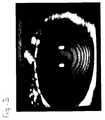
- the distance settingtakes place with the aid of an image on a pilot monitor, on which after analog filtering concentric rings appear on the cornea (Fig. 3) which cornea is imaged totally in the depth of focus of the cornea image.
- a yellow-band stop filter 11is fitted in front of the camera, which filter blocks the blue excitation light and transmits only the yellow emitted light.
- the unfiltered moiré image at the location of each CCD cameracontains pixel information on the spatial coordinates x, y and z.
- the shape of the corneaWith the aid of digital image processing it is possible to make the shape of the cornea visible in detail, for example as an axial section or as a three-dimensional structure.
- the ring patternsuch as that obtained after electronic analog filtering is not used as the starting point, but instead the unfiltered TV picture is analysed TV line by line.
- One method for analysing signalsis to use Fourier analysis.
- a condition for this analysisis that the signal is not overmodulated, as is unavoidable in the case of a moiré contrast.
- the TV pictures registeredcan be regarded as being phase-modulated, the height of the object to be measured being modulated in the phase of the projected grating.
- Figure 2shows in a one-dimensional manner how the grating is modulated and projected, in which:
- a data processing systemwill carry out these operations in discrete form.
- discrete Fourier transformthere is a very suitable method which reduces the number of calculations required. This is the so-called Fast Fourier Transform (FFT).
- FFTFast Fourier Transform
- the two-dimensional Fourier transformcomprises two one-dimensional transforms which can be carried out independently of each other, the same method as that mentioned in formula (3), (4), (5) and (6) applies.
- elliptical or polynomial curve fittingFor determining radii of curvature of a demodulated image it is possible to use, inter alia, elliptical or polynomial curve fitting.
- a method for thisis, for example, Gaussian elimination. Eccentricity, astigmatism and the like can be determined or calculated from these fittings.
- the determination of fittingscan also be carried out in a one-dimensional or a two-dimensional manner.
- the two-dimensional methodis more accurate, because in principle all measured image points are brought into relation with each other, which corresponds to reality. Measuring errors are also averaged out more effectively or are even eliminated in this way.
- digital filter techniqueswill be required.
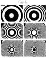
- FIGs 5 and 6in which a digitally obtained phase reconstruction of a (pilot) monitor line (projection on a spherical surface) and a two-dimensional reconstruction of a half TV raster of a spherical surface are respectively shown.
- the contourscan now be adjusted with intervals as desired. Details - such as a defect in the model top left - can thus be visualised.
- the lateral horizontal resolutionis determined by the band width of the TV system or by the resolution of the frame grabber, and no longer by the fringes of the moiré pattern, which as a beat pattern by definition have a much lower lateral resolution.
- the vertical resolutionis determined by the number of TV lines.
- the systemcan also be made suitable for determining the three-dimensional shape of other objects such as contact lenses, dentures, models and industrial objects.
- the systemcan be used such that by means of digital processing of the height contours already calculated the requested information for, for example, an optician, contact lens specialist, ophthalmologist or technician becomes available.
- the system according to the inventioncan be used for determining a curved surface, in which an accurate height line or contour pattern with a high lateral resolution is the basis for obtaining the required data, as needed, for example, for fitting contact lenses or for surgery in the ocular media.
- a height line mapcan be created on the cornea, comprising the whole cornea, and the detection device will also be designed in such a way that the whole height line map is available in real time in digital form for further data processing, with the result that an accurate determination of the central and peripheral curvature of the cornea becomes possible.
- the above systemincludes a projection device provided with two projectors disposed at an angle relative to each other, each positioned at right angles to the plane through the projection axes and a rectangular diaphragm, of which the long sides are parallel to the lines of the grating.
- a radiation load which is acceptable for the eye to be examinedwill be produced by making use of a relatively large diaphragm aperture from the detector side, even when using the required blue-green excitation light.
- the angle at which projection takes placedepends on the slope or curvature of the surface to be examined. Through the nature of the data processing, considerably larger projection angles are possible than in the case of direct formation of moiré images, while the sensitivity gain compared with respect to the direct moiré system also makes very small angles effective.
- a real-time moiré imageis created by means of an analog electronic filter, for a setting and viewfinder image.
- the light source used for the viewfinder imageis a lamp with slit shaped filament or slit shaped gas discharge, which is projected in vertical orientation on the vertical slit-shaped diaphragm of the projector.
- relatively coarse gratingsare projected, which gratings can still be projected with sufficient depth of field when the diaphragm aperture is large.
- the detection devicecan be embodied such that the definition of the height line map takes only a short time, with the result that possible movements of the eye during the exposure do not adversely affect the quality of the registration.
- Providing the object with a fluorescent layerprevents specular reflections in the case of this method.
- Useis made of a continuous light source which radiates light with a wavelength which causes emission in a fluorescent substance applied to the object.
- a substance which is suitable for thisis Na-fluorescein, of which the optimum excitation wavelength, depending on the solvent, is 460 to 510 nm (blue-green) and the emission wavelength is 520 - 560 nm (yellow).
- the projection deviceis fitted with a filter which transmits only light of the excitation wavelength, and in the detection system there is a filter which transmits only light of the emission wavelength. The interfering influences as the result of reflections of the excitation light are removed through this latter filter.
- the viewing axis and optical axis of the keratometercan be aligned as follows.
- the person to be examinedis asked to fix the eye on a light source, the optical axis of which coincides with the optical axis of the instrument.
- the operator of the keratometerensures then that this light source reflected by the eye goes into the centre of the image.
Landscapes
- Health & Medical Sciences (AREA)
- Life Sciences & Earth Sciences (AREA)
- Engineering & Computer Science (AREA)
- Physics & Mathematics (AREA)
- Surgery (AREA)
- Animal Behavior & Ethology (AREA)
- Biomedical Technology (AREA)
- Heart & Thoracic Surgery (AREA)
- Medical Informatics (AREA)
- Molecular Biology (AREA)
- Biophysics (AREA)
- Ophthalmology & Optometry (AREA)
- General Health & Medical Sciences (AREA)
- Public Health (AREA)
- Veterinary Medicine (AREA)
- Computer Vision & Pattern Recognition (AREA)
- General Physics & Mathematics (AREA)
- Length Measuring Devices By Optical Means (AREA)
- Eye Examination Apparatus (AREA)
- Measurement Of The Respiration, Hearing Ability, Form, And Blood Characteristics Of Living Organisms (AREA)
Description
- The invention relates to a system for determining the topography of a curved surface, comprising a projection device for projecting patterns of lines on the surface, which projection device includes two independent light projectors disposed at an angle relative to each other, each projector having a projection optical axis and including a grating having parallel straight lines, wherein each grating is positioned at a right angle to the projection optical axis of its projector, and a rectangular diaphragm having the long sides parallel to the lines of the grating, and a detection device for registering an image formed on the curved surface. Such systems are used, inter alia, in the case of the so-called keratometer for determining the external shape of the human eye, in particular the curvature of the external surface of the cornea, for example for measuring for contact lenses and accurately determining the topography of the cornea before and after surgery.
- These systems can also be used in manufacturing and checking curved objects.
- With the known commercially available photokeratometer the radius of curvature of the cornea is measured locally by comparing mirrored measurement figures on the interface between air and lacrimal fluid with test figures.
- Places of equal slope can be mapped in this way. In the interpretation of such registrations, without previous knowledge of the object, errors cannot be ruled out. Only a limited area of the cornea is measured.
- Unequivocal registrations of the topography of the surface of the cornea can be obtained with the keratometer of the type which is described in an article by Tetsuo Kawara, "Corneal topography using moiré contour fringes", in Applied Optics, Vol. 18, pp. 3675-3678 (Nov. 1979). Such a keratometer makes use of moiré contour lines, which are lines of equal height. For this purpose, the reflecting surface of the cornea is transformed into a perfectly diffusely radiating surface, through the application of a fluorescein film, as is necessary for said moiré technique. The fluorescent light of the fluorescein film is used to form the image, while the excitation light (which through specular reflection could distort the image) of the projection device, consisting of a single projector, is filtered out. In order to achieve the accuracy for a spherical surface which he claimed, Tetsuo Kawara used a grating with approximately 12 line pairs per millimetre (lp/mm) which, because of a narrow slit-shaped diaphragm in the projection device having optical compensation for the slanting projection angle relative to the viewing axis of the keratometer and a small enough diaphragm of the camera with the required depth of field, forms an image on the reference grating of the camera.
- Due to the slanting projection angle, the camera "sees" a superimposed pattern of a projected grating slightly deformed by the convex cornea and the reference grating. The spatial beat between the gratings, which becomes visible as an interference phenomenon, is known as moiré. This interference image represents lines of equal height. Since in this moiré arrangement a multiplication contrast is obtained, the height lines can be read directly from the photographs. Translation of these height lines into three meridional profiles produces information on the local radius of curvature of the cornea.
- A serious general limitation of the moiré projection system described is that, on the one hand, sufficient depth of field is required, for which a small diaphragm is needed, while, on the other hand, the height contour interval must be as small as possible, which only a grating with a large number of lp/mm can provide. The system described by Tetsuo Kawara is therefore diffraction limited. A higher resolution can be obtained only at the expense of the depth of field, or by increasing the projection angle of the grating relative to the optical axis of the camera. With a small depth of field the whole cornea is not mapped in one exposure, and a larger projection angle than approximately 18° produces an image which can no longer be interpreted visually, on account of the occurrence of optical artifacts. In the case of the instrument described the height lines are displayed at the position of the reference grating instead of being located on the surface to be registered, which means that the flexibility of the instrument with regard to variation of image scale and image angle is low. The sign of the slope is not known (from previous knowledge is derived as "convex"). The product of Tetsuo Kawara's keratometer is a photograph. The translation of the height lines thus recorded into local radius of curvature, eccentricity etc. has to be carried out from there.
- The dependence on very fine gratings in order to keep the moiré contour interval (= measuring point) limited, could be removed in principle if, instead of the intensity distribution of the moiré image, the local phase of the projected grating were used as the measuring point.
- Moiré height lines of a surface of an object are formed by the relative phases between the projected grating and the reference grating. The height lines will shift due to shifting of one of the gratings, with the result that a continuous phase measurement at one measuring point is possible. The intensity variation is then a measure of the phase variation. The measuring sensitivity and the accuracy then increase greatly. Since the movement device of the moving grating is known, the sign of the slope can be determined. In the case of the keratometer, on account of unavoidable eye movements, it is hardly possible to carry out such a dynamic measurement.
- However, in the examination of surfaces of other objects, such as dentures, the use of a device is known from an article by F.H.M. Jongsma et al., "Real-time contouring of tooth imprints", in SPIE, Vol. 492, pp. 500-506, ECOOSA 1984, in which two interference patterns are projected at an angle relative to each other by means of an interferometer. Planes which are at right angles to the bisectrix of the angle and are alternately diffusely illuminated or contain more or less highly contrasting line patterns are thereby produced in the space in which the two light beams intersect. The distance between these parallel planes is equal and depends on the angle between the light beams and the distance between the lines in the projected grating pattern. If an object is now placed in this space, it alternately intersects the diffusely illuminated planes and the planes with the images of the grating pattern. As a result of this, intersection lines become visible on the object, which lines have a constant height difference from each other, although due to the summation effect the contrast of the two intensities is very low. In order to make said height lines visible, a spatial (optical) or temporal (electronic) filtering such as that described in above article by Jongsma et al. must therefore still be used.
- A disadvantage of moiré images is that it is not possible to determine the sign of the slope other than from previous knowledge of the object. One method of overcoming this problem is described in French patent application No. 2,292,213 of 21 November 1974. This patent application describes a method in which two moiré projections are compared with each other. These moiré registrations are produced in such a way that the reference plane of the second moiré registration is displaced over a distance which is smaller than half the moiré contour distance. Double contours with alternating small and larger intervals are thus produced. The contours are labelled with a colour, for example by making use of a yellow and a blue grating. The result is then a colour registration with the relatively small contour intervals yellow - blue or blue - yellow. The information of the sign of the slope is contained in the combination of distance and colour.
- Another form of colour labelling is described in German patent application No.
P 40 075 028 of 9 March 1990. This patent application describes how two gratings of different colours are projected simultaneously on the object from different angles. The two gratings can be processed in the detection system separately by means of a colour separation mirror. The angle and the orientation of the slope relative to the sensor can then be calculated from the local spatial grating frequency on the object. What is essential in this system is the mechanical linking of the two gratings lying in one plane, so that their phase relation is fixed. As a result of this, by displacement of the gratings the noise can be averaged, while the height contours do not change position. - If unambiguous external shape information on the moist and reflecting surface of the cornea is desired, use can be made of the fluorescence technique described in the article by T. Kawara, in order to convert this reflecting surface into a Lambertian radiator. In these conditions, when there is a well-defined illumination, the local emission can then be calculated. In order to obtain a moiré contrast, use can be made of the projection technique known from an article by J. Wasowski, "Moiré topographic maps", in Opt. Communications, Vol. 2, pp. 321-323, 1970, by means of a projector of the type described by Kawara. If lasers which are suitable for this are available, it is also possible to choose the interferometer described by Wasowski as the grating producer, or another interference system can be used.
- The invention aims at obviating the earlier mentioned problems in the prior art. This is realized, according to the invention, in that the projection device comprises, in each projector, a flash light source synchronised in sequence with the detection device, and in that the detection device comprises a frame grabber for separately registering a projected grating of each projector in said sequence, respectively, for digital image analysis to obtain the topography of the curved surface. Hereby the system is implemented such that an additive moiré pattern is produced. In a further embodiment a pilot monitor in conjunction with an electronic filter is provided for real-time visualizing this moiré patter, the detection device being implemented for registering the image without moiré interference, suitable for discrete Fourier analysis.
- The invention is explained in greater detail with reference to an example of an embodiment shown diagrammatically in the drawings, in which
- Fig. 1 shows diagrammatically a system according to the invention;
- Fig. 2 shows the projection of the intensity function on the x-axis through object c(x);
- Fig. 3 shows an electronic real-time filtered viewfinder image;
- Fig. 4a, 4b and 4c respectively show a complete TV picture and the separate components from which it is composed, the first half raster (fig 4b) and the second half raster (fig 4c);
- Fig. 5 shows a digitally obtained phase reconstruction of a TV line; and
- Fig. 6 shows a 2-D reconstruction of a half TV raster of a spherical surface.
- On account of the gain in sensitivity and accuracy which can be achieved with phase detection, a calculation program has been developed, in which the local phase of a projected grating on the surface to be measured is calculated relative to a reference plane at right angles to the optical axis of the sensor. Since the carrier wave itself, and not the modulation of the carrier wave, is now the basis for extracting the information, it is possible to work with relatively coarse gratings which permit correspondingly larger diaphragms. In this way it becomes possible, without causing too great a radiation load for the eye, to use a high-resolution TV camera, such as a CCD camera, which permit real-time digitising of the images through the use of a frame grabber.
- The cornea to be measured is mobile and cannot be fixed, with the result that the collection time has to be very short (shorter than the integration time of a TV camera). Moreover, a part of the image can be lost through local overexposure, due to reflection on the cornea.
- These problems can be solved by making use of a TV camera, like a CCD camera, and two flash tubes synchronised with the camera such as is indicated in Fig. 1. The first tube is synchronised in the end of the first half raster period, and the second at the beginning of the next half raster. The total integration time is now limited to the flash times and the flash interval. Since the two flash exposures produce an independent picture independently of each other (but linked in time), one picture can supplement the information which has been lost in the other picture, for instance caused by local disturbances like undesired reflections, too strong defocussing, etc. This situation is achieved in the case of the double flash technique described, in which it is possible, for example, first to analyse the odd TV lines and then to analyse the even lines.
- The system for use in the invention, as indicated in Figure 1, comprises two projectors 3 set up at an angle with the optical axis 1 of a camera 2. Both projectors contain a slide or grating 4 containing a line pattern of about five line pairs per mm, which lines run at right angles to the plane through the projection axes. As described above, by projection of two line patterns at an angle, diffusely illuminated planes and planes with more or less highly contrasting raster images are produced alternately in the
space 12 in which the two light beams cross, which images produce a height line or contour chart on intersection by an object. - The eye to be examined is treated with Na-fluorescein in Hypromellose-Bournonville®, a substance which is also used as a replacement for natural tear moisture in the case of "dry eyes". Hypromellose serves as a solvent for Na-fluorescein. Blinking a few times causes the Na-fluorescein to be absorbed in the tear film, following which the registration can be taken.
- For accurate measurements of the cornea contours, in which the liquid film must have a uniform thickness, use can be made of Healon®, which has a low molecular weight, and in which Na-fluorescein is dissolved, as known, for example, in the case of cornea plastic with the aid of excimer lasers.
- Projection lamps 5 are used as the light source in the projectors. In order to "freeze" rapid eye movements, use can be made of flash lamps 6 which are synchronised with the TV camera, and which then temporarily replace the continuous lamps in the projectors. Filters are fitted between the lamps and the slides, which filters reflect (7) the heat of the light source and reflect (8) all colours except blue-green, so that the radiation load on the eye is restricted to that of the blue-green excitation light. For projecting the grating, the projection device is provided with a projection objective 10. Placed in the focal plane of this projection objective at the side where the object lies is a rectangular diaphragm 9, of which the long sides run parallel to the lines of the grating. The aperture of the diaphragm along the narrow side is small enough to project five line pairs per mm with sufficient depth of field. The relatively large aperture of the diaphragm along the long side contributes to the desired light intensity of the height line map.
- The distance setting takes place with the aid of an image on a pilot monitor, on which after analog filtering concentric rings appear on the cornea (Fig. 3) which cornea is imaged totally in the depth of focus of the cornea image.
- A yellow-
band stop filter 11 is fitted in front of the camera, which filter blocks the blue excitation light and transmits only the yellow emitted light. - The unfiltered moiré image at the location of each CCD camera contains pixel information on the spatial coordinates x, y and z. With the aid of digital image processing it is possible to make the shape of the cornea visible in detail, for example as an axial section or as a three-dimensional structure. In order to obtain both a high axial and a high lateral resolution, the ring pattern such as that obtained after electronic analog filtering is not used as the starting point, but instead the unfiltered TV picture is analysed TV line by line.
- As soon as the instrument is set, a frame grabber sees to the digitisation and the transmission of the signal to the monitor coupled to a computer. There the signal is analysed line by line (Fig. 4). This takes place both for the left-hand projection and for the right-hand projection in the calculation, possibly simultaneously. In this way any missing information in one image can be supplemented through the other image. This also applies to defocussing effects, which in the case of the two projections are left-right opposed.
- One method for analysing signals is to use Fourier analysis. A condition for this analysis is that the signal is not overmodulated, as is unavoidable in the case of a moiré contrast. The TV pictures registered can be regarded as being phase-modulated, the height of the object to be measured being modulated in the phase of the projected grating.
- Figure 2 shows in a one-dimensional manner how the grating is modulated and projected, in which:
- a(x)
- = perpendicular line of p(x) through the origin
- {Z(x)}
- = collection of perpendicular lines of p(x) with an intersection point with c(x): β
- ϕ
- = projection angle
- p(x)
- = intensity function axis with O as origin
- α
- = distance between α(x) and any line of Z(x) representing the original phase angle produced by the raster
- β
- = abscis value of the intersection point with c(x) representing the phase angle which comes about after projection
- The diaphragm setting, passes the first and zeroth order, with the result that the intensity can be characterised by:

- ωo
- : raster function
- A
- : amplitude
- d
- : D.C. shift
- The projected modulated wave form then acquires a shape of the type:

- c(β)
- = height of the object written as function,
- ϕ
- = projection angle.
- T
- : constant factor
- F{ }
- : forward Fourier transform
- F-1{ }
- : backward Fourier transform
- D{ }
- : demodulation transform
- arg( )
- : argument/phase of a complex number/series
- k
- : constant, element of

- A data processing system will carry out these operations in discrete form. For the discrete Fourier transform there is a very suitable method which reduces the number of calculations required. This is the so-called Fast Fourier Transform (FFT). In analogy to the one-dimensional analysis technique described, there is the possibility of carrying out a two-dimensional analysis. Since the two-dimensional Fourier transform comprises two one-dimensional transforms which can be carried out independently of each other, the same method as that mentioned in formula (3), (4), (5) and (6) applies.
- For determining radii of curvature of a demodulated image it is possible to use, inter alia, elliptical or polynomial curve fitting. A method for this is, for example, Gaussian elimination. Eccentricity, astigmatism and the like can be determined or calculated from these fittings. The determination of fittings can also be carried out in a one-dimensional or a two-dimensional manner. For both transform technique and fitting technique the two-dimensional method is more accurate, because in principle all measured image points are brought into relation with each other, which corresponds to reality. Measuring errors are also averaged out more effectively or are even eliminated in this way. In order to achieve further improvements, digital filter techniques will be required.
- For an example of above processing reference is made to Figures 5 and 6, in which a digitally obtained phase reconstruction of a (pilot) monitor line (projection on a spherical surface) and a two-dimensional reconstruction of a half TV raster of a spherical surface are respectively shown. In figure 6, the contours can now be adjusted with intervals as desired. Details - such as a defect in the model top left - can thus be visualised.
- In the above explained technique the lateral horizontal resolution is determined by the band width of the TV system or by the resolution of the frame grabber, and no longer by the fringes of the moiré pattern, which as a beat pattern by definition have a much lower lateral resolution. The vertical resolution is determined by the number of TV lines. Apart from being used as a keratometer, on account of the absence of the need for having previous knowledge of the object to determine the sign of the slope, the system can also be made suitable for determining the three-dimensional shape of other objects such as contact lenses, dentures, models and industrial objects. Advantageously, the system can be used such that by means of digital processing of the height contours already calculated the requested information for, for example, an optician, contact lens specialist, ophthalmologist or technician becomes available.
- The system according to the invention can be used for determining a curved surface, in which an accurate height line or contour pattern with a high lateral resolution is the basis for obtaining the required data, as needed, for example, for fitting contact lenses or for surgery in the ocular media. When the system is used as a keratometer, a height line map can be created on the cornea, comprising the whole cornea, and the detection device will also be designed in such a way that the whole height line map is available in real time in digital form for further data processing, with the result that an accurate determination of the central and peripheral curvature of the cornea becomes possible.
- This is obtained through the fact that the above system includes a projection device provided with two projectors disposed at an angle relative to each other, each positioned at right angles to the plane through the projection axes and a rectangular diaphragm, of which the long sides are parallel to the lines of the grating.
- Through the use of these projectors, diffusely illuminated planes and planes with more or less highly contrasting grating images can be obtained, which when intersected by an object produce a highly contrasting moiré contour or height line map after analog or digital processing of the signal.
- A radiation load which is acceptable for the eye to be examined will be produced by making use of a relatively large diaphragm aperture from the detector side, even when using the required blue-green excitation light.
- The angle at which projection takes place depends on the slope or curvature of the surface to be examined. Through the nature of the data processing, considerably larger projection angles are possible than in the case of direct formation of moiré images, while the sensitivity gain compared with respect to the direct moiré system also makes very small angles effective. In the case of the keratometer a real-time moiré image is created by means of an analog electronic filter, for a setting and viewfinder image.
- In addition, in particular in the case of keratometers, the light source used for the viewfinder image is a lamp with slit shaped filament or slit shaped gas discharge, which is projected in vertical orientation on the vertical slit-shaped diaphragm of the projector. In order to minimise the thermal load of the projection device and in order to keep the light load of the eye low, relatively coarse gratings are projected, which gratings can still be projected with sufficient depth of field when the diaphragm aperture is large. The detection device can be embodied such that the definition of the height line map takes only a short time, with the result that possible movements of the eye during the exposure do not adversely affect the quality of the registration.
- Through specular reflections of the surface of the object, differences can occur in the intensities of the two grating images, with the result that the derivation of the phase height of the gratings from the local intensity is jeopardised, and so also is the formation of the height line map.
- Providing the object with a fluorescent layer prevents specular reflections in the case of this method. Use is made of a continuous light source which radiates light with a wavelength which causes emission in a fluorescent substance applied to the object. A substance which is suitable for this is Na-fluorescein, of which the optimum excitation wavelength, depending on the solvent, is 460 to 510 nm (blue-green) and the emission wavelength is 520 - 560 nm (yellow). The projection device is fitted with a filter which transmits only light of the excitation wavelength, and in the detection system there is a filter which transmits only light of the emission wavelength. The interfering influences as the result of reflections of the excitation light are removed through this latter filter. In the case of the keratometer embodiment, the viewing axis and optical axis of the keratometer can be aligned as follows. The person to be examined is asked to fix the eye on a light source, the optical axis of which coincides with the optical axis of the instrument. The operator of the keratometer ensures then that this light source reflected by the eye goes into the centre of the image.


The phase, thus the height of the object, can be reconstructed from the modulated wave form i(β) by means of the Fourier transform. In principle, the following steps are necessary to reconstruct the height:


Claims (10)
- A system for determining the topography of a curved surface, comprising a projection device for projecting patterns of lines on the surface, which projection device includes two independent light projectors (3) disposed at an angle relative to each other, each projector having a projection optical axis and including a grating (4) having parallel straight lines, wherein each grating is positioned at a right angle to the projection optical axis of its projector, and a rectangular diaphragm (9) having the long sides parallel to the lines of the grating, and a detection device for registering an image formed on the curved surface, characterised in that the projection device comprises, in each projector, a flash light source (6) synchronised in sequence with the detection device, and in that the detection device comprises a frame grabber for separately registering a projected grating of each projector in said sequence, respectively, for digital image analysis to obtain the topography of the curved surface.
- A system according to claim 1, wherein the detection device comprises a TV-camera (2) and a synchronizer means for triggering the flash light source (6) of the first projector at the end of a first half TV-raster period and for triggering the flash light source of the second projector at the beginning of a second half TV-raster period, respectively, the flash light sources illuminating a complete TV-raster wherein the half rasters are adapted to complement each other afterwards.
- A system according to claim 2, wherein the detection device further comprises a data processor for analyzing the image to obtain a height function, according to Fourier transform, demodulation, and inverse Fourier transform, on one or more half TV-rasters simultaneously in a one or two dimensional manner for reconstructing the topography.
- A system according to claim 1, wherein each light projector further comprises a continuous light source (5), wherein the continuous and flash light sources are slit shaped such that the continuous light and flash light is projected from the projectors in a vertical orientation through the rectangular diaphragm.
- A system according to claim 4, wherein the detection device comprises an analogue contrast filter and a pilot monitor, whereby the analog filter emphasizes additive height contours in real time on a topography image which is displayed on the pilot monitor.
- A system according to claim 1, wherein the projectors of the projection device are each disposed at an angle ranging from 10° to 45°.
- A system according to claim 1, wherein each projector comprises a grating projecting objective (10), the rectangular diaphragm (9) being placed in a focal plane of the objective.
- A system according to claim 3, wherein the projectors are angled to cause the projected gratings to intersect on the curved surface, wherein the frame grabber is capable of distinguishing the intersecting gratings and separately registering the gratings for individual digital analysis via the data processor.
- A system according to claim 1 to 8, for use as a contact lens fitting device.
- A system according to claim 1 to 8, for use as a keratometer.
Applications Claiming Priority (2)
| Application Number | Priority Date | Filing Date | Title |
|---|---|---|---|
| NL9200071ANL9200071A (en) | 1992-01-15 | 1992-01-15 | DEVICE FOR DETERMINING THE TOPOGRAPHY OF A CURVED SURFACE. |
| NL9200071 | 1992-01-15 |
Publications (2)
| Publication Number | Publication Date |
|---|---|
| EP0551955A1 EP0551955A1 (en) | 1993-07-21 |
| EP0551955B1true EP0551955B1 (en) | 1997-08-13 |
Family
ID=19860300
Family Applications (1)
| Application Number | Title | Priority Date | Filing Date |
|---|---|---|---|
| EP93200102AExpired - LifetimeEP0551955B1 (en) | 1992-01-15 | 1993-01-15 | System for determining the topography of a curved surface |
Country Status (7)
| Country | Link |
|---|---|
| US (1) | US5406342A (en) |
| EP (1) | EP0551955B1 (en) |
| JP (1) | JP2599876B2 (en) |
| DE (1) | DE69312975T2 (en) |
| DK (1) | DK0551955T3 (en) |
| ES (1) | ES2108203T3 (en) |
| NL (1) | NL9200071A (en) |
Cited By (1)
| Publication number | Priority date | Publication date | Assignee | Title |
|---|---|---|---|---|
| WO2017125528A1 (en) | 2016-01-20 | 2017-07-27 | Eaglet Eye B.V. | Improved eye surface topographer |
Families Citing this family (49)
| Publication number | Priority date | Publication date | Assignee | Title |
|---|---|---|---|---|
| US6454761B1 (en)* | 1995-01-30 | 2002-09-24 | Philip D. Freedman | Laser surgery device and method |
| US5867250A (en)* | 1996-05-03 | 1999-02-02 | Baron; William S. | Apparatus and method for optically mapping front and back surface topographies of an object |
| US5735283A (en)* | 1996-10-09 | 1998-04-07 | Snook; Richard Kieth | Surgical keratometer system for measuring surface topography of a cornea during surgery |
| US5864383A (en)* | 1997-04-24 | 1999-01-26 | Orbtek, Inc. | Single-curvature placido plate |
| US6079831A (en)* | 1997-04-24 | 2000-06-27 | Orbtek, Inc. | Device and method for mapping the topography of an eye using elevation measurements in combination with slope measurements |
| DE19815201A1 (en)* | 1998-04-04 | 1999-10-07 | Link Johann & Ernst Gmbh & Co | Measuring arrangement for detecting dimensions of test specimens, preferably of hollow bodies, in particular of bores in workpieces, and methods for measuring such dimensions |
| US6024449A (en)* | 1998-07-13 | 2000-02-15 | Smith; Robert F. | High speed topography measurement of semi-diffuse objects |
| JP2000292135A (en)* | 1999-04-07 | 2000-10-20 | Minolta Co Ltd | Three-dimensional information input camera |
| CA2391325C (en)* | 1999-07-28 | 2009-12-15 | Visx, Inc. | Hydration and topography tissue measurements for laser sculpting |
| US6639685B1 (en) | 2000-02-25 | 2003-10-28 | General Motors Corporation | Image processing method using phase-shifted fringe patterns and curve fitting |
| US7190377B2 (en)* | 2000-03-29 | 2007-03-13 | Sourceprose Corporation | System and method for georeferencing digital raster maps with resistance to potential errors |
| US7038681B2 (en)* | 2000-03-29 | 2006-05-02 | Sourceprose Corporation | System and method for georeferencing maps |
| US7148898B1 (en)* | 2000-03-29 | 2006-12-12 | Sourceprose Corporation | System and method for synchronizing raster and vector map images |
| SE0003904L (en)* | 2000-05-05 | 2001-11-06 | Roger Tuomas | Ways of measuring surface roughness |
| FR2817042B1 (en)* | 2000-11-22 | 2003-06-20 | Saint Gobain | METHOD AND DEVICE FOR ANALYZING THE SURFACE OF A SUBSTRATE |
| DE10061326A1 (en) | 2000-12-08 | 2002-06-27 | Bioshape Ag | Method and device for determining the topology of biological tissue |
| JP3519698B2 (en)* | 2001-04-20 | 2004-04-19 | 照明 與語 | 3D shape measurement method |
| DE10132309B4 (en)* | 2001-07-06 | 2006-09-21 | Geometrie Concern Verwaltungs- Und Beteiligungsgesellschaft Mbh | Visual inspection procedure and control system |
| US6575573B2 (en) | 2001-10-17 | 2003-06-10 | Carl Zeiss Ophthalmic Systems, Inc. | Method and apparatus for measuring a corneal profile of an eye |
| US7164817B2 (en) | 2002-05-24 | 2007-01-16 | Hoya Corporation | Optical switch and optical add/drop multiplexer using the same |
| JP3939325B2 (en) | 2002-05-24 | 2007-07-04 | Hoya株式会社 | Optical switch and optical add / drop device using the same |
| EP1516156B1 (en)* | 2002-05-30 | 2019-10-23 | AMO Manufacturing USA, LLC | Tracking torsional eye orientation and position |
| US7083609B2 (en)* | 2002-06-13 | 2006-08-01 | Visx, Incorporated | Corneal topography-based target warping |
| US7133137B2 (en) | 2002-06-27 | 2006-11-07 | Visx, Incorporated | Integrated scanning and ocular tomography system and method |
| US7458683B2 (en) | 2003-06-16 | 2008-12-02 | Amo Manufacturing Usa, Llc | Methods and devices for registering optical measurement datasets of an optical system |
| US7481536B2 (en)* | 2004-02-19 | 2009-01-27 | Amo Manufacturing Usa, Llc | Methods and systems for differentiating left and right eye images |
| US7369253B2 (en)* | 2004-10-13 | 2008-05-06 | Akrometrix, Llc | Systems and methods for measuring sample surface flatness of continuously moving samples |
| US7866820B2 (en)* | 2006-02-14 | 2011-01-11 | Vision Optimization, Llc | Corneo-scleral topography system |
| DE102006028238B3 (en)* | 2006-06-20 | 2007-07-19 | Benecke-Kaliko Ag | Three dimensionally structured original surface e.g. grained surface, reflection characteristics analysis and specification method, involves storing reflection value in data record that is provided to processing or verification system |
| DE102007017611A1 (en)* | 2007-04-12 | 2008-10-16 | SCHRÜNDER, Stephan | Method and system for eye measurement |
| EP2040061A1 (en)* | 2007-09-24 | 2009-03-25 | Koninklijke Philips Electronics N.V. | An apparatus and method for observing the surface of a sample |
| WO2009094510A1 (en)* | 2008-01-25 | 2009-07-30 | Cyberoptics Corporation | Multi-source sensor for three-dimensional imaging using phased structured light |
| US8059280B2 (en)* | 2008-01-31 | 2011-11-15 | Cyberoptics Corporation | Method for three-dimensional imaging using multi-phase structured light |
| CA2731811C (en)* | 2008-04-04 | 2016-12-13 | Amo Wavefront Sciences, Llc | Registering multiple ophthalmic datasets |
| US9504376B2 (en) | 2009-12-22 | 2016-11-29 | Amo Wavefront Sciences, Llc | Optical diagnosis using measurement sequence |
| JP5743433B2 (en)* | 2010-06-03 | 2015-07-01 | 株式会社マクシス・シントー | 3D shape measuring device |
| GB201010244D0 (en)* | 2010-06-18 | 2010-07-21 | Hyde John | Line and image capture for 3D applications independent of high ambient lighting conditions |
| DE102010060448B4 (en)* | 2010-11-09 | 2021-07-01 | Eberhard Lange | Projection device for projecting an object to be projected |
| EP2785294B1 (en) | 2011-11-30 | 2016-11-23 | AMO Development, LLC | System and method for ophthalmic surface measurements based on sequential estimates |
| WO2015054672A1 (en) | 2013-10-10 | 2015-04-16 | The Regents Of The University Of California | Ocular cellscope apparatus |
| WO2015070006A1 (en)* | 2013-11-08 | 2015-05-14 | Precision Ocular Metrology, L.L.C. | Mapping the ocular surface |
| CN105890876B (en)* | 2014-12-10 | 2018-07-06 | 青岛理工大学 | Sinusoidal light intensity target optical signal generation method and system |
| WO2016123448A2 (en)* | 2015-01-30 | 2016-08-04 | Catanzariti Scott Paul | Systems and method for mapping the ocular surface usually obstructed by the eyelids |
| DE102015001365A1 (en)* | 2015-02-03 | 2016-08-04 | EnShape GmbH | METHOD FOR 3D-MEASUREMENT OF LIQUIDS AND GELS |
| WO2017180965A1 (en) | 2016-04-15 | 2017-10-19 | The Regents Of The University Of California | Retinal cellscope apparatus |
| WO2020102658A2 (en)* | 2018-11-16 | 2020-05-22 | Carestream Dental Llc | Laser projection system |
| WO2021003444A2 (en)* | 2019-07-02 | 2021-01-07 | Nikon Corporation | Metrology for additive manufacturing |
| CN110897608B (en)* | 2019-12-15 | 2022-05-03 | 深圳市具安科技有限公司 | Zebra fish eye movement analysis method and device and computer equipment |
| US20230091424A1 (en)* | 2021-09-17 | 2023-03-23 | San Diego State University (Sdsu) Foundation, Dba San Diego State University | Method and system for moiré profilimetry using simultaneous dual fringe projection |
Family Cites Families (10)
| Publication number | Priority date | Publication date | Assignee | Title |
|---|---|---|---|---|
| FR2254781A1 (en)* | 1973-12-18 | 1975-07-11 | Schaeffer Bernard | Rastered photogrammetry technique - involves projecting image of rastered object through second raster |
| FR2292213A1 (en)* | 1974-11-21 | 1976-06-18 | Cem Comp Electro Mec | Map contour-line reading instrument - determines relative position of lines using moire fringe effect produced by structured beams of light |
| FR2337329A1 (en)* | 1975-12-29 | 1977-07-29 | Cem Comp Electro Mec | Optical comparator for spatial coordinates - projects two grid patterns on surface of tested object from optical systems fixed w.r.t. reference point |
| JPS61219804A (en)* | 1985-03-27 | 1986-09-30 | Hitachi Ltd | Method for measuring height of wire material |
| JPS6345113A (en)* | 1986-08-13 | 1988-02-26 | Catalysts & Chem Ind Co Ltd | Silica sol having low turbidity and low viscosity |
| US4722600A (en)* | 1986-10-14 | 1988-02-02 | Chiang Fu Pen | Apparatus and method for measuring strain |
| JPH02119837A (en)* | 1988-10-28 | 1990-05-07 | Kowa Co | Ophthalmological measurement method and device |
| JPH02271208A (en)* | 1989-04-13 | 1990-11-06 | Nippondenso Co Ltd | Measuring apparatus of three-dimensional shape |
| DE4007500A1 (en)* | 1990-03-09 | 1991-09-12 | Zeiss Carl Fa | METHOD AND DEVICE FOR CONTACTLESS MEASUREMENT OF OBJECT SURFACES |
| DE4007502A1 (en)* | 1990-03-09 | 1991-09-12 | Zeiss Carl Fa | METHOD AND DEVICE FOR CONTACTLESS MEASUREMENT OF OBJECT SURFACES |
- 1992
- 1992-01-15NLNL9200071Apatent/NL9200071A/ennot_activeApplication Discontinuation
- 1993
- 1993-01-15ESES93200102Tpatent/ES2108203T3/ennot_activeExpired - Lifetime
- 1993-01-15USUS08/005,244patent/US5406342A/ennot_activeExpired - Fee Related
- 1993-01-15EPEP93200102Apatent/EP0551955B1/ennot_activeExpired - Lifetime
- 1993-01-15DEDE69312975Tpatent/DE69312975T2/ennot_activeExpired - Fee Related
- 1993-01-15DKDK93200102.7Tpatent/DK0551955T3/enactive
- 1993-01-18JPJP5006103Apatent/JP2599876B2/ennot_activeExpired - Fee Related
Cited By (2)
| Publication number | Priority date | Publication date | Assignee | Title |
|---|---|---|---|---|
| WO2017125528A1 (en) | 2016-01-20 | 2017-07-27 | Eaglet Eye B.V. | Improved eye surface topographer |
| US11154190B2 (en) | 2016-01-20 | 2021-10-26 | Eaglet Eye B.V. | Eye surface topographer |
Also Published As
| Publication number | Publication date |
|---|---|
| US5406342A (en) | 1995-04-11 |
| DE69312975D1 (en) | 1997-09-18 |
| NL9200071A (en) | 1993-08-02 |
| ES2108203T3 (en) | 1997-12-16 |
| DE69312975T2 (en) | 1998-03-05 |
| JPH0771934A (en) | 1995-03-17 |
| JP2599876B2 (en) | 1997-04-16 |
| EP0551955A1 (en) | 1993-07-21 |
| DK0551955T3 (en) | 1998-03-30 |
Similar Documents
| Publication | Publication Date | Title |
|---|---|---|
| EP0551955B1 (en) | System for determining the topography of a curved surface | |
| US5867250A (en) | Apparatus and method for optically mapping front and back surface topographies of an object | |
| US4692003A (en) | Real-time analysis keratometer | |
| US5159361A (en) | Method and apparatus for obtaining the topography of an object | |
| EP0314471B1 (en) | Three-dimensional shape measurement apparatus | |
| US4995716A (en) | Method and apparatus for obtaining the topography of an object | |
| US5835218A (en) | Moire interferometry system and method with extended imaging depth | |
| US5592246A (en) | Device and method for mapping objects | |
| EP0768511A1 (en) | Optical three-dimensional profilometry method based on processing speckle images in partially coherent light, and interferometer implementing such a method | |
| EP1391176A1 (en) | Method and arrangement for performing measurements of the topography of a corneal surface | |
| JPH0646999A (en) | Alignment detector | |
| US4867554A (en) | Surface examining apparatus | |
| CN110325101B (en) | Method and device for high-resolution topographic mapping of the cornea of an eye | |
| JPH09507293A (en) | Shape measuring system | |
| US6771362B2 (en) | Method and apparatus for testing and mapping phase objects | |
| Dirckx et al. | Optoelectronic moiré projector for real-time shape and deformation studies of the tympanic membrane | |
| US5075560A (en) | Moire distance measurements using a grating printed on or attached to a surface | |
| FR2720523A1 (en) | Optical device for viewing a three-dimensional virtual image superimposed on a real object, in particular for surgical applications. | |
| JP2912287B2 (en) | Fundus three-dimensional shape measurement device | |
| US3874796A (en) | Method of surface contouring | |
| Boone | Optical methods to measure shape and size | |
| Dirckx et al. | Video moiré topography for in-vitro studies of the eardrum | |
| ANGMAR-MÅNSSON et al. | OPTICAL METHODS TO MEASURE SHAPE AND SIZE. | |
| Marshall | Development and evaluation of depth estimation from plenoptic imaging for application in retinal imaging | |
| HU198246B (en) | Method and device for three phase detecting form, defformations or errors in form of surfaces |
Legal Events
| Date | Code | Title | Description |
|---|---|---|---|
| PUAI | Public reference made under article 153(3) epc to a published international application that has entered the european phase | Free format text:ORIGINAL CODE: 0009012 | |
| AK | Designated contracting states | Kind code of ref document:A1 Designated state(s):BE CH DE DK ES FR GB IT LI NL SE | |
| 17P | Request for examination filed | Effective date:19940117 | |
| 17Q | First examination report despatched | Effective date:19950330 | |
| GRAG | Despatch of communication of intention to grant | Free format text:ORIGINAL CODE: EPIDOS AGRA | |
| GRAH | Despatch of communication of intention to grant a patent | Free format text:ORIGINAL CODE: EPIDOS IGRA | |
| GRAH | Despatch of communication of intention to grant a patent | Free format text:ORIGINAL CODE: EPIDOS IGRA | |
| GRAA | (expected) grant | Free format text:ORIGINAL CODE: 0009210 | |
| AK | Designated contracting states | Kind code of ref document:B1 Designated state(s):BE CH DE DK ES FR GB IT LI NL SE | |
| REG | Reference to a national code | Ref country code:CH Ref legal event code:EP | |
| ITF | It: translation for a ep patent filed | ||
| REG | Reference to a national code | Ref country code:CH Ref legal event code:NV Representative=s name:R. A. EGLI & CO. PATENTANWAELTE | |
| REF | Corresponds to: | Ref document number:69312975 Country of ref document:DE Date of ref document:19970918 | |
| ET | Fr: translation filed | ||
| REG | Reference to a national code | Ref country code:ES Ref legal event code:FG2A Ref document number:2108203 Country of ref document:ES Kind code of ref document:T3 | |
| REG | Reference to a national code | Ref country code:DK Ref legal event code:T3 | |
| PLBE | No opposition filed within time limit | Free format text:ORIGINAL CODE: 0009261 | |
| STAA | Information on the status of an ep patent application or granted ep patent | Free format text:STATUS: NO OPPOSITION FILED WITHIN TIME LIMIT | |
| 26N | No opposition filed | ||
| PGFP | Annual fee paid to national office [announced via postgrant information from national office to epo] | Ref country code:DK Payment date:20011129 Year of fee payment:10 | |
| REG | Reference to a national code | Ref country code:GB Ref legal event code:IF02 | |
| PGFP | Annual fee paid to national office [announced via postgrant information from national office to epo] | Ref country code:FR Payment date:20020125 Year of fee payment:10 | |
| PGFP | Annual fee paid to national office [announced via postgrant information from national office to epo] | Ref country code:SE Payment date:20020128 Year of fee payment:10 | |
| PGFP | Annual fee paid to national office [announced via postgrant information from national office to epo] | Ref country code:BE Payment date:20020130 Year of fee payment:10 | |
| PGFP | Annual fee paid to national office [announced via postgrant information from national office to epo] | Ref country code:ES Payment date:20020131 Year of fee payment:10 | |
| PGFP | Annual fee paid to national office [announced via postgrant information from national office to epo] | Ref country code:CH Payment date:20020204 Year of fee payment:10 | |
| PG25 | Lapsed in a contracting state [announced via postgrant information from national office to epo] | Ref country code:SE Free format text:LAPSE BECAUSE OF NON-PAYMENT OF DUE FEES Effective date:20030116 Ref country code:ES Free format text:LAPSE BECAUSE OF NON-PAYMENT OF DUE FEES Effective date:20030116 | |
| PG25 | Lapsed in a contracting state [announced via postgrant information from national office to epo] | Ref country code:LI Free format text:LAPSE BECAUSE OF NON-PAYMENT OF DUE FEES Effective date:20030131 Ref country code:DK Free format text:LAPSE BECAUSE OF NON-PAYMENT OF DUE FEES Effective date:20030131 Ref country code:CH Free format text:LAPSE BECAUSE OF NON-PAYMENT OF DUE FEES Effective date:20030131 Ref country code:BE Free format text:LAPSE BECAUSE OF NON-PAYMENT OF DUE FEES Effective date:20030131 | |
| PGFP | Annual fee paid to national office [announced via postgrant information from national office to epo] | Ref country code:NL Payment date:20030528 Year of fee payment:11 | |
| PGFP | Annual fee paid to national office [announced via postgrant information from national office to epo] | Ref country code:GB Payment date:20030627 Year of fee payment:11 | |
| PGFP | Annual fee paid to national office [announced via postgrant information from national office to epo] | Ref country code:DE Payment date:20030703 Year of fee payment:11 | |
| EUG | Se: european patent has lapsed | ||
| REG | Reference to a national code | Ref country code:CH Ref legal event code:PL | |
| REG | Reference to a national code | Ref country code:DK Ref legal event code:EBP | |
| PG25 | Lapsed in a contracting state [announced via postgrant information from national office to epo] | Ref country code:FR Free format text:LAPSE BECAUSE OF NON-PAYMENT OF DUE FEES Effective date:20030930 | |
| REG | Reference to a national code | Ref country code:FR Ref legal event code:ST | |
| PG25 | Lapsed in a contracting state [announced via postgrant information from national office to epo] | Ref country code:GB Free format text:LAPSE BECAUSE OF NON-PAYMENT OF DUE FEES Effective date:20040115 | |
| PG25 | Lapsed in a contracting state [announced via postgrant information from national office to epo] | Ref country code:NL Free format text:LAPSE BECAUSE OF NON-PAYMENT OF DUE FEES Effective date:20040801 | |
| PG25 | Lapsed in a contracting state [announced via postgrant information from national office to epo] | Ref country code:DE Free format text:LAPSE BECAUSE OF NON-PAYMENT OF DUE FEES Effective date:20040803 | |
| REG | Reference to a national code | Ref country code:ES Ref legal event code:FD2A Effective date:20030116 | |
| GBPC | Gb: european patent ceased through non-payment of renewal fee | Effective date:20040115 | |
| NLV4 | Nl: lapsed or anulled due to non-payment of the annual fee | Effective date:20040801 | |
| PG25 | Lapsed in a contracting state [announced via postgrant information from national office to epo] | Ref country code:IT Free format text:LAPSE BECAUSE OF NON-PAYMENT OF DUE FEES;WARNING: LAPSES OF ITALIAN PATENTS WITH EFFECTIVE DATE BEFORE 2007 MAY HAVE OCCURRED AT ANY TIME BEFORE 2007. THE CORRECT EFFECTIVE DATE MAY BE DIFFERENT FROM THE ONE RECORDED. Effective date:20050115 |