EP0551794B1 - Two-part acetabular cup - Google Patents
Two-part acetabular cupDownload PDFInfo
- Publication number
- EP0551794B1 EP0551794B1EP92810988AEP92810988AEP0551794B1EP 0551794 B1EP0551794 B1EP 0551794B1EP 92810988 AEP92810988 AEP 92810988AEP 92810988 AEP92810988 AEP 92810988AEP 0551794 B1EP0551794 B1EP 0551794B1
- Authority
- EP
- European Patent Office
- Prior art keywords
- regions
- wall thickness
- socket
- supporting bodies
- hipjoint
- Prior art date
- Legal status (The legal status is an assumption and is not a legal conclusion. Google has not performed a legal analysis and makes no representation as to the accuracy of the status listed.)
- Expired - Lifetime
Links
Images


Classifications
- A—HUMAN NECESSITIES
- A61—MEDICAL OR VETERINARY SCIENCE; HYGIENE
- A61F—FILTERS IMPLANTABLE INTO BLOOD VESSELS; PROSTHESES; DEVICES PROVIDING PATENCY TO, OR PREVENTING COLLAPSING OF, TUBULAR STRUCTURES OF THE BODY, e.g. STENTS; ORTHOPAEDIC, NURSING OR CONTRACEPTIVE DEVICES; FOMENTATION; TREATMENT OR PROTECTION OF EYES OR EARS; BANDAGES, DRESSINGS OR ABSORBENT PADS; FIRST-AID KITS
- A61F2/00—Filters implantable into blood vessels; Prostheses, i.e. artificial substitutes or replacements for parts of the body; Appliances for connecting them with the body; Devices providing patency to, or preventing collapsing of, tubular structures of the body, e.g. stents
- A61F2/02—Prostheses implantable into the body
- A61F2/30—Joints
- A61F2/30721—Accessories
- A61F2/30734—Modular inserts, sleeves or augments, e.g. placed on proximal part of stem for fixation purposes or wedges for bridging a bone defect
- A—HUMAN NECESSITIES
- A61—MEDICAL OR VETERINARY SCIENCE; HYGIENE
- A61F—FILTERS IMPLANTABLE INTO BLOOD VESSELS; PROSTHESES; DEVICES PROVIDING PATENCY TO, OR PREVENTING COLLAPSING OF, TUBULAR STRUCTURES OF THE BODY, e.g. STENTS; ORTHOPAEDIC, NURSING OR CONTRACEPTIVE DEVICES; FOMENTATION; TREATMENT OR PROTECTION OF EYES OR EARS; BANDAGES, DRESSINGS OR ABSORBENT PADS; FIRST-AID KITS
- A61F2/00—Filters implantable into blood vessels; Prostheses, i.e. artificial substitutes or replacements for parts of the body; Appliances for connecting them with the body; Devices providing patency to, or preventing collapsing of, tubular structures of the body, e.g. stents
- A61F2/02—Prostheses implantable into the body
- A61F2/30—Joints
- A61F2/32—Joints for the hip
- A61F2/34—Acetabular cups
- A—HUMAN NECESSITIES
- A61—MEDICAL OR VETERINARY SCIENCE; HYGIENE
- A61B—DIAGNOSIS; SURGERY; IDENTIFICATION
- A61B17/00—Surgical instruments, devices or methods
- A61B17/56—Surgical instruments or methods for treatment of bones or joints; Devices specially adapted therefor
- A61B17/58—Surgical instruments or methods for treatment of bones or joints; Devices specially adapted therefor for osteosynthesis, e.g. bone plates, screws or setting implements
- A61B17/68—Internal fixation devices, including fasteners and spinal fixators, even if a part thereof projects from the skin
- A61B17/84—Fasteners therefor or fasteners being internal fixation devices
- A61B17/86—Pins or screws or threaded wires; nuts therefor
- A—HUMAN NECESSITIES
- A61—MEDICAL OR VETERINARY SCIENCE; HYGIENE
- A61F—FILTERS IMPLANTABLE INTO BLOOD VESSELS; PROSTHESES; DEVICES PROVIDING PATENCY TO, OR PREVENTING COLLAPSING OF, TUBULAR STRUCTURES OF THE BODY, e.g. STENTS; ORTHOPAEDIC, NURSING OR CONTRACEPTIVE DEVICES; FOMENTATION; TREATMENT OR PROTECTION OF EYES OR EARS; BANDAGES, DRESSINGS OR ABSORBENT PADS; FIRST-AID KITS
- A61F2/00—Filters implantable into blood vessels; Prostheses, i.e. artificial substitutes or replacements for parts of the body; Appliances for connecting them with the body; Devices providing patency to, or preventing collapsing of, tubular structures of the body, e.g. stents
- A61F2/02—Prostheses implantable into the body
- A61F2/30—Joints
- A61F2/30721—Accessories
- A61F2/30724—Spacers for centering an implant in a bone cavity, e.g. in a cement-receiving cavity
- A—HUMAN NECESSITIES
- A61—MEDICAL OR VETERINARY SCIENCE; HYGIENE
- A61F—FILTERS IMPLANTABLE INTO BLOOD VESSELS; PROSTHESES; DEVICES PROVIDING PATENCY TO, OR PREVENTING COLLAPSING OF, TUBULAR STRUCTURES OF THE BODY, e.g. STENTS; ORTHOPAEDIC, NURSING OR CONTRACEPTIVE DEVICES; FOMENTATION; TREATMENT OR PROTECTION OF EYES OR EARS; BANDAGES, DRESSINGS OR ABSORBENT PADS; FIRST-AID KITS
- A61F2/00—Filters implantable into blood vessels; Prostheses, i.e. artificial substitutes or replacements for parts of the body; Appliances for connecting them with the body; Devices providing patency to, or preventing collapsing of, tubular structures of the body, e.g. stents
- A61F2/02—Prostheses implantable into the body
- A61F2/30—Joints
- A61F2/3094—Designing or manufacturing processes
- A61F2/30942—Designing or manufacturing processes for designing or making customized prostheses, e.g. using templates, CT or NMR scans, finite-element analysis or CAD-CAM techniques
- A—HUMAN NECESSITIES
- A61—MEDICAL OR VETERINARY SCIENCE; HYGIENE
- A61F—FILTERS IMPLANTABLE INTO BLOOD VESSELS; PROSTHESES; DEVICES PROVIDING PATENCY TO, OR PREVENTING COLLAPSING OF, TUBULAR STRUCTURES OF THE BODY, e.g. STENTS; ORTHOPAEDIC, NURSING OR CONTRACEPTIVE DEVICES; FOMENTATION; TREATMENT OR PROTECTION OF EYES OR EARS; BANDAGES, DRESSINGS OR ABSORBENT PADS; FIRST-AID KITS
- A61F2/00—Filters implantable into blood vessels; Prostheses, i.e. artificial substitutes or replacements for parts of the body; Appliances for connecting them with the body; Devices providing patency to, or preventing collapsing of, tubular structures of the body, e.g. stents
- A61F2/02—Prostheses implantable into the body
- A61F2/30—Joints
- A61F2002/30001—Additional features of subject-matter classified in A61F2/28, A61F2/30 and subgroups thereof
- A61F2002/30003—Material related properties of the prosthesis or of a coating on the prosthesis
- A61F2002/30004—Material related properties of the prosthesis or of a coating on the prosthesis the prosthesis being made from materials having different values of a given property at different locations within the same prosthesis
- A61F2002/30014—Material related properties of the prosthesis or of a coating on the prosthesis the prosthesis being made from materials having different values of a given property at different locations within the same prosthesis differing in elasticity, stiffness or compressibility
- A—HUMAN NECESSITIES
- A61—MEDICAL OR VETERINARY SCIENCE; HYGIENE
- A61F—FILTERS IMPLANTABLE INTO BLOOD VESSELS; PROSTHESES; DEVICES PROVIDING PATENCY TO, OR PREVENTING COLLAPSING OF, TUBULAR STRUCTURES OF THE BODY, e.g. STENTS; ORTHOPAEDIC, NURSING OR CONTRACEPTIVE DEVICES; FOMENTATION; TREATMENT OR PROTECTION OF EYES OR EARS; BANDAGES, DRESSINGS OR ABSORBENT PADS; FIRST-AID KITS
- A61F2/00—Filters implantable into blood vessels; Prostheses, i.e. artificial substitutes or replacements for parts of the body; Appliances for connecting them with the body; Devices providing patency to, or preventing collapsing of, tubular structures of the body, e.g. stents
- A61F2/02—Prostheses implantable into the body
- A61F2/30—Joints
- A61F2002/30001—Additional features of subject-matter classified in A61F2/28, A61F2/30 and subgroups thereof
- A61F2002/30108—Shapes
- A61F2002/3011—Cross-sections or two-dimensional shapes
- A61F2002/30138—Convex polygonal shapes
- A61F2002/30143—Convex polygonal shapes hexagonal
- A—HUMAN NECESSITIES
- A61—MEDICAL OR VETERINARY SCIENCE; HYGIENE
- A61F—FILTERS IMPLANTABLE INTO BLOOD VESSELS; PROSTHESES; DEVICES PROVIDING PATENCY TO, OR PREVENTING COLLAPSING OF, TUBULAR STRUCTURES OF THE BODY, e.g. STENTS; ORTHOPAEDIC, NURSING OR CONTRACEPTIVE DEVICES; FOMENTATION; TREATMENT OR PROTECTION OF EYES OR EARS; BANDAGES, DRESSINGS OR ABSORBENT PADS; FIRST-AID KITS
- A61F2/00—Filters implantable into blood vessels; Prostheses, i.e. artificial substitutes or replacements for parts of the body; Appliances for connecting them with the body; Devices providing patency to, or preventing collapsing of, tubular structures of the body, e.g. stents
- A61F2/02—Prostheses implantable into the body
- A61F2/30—Joints
- A61F2002/30001—Additional features of subject-matter classified in A61F2/28, A61F2/30 and subgroups thereof
- A61F2002/30108—Shapes
- A61F2002/3011—Cross-sections or two-dimensional shapes
- A61F2002/30138—Convex polygonal shapes
- A61F2002/30158—Convex polygonal shapes trapezoidal
- A—HUMAN NECESSITIES
- A61—MEDICAL OR VETERINARY SCIENCE; HYGIENE
- A61F—FILTERS IMPLANTABLE INTO BLOOD VESSELS; PROSTHESES; DEVICES PROVIDING PATENCY TO, OR PREVENTING COLLAPSING OF, TUBULAR STRUCTURES OF THE BODY, e.g. STENTS; ORTHOPAEDIC, NURSING OR CONTRACEPTIVE DEVICES; FOMENTATION; TREATMENT OR PROTECTION OF EYES OR EARS; BANDAGES, DRESSINGS OR ABSORBENT PADS; FIRST-AID KITS
- A61F2/00—Filters implantable into blood vessels; Prostheses, i.e. artificial substitutes or replacements for parts of the body; Appliances for connecting them with the body; Devices providing patency to, or preventing collapsing of, tubular structures of the body, e.g. stents
- A61F2/02—Prostheses implantable into the body
- A61F2/30—Joints
- A61F2002/30001—Additional features of subject-matter classified in A61F2/28, A61F2/30 and subgroups thereof
- A61F2002/30108—Shapes
- A61F2002/3011—Cross-sections or two-dimensional shapes
- A61F2002/30182—Other shapes
- A61F2002/30187—D-shaped or half-disc-shaped
- A—HUMAN NECESSITIES
- A61—MEDICAL OR VETERINARY SCIENCE; HYGIENE
- A61F—FILTERS IMPLANTABLE INTO BLOOD VESSELS; PROSTHESES; DEVICES PROVIDING PATENCY TO, OR PREVENTING COLLAPSING OF, TUBULAR STRUCTURES OF THE BODY, e.g. STENTS; ORTHOPAEDIC, NURSING OR CONTRACEPTIVE DEVICES; FOMENTATION; TREATMENT OR PROTECTION OF EYES OR EARS; BANDAGES, DRESSINGS OR ABSORBENT PADS; FIRST-AID KITS
- A61F2/00—Filters implantable into blood vessels; Prostheses, i.e. artificial substitutes or replacements for parts of the body; Appliances for connecting them with the body; Devices providing patency to, or preventing collapsing of, tubular structures of the body, e.g. stents
- A61F2/02—Prostheses implantable into the body
- A61F2/30—Joints
- A61F2002/30001—Additional features of subject-matter classified in A61F2/28, A61F2/30 and subgroups thereof
- A61F2002/30316—The prosthesis having different structural features at different locations within the same prosthesis; Connections between prosthetic parts; Special structural features of bone or joint prostheses not otherwise provided for
- A61F2002/30317—The prosthesis having different structural features at different locations within the same prosthesis
- A61F2002/30324—The prosthesis having different structural features at different locations within the same prosthesis differing in thickness
- A—HUMAN NECESSITIES
- A61—MEDICAL OR VETERINARY SCIENCE; HYGIENE
- A61F—FILTERS IMPLANTABLE INTO BLOOD VESSELS; PROSTHESES; DEVICES PROVIDING PATENCY TO, OR PREVENTING COLLAPSING OF, TUBULAR STRUCTURES OF THE BODY, e.g. STENTS; ORTHOPAEDIC, NURSING OR CONTRACEPTIVE DEVICES; FOMENTATION; TREATMENT OR PROTECTION OF EYES OR EARS; BANDAGES, DRESSINGS OR ABSORBENT PADS; FIRST-AID KITS
- A61F2/00—Filters implantable into blood vessels; Prostheses, i.e. artificial substitutes or replacements for parts of the body; Appliances for connecting them with the body; Devices providing patency to, or preventing collapsing of, tubular structures of the body, e.g. stents
- A61F2/02—Prostheses implantable into the body
- A61F2/30—Joints
- A61F2002/30001—Additional features of subject-matter classified in A61F2/28, A61F2/30 and subgroups thereof
- A61F2002/30316—The prosthesis having different structural features at different locations within the same prosthesis; Connections between prosthetic parts; Special structural features of bone or joint prostheses not otherwise provided for
- A61F2002/30329—Connections or couplings between prosthetic parts, e.g. between modular parts; Connecting elements
- A61F2002/30331—Connections or couplings between prosthetic parts, e.g. between modular parts; Connecting elements made by longitudinally pushing a protrusion into a complementarily-shaped recess, e.g. held by friction fit
- A61F2002/30332—Conically- or frustoconically-shaped protrusion and recess
- A—HUMAN NECESSITIES
- A61—MEDICAL OR VETERINARY SCIENCE; HYGIENE
- A61F—FILTERS IMPLANTABLE INTO BLOOD VESSELS; PROSTHESES; DEVICES PROVIDING PATENCY TO, OR PREVENTING COLLAPSING OF, TUBULAR STRUCTURES OF THE BODY, e.g. STENTS; ORTHOPAEDIC, NURSING OR CONTRACEPTIVE DEVICES; FOMENTATION; TREATMENT OR PROTECTION OF EYES OR EARS; BANDAGES, DRESSINGS OR ABSORBENT PADS; FIRST-AID KITS
- A61F2/00—Filters implantable into blood vessels; Prostheses, i.e. artificial substitutes or replacements for parts of the body; Appliances for connecting them with the body; Devices providing patency to, or preventing collapsing of, tubular structures of the body, e.g. stents
- A61F2/02—Prostheses implantable into the body
- A61F2/30—Joints
- A61F2002/30001—Additional features of subject-matter classified in A61F2/28, A61F2/30 and subgroups thereof
- A61F2002/30316—The prosthesis having different structural features at different locations within the same prosthesis; Connections between prosthetic parts; Special structural features of bone or joint prostheses not otherwise provided for
- A61F2002/30329—Connections or couplings between prosthetic parts, e.g. between modular parts; Connecting elements
- A61F2002/30383—Connections or couplings between prosthetic parts, e.g. between modular parts; Connecting elements made by laterally inserting a protrusion, e.g. a rib into a complementarily-shaped groove
- A61F2002/30385—Connections or couplings between prosthetic parts, e.g. between modular parts; Connecting elements made by laterally inserting a protrusion, e.g. a rib into a complementarily-shaped groove the rib and groove having non-parallel, e.g. conically-tapered, cooperating sides, e.g. having a trapezoidal front cross-section
- A—HUMAN NECESSITIES
- A61—MEDICAL OR VETERINARY SCIENCE; HYGIENE
- A61F—FILTERS IMPLANTABLE INTO BLOOD VESSELS; PROSTHESES; DEVICES PROVIDING PATENCY TO, OR PREVENTING COLLAPSING OF, TUBULAR STRUCTURES OF THE BODY, e.g. STENTS; ORTHOPAEDIC, NURSING OR CONTRACEPTIVE DEVICES; FOMENTATION; TREATMENT OR PROTECTION OF EYES OR EARS; BANDAGES, DRESSINGS OR ABSORBENT PADS; FIRST-AID KITS
- A61F2/00—Filters implantable into blood vessels; Prostheses, i.e. artificial substitutes or replacements for parts of the body; Appliances for connecting them with the body; Devices providing patency to, or preventing collapsing of, tubular structures of the body, e.g. stents
- A61F2/02—Prostheses implantable into the body
- A61F2/30—Joints
- A61F2002/30001—Additional features of subject-matter classified in A61F2/28, A61F2/30 and subgroups thereof
- A61F2002/30316—The prosthesis having different structural features at different locations within the same prosthesis; Connections between prosthetic parts; Special structural features of bone or joint prostheses not otherwise provided for
- A61F2002/30329—Connections or couplings between prosthetic parts, e.g. between modular parts; Connecting elements
- A61F2002/30383—Connections or couplings between prosthetic parts, e.g. between modular parts; Connecting elements made by laterally inserting a protrusion, e.g. a rib into a complementarily-shaped groove
- A61F2002/30387—Dovetail connection
- A—HUMAN NECESSITIES
- A61—MEDICAL OR VETERINARY SCIENCE; HYGIENE
- A61F—FILTERS IMPLANTABLE INTO BLOOD VESSELS; PROSTHESES; DEVICES PROVIDING PATENCY TO, OR PREVENTING COLLAPSING OF, TUBULAR STRUCTURES OF THE BODY, e.g. STENTS; ORTHOPAEDIC, NURSING OR CONTRACEPTIVE DEVICES; FOMENTATION; TREATMENT OR PROTECTION OF EYES OR EARS; BANDAGES, DRESSINGS OR ABSORBENT PADS; FIRST-AID KITS
- A61F2/00—Filters implantable into blood vessels; Prostheses, i.e. artificial substitutes or replacements for parts of the body; Appliances for connecting them with the body; Devices providing patency to, or preventing collapsing of, tubular structures of the body, e.g. stents
- A61F2/02—Prostheses implantable into the body
- A61F2/30—Joints
- A61F2002/30001—Additional features of subject-matter classified in A61F2/28, A61F2/30 and subgroups thereof
- A61F2002/30316—The prosthesis having different structural features at different locations within the same prosthesis; Connections between prosthetic parts; Special structural features of bone or joint prostheses not otherwise provided for
- A61F2002/30329—Connections or couplings between prosthetic parts, e.g. between modular parts; Connecting elements
- A61F2002/30476—Connections or couplings between prosthetic parts, e.g. between modular parts; Connecting elements locked by an additional locking mechanism
- A61F2002/30507—Connections or couplings between prosthetic parts, e.g. between modular parts; Connecting elements locked by an additional locking mechanism using a threaded locking member, e.g. a locking screw or a set screw
- A—HUMAN NECESSITIES
- A61—MEDICAL OR VETERINARY SCIENCE; HYGIENE
- A61F—FILTERS IMPLANTABLE INTO BLOOD VESSELS; PROSTHESES; DEVICES PROVIDING PATENCY TO, OR PREVENTING COLLAPSING OF, TUBULAR STRUCTURES OF THE BODY, e.g. STENTS; ORTHOPAEDIC, NURSING OR CONTRACEPTIVE DEVICES; FOMENTATION; TREATMENT OR PROTECTION OF EYES OR EARS; BANDAGES, DRESSINGS OR ABSORBENT PADS; FIRST-AID KITS
- A61F2/00—Filters implantable into blood vessels; Prostheses, i.e. artificial substitutes or replacements for parts of the body; Appliances for connecting them with the body; Devices providing patency to, or preventing collapsing of, tubular structures of the body, e.g. stents
- A61F2/02—Prostheses implantable into the body
- A61F2/30—Joints
- A61F2002/30001—Additional features of subject-matter classified in A61F2/28, A61F2/30 and subgroups thereof
- A61F2002/30316—The prosthesis having different structural features at different locations within the same prosthesis; Connections between prosthetic parts; Special structural features of bone or joint prostheses not otherwise provided for
- A61F2002/30535—Special structural features of bone or joint prostheses not otherwise provided for
- A61F2002/30576—Special structural features of bone or joint prostheses not otherwise provided for with extending fixation tabs
- A61F2002/30578—Special structural features of bone or joint prostheses not otherwise provided for with extending fixation tabs having apertures, e.g. for receiving fixation screws
- A—HUMAN NECESSITIES
- A61—MEDICAL OR VETERINARY SCIENCE; HYGIENE
- A61F—FILTERS IMPLANTABLE INTO BLOOD VESSELS; PROSTHESES; DEVICES PROVIDING PATENCY TO, OR PREVENTING COLLAPSING OF, TUBULAR STRUCTURES OF THE BODY, e.g. STENTS; ORTHOPAEDIC, NURSING OR CONTRACEPTIVE DEVICES; FOMENTATION; TREATMENT OR PROTECTION OF EYES OR EARS; BANDAGES, DRESSINGS OR ABSORBENT PADS; FIRST-AID KITS
- A61F2/00—Filters implantable into blood vessels; Prostheses, i.e. artificial substitutes or replacements for parts of the body; Appliances for connecting them with the body; Devices providing patency to, or preventing collapsing of, tubular structures of the body, e.g. stents
- A61F2/02—Prostheses implantable into the body
- A61F2/30—Joints
- A61F2002/30001—Additional features of subject-matter classified in A61F2/28, A61F2/30 and subgroups thereof
- A61F2002/30316—The prosthesis having different structural features at different locations within the same prosthesis; Connections between prosthetic parts; Special structural features of bone or joint prostheses not otherwise provided for
- A61F2002/30535—Special structural features of bone or joint prostheses not otherwise provided for
- A61F2002/30594—Special structural features of bone or joint prostheses not otherwise provided for slotted, e.g. radial or meridian slot ending in a polar aperture, non-polar slots, horizontal or arcuate slots
- A—HUMAN NECESSITIES
- A61—MEDICAL OR VETERINARY SCIENCE; HYGIENE
- A61F—FILTERS IMPLANTABLE INTO BLOOD VESSELS; PROSTHESES; DEVICES PROVIDING PATENCY TO, OR PREVENTING COLLAPSING OF, TUBULAR STRUCTURES OF THE BODY, e.g. STENTS; ORTHOPAEDIC, NURSING OR CONTRACEPTIVE DEVICES; FOMENTATION; TREATMENT OR PROTECTION OF EYES OR EARS; BANDAGES, DRESSINGS OR ABSORBENT PADS; FIRST-AID KITS
- A61F2/00—Filters implantable into blood vessels; Prostheses, i.e. artificial substitutes or replacements for parts of the body; Appliances for connecting them with the body; Devices providing patency to, or preventing collapsing of, tubular structures of the body, e.g. stents
- A61F2/02—Prostheses implantable into the body
- A61F2/30—Joints
- A61F2002/30001—Additional features of subject-matter classified in A61F2/28, A61F2/30 and subgroups thereof
- A61F2002/30316—The prosthesis having different structural features at different locations within the same prosthesis; Connections between prosthetic parts; Special structural features of bone or joint prostheses not otherwise provided for
- A61F2002/30535—Special structural features of bone or joint prostheses not otherwise provided for
- A61F2002/30604—Special structural features of bone or joint prostheses not otherwise provided for modular
- A61F2002/30607—Kits of prosthetic parts to be assembled in various combinations for forming different prostheses
- A—HUMAN NECESSITIES
- A61—MEDICAL OR VETERINARY SCIENCE; HYGIENE
- A61F—FILTERS IMPLANTABLE INTO BLOOD VESSELS; PROSTHESES; DEVICES PROVIDING PATENCY TO, OR PREVENTING COLLAPSING OF, TUBULAR STRUCTURES OF THE BODY, e.g. STENTS; ORTHOPAEDIC, NURSING OR CONTRACEPTIVE DEVICES; FOMENTATION; TREATMENT OR PROTECTION OF EYES OR EARS; BANDAGES, DRESSINGS OR ABSORBENT PADS; FIRST-AID KITS
- A61F2/00—Filters implantable into blood vessels; Prostheses, i.e. artificial substitutes or replacements for parts of the body; Appliances for connecting them with the body; Devices providing patency to, or preventing collapsing of, tubular structures of the body, e.g. stents
- A61F2/02—Prostheses implantable into the body
- A61F2/30—Joints
- A61F2002/30001—Additional features of subject-matter classified in A61F2/28, A61F2/30 and subgroups thereof
- A61F2002/30316—The prosthesis having different structural features at different locations within the same prosthesis; Connections between prosthetic parts; Special structural features of bone or joint prostheses not otherwise provided for
- A61F2002/30535—Special structural features of bone or joint prostheses not otherwise provided for
- A61F2002/30604—Special structural features of bone or joint prostheses not otherwise provided for modular
- A61F2002/30614—Sets comprising both primary and revision endoprostheses
- A—HUMAN NECESSITIES
- A61—MEDICAL OR VETERINARY SCIENCE; HYGIENE
- A61F—FILTERS IMPLANTABLE INTO BLOOD VESSELS; PROSTHESES; DEVICES PROVIDING PATENCY TO, OR PREVENTING COLLAPSING OF, TUBULAR STRUCTURES OF THE BODY, e.g. STENTS; ORTHOPAEDIC, NURSING OR CONTRACEPTIVE DEVICES; FOMENTATION; TREATMENT OR PROTECTION OF EYES OR EARS; BANDAGES, DRESSINGS OR ABSORBENT PADS; FIRST-AID KITS
- A61F2/00—Filters implantable into blood vessels; Prostheses, i.e. artificial substitutes or replacements for parts of the body; Appliances for connecting them with the body; Devices providing patency to, or preventing collapsing of, tubular structures of the body, e.g. stents
- A61F2/02—Prostheses implantable into the body
- A61F2/30—Joints
- A61F2002/30001—Additional features of subject-matter classified in A61F2/28, A61F2/30 and subgroups thereof
- A61F2002/30316—The prosthesis having different structural features at different locations within the same prosthesis; Connections between prosthetic parts; Special structural features of bone or joint prostheses not otherwise provided for
- A61F2002/30535—Special structural features of bone or joint prostheses not otherwise provided for
- A61F2002/30604—Special structural features of bone or joint prostheses not otherwise provided for modular
- A61F2002/30616—Sets comprising a plurality of prosthetic parts of different sizes or orientations
- A—HUMAN NECESSITIES
- A61—MEDICAL OR VETERINARY SCIENCE; HYGIENE
- A61F—FILTERS IMPLANTABLE INTO BLOOD VESSELS; PROSTHESES; DEVICES PROVIDING PATENCY TO, OR PREVENTING COLLAPSING OF, TUBULAR STRUCTURES OF THE BODY, e.g. STENTS; ORTHOPAEDIC, NURSING OR CONTRACEPTIVE DEVICES; FOMENTATION; TREATMENT OR PROTECTION OF EYES OR EARS; BANDAGES, DRESSINGS OR ABSORBENT PADS; FIRST-AID KITS
- A61F2/00—Filters implantable into blood vessels; Prostheses, i.e. artificial substitutes or replacements for parts of the body; Appliances for connecting them with the body; Devices providing patency to, or preventing collapsing of, tubular structures of the body, e.g. stents
- A61F2/02—Prostheses implantable into the body
- A61F2/30—Joints
- A61F2/30721—Accessories
- A61F2/30734—Modular inserts, sleeves or augments, e.g. placed on proximal part of stem for fixation purposes or wedges for bridging a bone defect
- A61F2002/30736—Augments or augmentation pieces, e.g. wedges or blocks for bridging a bone defect
- A—HUMAN NECESSITIES
- A61—MEDICAL OR VETERINARY SCIENCE; HYGIENE
- A61F—FILTERS IMPLANTABLE INTO BLOOD VESSELS; PROSTHESES; DEVICES PROVIDING PATENCY TO, OR PREVENTING COLLAPSING OF, TUBULAR STRUCTURES OF THE BODY, e.g. STENTS; ORTHOPAEDIC, NURSING OR CONTRACEPTIVE DEVICES; FOMENTATION; TREATMENT OR PROTECTION OF EYES OR EARS; BANDAGES, DRESSINGS OR ABSORBENT PADS; FIRST-AID KITS
- A61F2/00—Filters implantable into blood vessels; Prostheses, i.e. artificial substitutes or replacements for parts of the body; Appliances for connecting them with the body; Devices providing patency to, or preventing collapsing of, tubular structures of the body, e.g. stents
- A61F2/02—Prostheses implantable into the body
- A61F2/30—Joints
- A61F2/30767—Special external or bone-contacting surface, e.g. coating for improving bone ingrowth
- A61F2/30771—Special external or bone-contacting surface, e.g. coating for improving bone ingrowth applied in original prostheses, e.g. holes or grooves
- A61F2002/30772—Apertures or holes, e.g. of circular cross section
- A61F2002/30774—Apertures or holes, e.g. of circular cross section internally-threaded
- A—HUMAN NECESSITIES
- A61—MEDICAL OR VETERINARY SCIENCE; HYGIENE
- A61F—FILTERS IMPLANTABLE INTO BLOOD VESSELS; PROSTHESES; DEVICES PROVIDING PATENCY TO, OR PREVENTING COLLAPSING OF, TUBULAR STRUCTURES OF THE BODY, e.g. STENTS; ORTHOPAEDIC, NURSING OR CONTRACEPTIVE DEVICES; FOMENTATION; TREATMENT OR PROTECTION OF EYES OR EARS; BANDAGES, DRESSINGS OR ABSORBENT PADS; FIRST-AID KITS
- A61F2/00—Filters implantable into blood vessels; Prostheses, i.e. artificial substitutes or replacements for parts of the body; Appliances for connecting them with the body; Devices providing patency to, or preventing collapsing of, tubular structures of the body, e.g. stents
- A61F2/02—Prostheses implantable into the body
- A61F2/30—Joints
- A61F2/30767—Special external or bone-contacting surface, e.g. coating for improving bone ingrowth
- A61F2/30771—Special external or bone-contacting surface, e.g. coating for improving bone ingrowth applied in original prostheses, e.g. holes or grooves
- A61F2002/30772—Apertures or holes, e.g. of circular cross section
- A61F2002/30784—Plurality of holes
- A61F2002/30787—Plurality of holes inclined obliquely with respect to each other
- A—HUMAN NECESSITIES
- A61—MEDICAL OR VETERINARY SCIENCE; HYGIENE
- A61F—FILTERS IMPLANTABLE INTO BLOOD VESSELS; PROSTHESES; DEVICES PROVIDING PATENCY TO, OR PREVENTING COLLAPSING OF, TUBULAR STRUCTURES OF THE BODY, e.g. STENTS; ORTHOPAEDIC, NURSING OR CONTRACEPTIVE DEVICES; FOMENTATION; TREATMENT OR PROTECTION OF EYES OR EARS; BANDAGES, DRESSINGS OR ABSORBENT PADS; FIRST-AID KITS
- A61F2/00—Filters implantable into blood vessels; Prostheses, i.e. artificial substitutes or replacements for parts of the body; Appliances for connecting them with the body; Devices providing patency to, or preventing collapsing of, tubular structures of the body, e.g. stents
- A61F2/02—Prostheses implantable into the body
- A61F2/30—Joints
- A61F2/30767—Special external or bone-contacting surface, e.g. coating for improving bone ingrowth
- A61F2/30771—Special external or bone-contacting surface, e.g. coating for improving bone ingrowth applied in original prostheses, e.g. holes or grooves
- A61F2002/30795—Blind bores, e.g. of circular cross-section
- A—HUMAN NECESSITIES
- A61—MEDICAL OR VETERINARY SCIENCE; HYGIENE
- A61F—FILTERS IMPLANTABLE INTO BLOOD VESSELS; PROSTHESES; DEVICES PROVIDING PATENCY TO, OR PREVENTING COLLAPSING OF, TUBULAR STRUCTURES OF THE BODY, e.g. STENTS; ORTHOPAEDIC, NURSING OR CONTRACEPTIVE DEVICES; FOMENTATION; TREATMENT OR PROTECTION OF EYES OR EARS; BANDAGES, DRESSINGS OR ABSORBENT PADS; FIRST-AID KITS
- A61F2/00—Filters implantable into blood vessels; Prostheses, i.e. artificial substitutes or replacements for parts of the body; Appliances for connecting them with the body; Devices providing patency to, or preventing collapsing of, tubular structures of the body, e.g. stents
- A61F2/02—Prostheses implantable into the body
- A61F2/30—Joints
- A61F2/30767—Special external or bone-contacting surface, e.g. coating for improving bone ingrowth
- A61F2/30771—Special external or bone-contacting surface, e.g. coating for improving bone ingrowth applied in original prostheses, e.g. holes or grooves
- A61F2002/30878—Special external or bone-contacting surface, e.g. coating for improving bone ingrowth applied in original prostheses, e.g. holes or grooves with non-sharp protrusions, for instance contacting the bone for anchoring, e.g. keels, pegs, pins, posts, shanks, stems, struts
- A61F2002/30879—Ribs
- A61F2002/30883—Ribs dovetail-shaped
- A—HUMAN NECESSITIES
- A61—MEDICAL OR VETERINARY SCIENCE; HYGIENE
- A61F—FILTERS IMPLANTABLE INTO BLOOD VESSELS; PROSTHESES; DEVICES PROVIDING PATENCY TO, OR PREVENTING COLLAPSING OF, TUBULAR STRUCTURES OF THE BODY, e.g. STENTS; ORTHOPAEDIC, NURSING OR CONTRACEPTIVE DEVICES; FOMENTATION; TREATMENT OR PROTECTION OF EYES OR EARS; BANDAGES, DRESSINGS OR ABSORBENT PADS; FIRST-AID KITS
- A61F2/00—Filters implantable into blood vessels; Prostheses, i.e. artificial substitutes or replacements for parts of the body; Appliances for connecting them with the body; Devices providing patency to, or preventing collapsing of, tubular structures of the body, e.g. stents
- A61F2/02—Prostheses implantable into the body
- A61F2/30—Joints
- A61F2/30767—Special external or bone-contacting surface, e.g. coating for improving bone ingrowth
- A61F2/30771—Special external or bone-contacting surface, e.g. coating for improving bone ingrowth applied in original prostheses, e.g. holes or grooves
- A61F2002/30904—Special external or bone-contacting surface, e.g. coating for improving bone ingrowth applied in original prostheses, e.g. holes or grooves serrated profile, i.e. saw-toothed
- A—HUMAN NECESSITIES
- A61—MEDICAL OR VETERINARY SCIENCE; HYGIENE
- A61F—FILTERS IMPLANTABLE INTO BLOOD VESSELS; PROSTHESES; DEVICES PROVIDING PATENCY TO, OR PREVENTING COLLAPSING OF, TUBULAR STRUCTURES OF THE BODY, e.g. STENTS; ORTHOPAEDIC, NURSING OR CONTRACEPTIVE DEVICES; FOMENTATION; TREATMENT OR PROTECTION OF EYES OR EARS; BANDAGES, DRESSINGS OR ABSORBENT PADS; FIRST-AID KITS
- A61F2/00—Filters implantable into blood vessels; Prostheses, i.e. artificial substitutes or replacements for parts of the body; Appliances for connecting them with the body; Devices providing patency to, or preventing collapsing of, tubular structures of the body, e.g. stents
- A61F2/02—Prostheses implantable into the body
- A61F2/30—Joints
- A61F2/32—Joints for the hip
- A61F2/34—Acetabular cups
- A61F2002/3401—Acetabular cups with radial apertures, e.g. radial bores for receiving fixation screws
- A—HUMAN NECESSITIES
- A61—MEDICAL OR VETERINARY SCIENCE; HYGIENE
- A61F—FILTERS IMPLANTABLE INTO BLOOD VESSELS; PROSTHESES; DEVICES PROVIDING PATENCY TO, OR PREVENTING COLLAPSING OF, TUBULAR STRUCTURES OF THE BODY, e.g. STENTS; ORTHOPAEDIC, NURSING OR CONTRACEPTIVE DEVICES; FOMENTATION; TREATMENT OR PROTECTION OF EYES OR EARS; BANDAGES, DRESSINGS OR ABSORBENT PADS; FIRST-AID KITS
- A61F2/00—Filters implantable into blood vessels; Prostheses, i.e. artificial substitutes or replacements for parts of the body; Appliances for connecting them with the body; Devices providing patency to, or preventing collapsing of, tubular structures of the body, e.g. stents
- A61F2/02—Prostheses implantable into the body
- A61F2/30—Joints
- A61F2/32—Joints for the hip
- A61F2/34—Acetabular cups
- A61F2002/3412—Acetabular cups with pins or protrusions, e.g. non-sharp pins or protrusions projecting from a shell surface
- A61F2002/3417—Acetabular cups with pins or protrusions, e.g. non-sharp pins or protrusions projecting from a shell surface the outer shell having protrusions on meridian lines, e.g. equidistant fins or wings around the equatorial zone
- A—HUMAN NECESSITIES
- A61—MEDICAL OR VETERINARY SCIENCE; HYGIENE
- A61F—FILTERS IMPLANTABLE INTO BLOOD VESSELS; PROSTHESES; DEVICES PROVIDING PATENCY TO, OR PREVENTING COLLAPSING OF, TUBULAR STRUCTURES OF THE BODY, e.g. STENTS; ORTHOPAEDIC, NURSING OR CONTRACEPTIVE DEVICES; FOMENTATION; TREATMENT OR PROTECTION OF EYES OR EARS; BANDAGES, DRESSINGS OR ABSORBENT PADS; FIRST-AID KITS
- A61F2/00—Filters implantable into blood vessels; Prostheses, i.e. artificial substitutes or replacements for parts of the body; Appliances for connecting them with the body; Devices providing patency to, or preventing collapsing of, tubular structures of the body, e.g. stents
- A61F2/02—Prostheses implantable into the body
- A61F2/30—Joints
- A61F2/32—Joints for the hip
- A61F2/34—Acetabular cups
- A61F2002/3453—Acetabular cups having a non-hemispherical convex outer surface, e.g. quadric-shaped
- A61F2002/3462—Acetabular cups having a non-hemispherical convex outer surface, e.g. quadric-shaped having a frustoconical external shape, e.g. entirely frustoconical
- A—HUMAN NECESSITIES
- A61—MEDICAL OR VETERINARY SCIENCE; HYGIENE
- A61F—FILTERS IMPLANTABLE INTO BLOOD VESSELS; PROSTHESES; DEVICES PROVIDING PATENCY TO, OR PREVENTING COLLAPSING OF, TUBULAR STRUCTURES OF THE BODY, e.g. STENTS; ORTHOPAEDIC, NURSING OR CONTRACEPTIVE DEVICES; FOMENTATION; TREATMENT OR PROTECTION OF EYES OR EARS; BANDAGES, DRESSINGS OR ABSORBENT PADS; FIRST-AID KITS
- A61F2/00—Filters implantable into blood vessels; Prostheses, i.e. artificial substitutes or replacements for parts of the body; Appliances for connecting them with the body; Devices providing patency to, or preventing collapsing of, tubular structures of the body, e.g. stents
- A61F2/02—Prostheses implantable into the body
- A61F2/30—Joints
- A61F2/32—Joints for the hip
- A61F2/34—Acetabular cups
- A61F2002/348—Additional features
- A61F2002/3482—Two hemispherical halves having completely different structures
- A—HUMAN NECESSITIES
- A61—MEDICAL OR VETERINARY SCIENCE; HYGIENE
- A61F—FILTERS IMPLANTABLE INTO BLOOD VESSELS; PROSTHESES; DEVICES PROVIDING PATENCY TO, OR PREVENTING COLLAPSING OF, TUBULAR STRUCTURES OF THE BODY, e.g. STENTS; ORTHOPAEDIC, NURSING OR CONTRACEPTIVE DEVICES; FOMENTATION; TREATMENT OR PROTECTION OF EYES OR EARS; BANDAGES, DRESSINGS OR ABSORBENT PADS; FIRST-AID KITS
- A61F2/00—Filters implantable into blood vessels; Prostheses, i.e. artificial substitutes or replacements for parts of the body; Appliances for connecting them with the body; Devices providing patency to, or preventing collapsing of, tubular structures of the body, e.g. stents
- A61F2/02—Prostheses implantable into the body
- A61F2/30—Joints
- A61F2/32—Joints for the hip
- A61F2/34—Acetabular cups
- A61F2002/348—Additional features
- A61F2002/3485—Shells made of block segments linked by thin connecting strips
- A—HUMAN NECESSITIES
- A61—MEDICAL OR VETERINARY SCIENCE; HYGIENE
- A61F—FILTERS IMPLANTABLE INTO BLOOD VESSELS; PROSTHESES; DEVICES PROVIDING PATENCY TO, OR PREVENTING COLLAPSING OF, TUBULAR STRUCTURES OF THE BODY, e.g. STENTS; ORTHOPAEDIC, NURSING OR CONTRACEPTIVE DEVICES; FOMENTATION; TREATMENT OR PROTECTION OF EYES OR EARS; BANDAGES, DRESSINGS OR ABSORBENT PADS; FIRST-AID KITS
- A61F2220/00—Fixations or connections for prostheses classified in groups A61F2/00 - A61F2/26 or A61F2/82 or A61F9/00 or A61F11/00 or subgroups thereof
- A61F2220/0025—Connections or couplings between prosthetic parts, e.g. between modular parts; Connecting elements
- A61F2220/0033—Connections or couplings between prosthetic parts, e.g. between modular parts; Connecting elements made by longitudinally pushing a protrusion into a complementary-shaped recess, e.g. held by friction fit
- A—HUMAN NECESSITIES
- A61—MEDICAL OR VETERINARY SCIENCE; HYGIENE
- A61F—FILTERS IMPLANTABLE INTO BLOOD VESSELS; PROSTHESES; DEVICES PROVIDING PATENCY TO, OR PREVENTING COLLAPSING OF, TUBULAR STRUCTURES OF THE BODY, e.g. STENTS; ORTHOPAEDIC, NURSING OR CONTRACEPTIVE DEVICES; FOMENTATION; TREATMENT OR PROTECTION OF EYES OR EARS; BANDAGES, DRESSINGS OR ABSORBENT PADS; FIRST-AID KITS
- A61F2230/00—Geometry of prostheses classified in groups A61F2/00 - A61F2/26 or A61F2/82 or A61F9/00 or A61F11/00 or subgroups thereof
- A61F2230/0002—Two-dimensional shapes, e.g. cross-sections
- A61F2230/0017—Angular shapes
- A61F2230/0026—Angular shapes trapezoidal
- A—HUMAN NECESSITIES
- A61—MEDICAL OR VETERINARY SCIENCE; HYGIENE
- A61F—FILTERS IMPLANTABLE INTO BLOOD VESSELS; PROSTHESES; DEVICES PROVIDING PATENCY TO, OR PREVENTING COLLAPSING OF, TUBULAR STRUCTURES OF THE BODY, e.g. STENTS; ORTHOPAEDIC, NURSING OR CONTRACEPTIVE DEVICES; FOMENTATION; TREATMENT OR PROTECTION OF EYES OR EARS; BANDAGES, DRESSINGS OR ABSORBENT PADS; FIRST-AID KITS
- A61F2230/00—Geometry of prostheses classified in groups A61F2/00 - A61F2/26 or A61F2/82 or A61F9/00 or A61F11/00 or subgroups thereof
- A61F2230/0002—Two-dimensional shapes, e.g. cross-sections
- A61F2230/0028—Shapes in the form of latin or greek characters
- A61F2230/0034—D-shaped
- A—HUMAN NECESSITIES
- A61—MEDICAL OR VETERINARY SCIENCE; HYGIENE
- A61F—FILTERS IMPLANTABLE INTO BLOOD VESSELS; PROSTHESES; DEVICES PROVIDING PATENCY TO, OR PREVENTING COLLAPSING OF, TUBULAR STRUCTURES OF THE BODY, e.g. STENTS; ORTHOPAEDIC, NURSING OR CONTRACEPTIVE DEVICES; FOMENTATION; TREATMENT OR PROTECTION OF EYES OR EARS; BANDAGES, DRESSINGS OR ABSORBENT PADS; FIRST-AID KITS
- A61F2250/00—Special features of prostheses classified in groups A61F2/00 - A61F2/26 or A61F2/82 or A61F9/00 or A61F11/00 or subgroups thereof
- A61F2250/0014—Special features of prostheses classified in groups A61F2/00 - A61F2/26 or A61F2/82 or A61F9/00 or A61F11/00 or subgroups thereof having different values of a given property or geometrical feature, e.g. mechanical property or material property, at different locations within the same prosthesis
- A61F2250/0018—Special features of prostheses classified in groups A61F2/00 - A61F2/26 or A61F2/82 or A61F9/00 or A61F11/00 or subgroups thereof having different values of a given property or geometrical feature, e.g. mechanical property or material property, at different locations within the same prosthesis differing in elasticity, stiffness or compressibility
- A—HUMAN NECESSITIES
- A61—MEDICAL OR VETERINARY SCIENCE; HYGIENE
- A61F—FILTERS IMPLANTABLE INTO BLOOD VESSELS; PROSTHESES; DEVICES PROVIDING PATENCY TO, OR PREVENTING COLLAPSING OF, TUBULAR STRUCTURES OF THE BODY, e.g. STENTS; ORTHOPAEDIC, NURSING OR CONTRACEPTIVE DEVICES; FOMENTATION; TREATMENT OR PROTECTION OF EYES OR EARS; BANDAGES, DRESSINGS OR ABSORBENT PADS; FIRST-AID KITS
- A61F2250/00—Special features of prostheses classified in groups A61F2/00 - A61F2/26 or A61F2/82 or A61F9/00 or A61F11/00 or subgroups thereof
- A61F2250/0014—Special features of prostheses classified in groups A61F2/00 - A61F2/26 or A61F2/82 or A61F9/00 or A61F11/00 or subgroups thereof having different values of a given property or geometrical feature, e.g. mechanical property or material property, at different locations within the same prosthesis
- A61F2250/0029—Special features of prostheses classified in groups A61F2/00 - A61F2/26 or A61F2/82 or A61F9/00 or A61F11/00 or subgroups thereof having different values of a given property or geometrical feature, e.g. mechanical property or material property, at different locations within the same prosthesis differing in bending or flexure capacity
- A—HUMAN NECESSITIES
- A61—MEDICAL OR VETERINARY SCIENCE; HYGIENE
- A61F—FILTERS IMPLANTABLE INTO BLOOD VESSELS; PROSTHESES; DEVICES PROVIDING PATENCY TO, OR PREVENTING COLLAPSING OF, TUBULAR STRUCTURES OF THE BODY, e.g. STENTS; ORTHOPAEDIC, NURSING OR CONTRACEPTIVE DEVICES; FOMENTATION; TREATMENT OR PROTECTION OF EYES OR EARS; BANDAGES, DRESSINGS OR ABSORBENT PADS; FIRST-AID KITS
- A61F2250/00—Special features of prostheses classified in groups A61F2/00 - A61F2/26 or A61F2/82 or A61F9/00 or A61F11/00 or subgroups thereof
- A61F2250/0014—Special features of prostheses classified in groups A61F2/00 - A61F2/26 or A61F2/82 or A61F9/00 or A61F11/00 or subgroups thereof having different values of a given property or geometrical feature, e.g. mechanical property or material property, at different locations within the same prosthesis
- A61F2250/0036—Special features of prostheses classified in groups A61F2/00 - A61F2/26 or A61F2/82 or A61F9/00 or A61F11/00 or subgroups thereof having different values of a given property or geometrical feature, e.g. mechanical property or material property, at different locations within the same prosthesis differing in thickness
- A—HUMAN NECESSITIES
- A61—MEDICAL OR VETERINARY SCIENCE; HYGIENE
- A61F—FILTERS IMPLANTABLE INTO BLOOD VESSELS; PROSTHESES; DEVICES PROVIDING PATENCY TO, OR PREVENTING COLLAPSING OF, TUBULAR STRUCTURES OF THE BODY, e.g. STENTS; ORTHOPAEDIC, NURSING OR CONTRACEPTIVE DEVICES; FOMENTATION; TREATMENT OR PROTECTION OF EYES OR EARS; BANDAGES, DRESSINGS OR ABSORBENT PADS; FIRST-AID KITS
- A61F2250/00—Special features of prostheses classified in groups A61F2/00 - A61F2/26 or A61F2/82 or A61F9/00 or A61F11/00 or subgroups thereof
- A61F2250/0058—Additional features; Implant or prostheses properties not otherwise provided for
- A61F2250/006—Additional features; Implant or prostheses properties not otherwise provided for modular
- A61F2250/0062—Kits of prosthetic parts to be assembled in various combinations for forming different prostheses
- A—HUMAN NECESSITIES
- A61—MEDICAL OR VETERINARY SCIENCE; HYGIENE
- A61F—FILTERS IMPLANTABLE INTO BLOOD VESSELS; PROSTHESES; DEVICES PROVIDING PATENCY TO, OR PREVENTING COLLAPSING OF, TUBULAR STRUCTURES OF THE BODY, e.g. STENTS; ORTHOPAEDIC, NURSING OR CONTRACEPTIVE DEVICES; FOMENTATION; TREATMENT OR PROTECTION OF EYES OR EARS; BANDAGES, DRESSINGS OR ABSORBENT PADS; FIRST-AID KITS
- A61F2310/00—Prostheses classified in A61F2/28 or A61F2/30 - A61F2/44 being constructed from or coated with a particular material
- A61F2310/00005—The prosthesis being constructed from a particular material
- A61F2310/00011—Metals or alloys
- A61F2310/00023—Titanium or titanium-based alloys, e.g. Ti-Ni alloys
Definitions
- the inventionrelates to a two-part acetabular cup for anchoring in the pelvic bone, consisting of a truncated cone-shaped sleeve and an insert containing the actual socket shell, which can be pressed into the inner cavity of the sleeve in the fit, the sleeve made of metal having areas of greater wall thickness alternating with those of smaller wall thickness in the circumferential direction , Furthermore, the areas of smaller wall thickness in cross section are circular ring sectors, while the areas of greater wall thickness have a substantially trapezoidal cross section which tapers conically towards the pole.
- the object of the present inventionis to expand the known pan in such a way that, on the one hand, its basic concept, which has proven itself per se, can be maintained even in the absence of bone substance described in the pelvis and, on the other hand, the "replacement" pan is firmly anchored.
- the inventionis not limited to reoperation cases, but can always be used if the bone substance required for anchoring the socket is missing in the pelvis.
- this objectis achieved in that the areas of greater wall thickness than slide shoes extending along the surface of the truncated cone are designed for support bodies that can be pushed on outside, and that each of these areas is provided with fixing elements for these support bodies.
- Each sleeveis assigned a kit of different support bodies that have different dimensions - e.g. different thicknesses - and / or different shapes - e.g. increasing or decreasing in thickness from the base-side end. From this kit, the surgeon can then select one or more support bodies for the individual case, slide the selected support bodies onto the sleeve and fix them to them with the aid of the fixing elements.
- Studs penetrating the areas of greater wall thickness with a conical centering tipare, for example, a suitable type of fixing element; If the studs engage in hollow-conical recesses in the support body that are adapted to their centering tip, then besides the fixation, an exact positioning of the support body relative to the sleeve is achieved.
- At least part of the support bodycan be provided at its end facing the base of the truncated cone with outward-pointing tabs, which can also have through holes for bone screws for better fixation of the socket.
- a growth of bone tissue or the adhesion between the bone cement and the sleeve or support bodycan finally be promoted if the areas of greater wall thickness of the sleeve and / or the support bodies are provided on their outer circumferential surface with transverse teeth in the circumferential direction.
- the sleeve 1 made of metal, for example titanium or a titanium alloy,is in its basic form a truncated cone and in the circumferential direction alternately consists of regions 3 of greater wall thickness D and regions 4 of reduced wall thickness d, which form circular ring sectors with parallel walls. Furthermore, the areas 4 have recesses 10 from both ends of the truncated cone, which increase their flexibility.
- a sleeve 1can furthermore be slit along a surface line over its entire height, which also increases the flexibility and elasticity of the sleeve 1.
- the areas 3 of greater wall thickness Dare on the outside through transverse teeth 5 in the circumferential direction structures what promotes the growth and ingrowth of bone tissue.
- the areas 3 of greater wall thickness Dare trapezoidal in cross-section and taper from the truncated cone base to the pole, as a result of which they form sliding shoes for support bodies 11 which encompass dovetail-like elements and can be pushed onto the areas 3 from the pole.
- the length of the support bodies 11is advantageously adapted to the sleeve 1 along a surface line in such a way that the end faces of the two when the support body 11 is mounted are at least approximately flush.
- Each area 3is penetrated in the radial direction by a threaded bore 12 into which a stud screw 13 (FIG. 6) provided with a thread 14 is screwed in from the inside of the sleeve 1 as a fixing element and at the same time as a centering element for a support body 11.
- the stud screw 13(FIG. 6) has a conical centering tip 15 which penetrates into a hollow-conical recess 16 (see, for example, FIG. 2b) of a support body 11.
- the simplest support body 11(Fig. 2) is a square body with a trapezoidal cross-section; From this body, a dovetail-like recess 17 (FIG. 2b), with which the support body 11 engages around the sliding shoe, is machined in shape and dimensions to the area of greater wall thickness D or sliding shoe 3 of the sleeve 1 with small tolerance-related play.
- the different support bodies 11different thickness in the radial direction - compare z.
- Example Fig. 3a and 4a -is denoted by a in all examples.
- the simple shape according to FIG. 2is supplemented on the base-side end face by a tab 6, which has a slightly curved shape; a through hole 9 is provided in it for the passage of a bone screw 8 (FIG. 1).
- the support body 11 according to FIG. 4differs from the two previous ones on the one hand by its greater thickness a and on the other hand by the fact that its tab 7, which also has a bore 9, is flat and is attached to the support body 11 at a different angle than the tab 6.
- its thickness ais not constant in the radial direction over the jacket height, but is stepped, the greater thickness coming to rest on the pole side of the truncated cone of the sleeve 1 when the supporting body is mounted.
- the lateral surfaces of the support bodies 11can also be provided with transverse teeth 5 (FIG. 1) in order to promote the growth and / or ingrowth of bone tissue.
Landscapes
- Health & Medical Sciences (AREA)
- Orthopedic Medicine & Surgery (AREA)
- Cardiology (AREA)
- Oral & Maxillofacial Surgery (AREA)
- Transplantation (AREA)
- Engineering & Computer Science (AREA)
- Biomedical Technology (AREA)
- Heart & Thoracic Surgery (AREA)
- Vascular Medicine (AREA)
- Life Sciences & Earth Sciences (AREA)
- Animal Behavior & Ethology (AREA)
- General Health & Medical Sciences (AREA)
- Public Health (AREA)
- Veterinary Medicine (AREA)
- Prostheses (AREA)
Abstract
Description
Translated fromGermanDie Erfindung betrifft eine zweiteilige Hüftgelenkspfanne zur Verankerung im Beckenknochen, bestehend aus einer kegelstumpfförmigen Hülse und einem die eigentliche Pfannenschale enthaltenden, im Passitz in den Innenhohlraum der Hülse einpressbaren Einsatz, wobei die aus Metall gefertigte Hülse in Umfangsrichtung Bereiche grösserer Wandstärke alternierend mit solchen geringerer Wandstärke aufweist, wobei ferner die Bereiche geringerer Wandstärke im Querschnitt Kreisringsektoren sind, während die Bereiche grösserer Wandstärke einen im wesentlichen trapezförmigen Querschnitt haben, der sich zum Pol hin konisch verjüngt.The invention relates to a two-part acetabular cup for anchoring in the pelvic bone, consisting of a truncated cone-shaped sleeve and an insert containing the actual socket shell, which can be pressed into the inner cavity of the sleeve in the fit, the sleeve made of metal having areas of greater wall thickness alternating with those of smaller wall thickness in the circumferential direction , Furthermore, the areas of smaller wall thickness in cross section are circular ring sectors, while the areas of greater wall thickness have a substantially trapezoidal cross section which tapers conically towards the pole.
Eine Hüftgelenkspfanne der vorstehend genannten Art ist bekannt aus der EP-A-0 359 700; muss diese bekannte Pfanne bei Reoperationen ersetzt werden, so ergibt sich für den Operateur sehr häufig die Schwierigkeit, dass für eine stabile Verankerung der "Ersatz"-Pfanne in der Umgebung des operativ geschaffenen Pfannenhohlraumes im Becken nicht mehr genügend Knochensubstanz vorhanden ist.An acetabular cup of the type mentioned above is known from EP-A-0 359 700; If this known pan has to be replaced during reoperations, the surgeon often has the difficulty that the "replacement" pan is stable in the area of the surgically created acetabular cavity in the pelvis is no longer available.
Aufgabe der vorliegenden Erfindung ist es, die genannte bekannte Pfanne so zu erweitern, dass einerseits ihre an sich bewährte Grundkonzeption auch beim geschilderten Fehlen an Knochensubstanz im Becken beibehalten werden kann und andererseits eine feste Verankerung der "Ersatz"-Pfanne erreicht wird. Selbstverständlich ist die Erfindung dabei nicht auf Reoperationsfälle beschränkt, sondern immer anwendbar, wenn die für eine Pfannenverankerung notwendige Knochensubstanz im Becken fehlt.The object of the present invention is to expand the known pan in such a way that, on the one hand, its basic concept, which has proven itself per se, can be maintained even in the absence of bone substance described in the pelvis and, on the other hand, the "replacement" pan is firmly anchored. Of course, the invention is not limited to reoperation cases, but can always be used if the bone substance required for anchoring the socket is missing in the pelvis.
Mit der vorliegenden Erfindung wird diese Aufgabe dadurch gelöst, dass die Bereiche grösserer Wandstärke als sich entlang des Mantel des Kegelstumpfes erstreckende Gleitschuhe für aussen aufschiebbare Stützkörper ausgebildet sind, und dass jeder dieser Bereiche mit Fixierungselementen für diese Stützkörper versehen ist.With the present invention, this object is achieved in that the areas of greater wall thickness than slide shoes extending along the surface of the truncated cone are designed for support bodies that can be pushed on outside, and that each of these areas is provided with fixing elements for these support bodies.
Jeder Hülse wird dabei ein Bausatz verschiedener Stützkörper zugeordnet, die unterschiedliche Abmessungen - z.B. unterschiedliche Dicken - und/oder unterschiedliche Form - z.B. in der Dicke vom basisseitigen Ende aus stetig oder stufenförmig zu- oder abnehmend - haben. Aus diesem Bausatz kann der Operateur dann einen oder mehrere Stützkörper für den individuellen Fall passend auswählen, die ausgewählten Stützkörper auf die Hülse aufschieben und mit Hilfe der Fixierungselemente an ihr fixieren.Each sleeve is assigned a kit of different support bodies that have different dimensions - e.g. different thicknesses - and / or different shapes - e.g. increasing or decreasing in thickness from the base-side end. From this kit, the surgeon can then select one or more support bodies for the individual case, slide the selected support bodies onto the sleeve and fix them to them with the aid of the fixing elements.
Als Verbindung zwischen Hülse und Stützkörper hat es sich bewährt, wenn die Stützkörper den Trapezquerschnitt der Bereiche grösserer Wandstärke umgreifende, schwalbenschwanzähnliche Ausnehmungen haben und vom Pol her auf die Gleitschuhe aufschiebbar sind.It has proven useful as a connection between the sleeve and the support body if the support bodies have dovetail-like recesses encompassing the trapezoidal cross-section of the areas of greater wall thickness and can be pushed onto the sliding shoes from the pole.
Die Bereiche grösserer Wandstärke durchsetzende Stiftschrauben mit kegelförmiger Zentrierspitze sind beispielsweise eine geeignete Art der Fixierungselemente; greifen die Stiftschrauben in an ihre Zentrierspitze angepasste, hohlkegelförmige Ausnehmungen der Stützkörper ein, so wird neben der Fixierung gleichzeitig eine genaue Positionierung des Stützkörpers relativ zur Hülse erreicht.Studs penetrating the areas of greater wall thickness with a conical centering tip are, for example, a suitable type of fixing element; If the studs engage in hollow-conical recesses in the support body that are adapted to their centering tip, then besides the fixation, an exact positioning of the support body relative to the sleeve is achieved.
Zur zusätzlichen Abstützung der Pfanne auf dem Beckenknochen kann mindestens ein Teil der Stützkörper an ihrem der Basis des Kegelstumpfes zugewandten Ende mit nach aussen weisenden Laschen versehen sein, die darüberhinaus zur besseren Fixierung der Pfanne Durchtrittsbohrungen für Knochenschrauben haben können.For additional support of the socket on the pelvic bone, at least part of the support body can be provided at its end facing the base of the truncated cone with outward-pointing tabs, which can also have through holes for bone screws for better fixation of the socket.
Ein Anwachsen von Knochengewebe bzw. die Haftung zwischen Knochenzement und Hülse bzw. Stützkörper können schliesslich gefördert werden, wenn die Bereiche grösserer Wandstärke der Hülse und/oder die Stützkörper auf ihrer äusseren Mantelfläche mit einer Querverzahnung in Umfangsrichtung versehen sind.A growth of bone tissue or the adhesion between the bone cement and the sleeve or support body can finally be promoted if the areas of greater wall thickness of the sleeve and / or the support bodies are provided on their outer circumferential surface with transverse teeth in the circumferential direction.
Im folgenden wird die Erfindung anhand von Ausführungsbeispielen im Zusammenhang mit der Zeichnung näher erläutert.
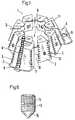
- Fig. 1
- Zeigt in räumlicher Darstellung eine Hülse als Grundkörper, auf dem zwei Stützkörper fixiert sind;
- Fig. 2a bis 2c
- gibt eine erste Ausführungsform eines Stützkörpers wieder, wobei 2a eine Seitenansicht ist, 2b einen Schnitt B-B von 2a darstellt, und 2c eine Aufsicht auf die der Basis des Kegelstumpfes zugeordnete Stirnfläche von 2a in Richtung des gezeigten Pfeiles C wiedergibt;
- Fig. 3a und 3b, sowie 4a und 4b
- sind zwei weitere Beispiele für unterschiedliche Stützkörper, wobei 3a und 4a die Schnitte A-A von 3b bzw. 4b sind, während diese beiden Teilfiguren der Figur 2c entsprechende Aufsichten darstellen;
- Fig. 5a und 5b
- sind den Figuren 2a und 2c entsprechende Darstellungen eines weiteren Stützkörpers;
- Fig. 6
- schliesslich zeigt ein vergrössertes Beispiel einer als Fixierungselement dienenden Stiftschraube.
- Fig. 1
- Shows a spatial representation of a sleeve as a base body, on which two support bodies are fixed;
- 2a to 2c
- shows a first embodiment of a support body, wherein FIG. 2a is a side view, FIG. 2b shows a section BB from FIG. 2a, and FIG. 2c shows a view of the one assigned to the base of the truncated cone End face of 2a in the direction of the arrow C shown;
- 3a and 3b, and 4a and 4b
- are two further examples of different support bodies, wherein 3a and 4a are the sections AA of 3b and 4b, respectively, while these two partial figures of FIG. 2c represent corresponding views;
- 5a and 5b
- FIGS. 2a and 2c are representations of a further support body;
- Fig. 6
- finally shows an enlarged example of a stud screw serving as a fixing element.
Die aus Metall, beispielsweise aus Titan oder einer Titanlegierung, gefertigte Hülse 1 ist in ihrer Grundform ein Kegelstumpf und besteht in Umfangsrichtung alternierend aus Bereichen 3 grösserer Wandstärke D und Bereichen 4 geringerer Wandstärke d, die Kreisringsektoren mit parallele Wänden bilden. Weiterhin weisen die Bereiche 4 von beiden Stirnseiten des Kegelstumpfes her Ausnehmungen 10 auf, durch die ihre Flexibilität erhöht wird.The sleeve 1 made of metal, for example titanium or a titanium alloy, is in its basic form a truncated cone and in the circumferential direction alternately consists of regions 3 of greater wall thickness D and regions 4 of reduced wall thickness d, which form circular ring sectors with parallel walls. Furthermore, the areas 4 have
Wie in dem gezeigten Ausführungsbeispiel einer Hülse 1 kann diese darüberhinaus längs einer Mantellinie über ihre ganze Höhe geschlitzt sein, was die Flexibilität und Elastizität der Hülse 1 ebenfalls vergrössert.As in the exemplary embodiment shown, a sleeve 1 can furthermore be slit along a surface line over its entire height, which also increases the flexibility and elasticity of the sleeve 1.
Darüberhinaus sind die Bereiche 3 grösserer Wandstärke D aussen durch eine Querverzahnung 5 in Umfangsrichtung strukturiert, was das An- und Einwachsen von Knochengewebe fördert.In addition, the areas 3 of greater wall thickness D are on the outside through
Die Bereiche 3 grösserer Wandstärke D sind im Querschnitt trapezförmig und von der Kegelstumpfbasis zum Pol hin konisch zulaufend, wodurch sie Gleitschuhe für sie schwalbenschwanz-ähnlich umgreifende Stützkörper 11 bilden, die vom Pol her auf die Bereiche 3 aufschiebbar sind. Die Stützkörper 11 sind dabei mit Vorteil in ihrer Länge längs einer Mantellinie derart an die Hülse 1 angepasst, dass die Stirnseiten beider bei montiertem Stützkörper 11 mindestens annähernd bündig sind.The areas 3 of greater wall thickness D are trapezoidal in cross-section and taper from the truncated cone base to the pole, as a result of which they form sliding shoes for
Jeder Bereich 3 ist in Radialrichtung von einer Gewindebohrung 12 durchsetzt, in die eine mit einem Gewinde 14 versehene Stiftschraube 13 (Fig. 6) als Fixierungs- und gleichzeitig als Zentrierelement für einen Stützkörper 11 von der Innenseite der Hülse 1 her eingeschraubt wird.Each area 3 is penetrated in the radial direction by a threaded
Für eine genaue Positionierung und Zentrierung des Stützkörpers 11 weist die Stiftschraube 13 (Fig. 6) eine kegelförmige Zentrierspitze 15 auf, die in eine daran angepasste, hohlkegelige Ausnehmung 16 (siehe z.B. Fig. 2b) eines Stützkörpers 11 eindringt.For exact positioning and centering of the
Wie bereits erwähnt kann jeder Hülse 1 eine ganze Anzahl Stützkörper 11 mit unterschiedlichen Abmessungen und Formen zugeordnet sein. Der einfachste Stützkörper 11 (Fig. 2) ist ein viereckiger Körper mit ebenfalls trapezförmigem Querschnitt; aus diesem Körper ist eine in Form und Abmessungen an den Bereich grösserer Wandstärke D oder Gleitschuh 3 der Hülse 1 mit kleinem toleranzenbedingtem Spiel angepasste schwalbenschwanzähnliche Ausnehmung 17 (Fig. 2b) herausgearbeitet, mit der der Stützkörper 11 den Gleitschuh umgreift. Die bei verschiedenen Stützkörpern 11 unterschiedliche Dicke in Radialrichtung - vergleiche z. Beispiel Fig. 3a und 4a - ist in allen Beispielen mit a bezeichnet.As already mentioned, a whole number of
Bei dem Stützkörper nach Fig. 3 ist die einfache Form nach Fig. 2 an der basisseitigen Stirnfläche durch eine Lasche 6 ergänzt, die eine leicht gewölbte Form besitzt; in ihr ist eine Durchtrittsbohrung 9 vorgesehen, für den Durchtritt einer Knochenschraube 8 (Fig. 1).In the support body according to FIG. 3, the simple shape according to FIG. 2 is supplemented on the base-side end face by a
Der Stützkörper 11 nach Fig. 4 unterscheidet sich von den beiden vorhergehenden zum einen durch seine grössere Dicke a und zum anderen dadurch, dass seine Lasche 7, die ebenfalls eine Bohrung 9 aufweist, eben ist und unter einem anderen Winkel an den Stützkörper 11 angesetzt ist als die Lasche 6.The
Bei dem letzten gezeigten Beispiel eines Stützkörpers 11 ist seine Dicke a in radialer Richtung über die Mantelhöhe nicht konstant, sondern stufenförmig abgesetzt, wobei die grössere Dicke bei montiertem Stützkörper zur Polseite des Kegelstumpfes der Hülse 1 zu liegen kommt.In the last example of a supporting
Wie die Mantelflächen der Bereiche 3 der Hülse 1 können auch die Mantelflächen der Stützkörper 11 mit einer Querverzahnung 5 (Fig. 1) versehen sein, um das An- und/oder Einwachsen von Knochengewebe zu fördern.Like the lateral surfaces of the regions 3 of the sleeve 1, the lateral surfaces of the
Selbstverständlich sind sowohl für die Stützkörper als auch für ihre Verbindung mit der Hülse und für ihre Fixierung und Zentrierung andere Formen und Konstruktionen möglich, wie z. Beispiel Doppellaschen oder andere, den individuellen Verhältnissen des Acetabulums angepasste Formen.Of course, other shapes and constructions are possible both for the support body and for their connection to the sleeve and for their fixing and centering, such as. For example double straps or other shapes adapted to the individual conditions of the acetabulum.
Claims (9)
- A two-part hipjoint socket for anchoring in the pelvic bone, consisting of a frustoconical shell (1) and an insert which contains the actual cup of the socket and may be pressed with a snug fit into the hollow inside the shell (1), the shell (1) being manufactured from metal and exhibiting regions (3) of greater wall thickness (D) which alternate in the circumferential direction with regions (4) having less wall thickness (d) and further the regions (4) having less thickness of wall (d) are in cross-section sectors of a circular ring, whilst the regions (3) of greater wall thickness (D) have a cross-section essentially trapezoidal which tapers in conically towards the pole, characterized in that the regions (3) of greater wall thickness (D) are made as guideshoes extending along the surface of the truncated cone for supporting bodies (11) which may be slipped on externally, and that each of these regions (3) is provided with fixing members (13) for these supporting bodies (11).
- A hipjoint socket as in Claim 1, characterized in that the supporting bodies (11) have recesses (17) like dovetails which embrace the trapezoidal cross-section of the regions (3) and may be slipped onto the guideshoes from the pole.
- A hipjoint socket as in Claim 1 or 2, characterized in that supporting bodies (11) are provided of different thicknesses (a).
- A hipjoint socket as in one of the Claims 1 to 3, characterized in that at least some of the supporting bodies (11) are provided at their ends next the base of the truncated cone with flaps (6, 7) pointing outwards.
- A hipjoint socket as in Claim 4, characterized in that the flaps (6, 7) are provided with holes (9) drilled in them for bone screws (8) to pass through.
- A hipjoint socket as in one of the Claims 1 to 5, characterized in that the thickness (a) of the supporting bodies (11) in the radial direction increases or decreases steadily from their ends next the base or in the form of a step.
- A hipjoint socket as in one of the Claims 1 to 6, characterized in that the regions (3) of the shell (1) having greater wall thickness (D) and/or the supporting bodies (11) are provided on their outer surfaces with sets of transverse teeth (5).
- A hipjoint socket as in one of the Claims 1 to 7, characterized in that the fixing members (13) are made as setscrews (13) which have conical centreing tips (15) and pass through the regions (3) of greater wall thickness (D).
- A hipjoint socket as in Claim 8, characterized in that the setscrews (13) engage in the supporting bodies (11) in hollow conical recesses (16) adapted to their centreing tips (15).
Applications Claiming Priority (2)
| Application Number | Priority Date | Filing Date | Title |
|---|---|---|---|
| CH11292 | 1992-01-16 | ||
| CH112/92 | 1992-01-16 |
Publications (2)
| Publication Number | Publication Date |
|---|---|
| EP0551794A1 EP0551794A1 (en) | 1993-07-21 |
| EP0551794B1true EP0551794B1 (en) | 1996-01-24 |
Family
ID=4179537
Family Applications (1)
| Application Number | Title | Priority Date | Filing Date |
|---|---|---|---|
| EP92810988AExpired - LifetimeEP0551794B1 (en) | 1992-01-16 | 1992-12-11 | Two-part acetabular cup |
Country Status (4)
| Country | Link |
|---|---|
| US (1) | US5549692A (en) |
| EP (1) | EP0551794B1 (en) |
| AT (1) | ATE133327T1 (en) |
| DE (1) | DE59205174D1 (en) |
Cited By (7)
| Publication number | Priority date | Publication date | Assignee | Title |
|---|---|---|---|---|
| US7597715B2 (en) | 2005-04-21 | 2009-10-06 | Biomet Manufacturing Corp. | Method and apparatus for use of porous implants |
| US7635447B2 (en) | 2006-02-17 | 2009-12-22 | Biomet Manufacturing Corp. | Method and apparatus for forming porous metal implants |
| US8021432B2 (en) | 2005-12-05 | 2011-09-20 | Biomet Manufacturing Corp. | Apparatus for use of porous implants |
| US8066778B2 (en) | 2005-04-21 | 2011-11-29 | Biomet Manufacturing Corp. | Porous metal cup with cobalt bearing surface |
| US8123814B2 (en) | 2001-02-23 | 2012-02-28 | Biomet Manufacturing Corp. | Method and appartus for acetabular reconstruction |
| US8266780B2 (en) | 2005-04-21 | 2012-09-18 | Biomet Manufacturing Corp. | Method and apparatus for use of porous implants |
| US8292967B2 (en) | 2005-04-21 | 2012-10-23 | Biomet Manufacturing Corp. | Method and apparatus for use of porous implants |
Families Citing this family (36)
| Publication number | Priority date | Publication date | Assignee | Title |
|---|---|---|---|---|
| EP0640324B1 (en)* | 1993-08-30 | 1998-05-20 | Sulzer Orthopädie AG | Artificial acetubular cup |
| US7476254B2 (en)* | 1993-11-01 | 2009-01-13 | Biomet Manufacturing Corporation | Compliant fixation for pelvis |
| US7670383B1 (en) | 2004-05-04 | 2010-03-02 | Biomet Manufacturing Corp. | Pubic catch |
| US7722678B2 (en)* | 1993-11-01 | 2010-05-25 | Biomet Manufacturing Corp. | Intramedullary compliant fixation |
| DE4444510A1 (en)* | 1994-11-30 | 1996-06-05 | Guenter Prof Dr Med Lob | Fastener for osteosynthesis |
| FR2729560B1 (en)* | 1995-01-20 | 1997-04-18 | Medinov Sa | GAME OF FEMALE SHIMS, PARTICULARLY FOR THREE-COMPARTMENTAL KNEE RECOVERY PROSTHESIS |
| FR2740327B1 (en)* | 1995-10-27 | 1998-01-23 | Cedior | SHIM FOR RECOVERY PROSTHESIS COMPONENT |
| GB2323036B (en)* | 1997-03-14 | 2001-04-11 | Finsbury | Prosthetic implant and surgical tool |
| DE19730073C1 (en)* | 1997-07-14 | 1999-07-15 | Jansson Volkmar Priv Doz Dr Me | Endoprosthesis system |
| FR2775586B1 (en)* | 1998-03-03 | 2000-06-30 | Tornier Sa | MODULAR ACETABULAR OR COTYLOID IMPLANT |
| FR2785522A1 (en)* | 1998-11-09 | 2000-05-12 | Nort On | Hip joint prosthesis has socket cup and metallic ring with angularly adjustable liner insert |
| DE19926923A1 (en) | 1999-06-14 | 2000-12-21 | Ceramtec Ag | Modular socket for a ball joint prosthesis |
| US7291177B2 (en) | 2001-02-23 | 2007-11-06 | Biomet Manufacturing Corp. | Method and apparatus for acetabular reconstruction |
| US7713306B2 (en) | 2001-02-23 | 2010-05-11 | Biomet Manufacturing Corp. | Method and apparatus for acetabular reconstruction |
| US6458161B1 (en)* | 2001-02-23 | 2002-10-01 | Biomet, Inc. | Method and apparatus for acetabular reconstruction |
| FR2827503B1 (en)* | 2001-07-23 | 2003-10-24 | Macara Frederique | MODULAR RECONSTRUCTION COTYLE |
| FR2833155B1 (en)* | 2001-12-06 | 2004-08-27 | Chirurgicale D Aide A La Rech | COTYL FOR HIP PROSTHESIS BALL JOINT OR THE LIKE |
| IL148596A0 (en)* | 2002-03-10 | 2002-09-12 | Orthoscope Ltd | Improved socket prosthesis |
| GB0207170D0 (en) | 2002-03-26 | 2002-05-08 | Mcminn Derek J W | Hip joint prosthesis |
| GB0313444D0 (en)* | 2003-06-11 | 2003-07-16 | Midland Medical Technologies L | Modular dysplasia cup |
| US7050354B2 (en)* | 2003-12-16 | 2006-05-23 | Freescale Semiconductor, Inc. | Low-power compiler-programmable memory with fast access timing |
| US7942880B2 (en)* | 2004-02-18 | 2011-05-17 | Bertram Iii Morton | Geometric replacements for defective bone |
| US8048166B2 (en)* | 2004-05-04 | 2011-11-01 | Biomet Manufacturing Corp. | Method and apparatus for constructing a modular acetabulum |
| US8500744B2 (en)* | 2005-05-12 | 2013-08-06 | Finsbury (Development) Limited | Cap and activation tool |
| US20080021568A1 (en)* | 2006-07-07 | 2008-01-24 | Howmedica Osteonics Corp. | Acetabular cup augment system |
| US7993408B2 (en)* | 2008-02-12 | 2011-08-09 | Biomet Manufacturing Corp. | Acetabular cup having an adjustable modular augment |
| US9820853B2 (en)* | 2009-05-06 | 2017-11-21 | Biomet Manufacturing, Llc | Acetabular cup system |
| AU2010269163B2 (en)* | 2009-07-10 | 2016-04-21 | Implantica Patent Ltd. | Hip joint device and method |
| US20110178604A1 (en)* | 2010-01-18 | 2011-07-21 | Biomet Manufacturing Corp. | Expandable Endoprosthesis |
| US8968415B2 (en) | 2012-02-07 | 2015-03-03 | Biomet Manufacturing, Llc | Implant fixation device |
| US8915970B2 (en) | 2013-02-08 | 2014-12-23 | Biomet Manufacturing, Llc | Transdermal prosthesis |
| US20160158015A1 (en)* | 2014-12-04 | 2016-06-09 | Stemmed Implant Technology Inc. | Bone implant |
| US12053384B2 (en)* | 2015-02-27 | 2024-08-06 | Idr-Biomed Ltd | Buffer for femoral head and neck excision |
| US10456262B2 (en) | 2016-08-02 | 2019-10-29 | Howmedica Osteonics Corp. | Patient-specific implant flanges with bone side porous ridges |
| US10695183B2 (en)* | 2017-03-14 | 2020-06-30 | Charles L. Nelson | Augments and methods of implanting augments |
| US12310638B2 (en) | 2021-05-07 | 2025-05-27 | Atul F. Kamath | Modular bone reinforcement |
Family Cites Families (10)
| Publication number | Priority date | Publication date | Assignee | Title |
|---|---|---|---|---|
| DE8204299U1 (en)* | 1982-02-12 | 1983-06-16 | Mecron Medizinische Produkte Gmbh, 1000 Berlin | ANCHORING AGENT FOR AN ARTIFICIAL PAN |
| SU1123682A1 (en)* | 1983-02-23 | 1984-11-15 | Саратовский Ордена Трудового Красного Знамени Государственный Медицинский Институт | Endoprosthesis of colytoid cavity |
| FR2578162A1 (en)* | 1985-03-04 | 1986-09-05 | Rambert Andre | Cup for total prosthesis of the hip or of the shoulder |
| HU192924B (en)* | 1985-03-29 | 1987-08-28 | Gabor Tari | Adhesiveless acetabulum particularly for hip prothesis and device for fixing the acetabulum |
| FR2633509A1 (en)* | 1988-07-04 | 1990-01-05 | Louyot Comptoir Lyon Alemand | Femoral component for hip prostheses |
| CH675823A5 (en)* | 1988-08-24 | 1990-11-15 | Sulzer Ag | |
| SU1627171A1 (en)* | 1988-11-24 | 1991-02-15 | Б. Г. Зимлицкий и Е. Д. Соломко | Wedge-shaped endoprosthesis of the hip joint acetabulum |
| DE3918970A1 (en)* | 1989-06-12 | 1990-12-13 | Eska Medical Gmbh & Co | IMPLANTATION KIT |
| US5176711A (en)* | 1991-03-06 | 1993-01-05 | Grimes James B | Acetabular revision system |
| US5192329A (en)* | 1991-03-07 | 1993-03-09 | Joint Medical Products Corporation | Oblong acetabular cup |
- 1992
- 1992-12-11DEDE59205174Tpatent/DE59205174D1/ennot_activeExpired - Fee Related
- 1992-12-11EPEP92810988Apatent/EP0551794B1/ennot_activeExpired - Lifetime
- 1992-12-11ATAT92810988Tpatent/ATE133327T1/ennot_activeIP Right Cessation
- 1994
- 1994-06-08USUS08/257,214patent/US5549692A/ennot_activeExpired - Fee Related
Cited By (10)
| Publication number | Priority date | Publication date | Assignee | Title |
|---|---|---|---|---|
| US8123814B2 (en) | 2001-02-23 | 2012-02-28 | Biomet Manufacturing Corp. | Method and appartus for acetabular reconstruction |
| US8551181B2 (en) | 2001-02-23 | 2013-10-08 | Biomet Manufacturing, Llc | Method and apparatus for acetabular reconstruction |
| US9375316B2 (en) | 2001-02-23 | 2016-06-28 | Biomet Manufacturing, Llc. | Method and apparatus for acetabular reconstruction |
| US7597715B2 (en) | 2005-04-21 | 2009-10-06 | Biomet Manufacturing Corp. | Method and apparatus for use of porous implants |
| US8066778B2 (en) | 2005-04-21 | 2011-11-29 | Biomet Manufacturing Corp. | Porous metal cup with cobalt bearing surface |
| US8197550B2 (en) | 2005-04-21 | 2012-06-12 | Biomet Manufacturing Corp. | Method and apparatus for use of porous implants |
| US8266780B2 (en) | 2005-04-21 | 2012-09-18 | Biomet Manufacturing Corp. | Method and apparatus for use of porous implants |
| US8292967B2 (en) | 2005-04-21 | 2012-10-23 | Biomet Manufacturing Corp. | Method and apparatus for use of porous implants |
| US8021432B2 (en) | 2005-12-05 | 2011-09-20 | Biomet Manufacturing Corp. | Apparatus for use of porous implants |
| US7635447B2 (en) | 2006-02-17 | 2009-12-22 | Biomet Manufacturing Corp. | Method and apparatus for forming porous metal implants |
Also Published As
| Publication number | Publication date |
|---|---|
| US5549692A (en) | 1996-08-27 |
| DE59205174D1 (en) | 1996-03-07 |
| EP0551794A1 (en) | 1993-07-21 |
| ATE133327T1 (en) | 1996-02-15 |
Similar Documents
| Publication | Publication Date | Title |
|---|---|---|
| EP0551794B1 (en) | Two-part acetabular cup | |
| EP0340159B1 (en) | Dowel pin for cementless bone implants | |
| DE69628352T2 (en) | Zwischenwirbelfusionierungseinrichtung | |
| EP0083708B1 (en) | Acetabular cup to be anchored in the pelvis without cement | |
| EP0586335A1 (en) | Two-piece acetabular cup | |
| EP0085147B1 (en) | Straight flat shaft for a joint endoprosthesis | |
| EP0622056A2 (en) | Implantable anchoring organ for receiving prostheses and the like | |
| DE2611985A1 (en) | Hip head endoprosthesis | |
| DE19731442A1 (en) | Cup for a joint endoprosthesis | |
| EP0328848A1 (en) | Reticular reinforcement for anchoring a prosthesis stem | |
| EP1100396A1 (en) | Implant for holding and/or forming a dental prosthesis or artificial finger joint | |
| DE8903850U1 (en) | Thigh part for a hip endoprosthesis | |
| EP0494476A1 (en) | Shaft prosthesis | |
| EP0601224B1 (en) | Fixation shell for receiving the cup body of an artificial acetabular cup | |
| EP1168989B1 (en) | Condyle prosthesis and kit for producing same | |
| CH674708A5 (en) | ||
| EP0321389A1 (en) | Implantable prosthesis | |
| EP1276440B1 (en) | Femoral neck prosthesis | |
| DE3426947A1 (en) | Self-adhesive, cementless implantable hip implant | |
| EP0339320B1 (en) | Shaft for a prosthesis | |
| WO2007124607A1 (en) | Shaft for a joint prosthesis | |
| DE10118985C2 (en) | Acetabular system | |
| DE3923154C2 (en) | ||
| DE4211347C2 (en) | Cup for a hip joint endoprosthesis | |
| DE60037398T2 (en) | REINFORCEMBLING CONNECTING SCREW FOR THE ARTHRODESIS OF A BONE JOINT, ESPECIALLY FOR THE STABILIZATION OF TWO SPINS |
Legal Events
| Date | Code | Title | Description |
|---|---|---|---|
| PUAI | Public reference made under article 153(3) epc to a published international application that has entered the european phase | Free format text:ORIGINAL CODE: 0009012 | |
| AK | Designated contracting states | Kind code of ref document:A1 Designated state(s):AT CH DE FR GB IT LI | |
| 17P | Request for examination filed | Effective date:19931116 | |
| 17Q | First examination report despatched | Effective date:19950531 | |
| GRAA | (expected) grant | Free format text:ORIGINAL CODE: 0009210 | |
| AK | Designated contracting states | Kind code of ref document:B1 Designated state(s):AT CH DE FR GB IT LI | |
| REF | Corresponds to: | Ref document number:133327 Country of ref document:AT Date of ref document:19960215 Kind code of ref document:T | |
| GBT | Gb: translation of ep patent filed (gb section 77(6)(a)/1977) | Effective date:19960123 | |
| REF | Corresponds to: | Ref document number:59205174 Country of ref document:DE Date of ref document:19960307 | |
| REG | Reference to a national code | Ref country code:CH Ref legal event code:NV Representative=s name:SULZER MANAGEMENT AG | |
| ITF | It: translation for a ep patent filed | ||
| ET | Fr: translation filed | ||
| PLBE | No opposition filed within time limit | Free format text:ORIGINAL CODE: 0009261 | |
| 26N | No opposition filed | ||
| PGFP | Annual fee paid to national office [announced via postgrant information from national office to epo] | Ref country code:GB Payment date:20011116 Year of fee payment:10 | |
| PGFP | Annual fee paid to national office [announced via postgrant information from national office to epo] | Ref country code:CH Payment date:20011120 Year of fee payment:10 | |
| PGFP | Annual fee paid to national office [announced via postgrant information from national office to epo] | Ref country code:AT Payment date:20011203 Year of fee payment:10 | |
| PGFP | Annual fee paid to national office [announced via postgrant information from national office to epo] | Ref country code:DE Payment date:20011208 Year of fee payment:10 | |
| PGFP | Annual fee paid to national office [announced via postgrant information from national office to epo] | Ref country code:FR Payment date:20011211 Year of fee payment:10 | |
| REG | Reference to a national code | Ref country code:GB Ref legal event code:IF02 | |
| PG25 | Lapsed in a contracting state [announced via postgrant information from national office to epo] | Ref country code:GB Free format text:LAPSE BECAUSE OF NON-PAYMENT OF DUE FEES Effective date:20021211 Ref country code:AT Free format text:LAPSE BECAUSE OF NON-PAYMENT OF DUE FEES Effective date:20021211 | |
| PG25 | Lapsed in a contracting state [announced via postgrant information from national office to epo] | Ref country code:LI Free format text:LAPSE BECAUSE OF NON-PAYMENT OF DUE FEES Effective date:20021231 Ref country code:CH Free format text:LAPSE BECAUSE OF NON-PAYMENT OF DUE FEES Effective date:20021231 | |
| PG25 | Lapsed in a contracting state [announced via postgrant information from national office to epo] | Ref country code:DE Free format text:LAPSE BECAUSE OF NON-PAYMENT OF DUE FEES Effective date:20030701 | |
| GBPC | Gb: european patent ceased through non-payment of renewal fee | ||
| REG | Reference to a national code | Ref country code:CH Ref legal event code:PL | |
| PG25 | Lapsed in a contracting state [announced via postgrant information from national office to epo] | Ref country code:FR Free format text:LAPSE BECAUSE OF NON-PAYMENT OF DUE FEES Effective date:20030901 | |
| REG | Reference to a national code | Ref country code:FR Ref legal event code:ST | |
| PG25 | Lapsed in a contracting state [announced via postgrant information from national office to epo] | Ref country code:IT Free format text:LAPSE BECAUSE OF NON-PAYMENT OF DUE FEES;WARNING: LAPSES OF ITALIAN PATENTS WITH EFFECTIVE DATE BEFORE 2007 MAY HAVE OCCURRED AT ANY TIME BEFORE 2007. THE CORRECT EFFECTIVE DATE MAY BE DIFFERENT FROM THE ONE RECORDED. Effective date:20051211 |