EP0551572B1 - Tibial resector guide - Google Patents
Tibial resector guideDownload PDFInfo
- Publication number
- EP0551572B1 EP0551572B1EP92117582AEP92117582AEP0551572B1EP 0551572 B1EP0551572 B1EP 0551572B1EP 92117582 AEP92117582 AEP 92117582AEP 92117582 AEP92117582 AEP 92117582AEP 0551572 B1EP0551572 B1EP 0551572B1
- Authority
- EP
- European Patent Office
- Prior art keywords
- rod
- guide
- slide
- resector
- head
- Prior art date
- Legal status (The legal status is an assumption and is not a legal conclusion. Google has not performed a legal analysis and makes no representation as to the accuracy of the status listed.)
- Expired - Lifetime
Links
Images


Classifications
- A—HUMAN NECESSITIES
- A61—MEDICAL OR VETERINARY SCIENCE; HYGIENE
- A61B—DIAGNOSIS; SURGERY; IDENTIFICATION
- A61B17/00—Surgical instruments, devices or methods
- A61B17/14—Surgical saws
- A61B17/15—Guides therefor
- A61B17/154—Guides therefor for preparing bone for knee prosthesis
- A61B17/157—Cutting tibia
Definitions
- This inventionrelates to resector guides as used in orthopaedic surgery and has specific relevance to a tibial resector guide having a guide head which may be selectively angled in an anterior-posterior plane.
- proximal end of the tibiamust be cut to accommodate the tibial implant. Proper fit and function of the knee prosthesis will depend in large part on the accuracy of the tibial cut. Therefore, it is not uncommon for a surgeon to place a cutting guide in close proximity with the proximal end of the tibia.
- Prior art cutting guidestypically include a head which accommodates the bone saw blade. The surgeon passes the saw blade along the guide head to resect a proximal portion of the tibia.
- Tibial resector guidesin general, are not new. A number of such guides have been developed and patented throughout the years.
- the Woolson patent U.S. 4,841,975discloses a tibial resector guide having a telescoplng rod carrying a cutting head at its upper end.
- the cutting guideis adjustable relative to the telescoping rod by a pair of oppositely positioned thumb screws.
- the guidemay be aligned with the mechanical axis of the joint by use of a slidable plate.
- U.S. Patent No. 4,736,737discloses a tibial resector head connected to an intramedullary rod and shiftable in a longitudinal direction only. Angular adjustment is not provided.
- PetersenU.S. Patent No. 4,773,407, discloses an instrument for guiding the resection of a distal femur having a head which is pivotally carried by a guide rod.
- the pivotal headis for the purpose of providing alignment and not posterior slope.
- the guide rodcarries a rotating rod having holes therethrough for accommodating a securement pin.
- EP-A-415 837concerns a tibial resector guide according to the features of the preamble of Claim 1. Adjustment of the cutting head is via a pin which passes through one of a variety of positions in the head into the tibial support.
- This inventionprovides for a tibial resector guide having an angularly adjustable head controlled by a thumb actuated slide mechanism as recited in claim 1.
- the headmay be positioned in a plurality of predetermined angular orientations in the anterior-posterior plane.
- the head guideincludes angled side walls which permit the guide to have a narrow anterior aperture yet allow the saw blade to completely pass through the tibia.
- the tibial resector of this inventionincludes a length adjustment mechanism on the head for providing small height adjustments for positioning the cutting guide.
- the length adjustment memberincludes an enlarged thumb wheel for ease of operation.
- a pinning forkis pivotally connected to the adjustment member and extends upwardly adjacent the cutting guide.
- the pinning forkpermits the surgeon to pin the upper end of the instrument to the patient's leg preventing movement of the instrument during resection.
- the cutting guidemay be further adjusted in height by rotating the length mechanism.
- the resector guidefurther includes a sliding ankle adjustment to provide proper alignment of the guide with the mechanical axis of the joint.
- Another object of the inventionis to provide an adjustable resector guide head.
- Another object of the inventionis to provide for a tibial resector having a height adjustment member for providing small increments in height.
- Still another object of this inventionis to provide for a tibial resector guide having a narrow aperture cutting guide with outwardly inclined side walls to provide an enlarged cutting area.
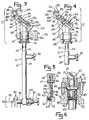
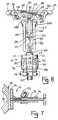
- tibial resector guide 10includes a head 12 and an ankle adjustment mechanism 14 interconnected by a telescoping rod 16.
- Rod 16is adjustable in length and is maintained at a fixed position by turning thumb wheel 18 to cause a screw (not shown) to engage the inner rod 20.
- Inner rod 20includes a flattened side 22 for contact with the screw (not shown) to prevent rotation of inner rod 20 relative to outer tube 24.
- the distal tip of inner rod 20includes a transverse bore 21.
- Head 12includes a cutting guide 26 having upper and lower walls 30, 32 and side walls 34 defining a slot 28 for accommodating the blade of a bone saw (not shown).
- An arcuate recessis formed in the posterior side of upper and lower walls 30, 32 for accommodating the proximal portion of a patient's lower leg adjacent the knee joint.
- Side walls 34 of the guidediverge from the anterior side toward the posterior side of the upper and lower walls such that the opening of slot 28 on the anterior side of the guide is longitudinally smaller than the opening of the slot on the posterior side of guide 26. This feature permits the use of a full stroke cutting guide 26 allowing the entire tibia to be cut through in one pass within the confined area of the surgical site.
- a plurality of pinning apertures 36are provided extending from the bottom surface of the guide 26. Pinning apertures 36 accommodate a fixation pin during surgery to secure guide 10 against movement during resection.
- a pair of legs 38extend at an angle from lower wall 32 of guide 26 and each include through bores 37, 39.
- Head 12further includes a posterior slope adjustment mechanism 40 for selectively angling the cutting guide 26 relative to rod 16.
- Slope adjustment mechanism 40includes a fixed body 42 having a downwardly extending leg 44. The distal portion of leg 44 includes screw threads 45.
- a longitudinally aligned slot 43is formed through leg 44 and threads 43.
- a central blind bore 47extends inwardly into leg 44.
- Body 42is longitudinal in dimension and has a dovetail slot 46 formed in one side wall thereof.
- a plurality of indentions 48are formed in the inner wall of the dovetail slot.
- a slot 50is formed through body 42 in communication with dovetail slot 46.
- Body 42terminates in a protrusion 52 having a bore therethrough.
- Slope adjustment mechanism 48further includes a slide 54 accommodated within dovetail slot 46 and slidable between a fully retracted position of Figs 1, 2, 3, and 8 and the fully extended position of Fig. 4.
- Slide 54includes a slot 56 positioned at an angle with the slide as illustrated.
- a thumb bar 58extends outwardly from slide 54 to provide access to the user.
- slide 54includes a blind bore 60 which carries a helical spring 62 and a ball stop 64.
- spring 62urges ball stop against the inner wall of dovetail slot 46.
- ball stop 64seats within indentations 48 to impart a positive snap feel to the slide.
- Guide 26is pivotally connected to the slope adjustment mechanism by a screw 68 press threaded through a pair of aligned openings in legs 38 of guide 26 and the bore of knob 52.
- a screw 66interconnects the distal ends of legs 38 and is accommodated within slot 56 of slide 54 and slot 50 of fixed body 42. As slide 54 is shifted between its extreme positions, screw 66 rides within the angled slot 56 causing the cutting guide 26 to pivot about pin 68 to thereby vary the angle of inclination of the slot 28 relative to the fixed body 42.
- Head 12also includes a length adjustment mechanism 70 which provides small adjustments in the overall length of the tibia resector guide 10.
- Length adjustment mechanism 70(hereinafter referred to as LAM 70) includes a cap 72 having a lower depending shaft with external threads and a central bore dimensioned to loosely accommodate leg 44.
- LAM 70further includes a cylindrical body 74 having a central longitudinal bore stepped in diameter to threadibly accommodate cap 72 at one end and leg 44 at the opposite end. As cylindrical body 74 rotates relative to leg 44, body 74 travels along threads 45 of leg 44.
- the lower depending shaft of cap 72 and the central bore of cylindrical body 74are formed such that when cap 72 is fully screwed into cylindrical body, a ring shaped cavity 76 is formed therebetween.
- the distal end of inner rod 20is slidably positioned within the central blind bore 47 of leg 44.
- a pin 78is inserted into bore 21 of rod 20 and extends outwardly therefrom for slidable accommodation within slot 43 of
- head 12includes a pinning fork 80 pivotally connected to a collar 82 loosely carried by cylindrical body 74 such that the collar remains rotationally stationary as body 74 rotates.
- Pinning fork 80is slightly arcuate in its side view and includes a pair of arms 86 each of which terminate in a pinning tube 88. Arms 86 are positioned laterally adjacent legs 38 of cutting guide 26. The distal ends of arms 86 are accommodated within recesses formed in the underneath side of lower wall 32 as shown.
- Ankle adjustment mechanism 14includes an ankle contacting member 90 slidably carried by the foot 94 of a shaft 92.
- a threaded rod 96is accommodated within shaft 92 and causes a restrictive interference between member 90 and foot 94 when rod 96 is rotatably extended toward member 90.
- Member 90includes a pair of legs 98 spaced from one another for straddling the patients ankle.
- Shaft 92is carried by outer tube 24 or telescoping rod 16 and is selectively lockable in position relative to tube 24 by an interfering locking device 100.
- tibial resector guide 10is positioned adjacent the patient's lower leg such that ankle adjustment mechanism 14 is adjacent the patient's ankle with legs 98 straddling the ankle.
- Thumb wheel 18is rotated to release inner rod 16 and the head 12 is positioned in such that cutting guide 26 is in the approximate position for the tibial cut predetermined by the surgeon.
- the ankle adjustment mechanism 14is adjusted so as to align device 10 with the mechanical axis of the knee joint for proper installation of the tibial component.
- Telescoping rod 16is positioned in parallel with the tibia. The particular reasons for adjusting the ankle adjusting mechanism 14 are well known in the industry and need not be discussed here.
- the surgeonmay insert a stabilizing pin through each pinning tube 88 of the pinning fork and into the tibia.
- each longitudinal end of pin 78is seated within the ring-like cavity formed between cap 72 and body 74 of LAM 70 with the remaining portion of the pin carried within bore 21 of inner rod 20.
- Pin 78acts as an anchor to longitudinally fix the combination of cylindrical body 74 and cap 72 to inner rod 20. Therefore, with leg 44 threadibly accommodated within cylindrical body 74, rotation of cylindrical body 74 causes leg 44 to travel longitudinally within the cylindrical body 74.
- Pin 78 accommodated within slot 43 of leg 44defines the longitudinal extremes the leg's shifting relative to rod 20. A longitudinal shift in leg 44 shifts cutting guide 26 relative to rod 20 thereby changing the overall length of the tibial resector guide 10.
- the telescoping rod 16may be used by the surgeon to set the cutting guide in the approximate location for the cut.
- the length adjustment mechanismmay then be used to precisely align the cutting guide 26 with the desired cut line. This precise alignment is possible due to the interplay of the cylindrical body 74, pin 78 and leg 44.
- the threaded adjustment of the resector lengthprovides for infinite and precise adjustment of the cutting guide 26.
- leg 44may include indicia which may be referenced against the top of cap 72 to provide visual indication of the amount of movement of the leg relative to rod 20. Preferably, the indicia will be spaced in 2mm increments.
- the anterior-posterior (A-P) angle of the cutting guide 26may be altered relative to telescoping rod 16 by adjustment of the slope adjustment mechanism 40.
- the surgeonshifts slide 54 relative to fixed body 42 within the dovetail groove 46.
- screw 66(accommodated within the angled slot 56 of slide 54) follows slot 54 which translates into a vertical motion within slot 50 of fixed body 42.
- This vertical movement of screw 66 connected to the distal ends of legs 38causes the cutting guide 26 to pivot about pivot pin 68 thereby causing a change in the A-P slope of the cutting guide 26 and more importantly, slot 28.
- each indentationcorresponds to a particular angular setting of the cutting head as is indicated by indicia on the upper surface of the fixed body as shown in the figures.
- the indentationscorrelate to O, 3, 5, 7 and 10 degrees of A-P slope relative to the telescoping rod 16. Since the angles of slope adjustment mechanism 40 are referenced from the telescoping rod it is imperative that the rod be parallel to the tibia.
- the surgeonmay pin the cutting guide 26 in place by placing pins through pinning apertures 36.
- a cutting blade (not shown) from a powered cutting instrumentis inserted into slot 28 and the instrument activated to saw through the tibia at the cut line.
- the cutting guide 26 of the inventionis formed with angled side walls 34 as illustrated. The angled side walls present a narrow face of the cutting guide to the surgeon, thus taking up less space, yet provide a full cutting aperture adjacent the tibia. To complete a full cut, the surgeon must follow the angled side walls of the cutting guide 26.
Landscapes
- Health & Medical Sciences (AREA)
- Surgery (AREA)
- Life Sciences & Earth Sciences (AREA)
- Biomedical Technology (AREA)
- Medical Informatics (AREA)
- Oral & Maxillofacial Surgery (AREA)
- Nuclear Medicine, Radiotherapy & Molecular Imaging (AREA)
- Transplantation (AREA)
- Physical Education & Sports Medicine (AREA)
- Engineering & Computer Science (AREA)
- Orthopedic Medicine & Surgery (AREA)
- Heart & Thoracic Surgery (AREA)
- Dentistry (AREA)
- Molecular Biology (AREA)
- Animal Behavior & Ethology (AREA)
- General Health & Medical Sciences (AREA)
- Public Health (AREA)
- Veterinary Medicine (AREA)
- Surgical Instruments (AREA)
- Prostheses (AREA)
Description
Claims (12)
- A resector guide (10) for use in orthopaedic surgery toform a stable cutting surface for a surgical saw blade, saidresector guide (10) including a head (12), a cutting guide (26)pivotally carried by said head (12) and including a slot (28),said cutting guide (26) having a posterior aperture and ananterior aperture forming said slot (28), said head (12)further including adjustment means (40) for pivoting said slot(28) in an anterior-posterior direction relative to said head(12), said head (12) being carried by a rod (16, 20, 24)adapted to position said head (12) adjacent an end of apatient's limb,characterised in that said slot (28)accomodates said saw blade,and in that means (70) are carriedby said head (12) operatively associated with said rod member(20) for shifting said head (12) in a longitudinal directionrelative to said rod (16, 20), said rod (16) further includingan alignment device (14) carried at an end opposite said head(12) for contacting a second end of said limband in that theadjustment means (40) is connected to said cutting guide (26)and includes a fixed body (42) and a slide (54) carried by saidbody (42), said slide (54) being shiftable along said fixedbody (42), said slide (54) being operatively connected to saidcutting guide (26) such that as said slide (54) is shiftedalong said fixed body (42) said cutting guide (26) is shiftedto vary the anterior-posterior angle of said slot (28) relativeto said rod (16, 20, 24).
- The resector guide (10) as claimed in claim 1characterised in that said slide (54) includes a slot (43)therethrough positioned at an incline relative to a longitudinal axis of said slide (54), said cutting guide (26)including a pin member (66) accommodated within said slideslot (43) wherein as said slide (54) is shifted in one directionrelative to said fixed body (42) said pin (66) rides upwardlywithin said slide slot (43) to thereby pivot said cutting guideslot (28) in the anterior-posterior direction.
- The resector guide (10) as claimed in claim 2characterised in that said fixed body (42) includes a pluralityof recesses (48), said slide (54) carrying a detent (62,64) forconsecutively seating within said recesses (48) as said slide(54) is shifted along said fixed body (42).
- The resector guide (10) as claimed in any preceding claimcharacterised in that said shifting means (70) includes acylindrical body (74) rotatably connected to said rod (20),said cylinder (74) including a central threaded bore, said head(12) including a lower depending leg (44) having screw threadsthereon, said leg (44) being threadibly accommodated withinsaid central bore such that as said cylinder (74) is rotatedin one direction the threadible accommodation causes said leg(44) to shift longitudinally away from said body (74), rotationof said cylindrical body (74) in a second direction draws saidleg (44) into said body (74).
- The resector guide (10) as claimed in claim 4characterised in that said cylindrical body (74) includes firstand second cylinder portions(72, 74) connected together andforming a cavity (76) at their junction, a pin (78) carried bysaid rod (20) extends outwardly of said rod (20) and isrestrictively accommodated within said cavity.
- The resector guide (10) as claimed in any preceding claimcharacterised in that the guide (10) includes a pinning means(80) pivotally carried by said head (12) for accommodating asecurement device to secure said resector (10) to a bone.
- The resector guide (10) as claimed in claims 1 and 6characterised in that said pinning means (80) is operativelyassociated with said cylindrical body (74) of said shiftingmeans (70) such that said pinning means (80) remainslongitudinally fixed relative to said rod (16) and shiftingmeans (70).
- The resector guide (10) as claimed in any preceding claimcharacterised in that said anterior aperture of said cuttingguide (26) is shorter than said posterior aperture of saidcutting guide (26) with said cutting guide having angled sidewalls (34).
- The resector guide (10) as claimed in claim 3characterised in that the fixed body (42) includes a pluralityof recesses (48) and said slide (54) carries a shiftable stopmember (64) for progressive engagement within each such recess(48) as said slide is shifted between its first and secondpositions said stop member (64) and said recesses (48)constituting detent means (62,64) for imparting a positive snapfeel to said slide (54) as it is shifted relative to said fixedbody (42).
- The resector guide (10) as claimed in claim 9characterised in that said slide (54) rides in a longitudinalgroove of said fixed body (42).
- A resector guide (10) as claimed in any preceding claimcharacterised in that the resector guide (10) comprisesa mechanism for adjusting the length of resector guide (10), said mechanismcomprising first (20) and second (44) rod portions with atransverse bore (21) being formed in one end of said first rod(20) with a pin (78) extending outwardly therefrom, said secondrod (44) including screw threads on longitudinal end, saidmechanism comprising a cylindrical body (74) rotatably carriedby said first rod (20), said cylindrical body (74) includinga threaded central bore having first and second diameters,saidsecond diameter of said central bore for threadiblyaccommodating the threaded end of said second rod (44), a cap(72) having a central bore and being threadibly accommodatedby said central bore of said cylindrical body (74) at saidfirst diameter to connect said cap (72) to said cylindricalbody (74), said cap (72) and said cylindrical body (74)forming a cavity (76) at their junction incommunication with said central bore of said cap (72) and saidcylindrical body (74), exposed ends of said pin (78) beingpositioned within said cavity and constituting means forlongitudinally fixing said cylindrical body (74) and said cap(72) to said first rod such that as said cylindrical body (74)is rotated the threaded engagement between said cylindricalbody (74) and said second rod (44)causes said second rod (44)to longitudinally shift relative to said first rod (20).
- A resector guide (10) as claimed in claim 11 characterisedin that the threaded end of said second rod (44) includes alongitudinally aligned slot (43) for accommodating an end ofsaid pin (78), wherein as said second rod (24) is shifted, saidpin (78) contacts said slot (43) thereby constituting means fordefining the limits of said longitudinal shifting.
Applications Claiming Priority (2)
| Application Number | Priority Date | Filing Date | Title |
|---|---|---|---|
| US80569691A | 1991-12-10 | 1991-12-10 | |
| US805696 | 1991-12-10 |
Publications (3)
| Publication Number | Publication Date |
|---|---|
| EP0551572A2 EP0551572A2 (en) | 1993-07-21 |
| EP0551572A3 EP0551572A3 (en) | 1993-10-20 |
| EP0551572B1true EP0551572B1 (en) | 1998-12-30 |
Family
ID=25192270
Family Applications (1)
| Application Number | Title | Priority Date | Filing Date |
|---|---|---|---|
| EP92117582AExpired - LifetimeEP0551572B1 (en) | 1991-12-10 | 1992-10-15 | Tibial resector guide |
Country Status (6)
| Country | Link |
|---|---|
| US (2) | US5445640A (en) |
| EP (1) | EP0551572B1 (en) |
| JP (1) | JP3249607B2 (en) |
| AU (2) | AU658009B2 (en) |
| CA (1) | CA2083364C (en) |
| DE (1) | DE69228047T2 (en) |
Cited By (3)
| Publication number | Priority date | Publication date | Assignee | Title |
|---|---|---|---|---|
| US7618421B2 (en) | 2001-10-10 | 2009-11-17 | Howmedica Osteonics Corp. | Tools for femoral resection in knee surgery |
| US7998986B2 (en) | 2001-12-21 | 2011-08-16 | Exelixis Patent Company Llc | Modulators of LXR |
| US8013001B2 (en) | 2001-12-21 | 2011-09-06 | Exelixis, Inc. | Modulators of LXR |
Families Citing this family (94)
| Publication number | Priority date | Publication date | Assignee | Title |
|---|---|---|---|---|
| US5474559A (en)* | 1993-07-06 | 1995-12-12 | Zimmer, Inc. | Femoral milling instrumentation for use in total knee arthroplasty with optional cutting guide attachment |
| CA2126627C (en)* | 1993-07-06 | 2005-01-25 | Kim C. Bertin | Femoral milling instrumentation for use in total knee arthroplasty with optional cutting guide attachment |
| FR2710255A1 (en)* | 1993-09-20 | 1995-03-31 | Smith & Nephew Richards France | Device for determining a plane for cutting the proximal end of a tibia |
| WO1996029940A1 (en)* | 1993-09-20 | 1996-10-03 | Smith & Nephew Richards France | Device for determining a cutting plane at the proximal end of the tibia |
| US5908424A (en)* | 1994-05-16 | 1999-06-01 | Zimmer, Inc, By Said Stalcup, Dietz, Bays And Vanlaningham | Tibial milling guide system |
| US6695848B2 (en) | 1994-09-02 | 2004-02-24 | Hudson Surgical Design, Inc. | Methods for femoral and tibial resection |
| US5643272A (en)* | 1994-09-02 | 1997-07-01 | Hudson Surgical Design, Inc. | Method and apparatus for tibial resection |
| US8603095B2 (en) | 1994-09-02 | 2013-12-10 | Puget Bio Ventures LLC | Apparatuses for femoral and tibial resection |
| US5810827A (en)* | 1994-09-02 | 1998-09-22 | Hudson Surgical Design, Inc. | Method and apparatus for bony material removal |
| US5611802A (en)* | 1995-02-14 | 1997-03-18 | Samuelson; Kent M. | Method and apparatus for resecting bone |
| US5817097A (en)* | 1995-08-03 | 1998-10-06 | Synvasive Technology, Inc. | Bone saw blade guide with magnet |
| GB2322304B (en)* | 1997-02-21 | 2001-03-14 | Biomet Ltd | Surgical Tool Aligning Device |
| US7635390B1 (en) | 2000-01-14 | 2009-12-22 | Marctec, Llc | Joint replacement component having a modular articulating surface |
| US8062377B2 (en) | 2001-03-05 | 2011-11-22 | Hudson Surgical Design, Inc. | Methods and apparatus for knee arthroplasty |
| US6796986B2 (en) | 2001-03-29 | 2004-09-28 | David W. Duffner | Adjustable tibial osteotomy jig and method |
| GB0119540D0 (en)* | 2001-08-10 | 2001-10-03 | Depuy Int Ltd | Tibial resection guide |
| US7708741B1 (en) | 2001-08-28 | 2010-05-04 | Marctec, Llc | Method of preparing bones for knee replacement surgery |
| WO2003063682A2 (en)* | 2002-01-25 | 2003-08-07 | Depuy Products, Inc. | Extramedullary fluoroscopic alignment guide |
| US7094241B2 (en) | 2002-11-27 | 2006-08-22 | Zimmer Technology, Inc. | Method and apparatus for achieving correct limb alignment in unicondylar knee arthroplasty |
| US7029477B2 (en)* | 2002-12-20 | 2006-04-18 | Zimmer Technology, Inc. | Surgical instrument and positioning method |
| GB2398011A (en)* | 2003-02-04 | 2004-08-11 | Robert Michael Wozencroft | Alignment device for use in orthapaedic surgery |
| DE50303568D1 (en)* | 2003-04-25 | 2006-07-06 | Zimmer Gmbh | Device for preparing a femoral condyle |
| US7559931B2 (en)* | 2003-06-09 | 2009-07-14 | OrthAlign, Inc. | Surgical orientation system and method |
| WO2004112610A2 (en)* | 2003-06-09 | 2004-12-29 | Vitruvian Orthopaedics, Llc | Surgical orientation device and method |
| ATE289787T1 (en)* | 2003-09-15 | 2005-03-15 | Zimmer Gmbh | ADJUSTMENT DEVICE |
| ATE495706T1 (en)* | 2003-11-14 | 2011-02-15 | Smith & Nephew Inc | ADJUSTABLE SURGICAL CUTTING SYSTEMS |
| US7335206B2 (en)* | 2003-12-26 | 2008-02-26 | Zimmer Technology, Inc. | Adjustable resection guide |
| US7641661B2 (en)* | 2003-12-26 | 2010-01-05 | Zimmer Technology, Inc. | Adjustable resection guide |
| US20060030854A1 (en) | 2004-02-02 | 2006-02-09 | Haines Timothy G | Methods and apparatus for wireplasty bone resection |
| US7857814B2 (en)* | 2004-01-14 | 2010-12-28 | Hudson Surgical Design, Inc. | Methods and apparatus for minimally invasive arthroplasty |
| US8114083B2 (en) | 2004-01-14 | 2012-02-14 | Hudson Surgical Design, Inc. | Methods and apparatus for improved drilling and milling tools for resection |
| US7815645B2 (en)* | 2004-01-14 | 2010-10-19 | Hudson Surgical Design, Inc. | Methods and apparatus for pinplasty bone resection |
| US9814539B2 (en) | 2004-01-14 | 2017-11-14 | Puget Bioventures Llc | Methods and apparatus for conformable prosthetic implants |
| US8021368B2 (en) | 2004-01-14 | 2011-09-20 | Hudson Surgical Design, Inc. | Methods and apparatus for improved cutting tools for resection |
| US7033361B2 (en) | 2004-02-19 | 2006-04-25 | Howmedica Osteonics Corp. | Tibial cutting guide having variable adjustment |
| US8083746B2 (en)* | 2004-05-07 | 2011-12-27 | Arthrex, Inc. | Open wedge osteotomy system and surgical method |
| US7662156B2 (en)* | 2004-06-22 | 2010-02-16 | Smith & Nephew, Inc. | Systems and processes for determining proper superior-inferior joint line positioning |
| US8167888B2 (en) | 2004-08-06 | 2012-05-01 | Zimmer Technology, Inc. | Tibial spacer blocks and femoral cutting guide |
| US20060064108A1 (en)* | 2004-09-09 | 2006-03-23 | Blaylock Jeffrey C | Tibial sizing apparatus and method |
| US7935119B2 (en) | 2005-01-31 | 2011-05-03 | Ibalance Medical, Inc. | Method for performing an open wedge, high tibial osteotomy |
| US8906026B2 (en) | 2005-01-31 | 2014-12-09 | Arthrex, Inc. | Method and apparatus for performing an open wedge, high tibial osteotomy |
| US8540777B2 (en)* | 2005-01-31 | 2013-09-24 | Arthrex, Inc. | Method and apparatus for performing an open wedge, high tibial osteotomy |
| US7967823B2 (en)* | 2005-01-31 | 2011-06-28 | Arthrex, Inc. | Method and apparatus for performing an open wedge, high tibial osteotomy |
| US8496662B2 (en)* | 2005-01-31 | 2013-07-30 | Arthrex, Inc. | Method and apparatus for forming a wedge-like opening in a bone for an open wedge osteotomy |
| US8771279B2 (en) | 2005-01-31 | 2014-07-08 | Arthrex, Inc. | Method and apparatus for performing an osteotomy in bone |
| WO2008016687A2 (en)* | 2006-08-02 | 2008-02-07 | Ibalance Medical, Inc. | Method and apparatus for performing a high tibial, dome osteotomy |
| CA2597228C (en)* | 2005-02-09 | 2014-07-22 | Ibalance Medical, Inc. | Multi-part implant for open wedge knee osteotomies |
| US7618420B2 (en)* | 2005-02-17 | 2009-11-17 | Howmedica Osteonics Corp. | Locking intramedullary jig |
| US20060184176A1 (en)* | 2005-02-17 | 2006-08-17 | Zimmer Technology, Inc. | Tibial trialing assembly and method of trialing a tibial implant |
| US7344542B2 (en)* | 2005-02-18 | 2008-03-18 | Howmedica Osteonics Corp. | Pin extraction assembly |
| CA2603400C (en) | 2005-04-01 | 2015-11-24 | Ibalance Medical, Inc. | Method and apparatus for performing an open wedge, high tibial osteotomy |
| US7601154B2 (en)* | 2005-04-18 | 2009-10-13 | Uni-Knee, Llc | Unicondylar knee instrument system |
| EP1719462B1 (en)* | 2005-04-28 | 2010-07-07 | DePuy Products, Inc. | Resection guide assembly |
| US7780671B2 (en)* | 2006-01-23 | 2010-08-24 | Zimmer Technology, Inc. | Bone resection apparatus and method for knee surgery |
| WO2008019049A2 (en)* | 2006-08-03 | 2008-02-14 | Ibalance Medical Inc. | Method and apparatus for performing an open wedge, high tibial osteotomy |
| WO2008039508A2 (en) | 2006-09-27 | 2008-04-03 | Ibalance Medical, Inc. | Method and apparatus for performing an open wedge, high tibial osteotomy |
| JP4796943B2 (en)* | 2006-11-20 | 2011-10-19 | 日本メディカルマテリアル株式会社 | Osteotomy guide instrument for proximal tibia |
| US8409209B2 (en)* | 2006-11-22 | 2013-04-02 | Arthrex, Inc. | Method and apparatus for performing an open wedge, high tibial osteotomy |
| US20080208197A1 (en)* | 2006-11-30 | 2008-08-28 | Kelly Ammann | Method and apparatus for performing an open wedge, high tibial osteotomy |
| WO2008070027A2 (en)* | 2006-12-01 | 2008-06-12 | Ibalance Medical, Inc. | Method and apparatus for performing an open wedge, low femoral osteotomy |
| GB2447702A (en) | 2007-03-23 | 2008-09-24 | Univ Leeds | Surgical bone cutting template |
| GB0718418D0 (en)* | 2007-09-21 | 2007-10-31 | Depuy Int Ltd | Adjustable surgical instrument |
| GB0803510D0 (en)* | 2008-02-27 | 2008-04-02 | Depuy Orthopaedie Gmbh | Cutting guide |
| AU2009273863B2 (en) | 2008-07-24 | 2014-12-18 | OrthAlign, Inc. | Systems and methods for joint replacement |
| AU2009291743B2 (en) | 2008-09-10 | 2015-02-05 | Orthalign, Inc | Hip surgery systems and methods |
| US10869771B2 (en) | 2009-07-24 | 2020-12-22 | OrthAlign, Inc. | Systems and methods for joint replacement |
| US8118815B2 (en) | 2009-07-24 | 2012-02-21 | OrthAlign, Inc. | Systems and methods for joint replacement |
| AU2011341678B2 (en)* | 2010-01-21 | 2014-12-11 | OrthAlign, Inc. | Systems and methods for joint replacement |
| USD649638S1 (en)* | 2010-05-28 | 2011-11-29 | Zimmer, Inc. | Tibial depth resection stylus |
| USD651313S1 (en)* | 2010-05-28 | 2011-12-27 | Zimmer, Inc. | Extramedullary telescoping tube |
| US8758354B2 (en)* | 2010-10-22 | 2014-06-24 | Zimmer, Inc. | Flexible attachment for an extramedullary surgical instrument |
| US8979847B2 (en) | 2011-06-06 | 2015-03-17 | Biomet Manufacturing, Llc | Method and apparatus for implanting a knee prosthesis |
| US8968412B2 (en) | 2011-06-30 | 2015-03-03 | Depuy (Ireland) | Trialing system for a knee prosthesis and method of use |
| US8926619B2 (en) | 2011-06-30 | 2015-01-06 | Depuy (Ireland) | Method of surgically preparing a tibia for implantation of a prosthetic component |
| US8951301B2 (en) | 2011-06-30 | 2015-02-10 | Depuy (Ireland) | Method of using a trialing system for a knee prosthesis |
| US8939986B2 (en) | 2011-06-30 | 2015-01-27 | Depuy (Ireland) | Surgical instruments for use in surgically preparing a tibia for implantation of a prosthetic component |
| US8852197B2 (en) | 2011-06-30 | 2014-10-07 | Depuy (Ireland) | Surgical instrument assemblies for use in surgically preparing a tibia for implantation of a prosthetic component |
| US20130006378A1 (en) | 2011-06-30 | 2013-01-03 | Wogoman Thomas E | Polymer femoral trial component |
| US8986390B2 (en) | 2011-06-30 | 2015-03-24 | Depuy (Ireland) | Method of trialing a knee prosthesis |
| US9549742B2 (en) | 2012-05-18 | 2017-01-24 | OrthAlign, Inc. | Devices and methods for knee arthroplasty |
| US9649160B2 (en) | 2012-08-14 | 2017-05-16 | OrthAlign, Inc. | Hip replacement navigation system and method |
| US9861491B2 (en) | 2014-04-30 | 2018-01-09 | Depuy Ireland Unlimited Company | Tibial trial system for a knee prosthesis |
| AU2015341696B2 (en)* | 2014-11-07 | 2020-01-30 | Implantcast Gmbh | A method and apparatus for joint reconstruction |
| US10363149B2 (en) | 2015-02-20 | 2019-07-30 | OrthAlign, Inc. | Hip replacement navigation system and method |
| JP6559482B2 (en)* | 2015-06-30 | 2019-08-14 | 大阪冶金興業株式会社 | Osteotomy guide, osteotomy system, and osteotomy device |
| US10537445B2 (en) | 2015-10-19 | 2020-01-21 | Depuy Ireland Unlimited Company | Surgical instruments for preparing a patient's tibia to receive an implant |
| US10195056B2 (en) | 2015-10-19 | 2019-02-05 | Depuy Ireland Unlimited Company | Method for preparing a patient's tibia to receive an implant |
| CA3056495A1 (en) | 2017-03-14 | 2018-09-20 | OrthAlign, Inc. | Soft tissue measurement & balancing systems and methods |
| EP3595554A4 (en) | 2017-03-14 | 2021-01-06 | OrthAlign, Inc. | Hip replacement navigation systems and methods |
| US10835262B2 (en) | 2017-12-06 | 2020-11-17 | Howmedica Osteonics Corp. | Tibial posterior slope alignment guide |
| US12011179B2 (en)* | 2020-12-07 | 2024-06-18 | Microport Orthopedics Holdings Inc. | Tibial guide transfer instruments and methods |
| CN112972094B (en)* | 2021-02-04 | 2022-06-10 | 河北医科大学第三医院 | A bone distraction device with convenient angle adjustment |
| CN113693674B (en)* | 2021-08-30 | 2023-08-15 | 万春友 | Fixing support |
| CN117137691B (en)* | 2023-09-11 | 2024-05-03 | 南方医科大学珠江医院 | Tibia extension rod eccentric adjusting instrument |
Citations (4)
| Publication number | Priority date | Publication date | Assignee | Title |
|---|---|---|---|---|
| US2631584A (en)* | 1948-07-22 | 1953-03-17 | Alfred T Purificato | Fracture securing instrument |
| US4611582A (en)* | 1983-12-27 | 1986-09-16 | Wisconsin Alumni Research Foundation | Vertebral clamp |
| WO1990011727A1 (en)* | 1989-04-11 | 1990-10-18 | Hardy Jean Marie | Fixing device for orthopedic use |
| EP0482875A1 (en)* | 1990-10-26 | 1992-04-29 | SMITH & NEPHEW RICHARDS, INC. | Compression screw for a joint endoprosthesis |
Family Cites Families (22)
| Publication number | Priority date | Publication date | Assignee | Title |
|---|---|---|---|---|
| US1443407A (en)* | 1920-11-20 | 1923-01-30 | William C Mcfarnahan | Pan-greasing machine |
| US2371519A (en)* | 1942-11-12 | 1945-03-13 | Herbert H Haynes | Extension and reduction appliance |
| US4738253A (en)* | 1981-12-31 | 1988-04-19 | Biomedical Engineering Trust | Guides for inclined surgical cuts or resections |
| US4524766A (en)* | 1982-01-07 | 1985-06-25 | Petersen Thomas D | Surgical knee alignment method and system |
| US4457307A (en)* | 1982-08-20 | 1984-07-03 | Stillwell William T | Bone cutting device for total knee replacement |
| US4467801A (en)* | 1983-03-09 | 1984-08-28 | Wright Manufacturing Company | Method and apparatus for shaping a proximal tibial surface |
| US4501266A (en)* | 1983-03-04 | 1985-02-26 | Biomet, Inc. | Knee distraction device |
| US4574794A (en)* | 1984-06-01 | 1986-03-11 | Queen's University At Kingston | Orthopaedic bone cutting jig and alignment device |
| US4703751A (en)* | 1986-03-27 | 1987-11-03 | Pohl Kenneth P | Method and apparatus for resecting a distal femoral surface |
| US4736737A (en)* | 1986-03-31 | 1988-04-12 | William Fargie | Tibial cutting jig |
| US4773407A (en)* | 1986-07-23 | 1988-09-27 | Thomas Petersen | Method and instruments for resection of the distal femur |
| US4759350A (en)* | 1986-10-17 | 1988-07-26 | Dunn Harold K | Instruments for shaping distal femoral and proximal tibial surfaces |
| US4841175A (en)* | 1987-01-23 | 1989-06-20 | Siemens Aktiengesellschaft | ECL-compatible input/output circuits in CMOS technology |
| US5002547A (en)* | 1987-02-07 | 1991-03-26 | Pfizer Hospital Products Group, Inc. | Apparatus for knee prosthesis |
| US4841975A (en)* | 1987-04-15 | 1989-06-27 | Cemax, Inc. | Preoperative planning of bone cuts and joint replacement using radiant energy scan imaging |
| US4938762A (en)* | 1987-12-16 | 1990-07-03 | Protek Ag | Reference system for implantation of condylar total knee prostheses |
| US4952213A (en)* | 1989-02-03 | 1990-08-28 | Boehringer Mannheim Corporation | Tibial cutting guide |
| US5002347A (en)* | 1989-08-25 | 1991-03-26 | Motorola, Inc. | Stepped thickness spectral filter for focal plane flattening |
| FR2651114B1 (en)* | 1989-08-29 | 1991-10-18 | Commissariat Energie Atomique | DEVICE FOR POSITIONING AND GUIDING THE BLADE OF A SURGICAL SAW. |
| US5053039A (en)* | 1989-09-14 | 1991-10-01 | Intermedics Orthopedics | Upper tibial osteotomy system |
| US5171244A (en)* | 1990-01-08 | 1992-12-15 | Caspari Richard B | Methods and apparatus for arthroscopic prosthetic knee replacement |
| US5020519A (en)* | 1990-12-07 | 1991-06-04 | Zimmer, Inc. | Sagittal approximator |
- 1992
- 1992-10-15EPEP92117582Apatent/EP0551572B1/ennot_activeExpired - Lifetime
- 1992-10-15DEDE69228047Tpatent/DE69228047T2/ennot_activeExpired - Fee Related
- 1992-10-16AUAU27104/92Apatent/AU658009B2/ennot_activeCeased
- 1992-11-19CACA002083364Apatent/CA2083364C/ennot_activeExpired - Fee Related
- 1992-12-03JPJP32405092Apatent/JP3249607B2/ennot_activeExpired - Fee Related
- 1993
- 1993-03-12USUS08/030,954patent/US5445640A/ennot_activeExpired - Lifetime
- 1993-09-14USUS08/121,390patent/US5306276A/ennot_activeExpired - Lifetime
- 1995
- 1995-01-23AUAU11332/95Apatent/AU671050B2/ennot_activeCeased
Patent Citations (4)
| Publication number | Priority date | Publication date | Assignee | Title |
|---|---|---|---|---|
| US2631584A (en)* | 1948-07-22 | 1953-03-17 | Alfred T Purificato | Fracture securing instrument |
| US4611582A (en)* | 1983-12-27 | 1986-09-16 | Wisconsin Alumni Research Foundation | Vertebral clamp |
| WO1990011727A1 (en)* | 1989-04-11 | 1990-10-18 | Hardy Jean Marie | Fixing device for orthopedic use |
| EP0482875A1 (en)* | 1990-10-26 | 1992-04-29 | SMITH & NEPHEW RICHARDS, INC. | Compression screw for a joint endoprosthesis |
Cited By (4)
| Publication number | Priority date | Publication date | Assignee | Title |
|---|---|---|---|---|
| US7618421B2 (en) | 2001-10-10 | 2009-11-17 | Howmedica Osteonics Corp. | Tools for femoral resection in knee surgery |
| US7931655B2 (en) | 2001-10-10 | 2011-04-26 | Howmedica Osteonics Corp. | Methods and tools for femoral resection in knee surgery |
| US7998986B2 (en) | 2001-12-21 | 2011-08-16 | Exelixis Patent Company Llc | Modulators of LXR |
| US8013001B2 (en) | 2001-12-21 | 2011-09-06 | Exelixis, Inc. | Modulators of LXR |
Also Published As
| Publication number | Publication date |
|---|---|
| JP3249607B2 (en) | 2002-01-21 |
| AU2710492A (en) | 1993-06-17 |
| CA2083364C (en) | 2002-01-22 |
| AU1133295A (en) | 1995-03-16 |
| CA2083364A1 (en) | 1993-06-11 |
| EP0551572A2 (en) | 1993-07-21 |
| US5306276A (en) | 1994-04-26 |
| DE69228047D1 (en) | 1999-02-11 |
| AU658009B2 (en) | 1995-03-30 |
| EP0551572A3 (en) | 1993-10-20 |
| DE69228047T2 (en) | 1999-05-27 |
| AU671050B2 (en) | 1996-08-08 |
| JPH0638971A (en) | 1994-02-15 |
| US5445640A (en) | 1995-08-29 |
Similar Documents
| Publication | Publication Date | Title |
|---|---|---|
| EP0551572B1 (en) | Tibial resector guide | |
| US5451228A (en) | Tibial resector guide | |
| US8834486B2 (en) | Femoral guide for implanting a femoral knee prosthesis | |
| EP2496156B1 (en) | Bone positioning device | |
| US5342368A (en) | Intramedullary universal proximal tibial resector guide | |
| US5597379A (en) | Method and apparatus for femoral resection alignment | |
| EP0460886B1 (en) | Intramedullary referenced humeral head resection guide | |
| US9693783B2 (en) | Bone positioning device and method | |
| JP5819408B2 (en) | Femur sizing guide | |
| EP2568889B1 (en) | A surgical instrument | |
| US20110257654A1 (en) | Method and apparatus for femoral resection alignment | |
| EP1719462B1 (en) | Resection guide assembly | |
| US20140324054A1 (en) | Device for defining a cutting plane for a bone resection | |
| CA2866539C (en) | Bone positioning device and method | |
| WO1994009730A9 (en) | Orthopaedic cutting instrument and prosthetic device |
Legal Events
| Date | Code | Title | Description |
|---|---|---|---|
| PUAI | Public reference made under article 153(3) epc to a published international application that has entered the european phase | Free format text:ORIGINAL CODE: 0009012 | |
| AK | Designated contracting states | Kind code of ref document:A2 Designated state(s):DE FR GB | |
| PUAL | Search report despatched | Free format text:ORIGINAL CODE: 0009013 | |
| AK | Designated contracting states | Kind code of ref document:A3 Designated state(s):DE FR GB | |
| 17P | Request for examination filed | Effective date:19950502 | |
| 17Q | First examination report despatched | Effective date:19970306 | |
| GRAG | Despatch of communication of intention to grant | Free format text:ORIGINAL CODE: EPIDOS AGRA | |
| GRAG | Despatch of communication of intention to grant | Free format text:ORIGINAL CODE: EPIDOS AGRA | |
| GRAH | Despatch of communication of intention to grant a patent | Free format text:ORIGINAL CODE: EPIDOS IGRA | |
| GRAH | Despatch of communication of intention to grant a patent | Free format text:ORIGINAL CODE: EPIDOS IGRA | |
| GRAA | (expected) grant | Free format text:ORIGINAL CODE: 0009210 | |
| AK | Designated contracting states | Kind code of ref document:B1 Designated state(s):DE FR GB | |
| REF | Corresponds to: | Ref document number:69228047 Country of ref document:DE Date of ref document:19990211 | |
| ET | Fr: translation filed | ||
| PLBE | No opposition filed within time limit | Free format text:ORIGINAL CODE: 0009261 | |
| STAA | Information on the status of an ep patent application or granted ep patent | Free format text:STATUS: NO OPPOSITION FILED WITHIN TIME LIMIT | |
| 26N | No opposition filed | ||
| REG | Reference to a national code | Ref country code:GB Ref legal event code:IF02 | |
| PGFP | Annual fee paid to national office [announced via postgrant information from national office to epo] | Ref country code:DE Payment date:20081201 Year of fee payment:17 | |
| PGFP | Annual fee paid to national office [announced via postgrant information from national office to epo] | Ref country code:FR Payment date:20081018 Year of fee payment:17 | |
| PGFP | Annual fee paid to national office [announced via postgrant information from national office to epo] | Ref country code:GB Payment date:20081029 Year of fee payment:17 | |
| REG | Reference to a national code | Ref country code:FR Ref legal event code:ST Effective date:20100630 | |
| PG25 | Lapsed in a contracting state [announced via postgrant information from national office to epo] | Ref country code:FR Free format text:LAPSE BECAUSE OF NON-PAYMENT OF DUE FEES Effective date:20091102 Ref country code:DE Free format text:LAPSE BECAUSE OF NON-PAYMENT OF DUE FEES Effective date:20100501 | |
| PG25 | Lapsed in a contracting state [announced via postgrant information from national office to epo] | Ref country code:GB Free format text:LAPSE BECAUSE OF NON-PAYMENT OF DUE FEES Effective date:20091015 |