EP0550323B1 - Connector device for parts of fluid distribution artwork, said parts and said network - Google Patents
Connector device for parts of fluid distribution artwork, said parts and said networkDownload PDFInfo
- Publication number
- EP0550323B1 EP0550323B1EP92403499AEP92403499AEP0550323B1EP 0550323 B1EP0550323 B1EP 0550323B1EP 92403499 AEP92403499 AEP 92403499AEP 92403499 AEP92403499 AEP 92403499AEP 0550323 B1EP0550323 B1EP 0550323B1
- Authority
- EP
- European Patent Office
- Prior art keywords
- distribution line
- line according
- sleeve
- teeth
- connection
- Prior art date
- Legal status (The legal status is an assumption and is not a legal conclusion. Google has not performed a legal analysis and makes no representation as to the accuracy of the status listed.)
- Expired - Lifetime
Links
Images


Classifications
- F—MECHANICAL ENGINEERING; LIGHTING; HEATING; WEAPONS; BLASTING
- F16—ENGINEERING ELEMENTS AND UNITS; GENERAL MEASURES FOR PRODUCING AND MAINTAINING EFFECTIVE FUNCTIONING OF MACHINES OR INSTALLATIONS; THERMAL INSULATION IN GENERAL
- F16L—PIPES; JOINTS OR FITTINGS FOR PIPES; SUPPORTS FOR PIPES, CABLES OR PROTECTIVE TUBING; MEANS FOR THERMAL INSULATION IN GENERAL
- F16L37/00—Couplings of the quick-acting type
- F16L37/08—Couplings of the quick-acting type in which the connection between abutting or axially overlapping ends is maintained by locking members
- F16L37/084—Couplings of the quick-acting type in which the connection between abutting or axially overlapping ends is maintained by locking members combined with automatic locking
- F16L37/091—Couplings of the quick-acting type in which the connection between abutting or axially overlapping ends is maintained by locking members combined with automatic locking by means of a ring provided with teeth or fingers
- F—MECHANICAL ENGINEERING; LIGHTING; HEATING; WEAPONS; BLASTING
- F16—ENGINEERING ELEMENTS AND UNITS; GENERAL MEASURES FOR PRODUCING AND MAINTAINING EFFECTIVE FUNCTIONING OF MACHINES OR INSTALLATIONS; THERMAL INSULATION IN GENERAL
- F16L—PIPES; JOINTS OR FITTINGS FOR PIPES; SUPPORTS FOR PIPES, CABLES OR PROTECTIVE TUBING; MEANS FOR THERMAL INSULATION IN GENERAL
- F16L19/00—Joints in which sealing surfaces are pressed together by means of a member, e.g. a swivel nut, screwed on, or into, one of the joint parts
- F16L19/08—Joints in which sealing surfaces are pressed together by means of a member, e.g. a swivel nut, screwed on, or into, one of the joint parts with metal rings which bite into the wall of the pipe
- F16L19/10—Joints in which sealing surfaces are pressed together by means of a member, e.g. a swivel nut, screwed on, or into, one of the joint parts with metal rings which bite into the wall of the pipe the profile of the ring being altered
- F16L19/12—Joints in which sealing surfaces are pressed together by means of a member, e.g. a swivel nut, screwed on, or into, one of the joint parts with metal rings which bite into the wall of the pipe the profile of the ring being altered with additional sealing means
Definitions
- the present inventionrelates to a device for connecting between a pipe section and a functional or connection component of a pressurized fluid installation, allowing the creation of a fluid distribution network in a simple, rapid, rational and scalable or configurable according to the changing needs of the user.
- the present inventionintends to remedy the drawbacks of current installations and their installation technique by mainly proposing connection means which allow extremely rapid assembly of a new installation with the possibility of easily modifying its configuration, the nature or the location of the functional elements that constitute it.
- connection meansspecific to the invention makes it possible to divide the pipe or pipes which make up the installation or the network into modular elements or sections which it is easy to replace or modify, these sections being provided in a series of predetermined lengths and having no specific end means for their connection to the installation.
- the connection meansare concentrated in a specific element interposed between the end of a section and a functional member, this functional member being able to be reduced to a union or a plug.
- the subject of the inventionis a pressure-free fluid distribution line comprising at least one section of pipe and at least one functional element or of connection with a nozzle, the connection of the nozzle to the segment being ensured by a device which comprises a tubular sleeve divided into two axially successive parts, the first part being fitted internally with the components of an instant connection connector for the end of the pipe section, the second part comprising means for sealing and removable covering connection end piece, the end face of which constitutes, when the end piece is capped with the sleeve, an axial stop of the end of the section engaged in the first part of the sleeve.
- This sleeve grouping the connection meanshas many advantages. The first is that it can be pre-mounted on the connection ends of an organ.
- Each member thus equippedis therefore instantaneous connection for the pipe sections which surround it.
- the second advantageis such that by "disheveling" each end piece, it is possible to separate an organ from the sections which surround it and remove this organ without moving the sections which each carry a tubular sleeve awaiting another organ to "recoiff" insofar as it is interchangeable with the deposited member.
- the means for covering the end pieceinclude a tapping of the second part of the sleeve to cooperate with an external thread of the end piece.
- the so-called instant connection fittingshave been known for many years. They consist essentially, in their simplest embodiment, of a tubular element which is attached by screwing into the threaded orifice of a member such as a distributor, a jack, a valve, etc. and which comprises, inside, means for sealingly accommodating the tube and for, once engaged, retaining it there against an effort tending to extract it.
- a membersuch as a distributor, a jack, a valve, etc.
- These means which grip the end of the tube inside this tubular elementcan be of two types. Mention will be made of the slightly conical washer, provided with teeth on its internal periphery which delimits an internal diameter of passage smaller than the external diameter of the tube so that the teeth come to bite on this tube.
- the second known deviceconsists of a kind of tubular bushing, one end of which is divided into longitudinal tongues fitted at their end with a tooth turned radially inwards, these tongues cooperating with a kind of circumferential stop located inside the 'tubular tip which, during a force tending to extract the tube out of this tubular element, radially forces the teeth to bite into the tube.
- the free passage between the teeth, the sleeve being at restis also less than the outside diameter of the tube.
- connection devicesare generally non-removable. It appeared however the need to make them removable, and this as quickly as possible, and for that we created more complex devices comprising tubular pushers interposed between the teeth and the tube, allowing, by moving them relative to the teeth, along the tube, spread these teeth and release the tube which can then be extracted.
- the action on these pushersis generally in the opposite direction to the direction of extraction of the tube, so that manipulation of this type of fittings is not always very easy, especially when these are small.
- an instantaneous connectionthe components of which include teeth retaining the end of the section engaged in the first part. which are integral with a deformable support between a first "rest” state in which the retaining teeth are disposed completely outside of a circumference equal to that outside of the tube to be retained and a second state, "in use” wherein the retaining teeth extend at least partially inside this circumference, while means for deforming the support are provided to make it pass from its first to its second state and to maintain it in this second state.
- the devicefor retaining a tube which can be armed and disarmed, either before or after the introduction of the tube into the connection piece.
- the devicecan be armed before the introduction of the tube, the latter then playing the role of a conventional connection device, or introduce the tube then arm the device so that the teeth penetrate the external surface of the tube after it has been inserted, the disconnection being effected in both cases by disarming, that is to say by de-stressing the support member of the retaining teeth so that these, under the effect of elastic deformation towards its resting state of the tooth support, is placed outside the tube, thereby releasing the latter.
- the supportis constituted by a washer fitted with internal teeth contained in a substantially frustoconical surface whose large base is attached to a continuous external crown, which is contained in a surface different from a radial plane, the deformation means of the support comprising two radial gripping surfaces of at least the outer ring of the washer, movable relative to each other in the axial direction inside the end piece, which are respectively carried by a radial shoulder of the first part of the tubular sleeve and via the radial face of a spacer ring, the other face of which bears on the end face of the connection end piece.
- the supportis in the form of a clamp whose arms are oriented substantially axially, the free ends of these arms forming the retaining teeth of the tube, the means of deformation of the clamp then comprising cooperating cam surfaces with the outer part of the teeth to make them pass from the first to the second state and release them so that they pass because of their own elasticity, from the second state where the teeth are active to the first state where they are inactive.
- the cam surfacescan be controlled manually, either by rotation of a ring which allows the teeth to be inserted into the tube, or by an axial thrust of a ring with a conical surface which also leads to a depression of these teeth.
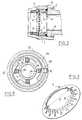
- connection deviceintended to ensure the connection between a section of pipe T and a connection piece E belonging to an apparatus or to a functional member installed in line on the pipe .
- This connection deviceis essentially constituted by a tubular sleeve 1 divided into two axially successive parts 2 and 3, the part 2 being fitted internally with components to produce an instant connection, the part 3 being intended to cover, in a removable manner, the end piece E of the device or of the member to be connected to the pipe section T.
- these instant connection meansconsist of a metal washer 4, of frustoconical shape and having teeth 5 on the side of its inner circumference to bite the outer surface of the tube section T and prevent its removal when that -this is introduced into zone 2 of the sleeve 1.
- the washer 4is elastically deformable between a position shown in which the inside diameter of the washer 4 defined by the ends of the teeth 5, is greater than the outside diameter of the section T and a position in which the washer 4 is compressed between two radial surfaces 6, 7, the effect of which is to modify the angle of the truncated cone and thus to place the ends of the teeth 5 on a circumference smaller than the circumference of the section T.
- the surface 6belongs to a ring 8 which rests on a shoulder 9 inside the part 2 of the sleeve 1 while the surface 7 belongs to a ring 10 which is axially movable inside this sleeve, the compression of the washer 4 being ensured by the action of the end piece E on the ring 10 when this end piece E is capped by the part 3 of the tubular sleeve 1.
- the end piece Eis here externally threaded and to cap this end piece E in a removable manner, the sleeve 1 has in its zone 3 an internal thread 11. It is therefore by screwing the sleeve 1 on the end piece E that is caused the crushing of the washer 4 between the two rings 8 and 10, thus arming the instant connection elements.
- the axial zone 2 of the sleeve 1has, beyond the shoulder 9, a lip seal 12 which seals between the sleeve 1 and the section T.
- the ring 10has a front seal 13 which seals between the sleeve 1 and the end piece E. The connection between the end piece E and the pipe T is therefore sealed.
- the front face 14 of the end piece Econstitutes a stop for the insertion into the sleeve 1 of the end of the section T when the end piece E is screwed into the zone 3 of the sleeve 1.
- each member or device to be connected to a section of pipe Tcan be pre-equipped with a sleeve 1 which is screwed onto the end piece E so that the instant connection elements that this sleeve comprises are reinforced as illustrated in FIG. 2
- the connection of an apparatus thus provided to a section T of pipeis carried out simply by fitting the section T into the sleeve 1, this fitting being stopped by the contact between the end face 15 of the section T and the front face 14. of the end piece E.
- the washer 4(see FIG. 3) at instead of being tapered , can be formed in a toric surface portion. In the free state, its inside diameter d is greater than that outside of the tube section T.
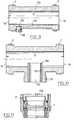
- FIG 4shows two alternative embodiments of a connection device according to the invention, one concerning the means associated with the second axial part of the sleeve 1 for sealingly and demountably fitting the connection end piece E, l other concerning the instant connection means housed in the first axial part of the sleeve 1.
- the screw coupling between the end piece E and the sleeve 1is replaced by a coupling collar 16, for example in two articulated half-parts, the closure of which straddles the sleeve 1 and the end piece E allows, thanks to the cooperation of conical surfaces 17, 18 provided respectively on the collar and on the outside of the end piece, to firmly hold the end piece E inside a cylindrical surface 19 of the second zone axial 3 of the sleeve 1, provided with a seal 20, against a shoulder 21 axially limiting this bearing 19.
- the instant connection meansuse a clamp 22 whose axial arms 23 are elastic and terminated by teeth 24.
- the tip of the teeth 24is, at rest, situated on a circumference of diameter larger than the outside diameter of the tube T.
- These teethcan be forced to penetrate into the tube T by means of a ring 25 which has cam surfaces 26 which form, when the the ring 25 is turned in the positive direction S in FIG.
- the control of the ring 25can be effected by means of an external annular control ring 27 which cooperates with at least one extension 28 of the ring 25 passing through the tubular wall sleeve 1.
- FIG. 6in a partial view, illustrates the constitution of a compressed fluid distribution network according to the invention.
- a functional element 125is constituted by a straight tap, externally threaded.
- the end piece E for connecting this functional elementis covered by a sleeve 1 according to the invention which comprises on the one hand a thread for screwing onto this end piece and on the other hand the instant connection means for receiving one end of the section T1 of pipeline.
- the connection of the section T1 with the successive section T2is ensured by means of a double union 126 which comprises at each of its ends connection ends on which the sleeves are pre-mounted 1.
- the networkcomprises, between a section Tn and a section Tn + 1, a functional element 127, for example a tap or a manual valve, connected to these sections by means of the connection device of the invention.
- FIGS. 7 and 8illustrate how, for example, it is easy to deposit a double union such as that 126 of FIG. 6. It suffices in fact to unscrew each of the sleeve 1 of the ends E of this double union and to slide these sleeves along the sections T1 and T2 to completely release, as shown in FIG. 8, the functional element 126. It is then possible to replace this double union by any functional element which will include, like the double union, in the same place , two end caps E on which the sleeves can be screwed on again. This screwing will at the same time cause, if these sleeves are of the type of embodiment illustrated in FIG. 1, the arming of the instant connection means of the sections T1 and T2.
- Figure 9is a longitudinal sectional view of a particular double union which has between the two ends E externally threaded, a drain port 128 located at the low point of a lower surface 129 of the double union forming double slope.
- This orificecan be closed by a plug 130 or by any closing device with manual or automatic control, allowing the draining of the pipe, that is to say the draining of the condensation water which it may contain.
- the internal diameter of this componentis of course equal to the internal diameter of the pipe sections which it connects to form a stop for mounting and so as not to create a pressure drop in the pipe.
- Figure 10illustrates in a longitudinal sectional view another functional member capable of being used in a network constructed in accordance with the invention. It is a connection T comprising between two end piece E a third end piece 131 which can have an external thread for its connection either to the device having a corresponding tapping and in this case it will be advantageous. that the external thread is standardized, that is to say determined by the nominal passage diameter of the orifice 132 which it surrounds, either to receive the threaded zone 3 of a sleeve 1 belonging to the connection device conforming to the invention. It will be noted that to avoid a descent of condensation water present in the horizontal sections of a distribution network in the vertical bypass which can be installed on these horizontal sections thanks to the functional T-shaped element of FIG.
- the orifice 132can, in a variant, be delimited in a threaded insert with a standardized diameter allowing any straight stitching to be implanted.
- one of the advantageous characteristics of the inventionresides in the fact that the end faces 114 of the opposite end pieces E of each functional member placed in a network, are spaced from each other by a distance Unique D for all the functional components whether these are union fittings, Tees, valves and taps, or any other device.
- FIG. 11illustrates the connection of a sleeve 1 according to the invention with a functional element which is reduced to a plug 135, that is to say a radial wall equipped with a cylindrical rim forming a threaded end piece E.
- the radial wallmay include means not shown for its actuation by screwing or unscrewing inside the sleeve 1.
- the functional elements according to the inventionare not limited to those illustrated above. They also include, for example, elements which have a connecting end piece E and at the other end a thread or a standard thread to allow the connection of a conventional component.
- the sleeve 1in its embodiment according to Figure 1, has a grooved outer surface which allows its manual operation.
- connection device of the inventionby the very fact that it is movable along the length of tube having been dissociated from the end piece of the device or from the member arranged in line between two sections, allows you to quickly modify the configuration of an existing network. It is in particular possible to design a network from a section of pipeline of determined lengths which constitutes the minimum pitch of the network, the location of each connection constituting the potential starting location for a diversion of the main line of the network. Likewise, each branch line can be made by butting sections of determined lengths also forming a step which determines the modularity of the branch line.
- connection according to the inventionmakes it possible to place on the market a minimum of elements, in the form of a kit, for the production of distribution networks for pressurized fluid inside a specific room .
- modulesthat would include a specific section of pipe provided at its two ends with the connection sleeve 1, the components of the instant connection being in their disarmed state.
- the marketing of the constituents of a distribution network according to the inventionwith two types of products: the bare sections constituting the first type while the functional members are pre-equipped with connection sleeves. tightened or coupled to their end pieces, the components of the instantaneous connection then being in their armed state.
Landscapes
- Engineering & Computer Science (AREA)
- General Engineering & Computer Science (AREA)
- Mechanical Engineering (AREA)
- Quick-Acting Or Multi-Walled Pipe Joints (AREA)
Abstract
Description
Translated fromFrenchLa présente invention concerne un dispositif de connexion entre un tronçon de canalisation et un composant fonctionnel ou de raccordement d'une installation de fluide sous pression, permettant la réalisation d'un réseau de distribution de fluide d'une manière simple, rapide, rationnelle et évolutive ou configurable en fonction de l'évolution des besoins de l'utilisateur.The present invention relates to a device for connecting between a pipe section and a functional or connection component of a pressurized fluid installation, allowing the creation of a fluid distribution network in a simple, rapid, rational and scalable or configurable according to the changing needs of the user.
La réalisation d'un réseau de distribution par exemple d'air comprimé dans une usine relève à l'heure actuelle, essentiellement de la plomberie, c'est-à-dire de la mise en place artisanale des canalisations formant ce réseau (découpe à longueur de tuyauteries, formage des tronçons sur le site en fonction des contraintes géométriques du lieu, brasage, soudage ou collage des éléments de raccordement ou de dérivation aux tronçons de tuyauterie). Dans certains cas, on utilise également des dispositifs d'accouplement de tronçons de tube par griffes comme illustrés par le document GB 2 117 072, qui permettent de gagner un peu de temps. La modification ou l'évolution d'une installation de ce type demande une reprise complète de celle-ci pour y insérer telle ou telle dérivation supplémentaire ou en supprimer telle autre. Même pour des évolutions mineures de l'installation telle par exemple que l'augmentation du diamètre d'une dérivation, par suite d'une demande accrue d'énergie sur cette ligne, il faut procéder à des aménagements lourds qui immobilisent longuement l'installation.The creation of a distribution network, for example of compressed air in a factory, is currently a matter mainly of plumbing, that is to say the artisanal installation of the pipes forming this network (cutting to length of piping, forming of sections on site according to the geometrical constraints of the place, brazing, welding or bonding of the elements of connection or bypass to the sections of piping). In certain cases, devices for coupling tube sections by claws are also used as illustrated by the
La présente invention entend remédier aux inconvénients des installations actuelles et de leur technique de pose en proposant principalement des moyens de connexion qui permettent un montage extrêmement rapide d'une installation nouvelle avec la possibilité de modifier aisément sa configuration, la nature ou l'emplacement des éléments fonctionnels qui la constituent.The present invention intends to remedy the drawbacks of current installations and their installation technique by mainly proposing connection means which allow extremely rapid assembly of a new installation with the possibility of easily modifying its configuration, the nature or the location of the functional elements that constitute it.
En effet, la nature même des moyens de connexion propres à l'invention permet de diviser la ou les canalisations qui composent l'installation ou le réseau en éléments ou tronçons modulaires qu'il est aisé de remplacer ou modifier, ces tronçons étant fournis dans une série de longueurs prédéterminées et ne comportant aucun moyen d'extrémité spécifique pour leur raccordement à l'installation. Les moyens de raccordement sont concentrés dans un élément spécifique s'interposant entre l'extrémité d'un tronçon et un organe fonctionnel, cet organe fonctionnel pouvant être réduit à une union ou un bouchon.Indeed, the very nature of the connection means specific to the invention makes it possible to divide the pipe or pipes which make up the installation or the network into modular elements or sections which it is easy to replace or modify, these sections being provided in a series of predetermined lengths and having no specific end means for their connection to the installation. The connection means are concentrated in a specific element interposed between the end of a section and a functional member, this functional member being able to be reduced to a union or a plug.
Plus précisément l'invention a pour objet une ligne de distribution de Fluide sans pression comprenant au moins un tronçon de canalisation et au moins un élément fonctionnel ou de raccordement avec un embout, la liaison de l'embout au tronçon étant assurée par un dispositif qui comporte un manchon tubulaire divisé en deux parties axialement successives, la première partie étant équipée intérieurement des composants d'un raccord à connexion instantanée pour l'extrémité du tronçon de canalisation, la seconde partie comportant des moyens pour coiffer de manière étanche et démontable l'embout de raccordement dont la face d'extrémité constitue, lorsque l'embout est coiffé du manchon, une butée axiale de l'extrémité du tronçon engagée dans la première partie du manchon. Ce manchon regroupant les moyens de connexion présente de nombreux avantages. Le premier est qu'il peut être pré-monté sur les embouts de raccordement d'un organe. Chaque organe ainsi équipé est donc à connexion instantanée pour les tronçons de canalisation qui l'encadrent. Le second avantage est tel qu'en "décoiffant" chaque embout, on peut désolidariser un organe des tronçons qui l'encadrent et retirer cet organe sans déplacer les tronçons qui portent chacun un manchon tubulaire en attente d'un autre organe à "recoiffer" dans la mesure où il est interchangeable avec l'organe déposé. On réalise ainsi ce qui sera appelé ci-après une connexion instantanée éclissée autorisant une première connexion bout à bout d'éléments formant une ligne avec déconnexions et connexions ultérieures perpendiculairement à la ligne.More precisely, the subject of the invention is a pressure-free fluid distribution line comprising at least one section of pipe and at least one functional element or of connection with a nozzle, the connection of the nozzle to the segment being ensured by a device which comprises a tubular sleeve divided into two axially successive parts, the first part being fitted internally with the components of an instant connection connector for the end of the pipe section, the second part comprising means for sealing and removable covering connection end piece, the end face of which constitutes, when the end piece is capped with the sleeve, an axial stop of the end of the section engaged in the first part of the sleeve. This sleeve grouping the connection means has many advantages. The first is that it can be pre-mounted on the connection ends of an organ. Each member thus equipped is therefore instantaneous connection for the pipe sections which surround it. The second advantage is such that by "disheveling" each end piece, it is possible to separate an organ from the sections which surround it and remove this organ without moving the sections which each carry a tubular sleeve awaiting another organ to "recoiff" insofar as it is interchangeable with the deposited member. This produces what will be called hereinafter an instantaneous spliced connection allowing a first end-to-end connection of elements forming a line with disconnections and subsequent connections perpendicular to the line.
De manière préférée, les moyens pour coiffer l'embout comportent un taraudage de la seconde partie du manchon pour coopérer avec un filetage extérieur de l'embout.Preferably, the means for covering the end piece include a tapping of the second part of the sleeve to cooperate with an external thread of the end piece.
On rappellera par ailleurs que les raccords dits à connexion instantanée sont connus depuis de nombreuses années. Ils consistent essentiellement, dans leur forme de réalisation les plus simples, en un élément tubulaire qui est rapporté par vissage dans l'orifice taraudé d'un organe tel qu'un distributeur, un vérin, une vanne.... et qui comporte, à l'intérieur, des moyens pour accueillir de manière étanche le tube et pour, une fois engagé, l'y retenir contre un effort tendant à l'en extraire. Ces moyens qui agrippent l'extrémité du tube à l'intérieur de cet élément tubulaire peuvent être de deux types. On citera la rondelle légèrement conique, pourvue de dents sur sa périphérie intérieure qui délimite un diamètre intérieur de passage inférieur au diamètre extérieur du tube de sorte que les dents viennent mordre sur ce tube. Le deuxième dispositif connu consiste en une sorte de douille tubulaire dont une extrémité est divisée en languettes longitudinales équipées à leur extrémité d'une dent tournée radialement vers l'intérieur, ces languettes coopérant avec une sorte de butée circonférentielle située à l'intérieur de l'embout tubulaire qui, lors d'un effort tendant à extraire le tube hors de cet élément tubulaire, contraint radialement les dents à mordre dans le tube. Dans ce deuxième type le passage libre entre les dents, la douille étant au repos, est également inférieur au diamètre extérieur du tube.It will also be recalled that the so-called instant connection fittings have been known for many years. They consist essentially, in their simplest embodiment, of a tubular element which is attached by screwing into the threaded orifice of a member such as a distributor, a jack, a valve, etc. and which comprises, inside, means for sealingly accommodating the tube and for, once engaged, retaining it there against an effort tending to extract it. These means which grip the end of the tube inside this tubular element can be of two types. Mention will be made of the slightly conical washer, provided with teeth on its internal periphery which delimits an internal diameter of passage smaller than the external diameter of the tube so that the teeth come to bite on this tube. The second known device consists of a kind of tubular bushing, one end of which is divided into longitudinal tongues fitted at their end with a tooth turned radially inwards, these tongues cooperating with a kind of circumferential stop located inside the 'tubular tip which, during a force tending to extract the tube out of this tubular element, radially forces the teeth to bite into the tube. In this second type, the free passage between the teeth, the sleeve being at rest, is also less than the outside diameter of the tube.
Ces dispositifs de connexion instantanée sont en général indémontables. Il est cependant apparu la nécessité de les rendre démontables, et ce de manière aussi rapide que possible, et pour cela on a créé des dispositifs plus complexes comportant des poussoirs tubulaires interposés entre les dents et le tube, permettant, en les déplaçant par rapport aux dents, le long du tube, d'écarter ces dents et de libérer le tube qui peut alors être extrait. L'action sur ces poussoirs est en général en sens contraire de la direction d'extraction du tube, si bien que la manipulation de ce type de raccords n'est pas toujours très aisée, notamment lorsque ceux-ci sont de petites dimensions.These instant connection devices are generally non-removable. It appeared however the need to make them removable, and this as quickly as possible, and for that we created more complex devices comprising tubular pushers interposed between the teeth and the tube, allowing, by moving them relative to the teeth, along the tube, spread these teeth and release the tube which can then be extracted. The action on these pushers is generally in the opposite direction to the direction of extraction of the tube, so that manipulation of this type of fittings is not always very easy, especially when these are small.
On s'est en outre rendu compte qu'il pouvait être utile que les dents ou les griffes du dispositif de retenue axiale du tube dans l'élément tubulaire de connexion soient portées au contact de ce tube seulement après l'introduction de ce dernier dans l'élément tubulaire. En effet, lorsque les dents définissent au repos un diamètre de passage inférieur au diamètre extérieur du tube, l'introduction du tube provoque une rayure de cette extrémité qui peut nuire à la qualité de l'étanchéité, si le joint d'étanchéité est situé au-delà de ces dents dans le sens d'introduction du tube. Il peut être avantageux et simple de justement conserver cette position du joint sans pour autant souffrir des rayures.It has also been realized that it could be useful for the teeth or the claws of the tube axial retaining device in the tubular connection element to be brought into contact with this tube only after the introduction of the latter into the tubular element. In fact, when the teeth define at rest a passage diameter smaller than the outside diameter of the tube, the introduction of the tube causes a scratch in this end which can affect the quality of the seal, if the seal is located beyond these teeth in the direction of insertion of the tube. It can be advantageous and simple to precisely maintain this position of the seal without suffering from scratches.
Pour obtenir ce résultat supplémentaire dans l'invention, on a créé dans la première partie du manchon tubulaire, formant le dispositif de connexion susdit, un raccord instantané dont les composants comprennent des dents de retenue de l'extrémité du tronçon engagé dans la première partie qui sont solidaires d'un support déformable entre un premier état "de repos" dans lequel les dents de retenue sont disposées totalement à l'extérieur d'une circonférence égale à celle extérieure du tube à retenir et un second état, "en service" dans lequel les dents de retenue s'étendent au moins partiellement à l'intérieur de cette circonférence, tandis que des moyens de déformation du support sont prévus pour le faire passer de son premier à son second état et pour le maintenir dans ce second état.To obtain this additional result in the invention, there was created in the first part of the tubular sleeve, forming the aforementioned connection device, an instantaneous connection, the components of which include teeth retaining the end of the section engaged in the first part. which are integral with a deformable support between a first "rest" state in which the retaining teeth are disposed completely outside of a circumference equal to that outside of the tube to be retained and a second state, "in use" wherein the retaining teeth extend at least partially inside this circumference, while means for deforming the support are provided to make it pass from its first to its second state and to maintain it in this second state.
On a ainsi réalisé un dispositif de retenue d'un tube qui peut être armé et désarmé et ce avant ou après l'introduction du tube dans l'embout de raccordement. Ainsi, selon les exigences, notamment en ce qui concerne l'étanchéité, de ce raccordement on peut armer le dispositif avant l'introduction du tube, celui-ci jouant alors le rôle d'un dispositif de connexion classique, ou introduire le tube puis armer le dispositif de sorte que les dents pénètrent dans la surface extérieure du tube après que celui-ci a été introduit, la déconnexion s'effectuant dans les deux cas en désarmant, c'est-à-dire en décontraignant l'organe support des dents de retenue pour que celles-ci, sous l'effet de la déformation élastique vers son état de repos du support de dents, se trouve placées à l'extérieur du tube, libérant ainsi ce dernier.There has thus been produced a device for retaining a tube which can be armed and disarmed, either before or after the introduction of the tube into the connection piece. Thus, according to the requirements, in particular as regards the sealing, of this connection, the device can be armed before the introduction of the tube, the latter then playing the role of a conventional connection device, or introduce the tube then arm the device so that the teeth penetrate the external surface of the tube after it has been inserted, the disconnection being effected in both cases by disarming, that is to say by de-stressing the support member of the retaining teeth so that these, under the effect of elastic deformation towards its resting state of the tooth support, is placed outside the tube, thereby releasing the latter.
Plusieurs modes de réalisation de ces moyens sont possibles. Dans un premier mode de réalisation, le support est constitué par une rondelle équipée de dents intérieures contenues dans une surface sensiblement tronconique dont la grande base est rattachée à une couronne extérieure continue, qui est contenue dans une surface différente d'un plan radial, les moyens de déformation du support comportant deux surfaces radiales de pincement d'au moins la couronne extérieure de la rondelle, mobiles l'une par rapport à l'autre dans le sens axial à l'intérieur de l'embout, qui sont respectivement portées par un épaulement radial de la première partie du manchon tubulaire et par la face radiale d'une bague entretoise dont l'autre face est en appui sur la face d'extrémité de l'embout de raccordement.Several embodiments of these means are possible. In a first embodiment, the support is constituted by a washer fitted with internal teeth contained in a substantially frustoconical surface whose large base is attached to a continuous external crown, which is contained in a surface different from a radial plane, the deformation means of the support comprising two radial gripping surfaces of at least the outer ring of the washer, movable relative to each other in the axial direction inside the end piece, which are respectively carried by a radial shoulder of the first part of the tubular sleeve and via the radial face of a spacer ring, the other face of which bears on the end face of the connection end piece.
C'est ainsi, en vissant ou dévissant, ou plus précisément en bloquant ou débloquant le manchon sur l'embout que l'on arme et désarme l'élément actif de la connexion instantanée.It is thus, by screwing or unscrewing, or more precisely by blocking or unblocking the sleeve on the endpiece that the active element of the instant connection is armed and disarmed.
Dans un autre mode de réalisation, le support est en forme de pince dont les bras sont orientés sensiblement axialement, les extrémités libres de ces bras formant les dents de retenue du tube, les moyens de déformation de la pince comprenant alors des surfaces de came coopérant avec la partie extérieure des dents pour les faire passer du premier au second état et les libérer pour qu'elles passent du fait de leur élasticité propre, du second état où les dents sont actives au premier état où elles sont inactives.In another embodiment, the support is in the form of a clamp whose arms are oriented substantially axially, the free ends of these arms forming the retaining teeth of the tube, the means of deformation of the clamp then comprising cooperating cam surfaces with the outer part of the teeth to make them pass from the first to the second state and release them so that they pass because of their own elasticity, from the second state where the teeth are active to the first state where they are inactive.
Les surfaces de came peuvent être commandées manuellement, soit par rotation d'une bague qui permet l'enfoncement des dents dans le tube soit par une poussée axiale d'une bague à surface conique qui également conduit à un enfoncement de ces dents.The cam surfaces can be controlled manually, either by rotation of a ring which allows the teeth to be inserted into the tube, or by an axial thrust of a ring with a conical surface which also leads to a depression of these teeth.
D'autres caractéristiques et avantages de l'invention ressortiront des exemples de réalisation décrits ci-après.Other characteristics and advantages of the invention will emerge from the exemplary embodiments described below.
Il sera fait référence aux dessins annexés parmi lesquels :
- la figure 1 est une vue en coupe axiale du dispositif de connexion de l'invention, avec les moyens de connexion instantanée dans leur état désarmé,
- la figure 2 est une vue en coupe axiale d'une variante de la figure 1, la connexion instantanée étant armée,
- la figure 3 est une vue en perspective d'une rondelle conforme à l'invention permettant d'être placée dans un état armé par rapport à un état de repos où elle est inactive,
- les figures 4 et 5 sont des vues en coupe orthogonale d'un second mode de réalisation de l'invention,
- la figure 6 illustre la réalisation d'une partie de réseau conforme à l'invention,
- les figures 7 et 8 représentent le démontage d'un organe fonctionnel,
- la figure 9 est une vue en coupe axiale d'un raccord union double avec purge d'eau conforme à l'invention,
- la figure 10 est une vue en coupe d'un organe fonctionnel de dérivation,
- la figure 11 est une vue d'un élément d'extrémité d'une ligne du réseau.
- FIG. 1 is a view in axial section of the connection device of the invention, with the instant connection means in their disarmed state,
- FIG. 2 is a view in axial section of a variant of FIG. 1, the instant connection being armed,
- FIG. 3 is a perspective view of a washer according to the invention making it possible to be placed in an armed state with respect to a state of rest where it is inactive,
- FIGS. 4 and 5 are views in orthogonal section of a second embodiment of the invention,
- FIG. 6 illustrates the construction of a network part in accordance with the invention,
- FIGS. 7 and 8 represent the disassembly of a functional member,
- FIG. 9 is a view in axial section of a double union connection with water purge according to the invention,
- FIG. 10 is a sectional view of a functional bypass member,
- Figure 11 is a view of an end element of a network line.
A la figure 1 on a représenté un premier mode de réalisation d'un dispositif de connexion destiné à assurer la liaison entre un tronçon de canalisation T et un embout de raccordement E appartenant à un appareil ou à un organe fonctionnel installé en ligne sur la canalisation. Ce dispositif de connexion est essentiellement constitué par un manchon tubulaire 1 divisé en deux parties axialement successives 2 et 3, la partie 2 étant équipée intérieurement de composants pour réaliser un raccord à connexion instantanée, la partie 3 étant destinée à coiffer, de manière démontable, l'embout E de l'appareil ou de l'organe à raccorder au tronçon T de canalisation.In Figure 1 there is shown a first embodiment of a connection device intended to ensure the connection between a section of pipe T and a connection piece E belonging to an apparatus or to a functional member installed in line on the pipe . This connection device is essentially constituted by a
Dans la cas de la figure 1, ces moyens de connexion instantanée consistent en une rondelle 4 métallique, de forme tronconique et possédant du côté de sa circonférence intérieure des dents 5 pour mordre la surface extérieure du tronçon de tube T et empêcher son retrait lorsque celui-ci est introduit dans la zone 2 du manchon 1. La rondelle 4 est élastiquement déformable entre une position représentée dans laquelle le diamètre intérieur de la rondelle 4 défini par les extrémités des dents 5, est supérieur au diamètre extérieur du tronçon T et une position dans laquelle la rondelle 4 est comprimée entre deux surfaces radiales 6, 7, dont l'effet est de modifier l'angle du tronc de cône et ainsi de placer les extrémités des dents 5 sur une circonférence plus petite que la circonférence du tronçon T.In the case of FIG. 1, these instant connection means consist of a
La surface 6 appartient à une bague 8 qui prend appui sur un épaulement 9 intérieur de la partie 2 du manchon 1 tandis que la surface 7 appartient à une bague 10 qui est mobile axialement à l'intérieur de ce manchon, la compression de la rondelle 4 étant assurée par l'action de l'embout E sur la bague 10 lorsque cet embout E est coiffé par la partie 3 du manchon tubulaire 1.The
L'embout E est ici fileté extérieurement et pour coiffer cet embout E de manière démontable, le manchon 1 comporte dans sa zone 3 un taraudage intérieur 11. C'est donc en vissant le manchon 1 sur l'embout E que l'on provoque l'écrasement de la rondelle 4 entre les deux bagues 8 et 10, armant ainsi les éléments de connexion instantanée.The end piece E is here externally threaded and to cap this end piece E in a removable manner, the
La zone axiale 2 du manchon 1 possède, au-delà de l'épaulement 9, un joint 12 d'étanchéité à lèvre qui assure l'étanchéité entre le manchon 1 et le tronçon T. La bague 10 possède quant à elle un joint frontal 13 qui assure l'étanchéité entre le manchon 1 et l'embout E. La liaison entre l'embout E et la canalisation T est donc rendue étanche.The
Il faut noter que la face frontale 14 de l'embout E constitue une butée à l'enfoncement dans le manchon 1 de l'extrémité du tronçon T lorsque l'embout E est vissé dans la zone 3 du manchon 1. On comprend que chaque organe ou appareil à raccorder à un tronçon de canalisation T, peut être pré-équipé d'un manchon 1 qui est vissé sur l'embout E de sorte que les éléments de connexion instantanée que ce manchon comporte sont armés comme illustré par la figure 2. La connexion d'un appareil ainsi pourvu à un tronçon T de canalisation est réalisée simplement en emboîtant le tronçon T dans le manchon 1, cet emboîtement étant arrêté par le contact entre la face d'extrémité 15 du tronçon T et la face frontale 14 de l'embout E. La forme de réalisation de certains des éléments de la figure 2, diffère un peu de celle des éléments portant les mêmes références représentés à la figure 1. C'est ainsi que la rondelle 4 (voir figure 3) au lieu d'être tronconique, peut être formée dans une portion de surface torique. A l'état libre son diamètre intérieurd est supérieur à celui extérieur du tronçon de tube T.It should be noted that the
Ce n'est pas sortir du cadre de l'invention que de prévoir à la place d'une liaison filetée entre la zone 3 du manchon 1 et l'embout E, une autre liaison par exemple par emmanchement, qui serait maintenue au moyen d'un bridage extérieur entre des collerettes que comporterait en correspondance l'embout E et le manchon 1 (voir figure 4).It is not outside the scope of the invention to provide, in place of a threaded connection between
Pour démonter la connexion réalisée avec le dispositif de la figure 1, il suffit de dévisser le manchon pour le déconnecter de l'embout E. Ce dévissage donne de plus en plus de jeu à l'empilement serré 8, 4, 10 et la rondelle 4 à dents 5 peut ainsi retrouver sa forme initiale dans laquelle l'extrémité des dents 5 se trouve à l'extérieur du tronçon de tube T. Il est alors possible de faire coulisser le manchon 1 sur le tube T sans le rayer.To dismantle the connection made with the device of FIG. 1, it suffices to unscrew the sleeve to disconnect it from the end piece E. This unscrewing gives more and more play to the
A la figure 4, on retrouve la plupart des éléments déjà décrits avec les mêmes références. Cette figure fait apparaître deux variantes de réalisation d'un dispositif de connexion conforme à l'invention, l'une concernant les moyens associés à la seconde partie axiale du manchon 1 pour coiffer de manière étanche et démontable l'embout E de raccordement, l'autre concernant les moyens de connexion instantanée logés dans la première partie axiale du manchon 1.In Figure 4, we find most of the elements already described with the same references. This figure shows two alternative embodiments of a connection device according to the invention, one concerning the means associated with the second axial part of the
Ainsi, à cette figure, l'accouplement vissé entre l'embout E et le manchon 1 est remplacé par un collier d'attelage 16, par exemple en deux demi-parties articulées, dont la fermeture à cheval sur le manchon 1 et l'embout E permet, grâce à la coopération de surfaces coniques 17, 18 prévues respectivement sur le collier et à l'extérieur de l'embout, de maintenir fermement l'embout E à l'intérieur d'une portée cylindrique 19 de la seconde zone axiale 3 du manchon 1, pourvu d'un joint d'étanchéité 20, contre un épaulement 21 limitant axialement cette portée 19.Thus, in this figure, the screw coupling between the end piece E and the
Les moyens de connexion instantanée mettent en oeuvre une pince 22 dont les bras axiaux 23 sont élastiques et terminés par des dents 24. La pointe des dents 24 est, au repos, située sur une circonférence de diamètre plus important que le diamètre extérieur du tube T. Ces dents peuvent être contraintes à pénétrer dans le tube T par le biais d'une bague 25 qui possède des surfaces de came 26 qui forment, lorsque l'on tourne la bague 25 dans le sens S positif sur la figure 5, un coin entre le manchon tubulaire 1 et les bras 23, ce coin forçant la pénétration de la dent 24 correspondante dans le tube T si celui-ci déjà en place dans l'embout, ou plaçant les dents 24 sur une circonférence de diamètre plus petit que celui extérieur du tube T, si bien que lorsqu'on enfile ce dernier dans le dispositif armé de la sorte, il force son passage entre les dents 24 qui peuvent se déformer élastiquement et s'arc-boutent sur la surface extérieure du tube T. La commande de la bague 25 peut s'opérer au moyen d'une bague de commande annulaire extérieure 27 qui coopère avec au moins une extension 28 de la bague 25 traversant la paroi tubulaire du manchon 1.The instant connection means use a
Par une rotation inverse de la bague 27 on relâche la pression des cames 26 sur les bras 23 qui, par leur élasticité propre, retrouvent leur position de repos libérant ainsi le tube T. On comprend que si l'on introduit le tube T avant d'avoir armé la pince 22, on évite de rayer la partie d'extrémité de ce tube qui doit coopérer avec le joint d'étanchéité 29. On garantit par là même une meilleure qualité à cette étanchéité 29.By a reverse rotation of the
D'autres variantes de réalisation peuvent être conçues sans sortir du cadre de l'invention. C'est ainsi que l'on peut imaginer la commande par l'intermédiaire d'un poussoir extérieur qui se visserait sur l'embout tubulaire 2 pour une surface de came conique venant coopérer sur l'arrière des bras de pince 23 pour agripper le tube, le dévissage de cette bague libérant ces bras pour leur permettre de retrouver leur état de repos. une rondelle 4 classique c'est-à-dire dont les dents 5 à l'état de repos peuvent mordre sur la surface extérieure du tronçon de tube T, ces dents pouvant être écartées par un dispositif de poussoir connu en lui-même. Dans ces conditions, le manchon, découplé de l'embout, peut également coulisser sur le tronçon T.Other alternative embodiments can be designed without departing from the scope of the invention. This is how one can imagine the control by means of an external pusher which would be screwed on the
La figure 6, par une vue partielle, illustre la constitution d'un réseau de distribution de fluide comprimé conformément à l'invention. C'est ainsi que sur la gauche de la figure, un élément fonctionnel 125 est constitué par un piquage droit, fileté extérieurement. L'embout E de raccordement de cet élément fonctionnel est recouvert par un manchon 1 conforme à l'invention qui comporte d'une part un filetage pour se visser sur cet embout et d'autre les moyens de connexion instantanée pour recevoir une extrémité du tronçon T1 de canalisation. Le raccordement du tronçon T1 avec le tronçon successif T2 est assuré au moyen d'une union double 126 qui comporte à chacune de ses extrémités des embouts de raccordement sur lesquels sont pré-montés les manchons 1. La mise en place de cette union 126 est réalisée simplement en l'enfilant sur l'extrémité libre du tronçon T1 puis en enfilant l'extrémité du tronçon T2 dans le manchon coiffant son autre extrémité. De la même manière, le réseau comporte entre un tronçon Tn et un tronçon Tn+1, un élément fonctionnel 127 par exemple un robinet ou une vanne manuelle, raccordés à ces tronçons au moyen du dispositif de connexion de l'invention.Figure 6, in a partial view, illustrates the constitution of a compressed fluid distribution network according to the invention. Thus on the left of the figure, a
Les figures 7 et 8 illustrent comment, par exemple, il est aisé de déposer une union double telle que celle 126 de la figure 6. Il suffit en effet de dévisser chacun des manchon 1 des embouts E de cette union double et de faire coulisser ces manchons le long des tronçons T1 et T2 pour dégager complètement comme le montre la figure 8, l'élément fonctionnel 126. Il est alors possible de remplacer cette union double par tout élément fonctionnel qui comportera, comme l'union double, à la même place, deux embouts E sur lesquels on pourra venir revisser les manchons 1. Ce vissage provoquera en même temps, si ces manchons sont du type de réalisation illustré par la figure 1, l'armement des moyens de connexion instantanée des tronçons T1 et T2.FIGS. 7 and 8 illustrate how, for example, it is easy to deposit a double union such as that 126 of FIG. 6. It suffices in fact to unscrew each of the
La figure 9 est une vue en coupe longitudinale d'une union double particulière qui possède entre les deux embouts E filetés extérieurement, un orifice 128 de purge situé au point bas d'une surface inférieure 129 de l'union double formant double pente. Cet orifice peut être fermé par un bouchon 130 ou par tout dispositif d'obturation à commande manuelle ou automatique, permettant la vidange de la canalisation, c'est-à-dire la purge de l'eau de condensation qu'elle peut contenir. Le diamètre intérieur de ce composant est bien entendu égal au diamètre intérieur des tronçons de canalisation qu'il relie pour en constituer une butée au montage et pour ne pas créer de perte de charge dans la canalisation.Figure 9 is a longitudinal sectional view of a particular double union which has between the two ends E externally threaded, a
La figure 10 illustre par une vue en coupe longitudinale un autre organe fonctionnel susceptible d'être utilisé dans un réseau construit conformément à l'invention. Il s'agit d'un T de raccordement comportant entre deux embout E un troisième embout 131 qui peut présenter un filetage extérieur pour son raccordement soit à l'appareil possédant un taraudage correspondant et dans ce cas il sera avantageux que le filetage extérieur soit normalisé, c'est-à-dire déterminé par le diamètre nominal de passage de l'orifice 132 qu'il entoure, soit pour recevoir la zone filetée 3 d'un manchon 1 appartenant au dispositif de connexion conforme à l'invention. On notera que pour éviter une descente d'eau de condensation présente dans les tronçons horizontaux d'un réseau de distribution dans la dérivation verticale qui peut être implantée sur ces tronçons horizontaux grâce à l'élément fonctionnel en T de la figure 10, on aura prévu que l'orifice 132 débouche dans le conduit principal du Té reliant les deux embout E au-dessus de la surface inférieure de ce conduit principal. Ce résultat peut être obtenu par tout moyen et notamment par la mise en place d'un insert 133 en forme de douille dont l'extrémité 134 intérieure au Té pénètre suffisamment pour toujours être située au-dessus du niveau d'eau pouvant stagner dans la canalisation horizontale supérieure du réseau de distribution.Figure 10 illustrates in a longitudinal sectional view another functional member capable of being used in a network constructed in accordance with the invention. It is a connection T comprising between two end piece E a
L'orifice 132 peut, dans une variante, être délimité dans un insert taraudé à un diamètre normalisé permettant d'implanter n'importe quel piquage droit.The
On remarquera que l'une des caractéristiques intéressantes de l'invention réside dans le fait que les faces terminales 114 des embouts opposés E de chaque organe fonctionnel mises en place dans un réseau, sont écartées l'une de l'autre d'une distance D unique pour tous les composants fonctionnels que ceux-ci soient des raccords-unions, des Tés, des vannes et robinets, ou tout autre dispositif.It will be noted that one of the advantageous characteristics of the invention resides in the fact that the end faces 114 of the opposite end pieces E of each functional member placed in a network, are spaced from each other by a distance Unique D for all the functional components whether these are union fittings, Tees, valves and taps, or any other device.
La figure 11 illustre la liaison d'un manchon 1 conforme à l'invention avec un élément fonctionnel qui se réduit à un bouchon 135, c'est-à-dire une paroi radiale équipée d'un rebord cylindrique formant embout fileté E. La paroi radiale peut comporter des moyens non représentés pour son actionnement en vissage ou dévissage à l'intérieur du manchon 1.FIG. 11 illustrates the connection of a
Les éléments fonctionnels conformes à l'invention ne sont pas limités à ceux illustrés ci-dessus. Ils comprennent aussi par exemple des éléments qui possèdent un embout E de raccordement et à l'autre extrémité un filetage ou un taraudage normalisé pour permettre la connexion d'un composant classique.The functional elements according to the invention are not limited to those illustrated above. They also include, for example, elements which have a connecting end piece E and at the other end a thread or a standard thread to allow the connection of a conventional component.
On notera que le manchon 1, dans sa réalisation conforme à la figure 1, possède une surface extérieure cannelée qui permet sa manoeuvre manuelle.Note that the
On comprend de ce qui précède que le dispositif de connexion de l'invention, du fait même qu'il est déplaçable le long du tronçon de tube en ayant été dissocié de l'embout de l'appareil ou de l'organe disposé en ligne entre deux tronçons, permet de modifier rapidement la configuration d'un réseau existant. Il est notamment possible de concevoir un réseau à partir de tronçon de canalisation de longueurs déterminées qui constitue le pas minimum du réseau, l'endroit de chaque connexion constituant l'endroit de départ potentiel d'une dérivation de la ligne principale du réseau. De même, chaque ligne de dérivation peut être réalisée par aboutage de tronçons de longueurs déterminées formant également un pas qui détermine la modularité de la ligne de dérivation.It is understood from the above that the connection device of the invention, by the very fact that it is movable along the length of tube having been dissociated from the end piece of the device or from the member arranged in line between two sections, allows you to quickly modify the configuration of an existing network. It is in particular possible to design a network from a section of pipeline of determined lengths which constitutes the minimum pitch of the network, the location of each connection constituting the potential starting location for a diversion of the main line of the network. Likewise, each branch line can be made by butting sections of determined lengths also forming a step which determines the modularity of the branch line.
On comprend également que la conception de la connexion selon l'invention permet de mettre sur le marché un minimum d'éléments, sous forme de kit, pour la réalisation de réseaux de distribution de fluide sous pression à l'intérieur d'un local déterminé. On peut même imaginer la vente de modules qui comprendraient un tronçon déterminé de canalisation pourvu à ses deux extrémités du manchon 1 de raccordement, les composants de la connexion instantanée étant dans leur état désarmé. A l'inverse, on peut concevoir la commercialisation des constituants d'un réseau de distribution selon l'invention avec deux types de produits : les tronçons nus constituant le premier type tandis que les organes fonctionnels sont pré-équipés des manchons de connexion serrés ou attelés à leurs embouts, les composants de la connexion instantanée étant alors dans leur état armé.It is also understood that the design of the connection according to the invention makes it possible to place on the market a minimum of elements, in the form of a kit, for the production of distribution networks for pressurized fluid inside a specific room . One can even imagine the sale of modules that would include a specific section of pipe provided at its two ends with the
Claims (13)
- A distribution line for fluid under pressure, including at least a length (T) of duct and at least a functional (127) or a length coupling (126) member, characterized in that each functional (127) or coupling (126) member includes at least an endpiece (E), and in that its connection to the length (T) is performed by means of a device including a tubular sleeve (1) comprising two portions (2, 3) in axial succession, the first portion (2) being fitted on its inside with components (4, 12) of an instant connection coupling for the end of the length (T) of duct, the second portion (3) including means (11, 16, 19) for releasably and sealably covering the coupling endpiece (E), and in that the end face (14) of the endpiece (E) constitutes an axial abutment for the end of the length (T) engaged in the first portion (2) of the sleeve, when the endpiece is covered by the sleeve (1).
- A distribution line according to claim 1, characterized in that the means for covering the endpiece include tapping (11) in the second portion (3) of the sleeve to co-operate with an outside thread on the endpiece (E).
- A distribution line according to claim 1, characterized in that the instant connection coupling components comprise teeth (5, 24) for retaining the end of the length (T) engaged in the first portion (2) and secured to a support (4, 23) which is deformable between a "rest", first state in which the retaining teeth are disposed completely outside a circumference of diameter equal to the outside diameter of the tube (T) to be retained, and a "in-use", second state in which the retaining teeth (5, 24) extend at least partially into said circumference, while means (8, 10, 25, 26) are provided for deforming the support (4, 23) to cause it to pass from its first state to its second state, and to hold it in said second state.
- A distribution line according to claim 3, characterized in that the support is constituted by a washer (4) fitted with inside teeth (5) contained in a surface that is substantially frustoconical, the bases of the teeth being attached to a continuous outer ring which lies in a surface other than a radial plane, the means for deforming the support including two radial clamping surfaces for clamping at least the outer ring of the washer (4) and movable relative to each other in an axial direction inside the sleeve (1).
- A distribution line according to claim 2 and claim 4, characterized in that one of the radial clamping surfaces is formed by a radial shoulder (9) on the first portion, the other being constituted by a radial face on a spacer ring (10) having its other radial face bearing against the end face (14) of the coupling endpiece.
- A distribution line according to claim 5, characterized in that it includes another spacer ring (8) between the peripheral portion of the washer (4) and the inside shoulder (9) of the first portion.
- A distribution line according to claim 4, characterized in that the outer ring of the washer is in the form of a portion of a torus.
- A distribution line according to claim 3, characterized in that the support is in the form of a clamp (22) whose arms (23) extend substantially axially, the free ends of the arms (23) forming the tube-retaining teeth (24), the means for deforming the clamp (22) comprising camming surfaces (26) that co-operate with the outside portion of the arms (23) to cause them to move the teeth from their first state towards their second state.
- A distribution line according to claim 1, characterized in that the coupling element (126) for lengths of duct includes a tubular element whose inside diameter is equal to the inside diameter of the lengths to be connected, the ends of said element being of sufficient thickness to form an endpiece (E) having an outside thread and a nominal diameter greater than the outside diameter of the lengths (T) to be connected.
- A distribution line according to claim 9, characterized in that the coupling element (126) for length of duct includes an inclined surface (129) on its inside face, said surface being inclined relative to the axis so as to terminate at a bleed orifice (128) formed radially through the wall and fitted with a removable plug (130).
- A distribution line according to claim 1, characterized in that the functional element (127) is of valve or faucet type and includes two endpieces (E) for connection to respective lengths of duct, having an inside diameter equal to the inside diameter of the lengths to be connected and of sufficient thickness to possess an outside thread having a nominal diameter greater than the outside diameter of the lengths to be connected.
- A distribution line according to claim 1, characterized in that the functional element is of the T-branch type and includes two endpieces (E) for connection to respective lengths of duct, its inside diameter being equal to the inside diameter of the lengths to be connected and its thickness being sufficient to possess an outside thread having a nominal diameter greater than the outside diameter of the lengths to be connected, and also having a branch orifice (132) between the two endpieces (E), which branch orifice is tapped and/or threaded (131) to a standardized diameter.
- A distribution line according to any one of the claims 9 to 12, characterized in that the functional element (127) or the coupling element (26) includes two opposite endpieces (E) in line, having end faces (14) that are spaced apart by the distance (D) regardless of the type of element.
Applications Claiming Priority (4)
| Application Number | Priority Date | Filing Date | Title |
|---|---|---|---|
| FR9116173AFR2685754A1 (en) | 1991-12-26 | 1991-12-26 | Connection device for components of a fluid-distribution network (main), network and components applying it |
| FR9116173 | 1991-12-26 | ||
| FR9116174 | 1991-12-26 | ||
| FR9116174AFR2685755A1 (en) | 1991-12-26 | 1991-12-26 | Connection device for the quick coupling of the end of a tube to a member |
Publications (2)
| Publication Number | Publication Date |
|---|---|
| EP0550323A1 EP0550323A1 (en) | 1993-07-07 |
| EP0550323B1true EP0550323B1 (en) | 1996-08-14 |
Family
ID=26229147
Family Applications (1)
| Application Number | Title | Priority Date | Filing Date |
|---|---|---|---|
| EP92403499AExpired - LifetimeEP0550323B1 (en) | 1991-12-26 | 1992-12-21 | Connector device for parts of fluid distribution artwork, said parts and said network |
Country Status (6)
| Country | Link |
|---|---|
| US (1) | US5553901A (en) |
| EP (1) | EP0550323B1 (en) |
| JP (1) | JP2795786B2 (en) |
| AT (1) | ATE141395T1 (en) |
| DE (1) | DE69212793T2 (en) |
| ES (1) | ES2092076T3 (en) |
Families Citing this family (62)
| Publication number | Priority date | Publication date | Assignee | Title |
|---|---|---|---|---|
| GB9512513D0 (en)* | 1995-06-20 | 1995-08-23 | Guest John D | Improvements in or relating to T-connectors |
| US5695224A (en)* | 1995-08-14 | 1997-12-09 | The Rovac Corporation | Pipe joint assembly |
| GB9516697D0 (en)* | 1995-08-15 | 1995-10-18 | Opella Ltd | Tube coupling |
| FR2740531B1 (en)* | 1995-10-27 | 1997-11-21 | Legris Sa | IMPROVEMENT TO A DEVICE FOR CONNECTING A TUBE TO A TIP |
| FR2758379B1 (en)* | 1997-01-14 | 1999-02-19 | Parker Hannifin Rak Sa | IMPLEMENTATION CARTRIDGE FOR A PIPE CONNECTION FOR TAKING PLACE IN A HOUSING |
| US5890830A (en)* | 1997-09-04 | 1999-04-06 | Pentech International Inc. | Universal marking instrument apparatus |
| JP3076981B2 (en)* | 1997-11-10 | 2000-08-14 | 株式会社ソーラー技研 | Pipe fittings |
| MXPA01006008A (en)* | 1998-12-18 | 2003-06-09 | Accor Technology Inc | Tube coupling. |
| FR2788832B1 (en)* | 1999-01-26 | 2001-02-23 | Legris Sa | DEVICE FOR QUICK CONNECTION OF A TUBE TO A RIGID ELEMENT |
| FR2792702B1 (en)* | 1999-04-21 | 2001-05-18 | Legris Sa | QUICK CONNECTION DEVICE |
| WO2001018440A2 (en)* | 1999-09-09 | 2001-03-15 | R. Conrader Company | Tube fitting |
| US6663145B1 (en)* | 2000-11-06 | 2003-12-16 | Group Timberline, Inc. | Conduit coupling with interior grip rings |
| PT1446605E (en)* | 2001-11-23 | 2008-12-12 | Georg Fischer Haustechnik Ag | Quick-release coupling for pipes |
| US6857670B2 (en) | 2001-12-05 | 2005-02-22 | Cuno Incorporated | Plastic tube joint |
| US7156423B2 (en)* | 2003-04-11 | 2007-01-02 | 3M Innovative Properties Company | Plastic tube joint |
| JP2005172218A (en)* | 2003-11-21 | 2005-06-30 | Hama International:Kk | Pipe fitting |
| USD550333S1 (en) | 2004-01-19 | 2007-09-04 | Georg Fischer Haustechnik Ag | Adapter |
| FR2866095B1 (en)* | 2004-02-05 | 2007-09-28 | Legris Sa | WASHER FOR TUBE CONNECTING DEVICE, WASHER PRODUCING METHOD, AND CONNECTING DEVICE |
| DE102005055382A1 (en)* | 2005-11-17 | 2007-05-24 | Peter Ilesic | Clamping ring of a tensionable pipe coupling |
| JP2007170501A (en)* | 2005-12-20 | 2007-07-05 | Inax Corp | Piping joint |
| FR2896572B1 (en)* | 2006-01-23 | 2009-07-03 | Saint Gobain Pam Sa | TUBULAR JUNCTION |
| US7832773B2 (en)* | 2006-09-18 | 2010-11-16 | Krohn Kenneth P | Adjustable connector and method for its use |
| US8109539B2 (en)* | 2007-07-17 | 2012-02-07 | Krohn Kenneth P | Variable joining device and method for its use |
| US7530606B1 (en)* | 2008-01-04 | 2009-05-12 | Richard Yang | Quick pipe connector |
| US20090208271A1 (en)* | 2008-02-19 | 2009-08-20 | Krohn Kenneth P | Modular coupling system |
| US20090218808A1 (en)* | 2008-03-01 | 2009-09-03 | Krohn Kenneth P | Improved duct coupling system |
| US20090230678A1 (en)* | 2008-03-14 | 2009-09-17 | Krohn Kenneth P | Compression fitting adjustment system |
| US20100019484A1 (en)* | 2008-07-23 | 2010-01-28 | Krohn Kenneth P | Compression fitting adjustment system |
| US20100133810A1 (en)* | 2008-11-29 | 2010-06-03 | Krohn Kenneth P | Device for connecting to ducts of various sizes and shapes |
| US8303001B2 (en)* | 2009-01-13 | 2012-11-06 | Kofulso Co., Ltd. | Pipe connector |
| US20100283237A1 (en)* | 2009-01-24 | 2010-11-11 | Krohn Kenneth P | Device for connecting to ducts of various sizes and shapes |
| AU2010206066A1 (en)* | 2009-08-03 | 2011-02-17 | Gsa Industries (Aust.) Pty. Ltd. | Pipe coupling |
| US8833733B2 (en) | 2010-01-21 | 2014-09-16 | Automatic Switch Company | Valve connections |
| US8454058B2 (en)* | 2010-08-09 | 2013-06-04 | GM Global Technology Operations LLC | High pressure fitting for hydrogen applications |
| CN102182889A (en)* | 2011-05-13 | 2011-09-14 | 房县启扬工贸有限责任公司 | Portable pipe joint |
| KR101110400B1 (en)* | 2011-09-30 | 2012-02-24 | 주식회사 우정메카트로닉스 | Pipe connector assembly and pipe connection method using the same |
| US8910980B2 (en) | 2011-11-08 | 2014-12-16 | Thomas & Betts International, Inc. | Liquid-tight fitting |
| US8657343B2 (en)* | 2012-02-06 | 2014-02-25 | Watts Water Technologies, Inc. | Quick connector assembly |
| US9739404B2 (en)* | 2013-04-24 | 2017-08-22 | Philadelphia Scientific Llc | Battery water replenishment system and method of installation |
| US20140318064A1 (en)* | 2013-04-25 | 2014-10-30 | Russell William Reinhardt | Press-on retainer for fire-stopping sleeve |
| US9447906B2 (en) | 2013-12-11 | 2016-09-20 | Nibco Inc. | Self-locking push-to-connect insert |
| US9541228B2 (en)* | 2013-12-11 | 2017-01-10 | Nibco Inc. | Push-to-connect fitting |
| US10006575B2 (en) | 2013-12-11 | 2018-06-26 | Nibco Inc. | Modular push-to-connect assembly |
| US9777875B2 (en) | 2014-02-26 | 2017-10-03 | Nibco Inc. | Clam shell push-to-connect assembly |
| US9810359B2 (en) | 2014-10-06 | 2017-11-07 | Spears Manufacturing Co. | Pipe coupling |
| JP2016089899A (en)* | 2014-10-31 | 2016-05-23 | 株式会社日本ピスコ | Pipe joint and manufacturing method of pipe joint |
| US9765912B2 (en) | 2014-11-06 | 2017-09-19 | Spears Manufacturing Co. | Telescoping pipe coupling |
| US9611970B2 (en)* | 2014-11-06 | 2017-04-04 | Spears Manufacturing Co. | Pipe cap |
| DE102015122766A1 (en)* | 2015-12-23 | 2017-08-03 | Voss Automotive Gmbh | "Toothed disc with multi-bar retaining teeth" |
| US11187362B2 (en)* | 2016-06-14 | 2021-11-30 | Acorn Engineering Company | Conduit connector assembly |
| CN106889743A (en)* | 2017-04-11 | 2017-06-27 | 洽兴包装工业(中国)有限公司 | The head construction of application device |
| US10920892B2 (en) | 2018-09-18 | 2021-02-16 | Accor Technology, Inc. | Adapter for connecting tubing with push-fit fittings |
| CA3115847A1 (en)* | 2018-10-09 | 2020-04-16 | Zhuji City Howhi Air Conditioners Made Co., Ltd. | Anti-dropping steel rng used in press-fitting type pipe fitting and fixing sealing device |
| JP7288659B2 (en)* | 2018-10-26 | 2023-06-08 | 光陽産業株式会社 | Joints for flexible pipes and fasteners for such joints |
| US10865923B2 (en) | 2018-11-19 | 2020-12-15 | Accor Technology, Inc. | Push-fit fitting and end bushing for use therewith |
| JP7209252B2 (en)* | 2018-11-30 | 2023-01-20 | パナソニックIpマネジメント株式会社 | joint |
| USD1033644S1 (en) | 2019-09-11 | 2024-07-02 | Medline Industries, Lp | Deformable medical compression device |
| US11510713B2 (en) | 2019-09-11 | 2022-11-29 | Medline Industries, Lp | Compression device, kit, and method |
| US20220341520A1 (en)* | 2021-04-21 | 2022-10-27 | Mueller International, Llc | Wide range pipe fitting |
| US12025255B2 (en) | 2021-04-23 | 2024-07-02 | Eaton Intelligent Power Limited | Quick action fluid coupler |
| US11974789B2 (en) | 2021-06-21 | 2024-05-07 | Medline Industries, Lp | Compression device, bone plate, bone plate assembly, kit, and method |
| US12313109B2 (en)* | 2022-07-21 | 2025-05-27 | Applied System Technologies, Inc. | End nut assembly |
Family Cites Families (29)
| Publication number | Priority date | Publication date | Assignee | Title |
|---|---|---|---|---|
| US425369A (en)* | 1890-04-08 | Hiram cowell | ||
| US1834102A (en)* | 1926-06-29 | 1931-12-01 | Roderick M Mccalley | Leakproof cover for bell and spigot pipe-joints |
| US2448888A (en)* | 1946-04-05 | 1948-09-07 | Chicago Forging & Mfg Co | Fitting |
| GB894671A (en)* | 1958-06-13 | 1962-04-26 | Chicago Forging & Mfg Co | Improvements in or relating to tube seals and the like |
| US3058762A (en)* | 1958-11-17 | 1962-10-16 | Earl E Howe | Screw thimble fitting having toggle rings with a sealing feature |
| FR1424837A (en)* | 1965-02-17 | 1966-01-14 | Seidl Karl | Crush seal |
| US3600010A (en)* | 1969-04-01 | 1971-08-17 | Williamson Inc T | Pipe coupling |
| US4000919A (en)* | 1969-04-09 | 1977-01-04 | Edwards Francis P | Pipe coupler |
| CH506743A (en)* | 1969-06-11 | 1971-04-30 | Schmid Kranz & Co Gmbh Zweigni | Pipe connection sleeve for the mechanically secured clamp fastening of smooth pipe ends - especially small-caliber steel pipes |
| US3711126A (en)* | 1969-11-24 | 1973-01-16 | Nippon Kokan Kk | Coupling for milli-wave guiding tube |
| US3669475A (en)* | 1970-05-22 | 1972-06-13 | Mueller Co | Compression couplings |
| US3633944A (en)* | 1970-11-23 | 1972-01-11 | Jacob J Hamburg | Tube coupling |
| JPS5151866Y2 (en)* | 1973-06-23 | 1976-12-11 | ||
| GB1520742A (en)* | 1975-07-30 | 1978-08-09 | Guest J D | Couplings for tubes |
| US4146254A (en)* | 1976-03-31 | 1979-03-27 | Bristol Products, Inc. | Coupler for tubing |
| US4072328A (en)* | 1976-05-25 | 1978-02-07 | Hepworth Plastics Limited | Pipe couplings |
| JPS55118077U (en)* | 1979-02-09 | 1980-08-20 | ||
| FR2468823A1 (en)* | 1979-10-30 | 1981-05-08 | Vallourec | JOINT FOR TUBES FOR THE PETROLEUM INDUSTRY |
| SE421238B (en)* | 1980-06-27 | 1981-12-07 | Gunnar Kemppainen | COUPLING |
| GB2117072A (en)* | 1982-03-12 | 1983-10-05 | Kelstan Plastic Prod | Tube coupling |
| US4635975A (en)* | 1985-09-25 | 1987-01-13 | Jaco Manufacturing Company | Quick-connect tube coupling |
| DD246030A1 (en)* | 1986-02-19 | 1987-05-27 | Medizin Labortechnik Veb K | LOOSABLE FUSE FOR CONNECTOR CONNECTIONS |
| AT387081B (en)* | 1986-05-15 | 1988-11-25 | Pickhard Ewald | CONNECTING DEVICE BETWEEN TUBULAR PIPES AND TO THIS CONNECTED TRANSITION PIECE |
| US4865359A (en)* | 1987-06-18 | 1989-09-12 | Brown & Root, Inc. | Press fit pipe joint and method |
| US4807911A (en)* | 1988-01-25 | 1989-02-28 | Short Charles D | Push in fitting converter for plastic tubing |
| DE3806404C2 (en)* | 1988-02-29 | 1994-06-09 | Raymond A Gmbh & Co Kg | Detachable connector for semi-rigid pipes |
| JPH01234686A (en)* | 1988-03-14 | 1989-09-19 | Junkosha Co Ltd | Pipe joint |
| DE4038539C1 (en)* | 1990-12-03 | 1992-04-30 | Parker-Ermeto Gmbh, 4800 Bielefeld, De | |
| US5160178A (en)* | 1991-12-17 | 1992-11-03 | Kabushiki Kaisha Com | Direct sealing coupling |
- 1992
- 1992-12-21EPEP92403499Apatent/EP0550323B1/ennot_activeExpired - Lifetime
- 1992-12-21ESES92403499Tpatent/ES2092076T3/ennot_activeExpired - Lifetime
- 1992-12-21ATAT92403499Tpatent/ATE141395T1/ennot_activeIP Right Cessation
- 1992-12-21DEDE69212793Tpatent/DE69212793T2/ennot_activeExpired - Fee Related
- 1992-12-28JPJP4349552Apatent/JP2795786B2/ennot_activeExpired - Lifetime
- 1994
- 1994-10-19USUS08/325,634patent/US5553901A/ennot_activeExpired - Lifetime
Also Published As
| Publication number | Publication date |
|---|---|
| JP2795786B2 (en) | 1998-09-10 |
| DE69212793T2 (en) | 1997-02-13 |
| EP0550323A1 (en) | 1993-07-07 |
| JPH0681989A (en) | 1994-03-22 |
| DE69212793D1 (en) | 1996-09-19 |
| ES2092076T3 (en) | 1996-11-16 |
| US5553901A (en) | 1996-09-10 |
| ATE141395T1 (en) | 1996-08-15 |
Similar Documents
| Publication | Publication Date | Title |
|---|---|---|
| EP0550323B1 (en) | Connector device for parts of fluid distribution artwork, said parts and said network | |
| EP0857274B1 (en) | Device for connecting a tube to a coupling | |
| FR2780483A1 (en) | CIRCUIT BREAKER FOR PRESSURE FLUID HANDLING INSTALLATION | |
| FR3117569A1 (en) | Device for aseptic connection of a tube | |
| EP1085245B1 (en) | Means for connecting a pipe to a tubular body | |
| CA2767635C (en) | Device for closing fuel-dump circuit of an aircraft | |
| EP0497647B1 (en) | Drain plug for hydraulic circuit | |
| FR2685754A1 (en) | Connection device for components of a fluid-distribution network (main), network and components applying it | |
| EP2548206B1 (en) | Blocking device for a fluid duct, e.g. for use in a nuclear power plant, in particular for blocking a steam generator bottom drain | |
| EP0034101B1 (en) | Disconnectable coupling, especially for joining two tubes or pipes | |
| FR2510228A1 (en) | SYSTEM FOR CONNECTING AUTOMATIC PIPE CONNECTIONS TO LIQUID OR GASEOUS FLUID DELIVERY DEVICES | |
| FR2473671A1 (en) | Demountable non-return valve - has threaded pipe connections each end and with double action seal one side of split housing | |
| FR2650051A1 (en) | CONNECTING END FOR PIPE OF SYNTHETIC MATERIAL AND MOUNTING METHOD | |
| BE880570A (en) | UNLOADING TAP FOR BOILERS AND SIMILAR PLANTS, COMPRISING A SPHERICAL SHUTTER | |
| FR1462277A (en) | Assembly for connection of washing machines for feeding and emptying | |
| FR2685755A1 (en) | Connection device for the quick coupling of the end of a tube to a member | |
| EP3867557B1 (en) | Assembly comprising a pipe and a connection device for tapping a tube on a wall of the pipe | |
| FR2625790A1 (en) | CONNECTING ELEMENT | |
| FR2703755A1 (en) | Device for connecting a flexible hose to a rigid end piece | |
| EP3059483B1 (en) | Connector for connecting pipes of an air-conditioning system and associated air-conditioning device | |
| FR2881203A1 (en) | Hydraulic treatment device for connecting e.g. building, to e.g. waterworks network, has retention unit disposed in air-gap to oppose itself to radial deformation of pipe under effect of tightening of paddle | |
| FR2744194A1 (en) | Drilling equipment fitting of branch pipe from water main with shut off cock | |
| FR2692335A1 (en) | Assembly and cutting tool for forming branch pipeline in situ - comprises upper tube with trepanning tool for removing disc from main pipe, fitted perpendicular to walls of main pipe and sealed by ring | |
| FR3108157A1 (en) | Support collar for plastic or rigid water pipes with tangential locking screws | |
| FR2571121A1 (en) | Branch connection sleeve for working on a synthetic material pipe under load |
Legal Events
| Date | Code | Title | Description |
|---|---|---|---|
| PUAI | Public reference made under article 153(3) epc to a published international application that has entered the european phase | Free format text:ORIGINAL CODE: 0009012 | |
| 17P | Request for examination filed | Effective date:19921222 | |
| AK | Designated contracting states | Kind code of ref document:A1 Designated state(s):AT BE CH DE ES FR GB IT LI LU NL SE | |
| 17Q | First examination report despatched | Effective date:19950309 | |
| GRAG | Despatch of communication of intention to grant | Free format text:ORIGINAL CODE: EPIDOS AGRA | |
| GRAH | Despatch of communication of intention to grant a patent | Free format text:ORIGINAL CODE: EPIDOS IGRA | |
| GRAH | Despatch of communication of intention to grant a patent | Free format text:ORIGINAL CODE: EPIDOS IGRA | |
| GRAA | (expected) grant | Free format text:ORIGINAL CODE: 0009210 | |
| AK | Designated contracting states | Kind code of ref document:B1 Designated state(s):AT BE CH DE ES FR GB IT LI LU NL SE | |
| REF | Corresponds to: | Ref document number:141395 Country of ref document:AT Date of ref document:19960815 Kind code of ref document:T | |
| REF | Corresponds to: | Ref document number:69212793 Country of ref document:DE Date of ref document:19960919 | |
| REG | Reference to a national code | Ref country code:CH Ref legal event code:NV Representative=s name:BOVARD AG PATENTANWAELTE | |
| GBT | Gb: translation of ep patent filed (gb section 77(6)(a)/1977) | Effective date:19960924 | |
| ITF | It: translation for a ep patent filed | ||
| REG | Reference to a national code | Ref country code:ES Ref legal event code:FG2A Ref document number:2092076 Country of ref document:ES Kind code of ref document:T3 | |
| PLBE | No opposition filed within time limit | Free format text:ORIGINAL CODE: 0009261 | |
| 26N | No opposition filed | ||
| REG | Reference to a national code | Ref country code:GB Ref legal event code:IF02 | |
| PGFP | Annual fee paid to national office [announced via postgrant information from national office to epo] | Ref country code:SE Payment date:20021119 Year of fee payment:11 | |
| PGFP | Annual fee paid to national office [announced via postgrant information from national office to epo] | Ref country code:NL Payment date:20021121 Year of fee payment:11 Ref country code:AT Payment date:20021121 Year of fee payment:11 | |
| PGFP | Annual fee paid to national office [announced via postgrant information from national office to epo] | Ref country code:ES Payment date:20021209 Year of fee payment:11 | |
| PGFP | Annual fee paid to national office [announced via postgrant information from national office to epo] | Ref country code:DE Payment date:20021211 Year of fee payment:11 | |
| PGFP | Annual fee paid to national office [announced via postgrant information from national office to epo] | Ref country code:GB Payment date:20021213 Year of fee payment:11 | |
| PGFP | Annual fee paid to national office [announced via postgrant information from national office to epo] | Ref country code:LU Payment date:20021216 Year of fee payment:11 | |
| PGFP | Annual fee paid to national office [announced via postgrant information from national office to epo] | Ref country code:CH Payment date:20021220 Year of fee payment:11 | |
| PGFP | Annual fee paid to national office [announced via postgrant information from national office to epo] | Ref country code:BE Payment date:20030102 Year of fee payment:11 | |
| PG25 | Lapsed in a contracting state [announced via postgrant information from national office to epo] | Ref country code:LU Free format text:LAPSE BECAUSE OF NON-PAYMENT OF DUE FEES Effective date:20031221 Ref country code:GB Free format text:LAPSE BECAUSE OF NON-PAYMENT OF DUE FEES Effective date:20031221 Ref country code:AT Free format text:LAPSE BECAUSE OF NON-PAYMENT OF DUE FEES Effective date:20031221 | |
| PG25 | Lapsed in a contracting state [announced via postgrant information from national office to epo] | Ref country code:SE Free format text:LAPSE BECAUSE OF NON-PAYMENT OF DUE FEES Effective date:20031222 Ref country code:ES Free format text:LAPSE BECAUSE OF NON-PAYMENT OF DUE FEES Effective date:20031222 | |
| PG25 | Lapsed in a contracting state [announced via postgrant information from national office to epo] | Ref country code:LI Free format text:LAPSE BECAUSE OF NON-PAYMENT OF DUE FEES Effective date:20031231 Ref country code:CH Free format text:LAPSE BECAUSE OF NON-PAYMENT OF DUE FEES Effective date:20031231 Ref country code:BE Free format text:LAPSE BECAUSE OF NON-PAYMENT OF DUE FEES Effective date:20031231 | |
| BERE | Be: lapsed | Owner name:S.A. *LEGRIS Effective date:20031231 | |
| PG25 | Lapsed in a contracting state [announced via postgrant information from national office to epo] | Ref country code:NL Free format text:LAPSE BECAUSE OF NON-PAYMENT OF DUE FEES Effective date:20040701 Ref country code:DE Free format text:LAPSE BECAUSE OF NON-PAYMENT OF DUE FEES Effective date:20040701 | |
| EUG | Se: european patent has lapsed | ||
| GBPC | Gb: european patent ceased through non-payment of renewal fee | Effective date:20031221 | |
| REG | Reference to a national code | Ref country code:CH Ref legal event code:PL | |
| NLV4 | Nl: lapsed or anulled due to non-payment of the annual fee | Effective date:20040701 | |
| REG | Reference to a national code | Ref country code:ES Ref legal event code:FD2A Effective date:20031222 | |
| PG25 | Lapsed in a contracting state [announced via postgrant information from national office to epo] | Ref country code:IT Free format text:LAPSE BECAUSE OF NON-PAYMENT OF DUE FEES;WARNING: LAPSES OF ITALIAN PATENTS WITH EFFECTIVE DATE BEFORE 2007 MAY HAVE OCCURRED AT ANY TIME BEFORE 2007. THE CORRECT EFFECTIVE DATE MAY BE DIFFERENT FROM THE ONE RECORDED. Effective date:20051221 | |
| PGFP | Annual fee paid to national office [announced via postgrant information from national office to epo] | Ref country code:FR Payment date:20120118 Year of fee payment:20 |