EP0549835B1 - Diagnostic apparatus - Google Patents
Diagnostic apparatusDownload PDFInfo
- Publication number
- EP0549835B1 EP0549835B1EP91312095AEP91312095AEP0549835B1EP 0549835 B1EP0549835 B1EP 0549835B1EP 91312095 AEP91312095 AEP 91312095AEP 91312095 AEP91312095 AEP 91312095AEP 0549835 B1EP0549835 B1EP 0549835B1
- Authority
- EP
- European Patent Office
- Prior art keywords
- light
- brain
- result
- arithmetic operation
- media
- Prior art date
- Legal status (The legal status is an assumption and is not a legal conclusion. Google has not performed a legal analysis and makes no representation as to the accuracy of the status listed.)
- Expired - Lifetime
Links
- 230000005540biological transmissionEffects0.000claimsdescription44
- QVGXLLKOCUKJST-UHFFFAOYSA-Natomic oxygenChemical compound[O]QVGXLLKOCUKJST-UHFFFAOYSA-N0.000claimsdescription36
- 229910052760oxygenInorganic materials0.000claimsdescription36
- 239000001301oxygenSubstances0.000claimsdescription36
- 230000029058respiratory gaseous exchangeEffects0.000claimsdescription31
- 210000004556brainAnatomy0.000claimsdescription30
- 210000004369bloodAnatomy0.000claimsdescription26
- 239000008280bloodSubstances0.000claimsdescription26
- 238000000034methodMethods0.000description15
- 108010052832CytochromesProteins0.000description13
- 102000018832CytochromesHuman genes0.000description13
- 238000001514detection methodMethods0.000description11
- 210000000056organAnatomy0.000description11
- 239000013307optical fiberSubstances0.000description9
- 230000002490cerebral effectEffects0.000description8
- 102000000634Cytochrome c oxidase subunit IVHuman genes0.000description7
- 108050008072Cytochrome c oxidase subunit IVProteins0.000description7
- 238000000862absorption spectrumMethods0.000description6
- 238000009825accumulationMethods0.000description6
- 210000003754fetusAnatomy0.000description4
- 210000001519tissueAnatomy0.000description4
- 101150079344ACT4 geneProteins0.000description3
- 102100026620E3 ubiquitin ligase TRAF3IP2Human genes0.000description3
- 101710140859E3 ubiquitin ligase TRAF3IP2Proteins0.000description3
- 101100056774Saccharomyces cerevisiae (strain ATCC 204508 / S288c) ARP3 geneProteins0.000description3
- 238000004497NIR spectroscopyMethods0.000description2
- 230000004060metabolic processEffects0.000description2
- 210000001015abdomenAnatomy0.000description1
- 238000010521absorption reactionMethods0.000description1
- 230000002238attenuated effectEffects0.000description1
- 239000011324beadSubstances0.000description1
- 210000000988bone and boneAnatomy0.000description1
- 210000000481breastAnatomy0.000description1
- 230000003247decreasing effectEffects0.000description1
- 230000001419dependent effectEffects0.000description1
- 238000003745diagnosisMethods0.000description1
- 230000006870functionEffects0.000description1
- 210000004072lungAnatomy0.000description1
- 238000012544monitoring processMethods0.000description1
- 230000003287optical effectEffects0.000description1
- 230000007170pathologyEffects0.000description1
- 230000010349pulsationEffects0.000description1
- 230000004044responseEffects0.000description1
- 230000035945sensitivityEffects0.000description1
- 210000004872soft tissueAnatomy0.000description1
- 230000003595spectral effectEffects0.000description1
- 230000001360synchronised effectEffects0.000description1
- 230000000287tissue oxygenationEffects0.000description1
- 230000002861ventricularEffects0.000description1
Images


Classifications
- A—HUMAN NECESSITIES
- A61—MEDICAL OR VETERINARY SCIENCE; HYGIENE
- A61B—DIAGNOSIS; SURGERY; IDENTIFICATION
- A61B5/00—Measuring for diagnostic purposes; Identification of persons
- A61B5/145—Measuring characteristics of blood in vivo, e.g. gas concentration or pH-value ; Measuring characteristics of body fluids or tissues, e.g. interstitial fluid or cerebral tissue
- A61B5/1455—Measuring characteristics of blood in vivo, e.g. gas concentration or pH-value ; Measuring characteristics of body fluids or tissues, e.g. interstitial fluid or cerebral tissue using optical sensors, e.g. spectral photometrical oximeters
- A61B5/14551—Measuring characteristics of blood in vivo, e.g. gas concentration or pH-value ; Measuring characteristics of body fluids or tissues, e.g. interstitial fluid or cerebral tissue using optical sensors, e.g. spectral photometrical oximeters for measuring blood gases
- A61B5/14553—Measuring characteristics of blood in vivo, e.g. gas concentration or pH-value ; Measuring characteristics of body fluids or tissues, e.g. interstitial fluid or cerebral tissue using optical sensors, e.g. spectral photometrical oximeters for measuring blood gases specially adapted for cerebral tissue
Definitions
- the present inventionrelates generally to a diagnostic apparatus having an oximeter which is used for measuring a quantity of oxygen in brain. More particularly, the invention relates to a diagnostic apparatus wherein the changes of both arterial and venous blood volumes in brain are measured independently of each other, and the respective oxygen saturation rates in the brain are computed based on the measured data and displayed on a monitor screen.
- the fundamental and important parameters to measureare the oxygen quantity in the body organ and the organ's utilization of oxygen.
- Supplying body organs with a sufficient quantity of oxygenis indispensable for the growth ability of fetuses and new-born infants. If the supply of oxygen to a fetus is insufficient, the probability that the fetus will not survive or that the new-born infant will die is high. Even if the newborn infant lives, the serious problems in the body organs may remain as sequelae.
- the insufficiency of oxygenaffects every body organ, but especially causes a serious damage in the cerebral tissues.
- a diagnostic apparatus using near infrared spectroscopy techniquehas been developed as disclosed, for example, in U.S. Patent No. 4,281,645 issued August 4, 1981.
- This apparatusallows safe continuous monitoring of changes in blood and tissue oxygenation on an intact organ. This is made possible by observing spectral changes in the tissues caused by oxygenated haemoglobin, deoxygenated haemoglobin and cytochrome.
- the absorption spectra of near infrared light(700 to 1300 nm), ⁇ HbO2 and ⁇ Hb by oxyhaemoglobin (HbO2) and deoxyhaemoglobin (Hb), respectively, are different from each other.
- the absorption spectra ⁇ CyO2 and ⁇ Cy by oxidized cytochrome a, a3 (CyO2) and reduced cytochrome a, a3 (Cy), respectively,are different from each other.
- This diagnostic apparatusutilizes the above-described absorption spectra of near infrared light.
- ⁇ 1, ⁇ 2, ⁇ 3 and ⁇ 4are applied to one side of the patient's head with a time-sharing method and the transmission light rays from the opposite side of the head are in turn detected.
- the density variations of oxyhaemoglobin (HbO2), deoxyhaemoglobin (Hb), oxidized cytochrome a, a3 (CyO2) and reduced cytochrome a, a3 (Cy)are calculated. These parameters, in turn, determine the variation of cerebral oxygen quantity.
- Fig. 1shows a system outline of a diagnostic apparatus 45.
- the apparatus 45includes light sources such as laser diodes LD1 to LD4 which emit four near infrared light rays with different wavelengths of ⁇ 1, ⁇ 2, ⁇ 3, and ⁇ 4, respectively; a light source control device 55 which controls output timing of the light sources LD1 to LD4; optical fibers 50-1 to 50-4 which introduces near infrared light rays emitted by the light sources LD1 to LD4 to a patient's head 40; an illumination-side fixture 51 which bundles and holds end portions of the optical fibers 50-1 to 50-4; a detection-side fixture 52 which is fitted to the prescribed position of the opposite side of the patient's head 40; an optical fiber 53 which is held by the detection-side fixture 52 and introduces transmitted near infrared light from the patient's head 40; a transmission light detection device 54 which measures transmission quantity of near infrared light by counting photons of near infrared light introduced by the optical fiber 53; and
- the computer system 56is equipped with a central processing unit (CPU) 62, a memory 63, output devices 64 such as a display and printer, and an input device 65 such as a keyboard, and these devices are connected to each other by a system bus 66.
- the light source control device 55 and the transmission light detection device 54are connected to the system bus 66 as external I/O's.
- the light source control device 55drives the light sources LD1 to LD4 sequentially with a time-sharing method.
- the transmission light detection device 54is equipped with a filter 57 which adjusts the quantity of near infrared light outputted to lenses 70 and 71 from the optical fiber 53; a photomultiplier tube 58 which converts the light from the filter 57 into pulse current and outputs it; an amplifier 59 which amplifies the pulse current from the photo multiplier tube 58; an amplitude discriminator 60 which eliminates the pulse current from the amplifier 59 whose amplitude is smaller than the prescribed threshold value; a multichannel photon-counter 61 which detects photon frequency in every channel; a detection controller 67 which controls the temperature of a cooler 69 containing the photomultiplier tube 58.
- the illumination-side fixture 51 and the detection-side fixture 52are firmly fitted to the prescribed positions of the patient's head 40 by using tape or the like.
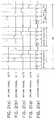
- the light sources LD1 to LD4are driven by the light source control device 55 as shown in Figs. 2(a) to 2(d), respectively, so that the four near infrared light rays with different wavelengths are emitted from the light sources LD1 to LD4 sequentially with the time-sharing method, and the light rays are introduced by the optical fibers 50-1 to 50-4 to the patient's head 40.
- the near infrared lightis partially absorbed by haemoglobin in blood and cytochrome a, a3, in cells and outputted to the optical fiber 53.
- the optical fiber 53introduces the light to the transmission light detection device 54.
- the transmission light detection device 54detects dark light.
- the photomultiplier tube 58 in the transmission light detection device 54is used with a photon-counting device that has high sensitivity and operates at high response speed.
- the output pulse current from the photomultiplier tube 58is sent to the amplitude discriminator 60 through the amplifier 59
- the amplitude discriminator 60eliminates the noise component whose amplitude is smaller than the prescribed amplitude threshold and sends only the signal pulse to the multi-channel photon-counter 61.
- the multi-channel photon-counter 61detects photons only in the periods T o .
- the periods T oare synchronized with the driving signals ACT1 to ACT4 for the respective light sources LD1 to LD4 as shown in Fig.
- the control signal CTLis generated by the detection controller 67,
- the multi-channel photo-counterthen counts detected photon number of every light with each wavelength sent from the optical fiber 53.
- the transmission data of every infrared light with each wavelengthare obtained through the above-described procedure.
- a concrete exampleis as follows; if one cycle is 200 ⁇ sec and N is 10000, the measuring period Mk becomes 2 sec.
- the processor 62performs the subtraction of the dark light component by using the combination of the transmission data and the dark data (T ⁇ 1 , T ⁇ 2 , T ⁇ 3 , T ⁇ 4 , D)M k being stored in the memory 63 after one measuring period M k and the combination of those (T ⁇ 1 , T ⁇ 2 , T ⁇ 3 , T ⁇ 4 , D) Mo at the start of measuring, and calculates the variation rates of the transmission light ⁇ T ⁇ 1 , ⁇ T ⁇ 2 , ⁇ T ⁇ 3 and ⁇ T ⁇ 4 .
- ⁇ T ⁇ jlog [( T ⁇ j - D ) MK / ( T ⁇ j - D ) MO ]
- the use of logarithm in the above calculation of ⁇ T ⁇ jis to express the variation as an optical density.
- the variation of oxygen quantity in the braincan be determined by outputting these detected results from the output device 64. The diagnosis thus is made based on these results.
- an arterial oxygen saturation rate SaO2 in the brainis obtained by the computation of ⁇ HbO2/( ⁇ HbO2 + ⁇ Hb) upon measuring a total amount of haemoglobin ( ⁇ HbO2 + ⁇ Hb) and an amount of oxyhaemoglobin ( ⁇ HbO2) which are modulated in synchronism with heartbeat.
- the heartbeatis pulsation of the heart coincident with ventricular systole.
- EP-A-0290273discloses another method by which the transmission quantity of near infra-red light is modulated in synchronisation with the heartbeat of the patient.
- the heartbeat periodis divided into a number of smaller periods, and the transmission quantity in each small period is accumulated.
- DE-U-9007293discloses a general system for measuring respiration.
- the present inventionhas been made in view of the foregoing, and accordingly it is an object of the present invention to provide a diagnostic apparatus which provides venous blood information representative of brain metabolism, utilization of oxygen in the brain or the like.
- Another object of the present inventionis to provide a diagnostic apparatus which provide both arterial and venous blood information at the same time.
- an apparatus used for diagnosing a living subjectwhich comprises light source for emitting light of different wavelength; light introducing/receiving means for introducing said light into a brain of the living subject and receiving light transmitted through the brain; deriving means for deriving the transmitted light from said introducing/receiving means and outputting a light transmission signal; and, analyzing means arranged to analyze the light transmission signal and provide an operation result, the operation result indicating variations in concentration of oxygenated media ⁇ X02 and disoxygenated media ⁇ X contained in venous blood of the brain, characterised in that the apparatus further comprises: detecting means for detecting occurrences of respirations of the living subject and outputting a respiration signal indicative of occurrences of respirations; operation means arranged to perform an arithmetic operation of K 1 x ⁇ X 02 / ⁇ X + ⁇ X 02 ⁇ where K1 is a predetermined constant, a result of the arithmetic operation indicating an oxygen saturation in the venous blood
- the apparatusfurther comprises second detecting means for detecting occurrences of heartbeats of the living subject and for outputting a heartbeat signal indicative of occurrences of the heartbeats, and second deriving means for deriving the light from the introducing/receiving means in synchronism with the heartbeat signal and for outputting a second modulated light transmission signal indicative of the transmitted light which is modulated by the heartbeat signal.
- the analyzing meansis further arranged to analyze the second modulated light transmission signal and to provide another operation result, said another operation result indicating variations in concentration of oxygenated media ⁇ X02 and disoxygenated media ⁇ X contained in arterial blood of the brain.
- the operation meansis also arranged to perform another arithmetic operation of K 2 x ⁇ X 02 / ⁇ X + ⁇ X 02 ⁇ with respect to the variations in concentration of oxygenated media ⁇ X02 and disoxygenated media ⁇ X contained in arterial blood of the brain, where K2 is a predetermined constant, a result of said another arithmetic operation indicating an oxygen saturation in the arterial blood of the brain.
- the displayis also arranged to display the result of said another arithmetic operation.
- the result of the arithmetic operation and the result of said another arithmetic operationmay be displayed on the display means either selectively or substantially simultaneously.
- the light introduced into the brainis near infrared light, and the near infrared light of different wavelength are repeatedly introduced into the brain each for a predetermined period of time.
- the arithmetic operationis performed when a value of
- the present inventionBased on the finding that the volume of the cerebral venous blood (CVB) is modulated by a respiration which is the act of breathing with the lungs, consisting of inspiration and expiration, the present invention provides an apparatus for detecting an oxygen saturation rate in CVB. Since the modulation of the CVB volume is small in amount, the present invention utilizes an accumulation technique for collecting the modulated CVB volume to thereby improve a signal-to-noise ratio.
- CVBcerebral venous blood
- an apparatus for detecting an oxygen saturation rate in cerebral arterial blood (CAB) in synchronism with heartbeatas disclosed in Japanese Laid-Open Patent publication No. 63-275324 be combined with or incorporated in the CVB oxygen saturation detecting apparatus, so that the oxygen saturations of both the CVB and CAB are obtainable simultaneously and independently of each other.
- a computer system 62has a system bus 66 to which a processor (CPU) 62, a memory 63, an output device 64 and an input device 65 are connected, in the same manner as shown in Fig. 1.
- a period of a respiration signal RSis divided into P-number sub-periods, transmission quantities in each period is accumulated in the repetition and thereby the oxygen saturation in CVB is precisely determined.
- the respiration signal RSis sent from a respiration sensor 72 through the input device 65.
- the respiration signalcan be directly derived from the patient by detecting his or her breathing with the use of a sensor attached to the breast or abdomen portion.
- An aerometeris also usable by placing it near the patient's mouse or nose so as to measure the stream of air. When the patient is breathing with the aid of a respiration machine, a driving signal of the machine is available as the respiration signal.
- each of the periods R1, R2... in the respiration signal RSare divided into P-number intervals, that is, sub-measuring periods m1' to m p '.
- the number Pis selected to be 16 and the respiration period is equally divided into 16 of sub-measuring periods m1' to m16'. For example, if the respiration period S1 is 4.6 sec, each of sub-measuring periods m1' to m16' becomes 287.5 msec. If one cycle CYn is selected to be 200 ⁇ sec, as is described above, each of light sources LD1 to LD4 emits a light 1437.5 times in each of sub-measuring intervals m1' to m16'.
- the multi-channel photon-counter 61counts photon numbers of the transmission light rays at every wavelength of ⁇ 1 to ⁇ 4 and every sub-measuring period of m1' to m p '. This counting is continued over plural respiration periods corresponding to one measuring period M k (where k is an integer) until the time when the counted numbers of all measuring units at each wavelength and in each sub-measuring period exceeds a predetermined value.
- the multi-channel photon-counter 61transfers the counting results in every counting channel to the computer system 56.
- Fig. 6shows the variation of the accumulation values T ⁇ i (1)Acc, T ⁇ i (2)Acc, ..., T ⁇ i (P)Acc, which are obtained by accumulating over one measuring period M k the transmission quantity data T ⁇ i (1)Acc, T ⁇ i (2)Acc, ..., T ⁇ i (P)Acc detected in every sub-measuring period of m1' to m p '.
- the accumulation values of transmission quantity data for the other wavelengths ⁇ 2, ⁇ 3, ⁇ 4also vary in the same manner as Fig. 6.
- the oxygen saturation rate in CVBcan be computed in accordance with an equation given by ⁇ HbO2/( ⁇ HbO2 + ⁇ Hb) upon obtaining data regarding ⁇ HbO2 and ⁇ Hb.
- the oxygen saturation rate in the CABcan be obtained by detecting the transmission light in synchronism with the heartbeat.
- the accumulation of the transmission light data and the calculation of the oxygan saturation in the CABare performed in the similar procedure and thus no detailed description thereof will be necessary.
- the respirationcauses only to change the cerebral venous blood volume whereas the heartbeat causes only to change the cerebral arterial blood volume. Further, the frequency of heartbeat is several times larger than that of respiration. Therefore, the data regarding the CVB and CAB can be discriminated even if the same computer system implements processing and arithmetic operations to obtain the oxygen saturations of both CVB and CAB.
- the oxygen saturations of the CVB and CABcan be displayed on a monitor screen selectively or simultaneously under the aegis of the CPU 62.
- ICUintensive care unit
Landscapes
- Health & Medical Sciences (AREA)
- Life Sciences & Earth Sciences (AREA)
- Physics & Mathematics (AREA)
- Engineering & Computer Science (AREA)
- Heart & Thoracic Surgery (AREA)
- Spectroscopy & Molecular Physics (AREA)
- Biophysics (AREA)
- Pathology (AREA)
- Neurology (AREA)
- Biomedical Technology (AREA)
- Optics & Photonics (AREA)
- Medical Informatics (AREA)
- Molecular Biology (AREA)
- Surgery (AREA)
- Animal Behavior & Ethology (AREA)
- General Health & Medical Sciences (AREA)
- Public Health (AREA)
- Veterinary Medicine (AREA)
- Measurement Of The Respiration, Hearing Ability, Form, And Blood Characteristics Of Living Organisms (AREA)
Description
- The present invention relates generally to a diagnostic apparatus having an oximeter which is used for measuring a quantity of oxygen in brain. More particularly, the invention relates to a diagnostic apparatus wherein the changes of both arterial and venous blood volumes in brain are measured independently of each other, and the respective oxygen saturation rates in the brain are computed based on the measured data and displayed on a monitor screen.
- In general, in diagnosing the function of a body organ, such as the cerebral tissues, the fundamental and important parameters to measure are the oxygen quantity in the body organ and the organ's utilization of oxygen. Supplying body organs with a sufficient quantity of oxygen is indispensable for the growth ability of fetuses and new-born infants. If the supply of oxygen to a fetus is insufficient, the probability that the fetus will not survive or that the new-born infant will die is high. Even if the newborn infant lives, the serious problems in the body organs may remain as sequelae. The insufficiency of oxygen affects every body organ, but especially causes a serious damage in the cerebral tissues.
- To quickly and readily measure a quantity of oxygen supplied to body organs, such as brain, a diagnostic apparatus using near infrared spectroscopy technique has been developed as disclosed, for example, in U.S. Patent No. 4,281,645 issued August 4, 1981. This apparatus allows safe continuous monitoring of changes in blood and tissue oxygenation on an intact organ. This is made possible by observing spectral changes in the tissues caused by oxygenated haemoglobin, deoxygenated haemoglobin and cytochrome.
- As shown in Fig. 3(a), the absorption spectra of near infrared light (700 to 1300 nm), αHbO₂ and αHb by oxyhaemoglobin (HbO₂) and deoxyhaemoglobin (Hb), respectively, are different from each other. And as shown in Fig. 3(b), the absorption spectra αCyO₂ and αCy by oxidized cytochrome a, a₃ (CyO₂) and reduced cytochrome a, a₃ (Cy), respectively, are different from each other. This diagnostic apparatus utilizes the above-described absorption spectra of near infrared light. Four near infrared light rays with different wavelengths, λ1, λ2, λ3 and λ4 (e.g. 775nm, 800nm, 825nm, and 850nm) are applied to one side of the patient's head with a time-sharing method and the transmission light rays from the opposite side of the head are in turn detected. By processing these four detected light rays with the prescribed calculation program, the density variations of oxyhaemoglobin (HbO₂), deoxyhaemoglobin (Hb), oxidized cytochrome a, a₃ (CyO₂) and reduced cytochrome a, a₃ (Cy) are calculated. These parameters, in turn, determine the variation of cerebral oxygen quantity.
- Fig. 1 shows a system outline of a
diagnostic apparatus 45. Theapparatus 45 includes light sources such as laser diodes LD1 to LD4 which emit four near infrared light rays with different wavelengths of λ1,λ2, λ3, and λ4, respectively; a lightsource control device 55 which controls output timing of the light sources LD1 to LD4; optical fibers 50-1 to 50-4 which introduces near infrared light rays emitted by the light sources LD1 to LD4 to a patient'shead 40; an illumination-side fixture 51 which bundles and holds end portions of the optical fibers 50-1 to 50-4; a detection-side fixture 52 which is fitted to the prescribed position of the opposite side of the patient'shead 40; anoptical fiber 53 which is held by the detection-side fixture 52 and introduces transmitted near infrared light from the patient'shead 40; a transmissionlight detection device 54 which measures transmission quantity of near infrared light by counting photons of near infrared light introduced by theoptical fiber 53; and acomputer system 56 which controls the total diagnostic apparatus and determines the variation of oxygen quantity in cerebral tissues based on the transmission quantity of near infrared light. - The
computer system 56 is equipped with a central processing unit (CPU) 62, amemory 63,output devices 64 such as a display and printer, and aninput device 65 such as a keyboard, and these devices are connected to each other by asystem bus 66. The lightsource control device 55 and the transmissionlight detection device 54 are connected to thesystem bus 66 as external I/O's. - The light
source control device 55 receives instructions from thecomputer system 56 and drives the light sources LD1 to LD4 by respective driving signals ACT1 to ACT4 as shown in Figs. 2 (a) to 2(d). As shown therein, one measuring period Mk (k=1, 2,...) consists of N cycles of CY1 to CYn. At a phase φn1 in an arbitrary cycle CYn, no light source of LD1 to LD4 is driven and therefore the patient'shead 40 is not illuminated by the near infrared light from the light sources LD1 to LD4. At the phase φn2 the light source LD1 is driven and the near infrared light with the wavelength of, for example, 775 nm is emitted from it. In the same manner, at the phase φn3 the light source LD2 is driven and the near infrared light with the wavelength of, for example, 800 nm is emitted from it; at the phase φn4 the light source LD3 is driven and the near infrared light with the wavelength of, for example, 825 nm is emitted from it; and at the phase φn5 the light source LD4 is driven and the near infrared light with the wavelength of, for example, 850 nm is emitted from it. In this manner, the lightsource control device 55 drives the light sources LD1 to LD4 sequentially with a time-sharing method. - Referring again to Fig.1, the transmission
light detection device 54 is equipped with afilter 57 which adjusts the quantity of near infrared light outputted tolenses optical fiber 53; aphotomultiplier tube 58 which converts the light from thefilter 57 into pulse current and outputs it; anamplifier 59 which amplifies the pulse current from thephoto multiplier tube 58; an amplitude discriminator 60 which eliminates the pulse current from theamplifier 59 whose amplitude is smaller than the prescribed threshold value; a multichannel photon-counter 61 which detects photon frequency in every channel; adetection controller 67 which controls the temperature of acooler 69 containing thephotomultiplier tube 58. - To use the above-described diagnostic apparatus, the illumination-
side fixture 51 and the detection-side fixture 52 are firmly fitted to the prescribed positions of the patient'shead 40 by using tape or the like. Once fitted, the light sources LD1 to LD4 are driven by the lightsource control device 55 as shown in Figs. 2(a) to 2(d), respectively, so that the four near infrared light rays with different wavelengths are emitted from the light sources LD1 to LD4 sequentially with the time-sharing method, and the light rays are introduced by the optical fibers 50-1 to 50-4 to the patient'shead 40. As bones and soft tissues in the patient'shead 40 are transparent to the near infrared light, the near infrared light is partially absorbed by haemoglobin in blood and cytochrome a, a3, in cells and outputted to theoptical fiber 53. Theoptical fiber 53 introduces the light to the transmissionlight detection device 54. At the phase φn1, no light source of LD1 to LD4 is driven, and therefore, the transmissionlight detection device 54 detects dark light. - The
photomultiplier tube 58 in the transmissionlight detection device 54 is used with a photon-counting device that has high sensitivity and operates at high response speed. The output pulse current from thephotomultiplier tube 58 is sent to the amplitude discriminator 60 through theamplifier 59 The amplitude discriminator 60 eliminates the noise component whose amplitude is smaller than the prescribed amplitude threshold and sends only the signal pulse to the multi-channel photon-counter 61. The multi-channel photon-counter 61 detects photons only in the periods To. The periods To are synchronized with the driving signals ACT1 to ACT4 for the respective light sources LD1 to LD4 as shown in Fig. 2(a) to 2(d) by a control signal CTL as shown in Fig. 2(e). The control signal CTL is generated by thedetection controller 67, The multi-channel photo-counter then counts detected photon number of every light with each wavelength sent from theoptical fiber 53. The transmission data of every infrared light with each wavelength are obtained through the above-described procedure. - As shown in Figs. 2(a) to 2(e), at the phase φn1 in the cycle CYn of light
source control device 55 no light source of LD1 to LD4 is driven, therefore the dark light data d are counted by the transmissionlight detection device 54. At the phases φn2 to φn5 the light sources LD1 to LD4 are sequentially driven with the time-sharing method and the transmissionlight detection device 54 sequentially counts the transmission data tλ1, tλ2, tλ3 and tλ4 of the respective near infrared light rays with different wavelengths λ1, λ2, λ3 and λ4. - The counting of the dark light data D and the transmission data tλ1, tλ2, tλ3 and tλ4 which is sequentially performed in the cycle CYn, is continued N times from CY1 to CYn. That is, one measuring period Mk (k=1,2,...) includes N cycles. A concrete example is as follows; if one cycle is 200 µsec and N is 10000, the measuring period Mk becomes 2 sec. At the time of finishing of one measuring period Mk, the counting result of the dark light data D


computer system 56 and stored in thememory 63. - The
processor 62 performs the subtraction of the dark light component by using the combination of the transmission data and the dark data (Tλ1, Tλ2, Tλ3, Tλ4, D)Mk being stored in thememory 63 after one measuring period Mk and the combination of those (Tλ1, Tλ2, Tλ3, Tλ4, D)Mo at the start of measuring, and calculates the variation rates of the transmission light ΔTλ1, ΔTλ2, ΔTλ3 and ΔTλ4. That is, the variation rates of the transmission light ΔTλ1, ΔTλ2, ΔTλ3 and ΔTλ4 are calculated as:
- Using the above-calculated variation rates of the transmission light ΔTλ1, ΔTλ2, ΔTλ3 and ΔTλ4 density variations of oxyhaemoglobin (HbO2), deoxyhaemoglobin (Hb), oxidized cytochrome a, a₃ (CyO₂) and reduced cytochrome a, a₃ which are expressed as ΔXHbO2, ΔXHb, ΔXCyO2 and ΔXCy, respectively, can be determined. That is, each of density variations of ΔXHbO2 ΔXHb, ΔXCyO2 and ΔXCy is calculated as:

head 40 along the traveling direction of the near infrared light. - As the above-detected density variation components, ΔXHbO2, ΔXHb, ΔXCyO₂ and ΔXCy, reflect the variation of oxygen quantity in the brain, the variation of oxygen quantity in the brain can be determined by outputting these detected results from the
output device 64. The diagnosis thus is made based on these results. - The measured absorption spectra of near infrared light rays primarily dependent on haemoglobin and the absorption spectra is little affected by cytochrome. This is due to the fact that an amount of haemoglobin in body organ is several times as many as an amount of cytochrome and that change of cytochrome from oxydization to deoxydization or vice versa is small in amount in a normal condition because of cytochrome's oxygen affinity which is stronger than haemoglobin. Therefore, it is reasonably assumed that the change of oxygen quantity in body organ is substantially equivalent to the change of haemoglobin density in blood.
- It is important in clinical pathology and it has in fact long been required that data regarding the oxygen saturation rate of the blood flowing through a body organ be given to a clinician to perform diagnosing. However, the above-described apparatus is incapable of providing such data, although it is possible to measure and display the density variations of oxyhaemoglobin (HbO₂), deoxyhaemoglobin (Hb), and oxidized cytochrome (CyO₂) and reduced cytochrome (Cy).
- Here, the oxygen saturation rate of the increased or decreased blood ΔSO₂ to be obtained is defined by a ratio of the density variation of oxyhaemoglobin (HbO₂) to a sum of the density variations of oxyhaemoglobin (HbO₂) and deoxyhaemoglobin (Hb), i.e.,

- One solution to the above problem is proposed in Japanese Laid-Open Patent Publication No. 63-275324 wherein an arterial oxygen saturation rate SaO₂ in the brain is obtained by the computation of ΔHbO₂/(ΔHbO₂ + ΔHb) upon measuring a total amount of haemoglobin (ΔHbO₂ + ΔHb) and an amount of oxyhaemoglobin (ΔHbO₂) which are modulated in synchronism with heartbeat. The heartbeat is pulsation of the heart coincident with ventricular systole.
- According to this technique, while it is possible to provide the arterial oxygen saturation SaO₂ which is representative of change in supply of oxygen to the brain, information regarding venous blood is not available which is representative of brain metabolism, utilization of oxygen in the brain or the like.
- It has also been proposed to obtain the oxygen saturation rate with the use of near infrared spectroscopy technique, wherein the change of total volume of haemoglobin (ΔHbO₂ + ΔHb) is monitored at all times and computation of ΔHbO₂/(ΔHbO₂ + ΔHb) is performed when the total volume of haemoglobin or the blood volume is changed for some reason more than a predetermined level. This technique is advantageous in that oxygen saturation rate is obtained resulting from the change of blood volume which may occur when a new-born infant is applied with pressure caused by aspiration or manoeuvre at the time of birth or when the head portion of the fetus is moved up and down. This technique is particularly advantageous in that information of other than the arterial status is available.
- However, this technique is not applicable to adults or general diagnosing. Further, information regarding both the arterial and venous blood cannot be provided independently of each other.
- The applicant's earlier European patent application, EP-A-0290273, discloses another method by which the transmission quantity of near infra-red light is modulated in synchronisation with the heartbeat of the patient. In this case, the heartbeat period is divided into a number of smaller periods, and the transmission quantity in each small period is accumulated.
- DE-U-9007293 discloses a general system for measuring respiration.
- The present invention has been made in view of the foregoing, and accordingly it is an object of the present invention to provide a diagnostic apparatus which provides venous blood information representative of brain metabolism, utilization of oxygen in the brain or the like.
- Another object of the present invention is to provide a diagnostic apparatus which provide both arterial and venous blood information at the same time.
- To achieve the above and other objects, there is provided an apparatus used for diagnosing a living subject, which comprises light source for emitting light of different wavelength;
light introducing/receiving means for introducing said light into a brain of the living subject and receiving light transmitted through the brain;
deriving means for deriving the transmitted light from said introducing/receiving means and outputting a light transmission signal; and,
analyzing means arranged to analyze the light transmission signal and provide an operation result, the operation result indicating variations in concentration of oxygenated media ΔX₀₂ and disoxygenated media ΔX contained in venous blood of the brain, characterised in that the apparatus further comprises:
detecting means for detecting occurrences of respirations of the living subject and outputting a respiration signal indicative of occurrences of respirations;
operation means arranged to perform an arithmetic operation of
display for displaying the result of the arithmetic operation, in which the deriving means derives the transmitted light from the introducing/receiving means in synchronism with the respiration signal, and outputs a modulated light transmission signal indicative of the light transmission signal when modulated by the respiration signal. - Preferably, the apparatus further comprises second detecting means for detecting occurrences of heartbeats of the living subject and for outputting a heartbeat signal indicative of occurrences of the heartbeats, and second deriving means for deriving the light from the introducing/receiving means in synchronism with the heartbeat signal and for outputting a second modulated light transmission signal indicative of the transmitted light which is modulated by the heartbeat signal. In this case, the analyzing means is further arranged to analyze the second modulated light transmission signal and to provide another operation result, said another operation result indicating variations in concentration of oxygenated media ΔX₀₂ and disoxygenated media ΔX contained in arterial blood of the brain. The operation means is also arranged to perform another arithmetic operation of

- The result of the arithmetic operation and the result of said another arithmetic operation may be displayed on the display means either selectively or substantially simultaneously.
- Preferably, the light introduced into the brain is near infrared light, and the near infrared light of different wavelength are repeatedly introduced into the brain each for a predetermined period of time. The arithmetic operation is performed when a value of |ΔX + ΔX₀₂| is equal to or larger than a predetermined minimum.
- The present invention will be better understood from the following description, given by way of example with reference to the accompanying drawings in which:
- Fig. 1 is a system constitution of a conventional diagnostic apparatus;
- Figs. 2(a) through 2(e) are timing charts of driving signals ACT1 to ACT4 and a control signal CTL, respectively;
- Figs. 3(a) and 3(b) are graphs of absorption spectra of haemoglobin and cytochrome, respectively;
- Fig. 4 is a system constitution of a diagnostic apparatus according to one embodiment of the present invention;
- Figs. 5(a) and 5(b) are a timing chart showing a respiration signal RS and sub-measuring periods, respectively; and
- Fig. 6 is a graph of accumulation values of transmission data which are accumulated over one measuring period.
- Based on the finding that the volume of the cerebral venous blood (CVB) is modulated by a respiration which is the act of breathing with the lungs, consisting of inspiration and expiration, the present invention provides an apparatus for detecting an oxygen saturation rate in CVB. Since the modulation of the CVB volume is small in amount, the present invention utilizes an accumulation technique for collecting the modulated CVB volume to thereby improve a signal-to-noise ratio.
- It is preferable that an apparatus for detecting an oxygen saturation rate in cerebral arterial blood (CAB) in synchronism with heartbeat as disclosed in Japanese Laid-Open Patent publication No. 63-275324 be combined with or incorporated in the CVB oxygen saturation detecting apparatus, so that the oxygen saturations of both the CVB and CAB are obtainable simultaneously and independently of each other.
- In Fig. 4, the same reference numerals or characters are given to the parts as those to the corresponding parts in Fig. 1 and the description for these parts will be omitted.
- In the diagnosing
apparatus 45, acomputer system 62 has asystem bus 66 to which a processor (CPU) 62, amemory 63, anoutput device 64 and aninput device 65 are connected, in the same manner as shown in Fig. 1. As shown in Fig. 5(b), a period of a respiration signal RS is divided into P-number sub-periods, transmission quantities in each period is accumulated in the repetition and thereby the oxygen saturation in CVB is precisely determined. The respiration signal RS is sent from arespiration sensor 72 through theinput device 65. The respiration signal can be directly derived from the patient by detecting his or her breathing with the use of a sensor attached to the breast or abdomen portion. An aerometer is also usable by placing it near the patient's mouse or nose so as to measure the stream of air. When the patient is breathing with the aid of a respiration machine, a driving signal of the machine is available as the respiration signal. - In the
computer system 56, each of the periods R1, R2... in the respiration signal RS are divided into P-number intervals, that is, sub-measuring periods m₁' to mp'. In this embodiment, the number P is selected to be 16 and the respiration period is equally divided into 16 of sub-measuring periods m₁' to m₁₆'. For example, if the respiration period S1 is 4.6 sec, each of sub-measuring periods m₁' to m₁₆' becomes 287.5 msec. If one cycle CYn is selected to be 200 µsec, as is described above, each of light sources LD1 to LD4 emits a light 1437.5 times in each of sub-measuring intervals m₁' to m₁₆'. - The near infrared light rays emitted from the light sources LD1 to LD4 being sequentially driven in one cycle CYn (n = 1 to 1437 or 1438) in one period S1 are attenuated by the patient's
bead 40 and sent to the transmissionlight detection device 54. The multi-channel photon-counter 61 counts photon numbers of the transmission light rays at every wavelength of λ₁ to λ₄ and every sub-measuring period of m₁' to mp'. This counting is continued over plural respiration periods corresponding to one measuring period Mk (where k is an integer) until the time when the counted numbers of all measuring units at each wavelength and in each sub-measuring period exceeds a predetermined value. - When one measuring period Mk is finished, the multi-channel photon-
counter 61 transfers the counting results in every counting channel to thecomputer system 56. The accumulated transmission quantity data at the wavelength λi and in the sub-measuring period mℓ is expressed as Tλi(ℓ)Acc, where i = 1 to 4 and ℓ = 1 to P. - By accumulating transmission quantity data in every sub-measuring period of m₁' to mp' in the above-described procedure, the transmission quantity in each of sub-measuring periods m₁' to mp' becomes large enough to be analyzed and the variation between sub-measuring periods m₁' to mp' caused by the respiration can be clearly detected.
- Paying attention to one wavelength λ₁, Fig. 6 shows the variation of the accumulation values Tλi(1)Acc, Tλi(2)Acc, ..., Tλi(P)Acc, which are obtained by accumulating over one measuring period Mk the transmission quantity data Tλi(1)Acc, Tλi(2)Acc, ..., Tλi(P)Acc detected in every sub-measuring period of m₁' to mp'. The accumulation values of transmission quantity data for the other wavelengths λ₂, λ₃, λ₄ also vary in the same manner as Fig. 6.
- Through the above-described data accumulation, it is capable of obtaining data with excellent signal-to-noise (S/N) ratio. Based on the data thus obtained, the oxygen saturation rate in CVB can be computed in accordance with an equation given by ΔHbO₂/(ΔHbO₂ + ΔHb) upon obtaining data regarding ΔHbO₂ and ΔHb.
- The oxygen saturation rate in the CAB can be obtained by detecting the transmission light in synchronism with the heartbeat. The accumulation of the transmission light data and the calculation of the oxygan saturation in the CAB are performed in the similar procedure and thus no detailed description thereof will be necessary.
- The respiration causes only to change the cerebral venous blood volume whereas the heartbeat causes only to change the cerebral arterial blood volume. Further, the frequency of heartbeat is several times larger than that of respiration. Therefore, the data regarding the CVB and CAB can be discriminated even if the same computer system implements processing and arithmetic operations to obtain the oxygen saturations of both CVB and CAB.
- The oxygen saturations of the CVB and CAB can be displayed on a monitor screen selectively or simultaneously under the aegis of the
CPU 62. In the cases where the respiration and/or heartbeat of the patient is being monitored by another device located, for example in an intensive care unit (ICU), it is not necessary to provide the respiration and/orheartbeat sensors


Claims (6)
- An apparatus (45) used for diagnosing a living subject, the apparatus (45) comprising:
light source (LD1 to LD4) for emitting light of different wavelength;
light introducing/receiving means (50-1 to 50-4, 51 to 53) for introducing said light into a brain of the living subject and receiving light transmitted through the brain;
deriving means (54,62) for deriving the transmitted light from said introducing/receiving means (50-1 to 50-4, 51 to 53) and outputting a light transmission signal; and,
analyzing means (56) arranged to analyze the light transmission signal and provide an operation result, the operation result indicating variations in concentration of oxygenated media ΔX₀₂ and disoxygenated media ΔX contained in venous blood of the brain, characterised in that the apparatus further comprises:
detecting means (72) for detecting occurrences of respirations of the living subject and outputting a respiration signal indicative of occurrences of respirations;
operation means (62) arranged to perform an arithmetic operation of
display (64) for displaying the result of the arithmetic operation, in which the deriving means (54,62) derives the transmitted light from the introducing/receiving (50-1 to 50-4, 51 to 53) means in synchronism with the respiration signal, and outputs a modulated light transmission signal indicative of the light transmission signal when modulated by the respiration signal. - An apparatus (45) according to claim 1, further comprising second detecting means (73) for detecting occurrences of heartbeats of the living subject and for outputting a heartbeat signal indicative of occurrences of the heartbeats, and second deriving means (54,62) for deriving the light from said introducing/receiving means (50-1 to 50-4, 51 to 53) in synchronism with the heartbeat signal and for outputting a second modulated light transmission signal indicative of the transmitted light which is modulated by the heartbeat signal, wherein said analyzing means (56) is further arranged to analyze the second modulated light transmission signal and to provide another operation result, said another operation result indicating variations in concentration of oxygenated media ΔX₀₂ and disoxygenated media ΔX contained in arterial blood of the brain, wherein said operation means (62) is further arranged to perform another arithmetic operation of

- An apparatus (45) according to claim 2, wherein the result of the arithmetic operation and the result of said another arithmetic operation are displayed on said display (64) substantially simultaneously.
- An apparatus (45) according to claim 2, wherein the result of the arithmetic operation and the result of said another arithmetic operation are selectively displayed on said display (64).
- An apparatus (45) according to any one of preceding claims, wherein the light introduced into the brain is near infrared light.
- An apparatus (45) according to any one of preceding claims, wherein the light of different wavelength are repeatedly introduced into the brain each for a predetermined period of time, and wherein the arithmetic operation is performed when a value of |ΔX + ΔX₀₂| is equal to or larger than a predetermined minimum.


Priority Applications (4)
| Application Number | Priority Date | Filing Date | Title |
|---|---|---|---|
| EP91312095AEP0549835B1 (en) | 1991-12-30 | 1991-12-30 | Diagnostic apparatus |
| DE69117964TDE69117964T2 (en) | 1991-12-30 | 1991-12-30 | Diagnostic device |
| US07/853,183US5253646A (en) | 1991-12-30 | 1992-03-18 | Diagnostic apparatus for measuring changes of arterial and venous blood volumes in brain with respiration signal modulation |
| JP4360836AJP2640412B2 (en) | 1991-12-30 | 1992-12-29 | Diagnostic device |
Applications Claiming Priority (1)
| Application Number | Priority Date | Filing Date | Title |
|---|---|---|---|
| EP91312095AEP0549835B1 (en) | 1991-12-30 | 1991-12-30 | Diagnostic apparatus |
Publications (2)
| Publication Number | Publication Date |
|---|---|
| EP0549835A1 EP0549835A1 (en) | 1993-07-07 |
| EP0549835B1true EP0549835B1 (en) | 1996-03-13 |
Family
ID=8208525
Family Applications (1)
| Application Number | Title | Priority Date | Filing Date |
|---|---|---|---|
| EP91312095AExpired - LifetimeEP0549835B1 (en) | 1991-12-30 | 1991-12-30 | Diagnostic apparatus |
Country Status (4)
| Country | Link |
|---|---|
| US (1) | US5253646A (en) |
| EP (1) | EP0549835B1 (en) |
| JP (1) | JP2640412B2 (en) |
| DE (1) | DE69117964T2 (en) |
Families Citing this family (117)
| Publication number | Priority date | Publication date | Assignee | Title |
|---|---|---|---|---|
| US5873821A (en)* | 1992-05-18 | 1999-02-23 | Non-Invasive Technology, Inc. | Lateralization spectrophotometer |
| JP3112025B2 (en)* | 1990-10-26 | 2000-11-27 | 株式会社日立製作所 | Biological measurement device |
| US6549795B1 (en) | 1991-05-16 | 2003-04-15 | Non-Invasive Technology, Inc. | Spectrophotometer for tissue examination |
| US6785568B2 (en)* | 1992-05-18 | 2004-08-31 | Non-Invasive Technology Inc. | Transcranial examination of the brain |
| US5954053A (en)* | 1995-06-06 | 1999-09-21 | Non-Invasive Technology, Inc. | Detection of brain hematoma |
| US5482041A (en)* | 1992-06-05 | 1996-01-09 | Wilk; Peter J. | Medical investigation system and related method |
| JP3107914B2 (en)* | 1992-07-20 | 2000-11-13 | 浜松ホトニクス株式会社 | Apparatus and method for measuring absorption information inside scattering absorber |
| US5447159A (en)* | 1993-02-03 | 1995-09-05 | Massachusetts Institute Of Technology | Optical imaging for specimens having dispersive properties |
| US5995859A (en)* | 1994-02-14 | 1999-11-30 | Nihon Kohden Corporation | Method and apparatus for accurately measuring the saturated oxygen in arterial blood by substantially eliminating noise from the measurement signal |
| US6662033B2 (en)* | 1994-04-01 | 2003-12-09 | Nellcor Incorporated | Pulse oximeter and sensor optimized for low saturation |
| US5685313A (en)* | 1994-05-31 | 1997-11-11 | Brain Monitor Ltd. | Tissue monitor |
| FI98266C (en)* | 1994-11-29 | 1997-05-26 | Jukka Aihonen | A device intended for personal use to monitor life functions |
| DE19612425C2 (en)* | 1995-03-31 | 2000-08-31 | Nihon Kohden Corp | Apparatus for measuring hemoglobin concentration |
| US20060184047A1 (en)* | 1995-11-17 | 2006-08-17 | Yuichi Yamashita | Optical measurement instrument for living body |
| DE19640807A1 (en)* | 1996-10-02 | 1997-09-18 | Siemens Ag | Noninvasive optical detection of oxygen supply to e.g. brain or liver |
| US6018673A (en) | 1996-10-10 | 2000-01-25 | Nellcor Puritan Bennett Incorporated | Motion compatible sensor for non-invasive optical blood analysis |
| US5899857A (en)* | 1997-01-07 | 1999-05-04 | Wilk; Peter J. | Medical treatment method with scanner input |
| US6675031B1 (en) | 1999-04-14 | 2004-01-06 | Mallinckrodt Inc. | Method and circuit for indicating quality and accuracy of physiological measurements |
| US7840257B2 (en) | 2003-01-04 | 2010-11-23 | Non Invasive Technology, Inc. | Examination of biological tissue using non-contact optical probes |
| US6594513B1 (en)* | 2000-01-12 | 2003-07-15 | Paul D. Jobsis | Method and apparatus for determining oxygen saturation of blood in body organs |
| US6701171B2 (en) | 2000-03-31 | 2004-03-02 | Københavns Universitet | Method and apparatus for non-invasive detection of angiogenic and anti-angiogenic activity in living tissue |
| US8224412B2 (en) | 2000-04-17 | 2012-07-17 | Nellcor Puritan Bennett Llc | Pulse oximeter sensor with piece-wise function |
| EP1274343B1 (en) | 2000-04-17 | 2012-08-15 | Nellcor Puritan Bennett LLC | Pulse oximeter sensor with piece-wise function |
| US6985763B2 (en)* | 2001-01-19 | 2006-01-10 | Tufts University | Method for measuring venous oxygen saturation |
| US6748254B2 (en) | 2001-10-12 | 2004-06-08 | Nellcor Puritan Bennett Incorporated | Stacked adhesive optical sensor |
| US7190986B1 (en) | 2002-10-18 | 2007-03-13 | Nellcor Puritan Bennett Inc. | Non-adhesive oximeter sensor for sensitive skin |
| WO2005025399A2 (en) | 2003-09-12 | 2005-03-24 | Or-Nim Medical Ltd. | Noninvasive optical monitoring of region of interest |
| EP1688090B1 (en)* | 2003-11-26 | 2013-07-03 | Hitachi Medical Corporation | Biological light measuring apparatus and method |
| US7162288B2 (en) | 2004-02-25 | 2007-01-09 | Nellcor Purtain Bennett Incorporated | Techniques for detecting heart pulses and reducing power consumption in sensors |
| US7277741B2 (en)* | 2004-03-09 | 2007-10-02 | Nellcor Puritan Bennett Incorporated | Pulse oximetry motion artifact rejection using near infrared absorption by water |
| US20050228253A1 (en)* | 2004-04-07 | 2005-10-13 | Nellcor Puritan Bennett Incorporated | Photoplethysmography with a spatially homogenous multi-color source |
| JP4012900B2 (en)* | 2004-10-21 | 2007-11-21 | 株式会社日立製作所 | Biological light measurement device |
| US7865223B1 (en) | 2005-03-14 | 2011-01-04 | Peter Bernreuter | In vivo blood spectrometry |
| US8055321B2 (en) | 2005-03-14 | 2011-11-08 | Peter Bernreuter | Tissue oximetry apparatus and method |
| PL1863387T3 (en) | 2005-03-16 | 2013-11-29 | Or Nim Medical Ltd | Noninvasive measurements in a human body |
| US7657295B2 (en) | 2005-08-08 | 2010-02-02 | Nellcor Puritan Bennett Llc | Medical sensor and technique for using the same |
| US7590439B2 (en) | 2005-08-08 | 2009-09-15 | Nellcor Puritan Bennett Llc | Bi-stable medical sensor and technique for using the same |
| US7657294B2 (en) | 2005-08-08 | 2010-02-02 | Nellcor Puritan Bennett Llc | Compliant diaphragm medical sensor and technique for using the same |
| US20070060808A1 (en) | 2005-09-12 | 2007-03-15 | Carine Hoarau | Medical sensor for reducing motion artifacts and technique for using the same |
| US7869850B2 (en) | 2005-09-29 | 2011-01-11 | Nellcor Puritan Bennett Llc | Medical sensor for reducing motion artifacts and technique for using the same |
| US7899510B2 (en) | 2005-09-29 | 2011-03-01 | Nellcor Puritan Bennett Llc | Medical sensor and technique for using the same |
| US7904130B2 (en) | 2005-09-29 | 2011-03-08 | Nellcor Puritan Bennett Llc | Medical sensor and technique for using the same |
| US8092379B2 (en) | 2005-09-29 | 2012-01-10 | Nellcor Puritan Bennett Llc | Method and system for determining when to reposition a physiological sensor |
| US7483731B2 (en) | 2005-09-30 | 2009-01-27 | Nellcor Puritan Bennett Llc | Medical sensor and technique for using the same |
| US8062221B2 (en) | 2005-09-30 | 2011-11-22 | Nellcor Puritan Bennett Llc | Sensor for tissue gas detection and technique for using the same |
| US7881762B2 (en) | 2005-09-30 | 2011-02-01 | Nellcor Puritan Bennett Llc | Clip-style medical sensor and technique for using the same |
| US7555327B2 (en) | 2005-09-30 | 2009-06-30 | Nellcor Puritan Bennett Llc | Folding medical sensor and technique for using the same |
| US7486979B2 (en) | 2005-09-30 | 2009-02-03 | Nellcor Puritan Bennett Llc | Optically aligned pulse oximetry sensor and technique for using the same |
| US8233954B2 (en) | 2005-09-30 | 2012-07-31 | Nellcor Puritan Bennett Llc | Mucosal sensor for the assessment of tissue and blood constituents and technique for using the same |
| US7477924B2 (en) | 2006-05-02 | 2009-01-13 | Nellcor Puritan Bennett Llc | Medical sensor and technique for using the same |
| US7522948B2 (en) | 2006-05-02 | 2009-04-21 | Nellcor Puritan Bennett Llc | Medical sensor and technique for using the same |
| US8073518B2 (en) | 2006-05-02 | 2011-12-06 | Nellcor Puritan Bennett Llc | Clip-style medical sensor and technique for using the same |
| US8145288B2 (en) | 2006-08-22 | 2012-03-27 | Nellcor Puritan Bennett Llc | Medical sensor for reducing signal artifacts and technique for using the same |
| US8219170B2 (en) | 2006-09-20 | 2012-07-10 | Nellcor Puritan Bennett Llc | System and method for practicing spectrophotometry using light emitting nanostructure devices |
| US8396527B2 (en) | 2006-09-22 | 2013-03-12 | Covidien Lp | Medical sensor for reducing signal artifacts and technique for using the same |
| US8195264B2 (en) | 2006-09-22 | 2012-06-05 | Nellcor Puritan Bennett Llc | Medical sensor for reducing signal artifacts and technique for using the same |
| US8175671B2 (en) | 2006-09-22 | 2012-05-08 | Nellcor Puritan Bennett Llc | Medical sensor for reducing signal artifacts and technique for using the same |
| US7869849B2 (en) | 2006-09-26 | 2011-01-11 | Nellcor Puritan Bennett Llc | Opaque, electrically nonconductive region on a medical sensor |
| US7574245B2 (en) | 2006-09-27 | 2009-08-11 | Nellcor Puritan Bennett Llc | Flexible medical sensor enclosure |
| US7796403B2 (en) | 2006-09-28 | 2010-09-14 | Nellcor Puritan Bennett Llc | Means for mechanical registration and mechanical-electrical coupling of a faraday shield to a photodetector and an electrical circuit |
| US7890153B2 (en) | 2006-09-28 | 2011-02-15 | Nellcor Puritan Bennett Llc | System and method for mitigating interference in pulse oximetry |
| US8068891B2 (en) | 2006-09-29 | 2011-11-29 | Nellcor Puritan Bennett Llc | Symmetric LED array for pulse oximetry |
| US7476131B2 (en) | 2006-09-29 | 2009-01-13 | Nellcor Puritan Bennett Llc | Device for reducing crosstalk |
| US7680522B2 (en) | 2006-09-29 | 2010-03-16 | Nellcor Puritan Bennett Llc | Method and apparatus for detecting misapplied sensors |
| US7684842B2 (en) | 2006-09-29 | 2010-03-23 | Nellcor Puritan Bennett Llc | System and method for preventing sensor misuse |
| US8175667B2 (en) | 2006-09-29 | 2012-05-08 | Nellcor Puritan Bennett Llc | Symmetric LED array for pulse oximetry |
| US8265724B2 (en) | 2007-03-09 | 2012-09-11 | Nellcor Puritan Bennett Llc | Cancellation of light shunting |
| US7894869B2 (en) | 2007-03-09 | 2011-02-22 | Nellcor Puritan Bennett Llc | Multiple configuration medical sensor and technique for using the same |
| US8280469B2 (en) | 2007-03-09 | 2012-10-02 | Nellcor Puritan Bennett Llc | Method for detection of aberrant tissue spectra |
| US7541602B2 (en) | 2007-06-04 | 2009-06-02 | Or-Nim Medical Ltd. | System and method for noninvasively monitoring conditions of a subject |
| US8346328B2 (en) | 2007-12-21 | 2013-01-01 | Covidien Lp | Medical sensor and technique for using the same |
| US8352004B2 (en) | 2007-12-21 | 2013-01-08 | Covidien Lp | Medical sensor and technique for using the same |
| US8366613B2 (en) | 2007-12-26 | 2013-02-05 | Covidien Lp | LED drive circuit for pulse oximetry and method for using same |
| US8577434B2 (en) | 2007-12-27 | 2013-11-05 | Covidien Lp | Coaxial LED light sources |
| US8442608B2 (en) | 2007-12-28 | 2013-05-14 | Covidien Lp | System and method for estimating physiological parameters by deconvolving artifacts |
| US8452364B2 (en) | 2007-12-28 | 2013-05-28 | Covidien LLP | System and method for attaching a sensor to a patient's skin |
| US8070508B2 (en) | 2007-12-31 | 2011-12-06 | Nellcor Puritan Bennett Llc | Method and apparatus for aligning and securing a cable strain relief |
| US8092993B2 (en) | 2007-12-31 | 2012-01-10 | Nellcor Puritan Bennett Llc | Hydrogel thin film for use as a biosensor |
| US8897850B2 (en) | 2007-12-31 | 2014-11-25 | Covidien Lp | Sensor with integrated living hinge and spring |
| US8199007B2 (en) | 2007-12-31 | 2012-06-12 | Nellcor Puritan Bennett Llc | Flex circuit snap track for a biometric sensor |
| US8437822B2 (en) | 2008-03-28 | 2013-05-07 | Covidien Lp | System and method for estimating blood analyte concentration |
| US8112375B2 (en) | 2008-03-31 | 2012-02-07 | Nellcor Puritan Bennett Llc | Wavelength selection and outlier detection in reduced rank linear models |
| US7880884B2 (en) | 2008-06-30 | 2011-02-01 | Nellcor Puritan Bennett Llc | System and method for coating and shielding electronic sensor components |
| US8071935B2 (en) | 2008-06-30 | 2011-12-06 | Nellcor Puritan Bennett Llc | Optical detector with an overmolded faraday shield |
| US7887345B2 (en) | 2008-06-30 | 2011-02-15 | Nellcor Puritan Bennett Llc | Single use connector for pulse oximetry sensors |
| US8203438B2 (en) | 2008-07-29 | 2012-06-19 | Masimo Corporation | Alarm suspend system |
| US8364220B2 (en) | 2008-09-25 | 2013-01-29 | Covidien Lp | Medical sensor and technique for using the same |
| US8914088B2 (en) | 2008-09-30 | 2014-12-16 | Covidien Lp | Medical sensor and technique for using the same |
| US8423112B2 (en) | 2008-09-30 | 2013-04-16 | Covidien Lp | Medical sensor and technique for using the same |
| US8417309B2 (en) | 2008-09-30 | 2013-04-09 | Covidien Lp | Medical sensor |
| WO2010056973A1 (en) | 2008-11-14 | 2010-05-20 | Nonin Medical, Inc. | Optical sensor path selection |
| JP5196323B2 (en)* | 2009-02-23 | 2013-05-15 | 日本光電工業株式会社 | Blood oxygen saturation measuring device |
| US8452366B2 (en) | 2009-03-16 | 2013-05-28 | Covidien Lp | Medical monitoring device with flexible circuitry |
| US8221319B2 (en) | 2009-03-25 | 2012-07-17 | Nellcor Puritan Bennett Llc | Medical device for assessing intravascular blood volume and technique for using the same |
| US8509869B2 (en) | 2009-05-15 | 2013-08-13 | Covidien Lp | Method and apparatus for detecting and analyzing variations in a physiologic parameter |
| US8634891B2 (en) | 2009-05-20 | 2014-01-21 | Covidien Lp | Method and system for self regulation of sensor component contact pressure |
| US8505821B2 (en) | 2009-06-30 | 2013-08-13 | Covidien Lp | System and method for providing sensor quality assurance |
| US8311601B2 (en) | 2009-06-30 | 2012-11-13 | Nellcor Puritan Bennett Llc | Reflectance and/or transmissive pulse oximeter |
| US9010634B2 (en) | 2009-06-30 | 2015-04-21 | Covidien Lp | System and method for linking patient data to a patient and providing sensor quality assurance |
| US8391941B2 (en) | 2009-07-17 | 2013-03-05 | Covidien Lp | System and method for memory switching for multiple configuration medical sensor |
| US8417310B2 (en) | 2009-08-10 | 2013-04-09 | Covidien Lp | Digital switching in multi-site sensor |
| US8428675B2 (en) | 2009-08-19 | 2013-04-23 | Covidien Lp | Nanofiber adhesives used in medical devices |
| WO2011109312A2 (en) | 2010-03-01 | 2011-09-09 | Masimo Corporation | Adaptive alarm system |
| US8391943B2 (en) | 2010-03-31 | 2013-03-05 | Covidien Lp | Multi-wavelength photon density wave system using an optical switch |
| US7884933B1 (en) | 2010-05-05 | 2011-02-08 | Revolutionary Business Concepts, Inc. | Apparatus and method for determining analyte concentrations |
| US9775545B2 (en) | 2010-09-28 | 2017-10-03 | Masimo Corporation | Magnetic electrical connector for patient monitors |
| EP2621333B1 (en) | 2010-09-28 | 2015-07-29 | Masimo Corporation | Depth of consciousness monitor including oximeter |
| US20130066173A1 (en)* | 2011-09-09 | 2013-03-14 | Nellcor Puritan Bennett Ireland | Venous oxygen saturation systems and methods |
| US9597022B2 (en)* | 2011-09-09 | 2017-03-21 | Nellcor Puritan Bennett Ireland | Venous oxygen saturation systems and methods |
| CN103845070B (en)* | 2012-12-07 | 2018-08-03 | 上海联影医疗科技有限公司 | PET-CT scanning means and its control method |
| US10154815B2 (en) | 2014-10-07 | 2018-12-18 | Masimo Corporation | Modular physiological sensors |
| US10328202B2 (en) | 2015-02-04 | 2019-06-25 | Covidien Lp | Methods and systems for determining fluid administration |
| US10499835B2 (en) | 2015-03-24 | 2019-12-10 | Covidien Lp | Methods and systems for determining fluid responsiveness in the presence of noise |
| US11350859B2 (en)* | 2016-12-20 | 2022-06-07 | Koninklijke Philips N.V. | Patient monitoring |
| US10340408B1 (en)* | 2018-05-17 | 2019-07-02 | Hi Llc | Non-invasive wearable brain interface systems including a headgear and a plurality of self-contained photodetector units configured to removably attach to the headgear |
| JP7262987B2 (en) | 2018-12-10 | 2023-04-24 | 浜松ホトニクス株式会社 | Concentration measuring device and method of operating the concentration measuring device |
| CN117322876A (en)* | 2023-10-27 | 2024-01-02 | 广东省人民医院 | Cerebral oxygen supply and demand monitoring system, method and medium based on artery and vein parameters of neck |
Family Cites Families (16)
| Publication number | Priority date | Publication date | Assignee | Title |
|---|---|---|---|---|
| DE907293C (en)* | 1950-02-25 | 1954-03-22 | Hoffmann La Roche | Process for the preparation of polysulfuric acid esters and salts thereof |
| US4281645A (en)* | 1977-06-28 | 1981-08-04 | Duke University, Inc. | Method and apparatus for monitoring metabolism in body organs |
| US4444498A (en)* | 1981-02-27 | 1984-04-24 | Bentley Laboratories | Apparatus and method for measuring blood oxygen saturation |
| JPS63275324A (en)* | 1987-05-08 | 1988-11-14 | Hamamatsu Photonics Kk | Diagnostic apparatus |
| US4907876A (en)* | 1987-05-08 | 1990-03-13 | Hamamatsu Photonics Kabushiki Kaisha | Examination apparatus for measuring oxygenation in body organs |
| JP2562894B2 (en)* | 1987-05-08 | 1996-12-11 | 浜松ホトニクス株式会社 | Diagnostic device |
| US5103829A (en)* | 1987-05-08 | 1992-04-14 | Hamamatsu Photonics Kabushiki Kaisha | Examination apparatus for measuring oxygenation in body organs |
| JPS63277038A (en)* | 1987-05-08 | 1988-11-15 | Hamamatsu Photonics Kk | Diagnostic apparatus |
| JPH0165007U (en)* | 1987-10-20 | 1989-04-26 | ||
| US4960126A (en)* | 1988-01-15 | 1990-10-02 | Criticare Systems, Inc. | ECG synchronized pulse oximeter |
| JPH0221289A (en)* | 1988-07-09 | 1990-01-24 | Tokyo Gas Co Ltd | How to detect buried pipes |
| US5090415A (en)* | 1989-02-14 | 1992-02-25 | Hamamatsu Photonics Kabushiki Kaisha | Examination apparatus |
| CN1049287A (en)* | 1989-05-24 | 1991-02-20 | 住友电气工业株式会社 | The treatment conduit |
| JPH0335114A (en)* | 1989-06-30 | 1991-02-15 | Komatsu Ltd | Position measuring device for underground digging machine |
| EP0419729A1 (en)* | 1989-09-29 | 1991-04-03 | Siemens Aktiengesellschaft | Position finding of a catheter by means of non-ionising fields |
| DE9007293U1 (en)* | 1990-06-29 | 1990-09-20 | Ryba, Jan, 6705 Deidesheim | Oxygen pulse respirograph |
- 1991
- 1991-12-30EPEP91312095Apatent/EP0549835B1/ennot_activeExpired - Lifetime
- 1991-12-30DEDE69117964Tpatent/DE69117964T2/ennot_activeExpired - Lifetime
- 1992
- 1992-03-18USUS07/853,183patent/US5253646A/ennot_activeExpired - Lifetime
- 1992-12-29JPJP4360836Apatent/JP2640412B2/ennot_activeExpired - Fee Related
Also Published As
| Publication number | Publication date |
|---|---|
| JP2640412B2 (en) | 1997-08-13 |
| DE69117964D1 (en) | 1996-04-18 |
| JPH05245129A (en) | 1993-09-24 |
| DE69117964T2 (en) | 1996-07-25 |
| EP0549835A1 (en) | 1993-07-07 |
| US5253646A (en) | 1993-10-19 |
Similar Documents
| Publication | Publication Date | Title |
|---|---|---|
| EP0549835B1 (en) | Diagnostic apparatus | |
| EP0497021A1 (en) | Oximeter with monitor | |
| Zourabian et al. | Trans-abdominal monitoring of fetal arterial blood oxygenation using pulse oximetry | |
| US4908762A (en) | Oximeter with system for testing transmission path | |
| US4901238A (en) | Oximeter with monitor for detecting probe dislodgement | |
| US5766127A (en) | Method and apparatus for improved photoplethysmographic perfusion-index monitoring | |
| US6018674A (en) | Fast-turnoff photodiodes with switched-gain preamplifiers in photoplethysmographic measurement instruments | |
| US4281645A (en) | Method and apparatus for monitoring metabolism in body organs | |
| US7006856B2 (en) | Signal quality metrics design for qualifying data for a physiological monitor | |
| US5111817A (en) | Noninvasive system and method for enhanced arterial oxygen saturation determination and arterial blood pressure monitoring | |
| US7047055B2 (en) | Fetal pulse oximetry | |
| US6526301B2 (en) | Direct to digital oximeter and method for calculating oxygenation levels | |
| EP0615723A1 (en) | Method and apparatus for measuring blood flow | |
| US8649838B2 (en) | Wavelength switching for pulse oximetry | |
| JP2562894B2 (en) | Diagnostic device | |
| JPH0584233A (en) | In-vivo oxygen measuring system | |
| JPS63252239A (en) | reflective oximeter | |
| JPH01500493A (en) | Multi-pulse oxygen concentration measurement method and device | |
| EP0512987A4 (en) | Enhanced arterial oxygen saturation determination and arterial blood pressure monitoring | |
| JPH10216114A (en) | Degree of oxygen saturation measuring apparatus | |
| EP0555553A2 (en) | Improved arterial blood monitoring system | |
| EP0290273A1 (en) | Examination apparatus for measuring oxygenation | |
| EP0290278A1 (en) | Examination apparatus for measuring oxygenation | |
| US5203342A (en) | Peripheral blood circulation state detecting apparatus | |
| JP2002228579A (en) | Hemoglobin concentration measuring device |
Legal Events
| Date | Code | Title | Description |
|---|---|---|---|
| PUAI | Public reference made under article 153(3) epc to a published international application that has entered the european phase | Free format text:ORIGINAL CODE: 0009012 | |
| 17P | Request for examination filed | Effective date:19921028 | |
| AK | Designated contracting states | Kind code of ref document:A1 Designated state(s):DE FR GB | |
| 17Q | First examination report despatched | Effective date:19940906 | |
| GRAH | Despatch of communication of intention to grant a patent | Free format text:ORIGINAL CODE: EPIDOS IGRA | |
| GRAA | (expected) grant | Free format text:ORIGINAL CODE: 0009210 | |
| AK | Designated contracting states | Kind code of ref document:B1 Designated state(s):DE FR GB | |
| REF | Corresponds to: | Ref document number:69117964 Country of ref document:DE Date of ref document:19960418 | |
| ET | Fr: translation filed | ||
| PLBE | No opposition filed within time limit | Free format text:ORIGINAL CODE: 0009261 | |
| STAA | Information on the status of an ep patent application or granted ep patent | Free format text:STATUS: NO OPPOSITION FILED WITHIN TIME LIMIT | |
| 26N | No opposition filed | ||
| REG | Reference to a national code | Ref country code:GB Ref legal event code:IF02 | |
| PGFP | Annual fee paid to national office [announced via postgrant information from national office to epo] | Ref country code:FR Payment date:20081212 Year of fee payment:18 | |
| PGFP | Annual fee paid to national office [announced via postgrant information from national office to epo] | Ref country code:GB Payment date:20091230 Year of fee payment:19 | |
| PGFP | Annual fee paid to national office [announced via postgrant information from national office to epo] | Ref country code:DE Payment date:20091224 Year of fee payment:19 | |
| REG | Reference to a national code | Ref country code:FR Ref legal event code:ST Effective date:20100831 | |
| PG25 | Lapsed in a contracting state [announced via postgrant information from national office to epo] | Ref country code:FR Free format text:LAPSE BECAUSE OF NON-PAYMENT OF DUE FEES Effective date:20091231 | |
| GBPC | Gb: european patent ceased through non-payment of renewal fee | Effective date:20101230 | |
| REG | Reference to a national code | Ref country code:DE Ref legal event code:R119 Ref document number:69117964 Country of ref document:DE Effective date:20110701 | |
| PG25 | Lapsed in a contracting state [announced via postgrant information from national office to epo] | Ref country code:GB Free format text:LAPSE BECAUSE OF NON-PAYMENT OF DUE FEES Effective date:20101230 Ref country code:DE Free format text:LAPSE BECAUSE OF NON-PAYMENT OF DUE FEES Effective date:20110701 |