EP0547755B1 - Planar support for material mounted to a frame and method of use - Google Patents
Planar support for material mounted to a frame and method of useDownload PDFInfo
- Publication number
- EP0547755B1 EP0547755B1EP92310239AEP92310239AEP0547755B1EP 0547755 B1EP0547755 B1EP 0547755B1EP 92310239 AEP92310239 AEP 92310239AEP 92310239 AEP92310239 AEP 92310239AEP 0547755 B1EP0547755 B1EP 0547755B1
- Authority
- EP
- European Patent Office
- Prior art keywords
- base
- further characterized
- frame
- plane
- support means
- Prior art date
- Legal status (The legal status is an assumption and is not a legal conclusion. Google has not performed a legal analysis and makes no representation as to the accuracy of the status listed.)
- Expired - Lifetime
Links
Images


Classifications
- B—PERFORMING OPERATIONS; TRANSPORTING
- B41—PRINTING; LINING MACHINES; TYPEWRITERS; STAMPS
- B41F—PRINTING MACHINES OR PRESSES
- B41F15/00—Screen printers
- B41F15/08—Machines
- B41F15/10—Machines for multicolour printing
- B—PERFORMING OPERATIONS; TRANSPORTING
- B41—PRINTING; LINING MACHINES; TYPEWRITERS; STAMPS
- B41C—PROCESSES FOR THE MANUFACTURE OR REPRODUCTION OF PRINTING SURFACES
- B41C1/00—Forme preparation
- B41C1/14—Forme preparation for stencil-printing or silk-screen printing
- B—PERFORMING OPERATIONS; TRANSPORTING
- B41—PRINTING; LINING MACHINES; TYPEWRITERS; STAMPS
- B41M—PRINTING, DUPLICATING, MARKING, OR COPYING PROCESSES; COLOUR PRINTING
- B41M1/00—Inking and printing with a printer's forme
- B41M1/12—Stencil printing; Silk-screen printing
Definitions
- the present inventionresides in a system for supporting a layer of material in a given plane and deals more particularly with a material hold down and support system for use in an apparatus wherein an image is automatically drawn on a surface in a silk screen printing process in which apparatus is provided a means for supporting a printing surface of the screen in a given plane.
- an emulsionis formed on the screen so that a desired resist is created to provide a backdrop upon which an image can be formed.
- PRINTING SCREEN AND METHOD AND APPARATUS FOR ITS MANUFACTUREit has been contemplated to use a single apparatus for generating a plurality of masks each setting out a pattern piece or pieces of the design to be printed in a designated color. This is done by passing a print head over the emulsion to print directly on it and ultimately cause a negative image to be developed in the emulsion. Subsequently, the developed emulsion is used to print the image onto an article.
- the emulsionis spaced only about 1mm (0.04 inch) below the print head during a plotting operation and therefore it is extremely important to maintain this spaced relationship in order to avoid damaging or impairing the plotting operation that occurs during this process.
- the screenis stapled to a frame and such fasteners have damaged the print head as well.
- the frames upon which the screens are mountedare usually warped and this also undesirably contributes to the a non-planar printing surface presented by the screen.
- a system for supporting in a given plane a thin layer of material mounted to a frameincludes a base having an accurately disposed upwardly facing support defining a plane to which the material conforms, a first coordinate axis and a second coordinate axis each of which axes being orthogonally oriented relative to one another and disposed relative to the base.
- a means referencing the planar dimension of said baseprovides a planar support for supporting a layer of material above the base in a given plane.
- the systemfurther includes first clamp means for holding a portion of the mounting frame and being disposed along one of the first and second coordinate axes in registration therewith; and second clamp means for holding the frame and drawing it below the given plane and for causing the layer of material overlain on the support means to conform to the generally planar dimension provided by the support means.
- Locating meansis provided and is fixed relative to the base and associated with the other of the first and second coordinate axes for locating the layer of material in registration therewith.
- the systemmay be used in combination with a coordinate controlled printing head disposed for movement in a plane located above and parallel to the given plane.
- Fig. 1is a fragmentary perspective view showing the apparatus for automatically making a printing screen by a direct imaging process with its cover removed.
- Fig. 2is a perspective view of a screen used in the apparatus of Fig. 1.
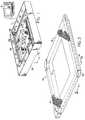
- Fig. 3is a perspective view of the support system employed in the apparatus of Fig. 1.
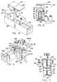
- Fig. 4is a partial fragmentary perspective view of a Y support carriage clamping assembly.
- Fig. 5is a partial fragmentary front elevational view of the assembly of Fig. 4.
- Fig. 6is a partial fragmentary perspective view of an X carriage clamping assembly.
- Fig. 7is a front elevational view of the assembly of Fig. 6.
- Fig. 8ais a perspective view of the support box.
- Fig. 8bis a partially fragmentary view of a corner connection in the box of Fig. 8a.
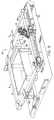
- Fig. 9is a perspective view of the support system of Fig. 3, in this case showing a frame on which is provided an emulsion layer overlay.
- Fig. 10is a vertical sectional view taken through a screen as it is supported in the system embodying the invention.
- Figure 1illustrates an apparatus 1 according to the invention for making a printing screen.
- the apparatusincludes a controller which may be an integral stand alone device or may be a separate computer such as shown at 9, a support assembly 10 which supports a screen 14 within the apparatus 1, and an ink jet printing head 16 which is supported above the screen 14 for movement in a plane generally parallel thereto.
- the printing head 16is supported on a pen carriage 28 for movement along the illustrated X and Y-coordinate printing axes.
- the carriage 28is slidably mounted on a guide rail 29 which extends across the frame 18 and is in turn slidably mounted at each of its ends for movement along ways 27,27.
- An X direction drive motor 33is driveably connected to the pen carriage 28 by means of a drive belt 26 and pulleys 25,25 to move the carriage in the X-coordinate direction while in the same manner the guide rail 29 is moved in the Y-coordinate direction.
- the apparatus 1prints an image, such as the graphic 19 directly onto a light-sensitive emulsion layer 21 before exposing it to light. Thereafter, the emulsion is exposed such that those portions of the emulsion that are not covered by ink or other opaque substance harden. A dissolving solution is then applied to the emulsion and the portions of the emulsion which were covered by the opaque material are dissolved.
- This processis important to the appreciation of the present invention in that it should be understood that several screens are usually used to create a painting on an article surface with each screen being used as a mask through which a given color is deposited. As such, it is highly important that each screen he capable of being held in the apparatus 1 in precisely the same registration as the preceding and following ones thus effecting automatic superposition of the printing material by locating a common reference point.
- the screen 14is mounted to a frame 6 and is comprised of a woven fabric 41, generally of polyester or nylon although silk is sometimes still used, stretched tightly over and affixed to a wooden or metal frame 6 to define a printing surface S .
- the frame 6may take many different forms, but in the preferred embodiment, it has a leading edge 13 suitably sized and configured to be received within an appropriately sized and shaped holder provided in accordance with the invention
- An unexposed light-sensitive emulsion layer 21is applied to the printing surface S of the screen.
- the emulsion layermay be applied to the surface S in many different forms, such as, for example, a viscous liquid which is subsequently allowed to dry and harden.
- the emulsion layer 21is preferably formed on the screen 14 such that it leaves exposed a perimeter area collectively defined by margins M , M having, for example, a width equalling about 50mm (2 inches).
- margins Mmay be used to aid in deflecting the frame below the travel path of the head 16.
- the printing head 16is controllably activated in conjunction with the movement generated by the drive motors in response to the print commands generated and transmitted by the control computer in accordance with data entered into the computer. In this manner, the printing head is translated over the entire surface of the screen to print the graphic 19 directly on the emulsion layer 21 and to precisely and automatically position the graphic with respect to the screen.
- the printing head 16is an ink jet printing head, but the apparatus for practicing the invention is in no way limited in this regard. For example, a thermal printing head and an associated thermal printing ribbon may be employed instead. In the case where an ink jet printing head is used to print the graphic on the emulsion layer it has been found particularly advantageous to provide the emulsion layer with an ink receptive material prior to printing the graphic.
- the support assembly 10 for supporting the screen 14includes a support box 30, a base 32 having a highly accurate planar surface on which the box rests defines the plane ultimately presented to the screen 14, first and second ways 34 and 36 disposed along axes extending parallel to the Y-coordinate direction and spaced from each other generally widthwise of the apparatus 1, and a Y support carriage 38 carrying first and second clamping assemblies 40 and 42 disposed at opposite ends thereof and extending transversely between the first and second ways 34 and 36.
- the support assembly 10further includes first and second X-support carriage assemblies 44 and 46 slidably received within a way 48 fixed to the base 32 and disposed in the X coordinate direction and along which each of the first and second X support carriage assemblies is selectively positionable.
- the first and second Y-coordinate direction ways 34 and 36extend lengthwise along the base 32 of the apparatus 1, while the X-coordinate direction way 48 extends widthwise thereof to present a work area sufficient to accept different frame sizes which may be used in the creating of a printing screen.
- the support assemblyfurther includes a locating block 140 which provides a point for registering the frame 6 along the X coordinate direction. This feature taken in conjunction with a similar feature provided in the X-support carriage assemblies 44 and 46 is important as will hereinafter become apparent in that it provides a means by which uniform registration with the apparatus 1 between different screens can be achieved.
- the Y-support carriage 38includes an elongate transverse member 62 connected at its ends to an elongate block 54,54 in which are housed two tracking wheels 56,56 disposed at opposite ends thereof.
- the tracking wheels 56,56extend outwardly of the end faces 58,58 of each of the blocks and the member 62 is sized sufficiently lengthwise so as to cause an extending portion of each of the tracking wheels 56,56 to be received within a correspondingly sized and shaped longitudinally extending channel 60,60 which defines each of the ways 34 and 36.
- the Y-support carriage 38is thus seated within the ways 34,36 against skewing, yet is capable of moving freely in the illustrated Y coordinate direction.
- a T-shaped retaining groove 64formed along the upwardly extending face of the transverse member 62 is a T-shaped retaining groove 64 correspondingly sized and shaped to receive a mating portion 63 depending from each of the first and second clamping assemblies 40,42 thereby effecting free sliding movement within the groove 64 yet constraining the assemblies from being moved upwardly.
- Each of the first and second clamping assemblies 40 and 42is further comprised of a base or a block portion 70,70, having an opening 74 formed through the top end thereof and being suitably sized for journalling a shaft 76 received therein.
- the shaft 76is freely rotatably journalled within the block 70 but is biased upwardly by an internal spring 78 acting between the shaft 76 and a lower plate 80 and has an upper limit stop 82 defining its upper travel limit.
- a holding plate 84cantilevered therefrom to coact with a juxtaposed portion of the frame 6.
- the clamping assemblies 40,42further include a limit mechanism 88 for limiting the upward travel of the shaft 76 above the block portion 70,70.
- the limit mechanism 88includes a lever 90 having a slightly oversized opening 92 formed therein, a spring member 94 supported on the base portion 70 and acting against the lever 90.
- the spring 94 acting in an upward direction against the bottom surface of the lever 90 taken in conjunction with the opening 92 being slightly oversized relative to the shaft diameter,causes a portion of the lever opening 92 to bite on the outer surface of the shaft 76 when the shaft is urged upwardly while nevertheless allowing the holding plates 84,84 to be readily depressed and maintained at a given height depending on where along the path of travel the downward pressure on the shaft 76 is released.
- This featureprovides a means whereby a portion of the frame may be held at a determined position by the mere application of a downward pressing force on the holding plates 84,84 by the user.
- Each of the first and second X-support carriage assemblies 44,46 shown in detail in Figs. 6 and 7includes a block portion 102,102 and an associated clamp 50,52 for engaging with and holding portions of the leading edge 13 of the frame 6 in the manner which will become apparent.
- the clamp block portions 102,102are adapted to be freely separately slidable along the way 48 while nevertheless being capable of being locked in a selected position therealong.
- each of the X support carriage assembliesincludes a separate locking part 51,51 inserted within a correspondingly shaped dovetail groove 98 making up the way 48 and being threadably connected to an associated one of the blocks 102,102 through the intermediary of a locking bolt 104 having a turn knob 105 for easy locking of the block portion relative to the way 48.
- each of the clamps 50 and 52is both vertically and pivotally adjustable relative to its associated block.
- a locking means 106is provided in accordance with the invention and includes two spaced apart plates 108,108 each having vertical slots 110,110 formed therein at ends proximate the block 102, a pin 112 and a threaded shaft 114 each fixed respectively to opposite sides of an associated block and being slidingly received in a respective one of the slots 110,110 formed in each plate pair.
- the platesare fixed to the clamp 50,52 associated with it and are spaced relative to one another to allow a slight clearance between the inner surfaces thereof and the block 102,102 associated with them thereby allowing a certain play to exist to effect both vertical and pivotal movement.
- a correspondingly threaded knob 116Cooperating with the threaded shaft 114 is a correspondingly threaded knob 116 which upon appropriate turning thereof causes the first and second clamps 50 and 52 to be independently locked relative their respective block portions 102,102 by drawing the inner face of a plate pair into gripping contact with the confronting face of the block portion.
- the assemblies 44 and 46are capable of accommodating any skewing found in a frame shape by allowing adjustments in both the vertical direction indicated by the arrow V and for any needed pivotal movement along the path indicated at PV .
- the first and second clamping assemblies 50 and 52include a cantilevered abutment 126, a moveable jaw 122 cooperative with the abutment and being disposed within a generally rectangular vertically oriented cavity 120 formed within each of the assemblies 50 and 52 actuated by a vertically disposed lead screw 118 journalled at the top and bottom of the clamping assembly.
- the jaw 122has a given width dimension W and the cavity 120 is dimensioned widthwise as defined by frontal faces 123,123 so as to be slightly larger than the width dimension W to provide a track along which the jaw 122 slides.
- a threaded opening 124is formed in the jaw for receiving the corresponding sized and gauged lead screw 118 such that the jaw 122 is capable of being positively moved in a vertical direction to cause it to clamp a portion of the frame 6 between it and the abutment member 126.
- the box 30is comprised of four corners 128,128 having longitudinal recesses 130,130 disposed at 90 degree angles to one another suitably sized and configured to receive one end of the panels 136, 136 which define the box 30.
- the panels 136,136are equal heightwise as measured between the footings 129,129 and their upwardly extending edges 131,131. Precise alignment of the edges 131,131 to locate them in a common plane P is effected by the footings 129,129 which are caused to rest on the base 32. In this way, the panels 136,136 are referenced relative to the base 32 and therefore cause the edges 131,131 to lie commonly in plane P .
- the panelsare connected to the corners only to the extent that they create an enclosed shape and such that the corners do not interfere with the even seating of all footings on the base 32. This may be accomplished as shown in Fig. 8b by forming openings 139,139 in the corners 128 which communicate with each recess 130,130 and which are threaded only along the outwardly disposed portion T to secure holding screws 132,132 therein. Additionally, generally coincident oversized openings 133,133 are formed in the panels and receive respective ones of the screws 132,132.
- the panels 136,136each have a cutout bottom portion 138 which allows the Y-support carriage 38 to extend through the box while nevertheless allowing the box to be mounted in registration with the base 32.
- the screen 14 mounted to a frame 6is initially placed down onto the box 30 such that the area onto which the graphic is to be created is circumscribed by the upwardly extending edges 131,131 of the box 30.
- the leading edge 13 of the frame 6is placed within each of the X-carriage clamping assemblies 50 and 52 in their loosened condition such that this edge abuts the frontal faces 123,123 thereof and that its corner abuts the locating block 140. In this way, uniform registration of any frame can be achieved automatically such that the controller 9 may begin marking a plot relative to the frame edges precisely with reference to the machine axes.
- the screen 14is placed flushly within the clamps 50 and 52 it is locked therein and the Y-support carriage clamps 40 and 42 are then moved, and if necessary, swivelled into position along the lateral sides of the frame 6. Subsequently the holding plates 84,84 are depressed slightly drawing the frame below the plane P.
- the X-support clamp slots 110,110are disposed relative to the base 32 so as to generally include the plane P and that it is the downward force caused by the Y support carriage clamps 40 and 42 which is responsible for drawing the screen over the box 30.
- the screenprovides sufficient deflection necessary to allow the frame to be drawn slightly below the plane P in order to force the material to assume the planar orientation set by the upper edges of the box 30.
- the userthen applies a straight edge over the screen surface to insure that there is nothing which protrudes into the plane P, such as for example a staple or other fastener used to secure the screen.
- the controller 9is caused to move the print head over the screen without interference or any obstruction and to create the desired artwork.
Landscapes
- Engineering & Computer Science (AREA)
- Manufacturing & Machinery (AREA)
- Mechanical Engineering (AREA)
- Mirrors, Picture Frames, Photograph Stands, And Related Fastening Devices (AREA)
- Screen Printers (AREA)
- Manufacture Or Reproduction Of Printing Formes (AREA)
- Bending Of Plates, Rods, And Pipes (AREA)
- Battery Mounting, Suspending (AREA)
- Automatic Assembly (AREA)
- Tents Or Canopies (AREA)
Abstract
Description
A means referencing the planar dimension of said base providesa planar support for supporting a layer of materialabove the base in a given plane. The system further includesfirst clamp means for holding a portion of themounting frame and being disposed along one of the firstand second coordinate axes in registration therewith; andsecond clamp means for holding the frame and drawing itbelow the given plane and for causing the layer of materialoverlain on the support means to conform to the generallyplanar dimension provided by the support means.Locating means is provided and is fixed relative to the base and associated with the other of the first and secondcoordinate axes for locating the layer of material in registrationtherewith. The system may be used in combinationwith a coordinate controlled printing head disposedfor movement in a plane located above and parallel to thegiven plane.
Claims (22)
- A system for supporting in a given plane (P) fixedrelative to a base a thin layer of material (14) mountedto a frame (6), said system of the type comprising a base(32), said base (32) having an upwardly facing surface,said base extending in a first direction defined by afirst coordinate axis (X) and in a second directiondefined by a second coordinate axis (Y), each of whichaxes is orthogonally oriented relative to the other; saidsystem being characterised by:support means (30) mounted in registration withthe upwardly facing surface of said base (32) and forsupporting a layer of material (14) above said base (32)in a spaced relationship to said base upwardly facingsurface so as to dispose the layer of material (14) in agiven plane (P) parallel to that defined by said uppersurface of said base (32), said plane (P) being spacedabove said base (32) by said support means (30), the areaofmaterial supported bysaid support means (30) being smaller than the area ofsaid material (14) encompassed within said frame (6); afirst clamp means (44,46) for holding a portion of saidframe (6) to said base (32) in registration with one ofthe first and second coordinate axes, and a second clampmeans (40,42) for holding said frame (6) and drawing itbelow said given plane and for causing said layer ofmaterial (14) overlaid on said support means (30) toconform to said generally planar dimension provided bysaid support means (30), and locating means (140) fixedrelative to said base (32) and associated with the otherof said first and second coordinate axes for locatingsaid frame (6) in registration with reference to theother of said first and second coordinate axes.
- A system as defined in claim 1 further characterizedin that said first clamp means (44,46) includes means (50,52) providing both vertical and pivotal movementrelative to said one coordinate axis.
- A system as defined in claim 2 further characterizedin that said first clamp means is comprised of twoseparate clamping assemblies (44,46) each slidablyreceived within a first way (48) coextensive with one ofsaid coordinate axes.
- A system as defined in claim 3 further characterizedin that each of said two clamping assemblies (44,46) iscomprised of two clamping parts (102,102,50,52) one ofwhich parts (102) is slidably locked relative to saidfirst way (48) and said second part (50,52) having frontalfaces (123,123) for causing said frame (6) mounting saidmaterial to abut against and be held in registrationalong said first coordinate axis (X).
- A system as defined in claim 4 further characterizedin that said support means (30) includes a support boxresting on said base (32) and underlying said material(14) to be worked on.
- A system as defined in claim 5 further characterizedin that said second clamp means (40,42) is comprised ofat least two clamp assemblies one of which assemblies isassociated with said other of said two orthogonallyoriented coordinate axes (Y).
- A system as defined in claim 6 further characterizedby each of said assemblies of second clamping means(40,42) being slidably disposed along a support carriage(38) moveable in a direction parallel to said other (Y)of said first and second orthogonally disposed coordinateaxes.
- A system as defined in claim 7 further characterized in that said support carriage (38) includes a transversemember (62) extending parallel to the one (X) of saidfirst and second coordinate axes and includes a means forproviding a way (64) along which each of said secondclamping assemblies slide.
- A system as defined in claim 8 further characterizedin that each of said assemblies of said second clampingmeans includes a holding plate (84) cantileveredoutwardly therefrom; and each of said holding plates (84)being associated with a vertical adjustment locking means(88) for holding said plate (84) at a height above saidbase.
- A system as defined in clam 9 further characterizedin that said support box (30) has upwardly extendingedges (131) disposed in a common plane (P) with oneanother and defining said plane in which said material isto be conformed, said common plane being referenced tothe upwardly facing planar surface of said base (32); andeach of said holding plates (84) comprising said secondclamp assemblies (40,42) being moveably supportedintermediate the base (32) and said common plane suchthat said holding plates (84) are capable of beingdepressed and held at locations below said plane.
- A system as defined in claim 10 further charaterizedin that said transverse member (62) comprising saidsupport carriage (38) is connected at opposite endsthereof to block members having tracking wheels (56,56)disposed therein and cooperating with first and secondways (60,60) disposed above said base (32) forpositioning said second clamping means assemblies (40,42)at locations disposed transversely to said one (X) ofsaid first and second orthogonally oriented axes.
- A system as defined in claim 11 further characterized in that said locating means (140) is ablock having a surface extending parallel with said otherof said first and second coordinate axes.
- A system as defined in claim 12 furthercharacterized in that said box (30) is comprised ofcorner joints (128,128) having grooves (130,130) formedtherein for receiving correspondingly sized side panels(136,136); each of said side panels comprising said boxhaving a cutout (138) formed along its bottom forallowing said transverse member (62) of said supportcarriage to extend transversely across said base (32)when said box is supported thereon.
- A system as defined in claim 2 further characterizedin that said layer of material (14) is a limp screenmaterial (41) mounted tautly to a frame (6), said materialhaving a mesh-like quality onto which an emulsion (21) isapplied and allowed to harden; and wherein said emulsionis applied to said mesh-like material such that portionsof said material are left exposed along margins (M,M)such that when said second clamping means applies adownward pressure to said frame (6) the deflection ofsaid mesh-like material occurs in the area delimited bysaid margins (M,M).
- A system as defined in claim 14 furthercharacterized in that said support means (30) hasdimensions taken relative to said first and secondorthogonally disposed coordinate axes (X,Y) so as togenerally underlie said emulsion (21) formed on saidmesh-like material.
- A system as defined in claim 5 further characterizedin that said box (30) is comprised of a plurality ofpanels (136,136) having footings (129,129) and connecting corners (128,128) so assembled that the corners do notinterfere with the even seating on the base of all ofsaid footings associated with each panel.
- A system as defined in claim 1 further characterizedby a plotting apparatus (1) having a marking implement(16) moveable in a plotting plane, said plotting planebeing parallel to plane (P).
- A system as defined in claim 17 furthercharacterized in that said support means is comprised ofa box having a plurality of panels (136,136) andconnecting corners (128,128) so assembled such that thecorners do not interfere with the even seating of allfootings associated with each panel on the base.
- A method of forming a planar surface in a sheetmaterial (14) comprising the steps of:providing a base (32) having an upwardly facingsurface defining a plane,said base (32) extending in a first directiondefined by a first coordinate axis (X) and in a seconddirection defined by a second coordinate axis (Y), eachof which axes is orthogonally oriented relative to theother;mounting said sheet material (14) on a frame (6)having one edge and another edge;
characterised by:providing a support means (30) beingmounted in registration with the upwardly facing surfaceof said base (32) for supporting a layer of material (14)above said base (32) in a spaced relationship to saidbase upwardly facing surface so as to dispose the layerof material (14) in a given plane (P) parallel to thatdefined by said upper surface of said base (32), saidplane (P) being spaced above said base (32) by saidsupport means (30), the area ofmaterial supported bysaid support means (30)being smaller than the area of said material (14)encompassed within said frame (6);positioning said material (14) above said supportmeans (30) and orienting said material (14) in registrywith said first (X) and second (Y) axes;drawing said material (14) over said support means(30) by pulling said material (14) at said edges tautlyover said support means (30) thereby causing the material(14) to be conformed coincidentally with said plane (P)defined by said support means (30); andholding one edge of said frame (6) along said firstcoordinate axis (X) and holding the other edge of the frame generally orthogonally disposed thereto relative tosaid second orthogonal axis (Y) and subsequentlyperforming said drawing step by drawing said frame (6)down on said support means (30) at at least one pointdisposed along said second orthogonallyoriented axis (Y). - A method as defined in claim 19 furthercharacterized by providing said support means (30) as abox member having four sides with upwardly extendingedges (131,131) commonly disposed in a single plane; andapplying pressure along points of said frame (6)outwardly disposed of said box and spaced therefrom bymarginal edge portions (M,M).
- A method as defined in claim 20 furthercharacterized by providing said sheet material (14) as amesh screen-like material and applying an emulsion tosaid screen-like material such that said marginal edgeportions (M,M) are defined by portions thereon on whichsaid emulsions do not exist.
- A method as defined in claim 19 furthercharacterized by providing holding members along one ofsaid first and second coordinate axes capable of bothvertical and pivotal movement therealong; and drawingsaid material tautly down over said support means byapplying pressure at points located outwardly of saidbox.
Applications Claiming Priority (2)
| Application Number | Priority Date | Filing Date | Title |
|---|---|---|---|
| US07/803,126US5189951A (en) | 1991-12-04 | 1991-12-04 | Planar support for material mounted to a frame and method of use |
| US803126 | 1991-12-04 |
Publications (2)
| Publication Number | Publication Date |
|---|---|
| EP0547755A1 EP0547755A1 (en) | 1993-06-23 |
| EP0547755B1true EP0547755B1 (en) | 1998-01-14 |
Family
ID=25185648
Family Applications (1)
| Application Number | Title | Priority Date | Filing Date |
|---|---|---|---|
| EP92310239AExpired - LifetimeEP0547755B1 (en) | 1991-12-04 | 1992-11-09 | Planar support for material mounted to a frame and method of use |
Country Status (7)
| Country | Link |
|---|---|
| US (1) | US5189951A (en) |
| EP (1) | EP0547755B1 (en) |
| JP (1) | JP2506538B2 (en) |
| AT (1) | ATE162136T1 (en) |
| AU (1) | AU646604B2 (en) |
| CA (1) | CA2082843C (en) |
| DE (1) | DE69224049T2 (en) |
Families Citing this family (24)
| Publication number | Priority date | Publication date | Assignee | Title |
|---|---|---|---|---|
| JPH06270379A (en)* | 1993-03-17 | 1994-09-27 | Daisen:Kk | Plate making device for screen printing |
| US5483882A (en)* | 1993-11-23 | 1996-01-16 | Precision Screen Machines, Inc. | Screen adjustment and reset device for printing apparatus and the like |
| US5495803A (en)* | 1994-07-25 | 1996-03-05 | Gerber Scientific Products, Inc. | Method of forming a photomask for a printing plate with an ink jet |
| US6076459A (en)* | 1995-01-26 | 2000-06-20 | Fingraf Ag | Method and apparatus for the production of a printing stencil |
| TW318255B (en)* | 1995-05-30 | 1997-10-21 | Philips Electronics Nv | |
| AU1571997A (en)* | 1996-01-05 | 1997-08-01 | Polyfibron Technologies, Inc. | Methods and apparatus for preparing relief image printing plates |
| EP0811484A1 (en)* | 1996-06-06 | 1997-12-10 | Heinrich Mantel AG | Positioning system for screen printing frames |
| DE19646993A1 (en)* | 1996-07-16 | 1998-01-22 | Sefar Ag | Method of producing screen printing forme from plastics filaments using light-sensitive emulsion |
| US5819653A (en)* | 1996-10-22 | 1998-10-13 | Mccue; Geoffrey A. | Method for making a screen printing screen |
| JP2000177100A (en)* | 1998-12-17 | 2000-06-27 | Fuji Mach Mfg Co Ltd | Screen device |
| WO2001070503A1 (en)* | 2000-03-24 | 2001-09-27 | F.Lli Robustelli Srl | Method for centered screen printing and apparatus |
| USD453179S1 (en) | 2000-07-27 | 2002-01-29 | Iimak | Printer cassette |
| USD458295S1 (en) | 2000-07-27 | 2002-06-04 | Iimak | Printer cassette |
| DE10149389C1 (en)* | 2001-09-27 | 2003-02-27 | Thieme Gmbh & Co Kg | Screen printing machine upper part has bearing angles for screen printing pattern adjusted along carrier rails for exact retention of latter |
| JP3990233B2 (en)* | 2002-08-26 | 2007-10-10 | 株式会社マスターマインド | Production method of screen printing plate |
| USD527761S1 (en) | 2005-02-17 | 2006-09-05 | International Imaging Materials, Inc. | Printer cassette |
| DE102005007439A1 (en)* | 2005-02-18 | 2006-08-31 | Josef Lindthaler | A method of laser exposure of a screen and laser printer held in a frame therefor |
| CN100402286C (en)* | 2005-09-08 | 2008-07-16 | 东莞市凯格精密机械有限公司 | clamping system |
| ITUD20080166A1 (en)* | 2008-07-17 | 2010-01-18 | Nuova Fima S P A Societa Uniperson Ale | PROCEDURE AND DEVICE FOR THE REALIZATION OF A PRINT CLICHE ' |
| JP5799207B2 (en)* | 2011-12-07 | 2015-10-21 | パナソニックIpマネジメント株式会社 | Mask holder |
| US9649837B2 (en)* | 2013-03-15 | 2017-05-16 | M&R Printing Equipment, Inc. | Method and apparatus for preparing a screen printing screen |
| CN103692765B (en)* | 2013-12-31 | 2016-01-27 | 罗安松 | SMT printing machine steel mesh positioner |
| CN104490273B (en)* | 2014-12-16 | 2017-03-15 | 格力电器(中山)小家电制造有限公司 | Front shell silk-screen fixing device of water dispenser |
| CN108274885B (en)* | 2018-01-30 | 2019-09-24 | 绍兴市米莉农业科技有限公司 | A kind of fixed device of water dispenser front housing silk-screen |
Family Cites Families (11)
| Publication number | Priority date | Publication date | Assignee | Title |
|---|---|---|---|---|
| US1163647A (en)* | 1915-06-11 | 1915-12-14 | Dick Co Ab | Apparatus for drawing on stencils. |
| US3280731A (en)* | 1964-01-28 | 1966-10-25 | Electrostatic Printing Corp | Stencil screen frame attachment and tensioning means |
| FR1394840A (en)* | 1964-02-13 | 1965-04-09 | Tiflex Ets | Gas self-tensioning assembly of a screen printing screen |
| CH429397A (en)* | 1965-01-25 | 1967-01-31 | Luxar S A R L | Method for lining a frame by means of a stretched canvas and device for carrying out this method |
| US3762636A (en)* | 1971-01-25 | 1973-10-02 | Christensen R | Apparatus and method for producing a silk screen matrix |
| GB1426322A (en)* | 1972-01-31 | 1976-02-25 | Harding D E | Screen printing |
| US4442772A (en)* | 1982-10-26 | 1984-04-17 | American Screen Printing Equipment Company | Screen tensioning apparatus |
| JPH01501052A (en)* | 1986-10-29 | 1989-04-13 | ホルデレッガー ユルグ | Screen printing equipment including flat and flexible printing screens |
| US5063842A (en)* | 1990-10-02 | 1991-11-12 | M & R Printing Equipment, Inc. | Screen tensioning and framing device and method therefor |
| CA2093011C (en)* | 1990-10-03 | 2000-02-15 | Donald E. Newman | Screen material for and method of screen printing |
| US5156089A (en)* | 1990-12-17 | 1992-10-20 | Gerber Scientific Products, Inc. | Method and apparatus for making a painting screen using an ink jet printer for printing a graphic on the screen emulsion |
- 1991
- 1991-12-04USUS07/803,126patent/US5189951A/ennot_activeExpired - Lifetime
- 1992
- 1992-11-09EPEP92310239Apatent/EP0547755B1/ennot_activeExpired - Lifetime
- 1992-11-09ATAT92310239Tpatent/ATE162136T1/ennot_activeIP Right Cessation
- 1992-11-09DEDE69224049Tpatent/DE69224049T2/ennot_activeExpired - Lifetime
- 1992-11-13CACA002082843Apatent/CA2082843C/ennot_activeExpired - Lifetime
- 1992-11-19AUAU28478/92Apatent/AU646604B2/ennot_activeExpired
- 1992-12-04JPJP4325286Apatent/JP2506538B2/ennot_activeExpired - Lifetime
Also Published As
| Publication number | Publication date |
|---|---|
| JP2506538B2 (en) | 1996-06-12 |
| EP0547755A1 (en) | 1993-06-23 |
| DE69224049T2 (en) | 1998-08-06 |
| CA2082843C (en) | 2000-02-01 |
| AU646604B2 (en) | 1994-02-24 |
| ATE162136T1 (en) | 1998-01-15 |
| DE69224049D1 (en) | 1998-02-19 |
| US5189951A (en) | 1993-03-02 |
| JPH05237983A (en) | 1993-09-17 |
| AU2847892A (en) | 1993-07-15 |
| CA2082843A1 (en) | 1993-06-05 |
Similar Documents
| Publication | Publication Date | Title |
|---|---|---|
| EP0547755B1 (en) | Planar support for material mounted to a frame and method of use | |
| US4872407A (en) | Method for the mounting of a flexible printing plate on a cylinder, and apparatus for the execution of the method | |
| EP0893254B1 (en) | Method and apparatus for registration mounting printing plates | |
| US6152031A (en) | STS dayloader system | |
| US5901646A (en) | Screen printing machine having three axes screen registration with shiftable support vacuum table for web | |
| WO1997027950A1 (en) | Screen printing machine | |
| JPH07148695A (en) | Drilling device and drilling method using said device | |
| EP0456261B1 (en) | Method and apparatus for automatically printing on four sides of box shaped object | |
| US4738909A (en) | Accurate registration of printing screens to a platen | |
| US5094160A (en) | Accurate registration of printing screens to a platen | |
| US5687646A (en) | Method of producing stencils for use in silk-screen printing | |
| DE69220106T2 (en) | Printing device for photosensitive material and adjusting device | |
| US5660110A (en) | Plate mounter for flexible printing plates | |
| US3920333A (en) | Photographic subject holder | |
| DE602004005541T2 (en) | Image recorder with punching unit | |
| JP3266304B2 (en) | Photosensitive material printing equipment | |
| US5483882A (en) | Screen adjustment and reset device for printing apparatus and the like | |
| US3577856A (en) | Apparatus for offset printing | |
| US3436149A (en) | Chase adapter for photocomposing | |
| US4846059A (en) | Film registration table for flexible printing plates | |
| US4750248A (en) | Film and plate registration system | |
| US4846063A (en) | Film and plate registration system for flexographic printing | |
| US2776712A (en) | Punching device having work positioning locating pins | |
| US2129767A (en) | Photomechanical printing apparatus | |
| JP3160416B2 (en) | Alignment member and printing method using the same |
Legal Events
| Date | Code | Title | Description |
|---|---|---|---|
| PUAI | Public reference made under article 153(3) epc to a published international application that has entered the european phase | Free format text:ORIGINAL CODE: 0009012 | |
| 17P | Request for examination filed | Effective date:19921119 | |
| AK | Designated contracting states | Kind code of ref document:A1 Designated state(s):AT BE CH DE DK ES FR GB GR IE IT LI LU MC NL PT SE | |
| 17Q | First examination report despatched | Effective date:19950920 | |
| GRAG | Despatch of communication of intention to grant | Free format text:ORIGINAL CODE: EPIDOS AGRA | |
| GRAG | Despatch of communication of intention to grant | Free format text:ORIGINAL CODE: EPIDOS AGRA | |
| GRAH | Despatch of communication of intention to grant a patent | Free format text:ORIGINAL CODE: EPIDOS IGRA | |
| GRAH | Despatch of communication of intention to grant a patent | Free format text:ORIGINAL CODE: EPIDOS IGRA | |
| GRAA | (expected) grant | Free format text:ORIGINAL CODE: 0009210 | |
| AK | Designated contracting states | Kind code of ref document:B1 Designated state(s):AT BE CH DE DK ES FR GB GR IE IT LI LU MC NL PT SE | |
| PG25 | Lapsed in a contracting state [announced via postgrant information from national office to epo] | Ref country code:NL Free format text:LAPSE BECAUSE OF FAILURE TO SUBMIT A TRANSLATION OF THE DESCRIPTION OR TO PAY THE FEE WITHIN THE PRESCRIBED TIME-LIMIT Effective date:19980114 Ref country code:GR Free format text:LAPSE BECAUSE OF NON-PAYMENT OF DUE FEES Effective date:19980114 Ref country code:ES Free format text:THE PATENT HAS BEEN ANNULLED BY A DECISION OF A NATIONAL AUTHORITY Effective date:19980114 Ref country code:BE Free format text:LAPSE BECAUSE OF FAILURE TO SUBMIT A TRANSLATION OF THE DESCRIPTION OR TO PAY THE FEE WITHIN THE PRESCRIBED TIME-LIMIT Effective date:19980114 Ref country code:AT Free format text:LAPSE BECAUSE OF FAILURE TO SUBMIT A TRANSLATION OF THE DESCRIPTION OR TO PAY THE FEE WITHIN THE PRESCRIBED TIME-LIMIT Effective date:19980114 | |
| REF | Corresponds to: | Ref document number:162136 Country of ref document:AT Date of ref document:19980115 Kind code of ref document:T | |
| REG | Reference to a national code | Ref country code:CH Ref legal event code:NV Representative=s name:SCHMAUDER & WANN PATENTANWALTSBUERO, INHABER KLAUS Ref country code:CH Ref legal event code:EP | |
| ITF | It: translation for a ep patent filed | ||
| REF | Corresponds to: | Ref document number:69224049 Country of ref document:DE Date of ref document:19980219 | |
| ET | Fr: translation filed | ||
| PG25 | Lapsed in a contracting state [announced via postgrant information from national office to epo] | Ref country code:SE Free format text:LAPSE BECAUSE OF FAILURE TO SUBMIT A TRANSLATION OF THE DESCRIPTION OR TO PAY THE FEE WITHIN THE PRESCRIBED TIME-LIMIT Effective date:19980414 Ref country code:PT Free format text:LAPSE BECAUSE OF FAILURE TO SUBMIT A TRANSLATION OF THE DESCRIPTION OR TO PAY THE FEE WITHIN THE PRESCRIBED TIME-LIMIT Effective date:19980414 Ref country code:DK Free format text:LAPSE BECAUSE OF FAILURE TO SUBMIT A TRANSLATION OF THE DESCRIPTION OR TO PAY THE FEE WITHIN THE PRESCRIBED TIME-LIMIT Effective date:19980414 | |
| REG | Reference to a national code | Ref country code:IE Ref legal event code:FG4D Free format text:78307 | |
| NLV1 | Nl: lapsed or annulled due to failure to fulfill the requirements of art. 29p and 29m of the patents act | ||
| PG25 | Lapsed in a contracting state [announced via postgrant information from national office to epo] | Ref country code:LU Free format text:LAPSE BECAUSE OF NON-PAYMENT OF DUE FEES Effective date:19981109 Ref country code:IE Free format text:LAPSE BECAUSE OF NON-PAYMENT OF DUE FEES Effective date:19981109 | |
| PLBE | No opposition filed within time limit | Free format text:ORIGINAL CODE: 0009261 | |
| 26N | No opposition filed | ||
| REG | Reference to a national code | Ref country code:CH Ref legal event code:PUE Owner name:GERBER SCIENTIFIC PRODUCTS, INC. TRANSFER- FINGRAF Ref country code:CH Ref legal event code:NV Representative=s name:R. A. EGLI & CO. PATENTANWAELTE | |
| REG | Reference to a national code | Ref country code:FR Ref legal event code:TP | |
| REG | Reference to a national code | Ref country code:GB Ref legal event code:732E | |
| PG25 | Lapsed in a contracting state [announced via postgrant information from national office to epo] | Ref country code:MC Free format text:LAPSE BECAUSE OF NON-PAYMENT OF DUE FEES Effective date:19990531 | |
| REG | Reference to a national code | Ref country code:GB Ref legal event code:IF02 | |
| PGFP | Annual fee paid to national office [announced via postgrant information from national office to epo] | Ref country code:DE Payment date:20101119 Year of fee payment:19 | |
| PGFP | Annual fee paid to national office [announced via postgrant information from national office to epo] | Ref country code:IT Payment date:20101126 Year of fee payment:19 Ref country code:GB Payment date:20101118 Year of fee payment:19 | |
| PGFP | Annual fee paid to national office [announced via postgrant information from national office to epo] | Ref country code:FR Payment date:20111130 Year of fee payment:20 | |
| PGFP | Annual fee paid to national office [announced via postgrant information from national office to epo] | Ref country code:CH Payment date:20120224 Year of fee payment:20 | |
| REG | Reference to a national code | Ref country code:DE Ref legal event code:R071 Ref document number:69224049 Country of ref document:DE | |
| REG | Reference to a national code | Ref country code:DE Ref legal event code:R071 Ref document number:69224049 Country of ref document:DE | |
| REG | Reference to a national code | Ref country code:CH Ref legal event code:PL | |
| REG | Reference to a national code | Ref country code:GB Ref legal event code:PE20 Expiry date:20121108 | |
| PG25 | Lapsed in a contracting state [announced via postgrant information from national office to epo] | Ref country code:GB Free format text:LAPSE BECAUSE OF EXPIRATION OF PROTECTION Effective date:20121108 |