EP0544415B1 - Patient support tables and monitors - Google Patents
Patient support tables and monitorsDownload PDFInfo
- Publication number
- EP0544415B1 EP0544415B1EP92310023AEP92310023AEP0544415B1EP 0544415 B1EP0544415 B1EP 0544415B1EP 92310023 AEP92310023 AEP 92310023AEP 92310023 AEP92310023 AEP 92310023AEP 0544415 B1EP0544415 B1EP 0544415B1
- Authority
- EP
- European Patent Office
- Prior art keywords
- monitor
- unit
- resistor
- capacitor
- output
- Prior art date
- Legal status (The legal status is an assumption and is not a legal conclusion. Google has not performed a legal analysis and makes no representation as to the accuracy of the status listed.)
- Expired - Lifetime
Links
Images
Classifications
- A—HUMAN NECESSITIES
- A61—MEDICAL OR VETERINARY SCIENCE; HYGIENE
- A61B—DIAGNOSIS; SURGERY; IDENTIFICATION
- A61B18/00—Surgical instruments, devices or methods for transferring non-mechanical forms of energy to or from the body
- A61B18/04—Surgical instruments, devices or methods for transferring non-mechanical forms of energy to or from the body by heating
- A61B18/12—Surgical instruments, devices or methods for transferring non-mechanical forms of energy to or from the body by heating by passing a current through the tissue to be heated, e.g. high-frequency current
- A61B18/1206—Generators therefor
- A61B18/1233—Generators therefor with circuits for assuring patient safety
Definitions
- This inventionrelates to systems of the kind including a patient support table which is normally electrically-isolated from earth except for a high impedance static discharge resistor connected in series between the table and earth.
- Surgical operating tables and the likeare often used in conjunction with electrical equipment such as electrosurgery equipment.
- the tableis usually electrically isolated from ground, apart from a static discharge path provided through a high impedance resistor of about 100K ⁇ connected in series between the table and earth. If, however, an earthed object is inadvertently placed in contact with the table or the patient, this provides a low impedance earth leakage path which bypasses the resistor. This can put the patient at risk if he should come into contact with a live conductor.
- a system of the above-specified kindcharacterised in that the system includes a monitor connected to permanently monitor the resistance during patient use across the resistor and that the monitor is responsive to change in resistance between the table and earth and provides an output in accordance therewith.
- the monitormay include a capacitor, a voltage source for charging the capacitor, a switch for periodically connecting the capacitor across the resistor and a unit for detecting the decay rate of the capacitor through the resistor, the detecting unit being responsive to a change in the decay rate and providing an output in accordance therewith.
- the monitormay include a transformer, the primary winding of the transformer being connected to a source of alternating voltage and the secondary winding being connected across the resistor, the monitor including a unit for detecting change in voltage across the primary winding indicative of change in resistance between the table and earth and for providing an output in accordance therewith.
- the systemmay include an alarm unit, the output being provided to an alarm unit to provide an audible or visual warning.
- the systemmay include an electrosurgery unit, the output being provided to the electrosurgery unit to disable the electrosurgery unit.
- the monitor unitmay be incorporated in the table or connected to the table by a cable.
- the tableincludes a conventional patient support platform 1 at the upper end of an adjustable column 2 which is mounted on a base 3.
- the base 3stands on the floor 4 on four electrically-insulative feet 5, such as of rubber, or on insulating castors or wheels (not shown).
- the tableis made mainly of metal and it is, therefore, electrically conductive but is isolated from earth by the feet 5.
- a high impedance resistor 6is connected between earth and the base 3 or some other part of the table.
- the impedance of the resistor 6is 100K ⁇ such that current flow through it is limited to values that are safe to the patient in the event that a live conductor should come into contact with the patient or table.
- the tablemay be used in conjunction with electrosurgery equipment 10 forming a part of the system.
- This equipmentcomprises an electrosurgery generator 11 that produces RF current to a hand-held electrode 12 which is applied by the surgeon to the patient's tissue so as to effect cutting, coagulation or a combination of cutting and coagulation.
- a return current path to the generator 11is provided via a large area plate electrode 13 attached to a part of the patient.
- the systemdiffers from previous systems, however, in that it includes a monitor 20 connected across the resistor 6 which detects change in resistance between the table and earth; the monitor responds to such a change by providing an output on line 14 to an alarm unit 15, and, or alternatively, to the electrosurgery generator 11.
- the alarm unit 15provides a visual or audible alarm, or both, to alert the user that isolation of the table has been compromised.
- the output provided to the electrosurgery generator 11could be arranged to disable the generator and terminate supply of power. It is preferable that an alarm is also given since there are often other electrical equipment in the vicinity of the table, such as electrically-operated instruments, monitors, lights and the like which, if faulty, could lead to a live conductor coming into contact with the patient or table.
- the monitor 20may take several different forms, two of which are illustrated in Figures 2 and 3 respectively.
- the monitor 20has a capacitor 21 the electrodes of which are connected to respective change-over switches 22 and 23.
- the switches 22 and 23would in practice be conventional electronic switches controlled by a switching unit 24.
- the capacitor 21is connected across a battery 25, or other dc voltage source, so that the capacitor is charged.
- the capacitor 21is instead connected across the resistor 6. In this position, the charge on the capacitor 21 is dissipated through the resistor 6.
- the monitor 20also includes a voltage measuring unit 26 connected across the capacitor 21 which measures the rate of decay of charge from the capacitor when it is connected across the resistor 6.
- Figure 3shows an alternative monitor 20' which includes a transformer 30 having a secondary winding 31 connected across the resistor 6 via an isolating capacitor 32.
- the primary winding 33 of the transformer 30is connected to a source 34 of high frequency voltage.
- a voltage measuring unit 35is connected across the primary winding 33. If an alternative path to earth exists, apart from the resistor 6, the secondary winding will be short circuited, thereby causing the voltage on the primary winding to reduce.
- the voltage measuring unit 35detects any such change in voltage on the primary and provides an output on line 14 accordingly to the alarm unit 15 and, or alternatively, to the electrosurgery generator 11.
- the resistor 6 and monitor 20may, for example, be incorporated within the base 3 of the table or they may be connected to the table by a cable.
Landscapes
- Health & Medical Sciences (AREA)
- Surgery (AREA)
- Engineering & Computer Science (AREA)
- Life Sciences & Earth Sciences (AREA)
- Medical Informatics (AREA)
- General Health & Medical Sciences (AREA)
- Nuclear Medicine, Radiotherapy & Molecular Imaging (AREA)
- Plasma & Fusion (AREA)
- Biomedical Technology (AREA)
- Heart & Thoracic Surgery (AREA)
- Physics & Mathematics (AREA)
- Molecular Biology (AREA)
- Animal Behavior & Ethology (AREA)
- Otolaryngology (AREA)
- Public Health (AREA)
- Veterinary Medicine (AREA)
- Surgical Instruments (AREA)
- Measurement Of Resistance Or Impedance (AREA)
- Accommodation For Nursing Or Treatment Tables (AREA)
- Emergency Alarm Devices (AREA)
- Dental Tools And Instruments Or Auxiliary Dental Instruments (AREA)
Description
- This invention relates to systems of the kind including a patient support table which is normally electrically-isolated from earth except for a high impedance static discharge resistor connected in series between the table and earth.
- Surgical operating tables and the like are often used in conjunction with electrical equipment such as electrosurgery equipment. In order to reduce the risk of electrocution of the patient, the table is usually electrically isolated from ground, apart from a static discharge path provided through a high impedance resistor of about 100KΩ connected in series between the table and earth. If, however, an earthed object is inadvertently placed in contact with the table or the patient, this provides a low impedance earth leakage path which bypasses the resistor. This can put the patient at risk if he should come into contact with a live conductor.
- It is the object of the present invention to provide a system including a table and monitor which can be used to reduce the risk of danger to the patient.
- According to the present invention there is provided a system of the above-specified kind, characterised in that the system includes a monitor connected to permanently monitor the resistance during patient use across the resistor and that the monitor is responsive to change in resistance between the table and earth and provides an output in accordance therewith.
- The monitor may include a capacitor, a voltage source for charging the capacitor, a switch for periodically connecting the capacitor across the resistor and a unit for detecting the decay rate of the capacitor through the resistor, the detecting unit being responsive to a change in the decay rate and providing an output in accordance therewith.
- Alternatively, the monitor may include a transformer, the primary winding of the transformer being connected to a source of alternating voltage and the secondary winding being connected across the resistor, the monitor including a unit for detecting change in voltage across the primary winding indicative of change in resistance between the table and earth and for providing an output in accordance therewith.
- The system may include an alarm unit, the output being provided to an alarm unit to provide an audible or visual warning. The system may include an electrosurgery unit, the output being provided to the electrosurgery unit to disable the electrosurgery unit. The monitor unit may be incorporated in the table or connected to the table by a cable.
- A system including an operating table and a monitor, in accordance with the present invention, will now be described, by way of example, with reference to the accompanying drawings, in which:
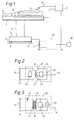
- Figure 1
- illustrates the system in use with electrosurgery apparatus;
- Figure 2
- is a circuit diagram of one form of monitor; and
- Figure 3
- is a circuit diagram of an alternative form of monitor.
- With reference to Figure 1, the table includes a conventional
patient support platform 1 at the upper end of anadjustable column 2 which is mounted on abase 3. Thebase 3 stands on the floor 4 on four electrically-insulative feet 5, such as of rubber, or on insulating castors or wheels (not shown). The table is made mainly of metal and it is, therefore, electrically conductive but is isolated from earth by thefeet 5. In order to discharge static that may build up on the table, ahigh impedance resistor 6 is connected between earth and thebase 3 or some other part of the table. The impedance of theresistor 6 is 100KΩ such that current flow through it is limited to values that are safe to the patient in the event that a live conductor should come into contact with the patient or table. - The table may be used in conjunction with
electrosurgery equipment 10 forming a part of the system. This equipment comprises anelectrosurgery generator 11 that produces RF current to a hand-heldelectrode 12 which is applied by the surgeon to the patient's tissue so as to effect cutting, coagulation or a combination of cutting and coagulation. A return current path to thegenerator 11 is provided via a largearea plate electrode 13 attached to a part of the patient. - As so far described, the system is conventional.
- The system differs from previous systems, however, in that it includes a
monitor 20 connected across theresistor 6 which detects change in resistance between the table and earth; the monitor responds to such a change by providing an output online 14 to analarm unit 15, and, or alternatively, to theelectrosurgery generator 11. Thealarm unit 15 provides a visual or audible alarm, or both, to alert the user that isolation of the table has been compromised. The output provided to theelectrosurgery generator 11 could be arranged to disable the generator and terminate supply of power. It is preferable that an alarm is also given since there are often other electrical equipment in the vicinity of the table, such as electrically-operated instruments, monitors, lights and the like which, if faulty, could lead to a live conductor coming into contact with the patient or table. - The
monitor 20 may take several different forms, two of which are illustrated in Figures 2 and 3 respectively. - With reference first to Figure 2, the
monitor 20 has acapacitor 21 the electrodes of which are connected to respective change-overswitches 22 and 23. Although illustrated as being mechanical devices, theswitches 22 and 23 would in practice be conventional electronic switches controlled by a switching unit 24. With theswitches 22 and 23 in the position illustrated, thecapacitor 21 is connected across abattery 25, or other dc voltage source, so that the capacitor is charged. When the position of theswitches 22 and 23 changes to that shown in broken lines, thecapacitor 21 is instead connected across theresistor 6. In this position, the charge on thecapacitor 21 is dissipated through theresistor 6. Themonitor 20 also includes a voltage measuring unit 26 connected across thecapacitor 21 which measures the rate of decay of charge from the capacitor when it is connected across theresistor 6. If there is an alternative path to earth in addition to theresistor 6, there will be a reduction in the time taken for the charge on the capacitor to decay to a set voltage. This reduction in decay time is detected by the unit 26 which provides an output online 14 to thealarm unit 15 and, or alternatively, to theelectrosurgery generator 11. Similarly, if theresistor 6 should fail open circuit, this would lead to an increase in the decay time which is also detected by the unit 26 and signalled to the user by an appropriate alarm. - Figure 3 shows an alternative monitor 20' which includes a
transformer 30 having asecondary winding 31 connected across theresistor 6 via an isolating capacitor 32. Theprimary winding 33 of thetransformer 30 is connected to asource 34 of high frequency voltage. Avoltage measuring unit 35 is connected across theprimary winding 33. If an alternative path to earth exists, apart from theresistor 6, the secondary winding will be short circuited, thereby causing the voltage on the primary winding to reduce. Thevoltage measuring unit 35 detects any such change in voltage on the primary and provides an output online 14 accordingly to thealarm unit 15 and, or alternatively, to theelectrosurgery generator 11. - The
resistor 6 andmonitor 20 may, for example, be incorporated within thebase 3 of the table or they may be connected to the table by a cable. - It will be appreciated that various other forms of monitor could be used which are capable of responding to change in resistance between the table and earth.
Claims (7)
- A system including a patient support table which is normally electrically-isolated from earth except for a high impedance static discharge resistor (6) connected in series between the table and earth, characterised in that the system includes a monitor (20, 20') connected to permanently monitor the resistance during patient use across the resistor (6), and that the monitor (20, 20') is responsive to change in resistance between the table and earth and provides an output in accordance therewith.
- A system according to Claim 1, characterised in that the monitor (20) includes a capacitor (21), a voltage source (25) for charging the capacitor (21), a switch (22, 23) for periodically connecting the capacitor (21) across the resistor (6) and a unit (26) for detecting the decay rate of the capacitor (21) through the resistor (6), and characterised in that the detecting unit (26) is responsive to a change in the decay rate and provides an output in accordance therewith.
- A system according to Claim 1, characterised in that the monitor (20') includes a transformer (30), that the primary winding (31) of the transformer (30) is connected to a source of alternating voltage (34) and the secondary winding (33) is connected across the resistor (6), and characterised in that the monitor (20') includes a unit (35) for detecting change in voltage across the primary winding (31) indicative of change in resistance between the table and earth and for providing an output in accordance therewith.
- A system according to Claim 1 or 2 including an alarm unit (15), and characterised in that the output is provided to the alarm unit (15) to provide an audible or visual warning.
- A system according to any one of the preceding claims, including an electrosurgery unit (10), and characterised in that the output is provided to the electrosurgery unit (10) to disable the electrosurgery unit.
- A system according to any one of the preceding claims, characterised in that the monitor unit (20, 20') is incorporated in the table.
- A system according to any one of Claims 1 to 5, characterised in that the monitor unit (20, 20') is connected to the table by a cable.
Applications Claiming Priority (2)
| Application Number | Priority Date | Filing Date | Title |
|---|---|---|---|
| GB919125280AGB9125280D0 (en) | 1991-11-28 | 1991-11-28 | Patient support tables and monitors |
| GB9125280 | 1991-11-28 |
Publications (2)
| Publication Number | Publication Date |
|---|---|
| EP0544415A1 EP0544415A1 (en) | 1993-06-02 |
| EP0544415B1true EP0544415B1 (en) | 1995-03-08 |
Family
ID=10705358
Family Applications (1)
| Application Number | Title | Priority Date | Filing Date |
|---|---|---|---|
| EP92310023AExpired - LifetimeEP0544415B1 (en) | 1991-11-28 | 1992-11-02 | Patient support tables and monitors |
Country Status (8)
| Country | Link |
|---|---|
| US (1) | US5390382A (en) |
| EP (1) | EP0544415B1 (en) |
| AU (1) | AU655510B2 (en) |
| DE (1) | DE69201632T2 (en) |
| ES (1) | ES2069384T3 (en) |
| GB (2) | GB9125280D0 (en) |
| NZ (1) | NZ245001A (en) |
| ZA (1) | ZA929088B (en) |
Families Citing this family (32)
| Publication number | Priority date | Publication date | Assignee | Title |
|---|---|---|---|---|
| US5481194A (en)* | 1994-06-10 | 1996-01-02 | Westinghouse Electric Corp. | Fault detection circuit for sensing leakage currents between power source and chassis |
| US5664270A (en)* | 1994-07-19 | 1997-09-09 | Kinetic Concepts, Inc. | Patient interface system |
| US5966763A (en)* | 1996-08-02 | 1999-10-19 | Hill-Rom, Inc. | Surface pad system for a surgical table |
| US6772850B1 (en)* | 2000-01-21 | 2004-08-10 | Stryker Corporation | Power assisted wheeled carriage |
| AU2002303942B2 (en)* | 2001-06-01 | 2006-06-22 | Covidien Ag | Return pad cable connector |
| US6855158B2 (en) | 2001-09-11 | 2005-02-15 | Hill-Rom Services, Inc. | Thermo-regulating patient support structure |
| US6752224B2 (en)* | 2002-02-28 | 2004-06-22 | Stryker Corporation | Wheeled carriage having a powered auxiliary wheel, auxiliary wheel overtravel, and an auxiliary wheel drive and control system |
| US6860881B2 (en)* | 2002-09-25 | 2005-03-01 | Sherwood Services Ag | Multiple RF return pad contact detection system |
| CA2542849C (en)* | 2003-10-23 | 2013-08-20 | Sherwood Services Ag | Redundant temperature monitoring in electrosurgical systems for safety mitigation |
| US20060079872A1 (en)* | 2004-10-08 | 2006-04-13 | Eggleston Jeffrey L | Devices for detecting heating under a patient return electrode |
| CA2541037A1 (en) | 2005-03-31 | 2006-09-30 | Sherwood Services Ag | Temperature regulating patient return electrode and return electrode monitoring system |
| US20070049914A1 (en)* | 2005-09-01 | 2007-03-01 | Sherwood Services Ag | Return electrode pad with conductive element grid and method |
| US7412736B2 (en)* | 2005-09-13 | 2008-08-19 | Midmark Corporation | Conjoined electrical cords for an examination table |
| US7736359B2 (en)* | 2006-01-12 | 2010-06-15 | Covidien Ag | RF return pad current detection system |
| US20070244478A1 (en)* | 2006-04-18 | 2007-10-18 | Sherwood Services Ag | System and method for reducing patient return electrode current concentrations |
| US20080009846A1 (en)* | 2006-07-06 | 2008-01-10 | Sherwood Services Ag | Electrosurgical return electrode with an involuted edge |
| US7637907B2 (en)* | 2006-09-19 | 2009-12-29 | Covidien Ag | System and method for return electrode monitoring |
| US7927329B2 (en)* | 2006-09-28 | 2011-04-19 | Covidien Ag | Temperature sensing return electrode pad |
| US7722603B2 (en)* | 2006-09-28 | 2010-05-25 | Covidien Ag | Smart return electrode pad |
| US8777940B2 (en)* | 2007-04-03 | 2014-07-15 | Covidien Lp | System and method for providing even heat distribution and cooling return pads |
| US20080249524A1 (en)* | 2007-04-03 | 2008-10-09 | Tyco Healthcare Group Lp | System and method for providing even heat distribution and cooling return pads |
| US8021360B2 (en)* | 2007-04-03 | 2011-09-20 | Tyco Healthcare Group Lp | System and method for providing even heat distribution and cooling return pads |
| US8080007B2 (en)* | 2007-05-07 | 2011-12-20 | Tyco Healthcare Group Lp | Capacitive electrosurgical return pad with contact quality monitoring |
| US8388612B2 (en)* | 2007-05-11 | 2013-03-05 | Covidien Lp | Temperature monitoring return electrode |
| US8231614B2 (en)* | 2007-05-11 | 2012-07-31 | Tyco Healthcare Group Lp | Temperature monitoring return electrode |
| US8100898B2 (en) | 2007-08-01 | 2012-01-24 | Tyco Healthcare Group Lp | System and method for return electrode monitoring |
| US8801703B2 (en) | 2007-08-01 | 2014-08-12 | Covidien Lp | System and method for return electrode monitoring |
| US9987072B2 (en)* | 2008-03-17 | 2018-06-05 | Covidien Lp | System and method for detecting a fault in a capacitive return electrode for use in electrosurgery |
| US8442738B2 (en)* | 2009-10-12 | 2013-05-14 | Stryker Corporation | Speed control for patient handling device |
| US20120195078A1 (en)* | 2011-02-01 | 2012-08-02 | Michael Levin | Prevention of safety hazards due to leakage current |
| EP2511998B1 (en)* | 2011-04-13 | 2015-08-26 | AEG Power Solutions GmbH | Assembly for earth connection surveillance in an alternating current circuit and power supply assembly with such an earth connection surveillance |
| CN106063755B (en)* | 2016-05-25 | 2017-12-01 | 衢州市联橙环保科技有限公司 | an operating bed |
Family Cites Families (13)
| Publication number | Priority date | Publication date | Assignee | Title |
|---|---|---|---|---|
| US3590322A (en)* | 1970-02-12 | 1971-06-29 | Sci Systems Inc | Medical instrumentation system |
| US3845355A (en)* | 1973-05-04 | 1974-10-29 | Borg Warner | Fault protection circuit for an adjustable motorized hospital bed |
| GB1480736A (en)* | 1973-08-23 | 1977-07-20 | Matburn Ltd | Electrodiathermy apparatus |
| US3978465A (en)* | 1974-10-25 | 1976-08-31 | Esb Incorporated | Line isolation monitor |
| US4231372A (en)* | 1974-11-04 | 1980-11-04 | Valleylab, Inc. | Safety monitoring circuit for electrosurgical unit |
| US4200104A (en)* | 1977-11-17 | 1980-04-29 | Valleylab, Inc. | Contact area measurement apparatus for use in electrosurgery |
| US4200105A (en)* | 1978-05-26 | 1980-04-29 | Dentsply Research & Development Corp. | Electrosurgical safety circuit |
| US4558309A (en)* | 1983-06-27 | 1985-12-10 | The Simco Company, Inc. | Ground tether continuity monitor |
| US4580186A (en)* | 1983-07-15 | 1986-04-01 | Parker Douglas F | Grounding and ground fault detection circuits |
| JPS6078359A (en)* | 1983-10-05 | 1985-05-04 | Hitachi Ltd | Static leonard device |
| SE450675B (en)* | 1984-11-19 | 1987-07-13 | Klaus Winter | DEVICE FOR MONITORING OF THE NETWORK PARAMETERS DIMENSION, OSYMMETRIGRADE AND SCREW RECONCILIATION IN IMPEDANCED POWER NETWORK |
| AT384358B (en)* | 1985-04-29 | 1987-11-10 | Hill Thomas | DEVICE FOR DETECTING HIGH-FREQUENCY ERROR CURRENTS |
| US4716487A (en)* | 1986-05-05 | 1987-12-29 | Automeg, Inc. | Apparatus for monitoring motor winding leakage |
- 1991
- 1991-11-28GBGB919125280Apatent/GB9125280D0/enactivePending
- 1992
- 1992-11-02EPEP92310023Apatent/EP0544415B1/ennot_activeExpired - Lifetime
- 1992-11-02ESES92310023Tpatent/ES2069384T3/ennot_activeExpired - Lifetime
- 1992-11-02DEDE69201632Tpatent/DE69201632T2/ennot_activeExpired - Fee Related
- 1992-11-03GBGB9223007Apatent/GB2262005B/ennot_activeExpired - Fee Related
- 1992-11-03NZNZ245001Apatent/NZ245001A/enunknown
- 1992-11-04USUS07/971,465patent/US5390382A/ennot_activeExpired - Fee Related
- 1992-11-05AUAU28147/92Apatent/AU655510B2/ennot_activeCeased
- 1992-11-24ZAZA929088Apatent/ZA929088B/enunknown
Also Published As
| Publication number | Publication date |
|---|---|
| GB2262005B (en) | 1995-09-27 |
| DE69201632T2 (en) | 1995-07-06 |
| GB9125280D0 (en) | 1992-01-29 |
| DE69201632D1 (en) | 1995-04-13 |
| NZ245001A (en) | 1995-11-27 |
| GB2262005A (en) | 1993-06-02 |
| GB9223007D0 (en) | 1992-12-16 |
| ZA929088B (en) | 1993-05-19 |
| EP0544415A1 (en) | 1993-06-02 |
| AU655510B2 (en) | 1994-12-22 |
| ES2069384T3 (en) | 1995-05-01 |
| US5390382A (en) | 1995-02-21 |
| AU2814792A (en) | 1993-06-03 |
Similar Documents
| Publication | Publication Date | Title |
|---|---|---|
| EP0544415B1 (en) | Patient support tables and monitors | |
| US3913583A (en) | Control circuit for electrosurgical units | |
| US5540722A (en) | Switch apparatus and method for switching between multiple electrodes for diagnostic and therapeutic procedures | |
| EP0617925B1 (en) | Electrosurgery unit with electrode safety monitor | |
| CA1196967A (en) | Electrosurgical generator safety apparatus | |
| CA2499855C (en) | Multiple rf return pad contact detection system | |
| US3683923A (en) | Electrosurgery safety circuit | |
| US4200104A (en) | Contact area measurement apparatus for use in electrosurgery | |
| US4122854A (en) | Electrosurgical apparatus | |
| US4051855A (en) | Electrosurgical unit | |
| CA1079811A (en) | Electrosurgical device | |
| US4200105A (en) | Electrosurgical safety circuit | |
| US4331149A (en) | Electrosurgical device | |
| US3905373A (en) | Electrosurgical device | |
| EP0533360B1 (en) | Electrosurgery apparatus | |
| JPS62155841A (en) | Method and apparatus for monitoring neutral electrode for high frequency surgical apparatus | |
| CA2112817A1 (en) | Electrosurgical Apparatus for Laparoscopic and Like Procedures | |
| GB2374532A (en) | Electrosurgery apparatus monitoring impedance of split-plate return electrode | |
| US4114622A (en) | Electrosurgical device | |
| US3987796A (en) | Electrosurgical device | |
| CN103930212A (en) | Improvements in and related to laparoscopic instruments | |
| JP3580895B2 (en) | Induction cautery equipment | |
| Tooley | Electrical safety, defibrillation and diathermy | |
| KERR et al. | Electrical design and safety in the operating room and intensive care unit | |
| KR20050001030A (en) | Control device for an electric leakage of medical facilities |
Legal Events
| Date | Code | Title | Description |
|---|---|---|---|
| PUAI | Public reference made under article 153(3) epc to a published international application that has entered the european phase | Free format text:ORIGINAL CODE: 0009012 | |
| AK | Designated contracting states | Kind code of ref document:A1 Designated state(s):DE ES FR IE IT | |
| 17P | Request for examination filed | Effective date:19931019 | |
| 17Q | First examination report despatched | Effective date:19940728 | |
| GRAA | (expected) grant | Free format text:ORIGINAL CODE: 0009210 | |
| AK | Designated contracting states | Kind code of ref document:B1 Designated state(s):DE ES FR IE IT | |
| REF | Corresponds to: | Ref document number:69201632 Country of ref document:DE Date of ref document:19950413 | |
| REG | Reference to a national code | Ref country code:ES Ref legal event code:FG2A Ref document number:2069384 Country of ref document:ES Kind code of ref document:T3 | |
| ITF | It: translation for a ep patent filed | ||
| ET | Fr: translation filed | ||
| PGFP | Annual fee paid to national office [announced via postgrant information from national office to epo] | Ref country code:IE Payment date:19951017 Year of fee payment:4 | |
| PGFP | Annual fee paid to national office [announced via postgrant information from national office to epo] | Ref country code:ES Payment date:19951107 Year of fee payment:4 | |
| PGFP | Annual fee paid to national office [announced via postgrant information from national office to epo] | Ref country code:FR Payment date:19951129 Year of fee payment:4 | |
| PGFP | Annual fee paid to national office [announced via postgrant information from national office to epo] | Ref country code:DE Payment date:19960104 Year of fee payment:4 | |
| PLBE | No opposition filed within time limit | Free format text:ORIGINAL CODE: 0009261 | |
| 26N | No opposition filed | ||
| PG25 | Lapsed in a contracting state [announced via postgrant information from national office to epo] | Ref country code:IE Free format text:LAPSE BECAUSE OF NON-PAYMENT OF DUE FEES Effective date:19961102 | |
| PG25 | Lapsed in a contracting state [announced via postgrant information from national office to epo] | Ref country code:ES Free format text:LAPSE BECAUSE OF NON-PAYMENT OF DUE FEES Effective date:19961103 | |
| PG25 | Lapsed in a contracting state [announced via postgrant information from national office to epo] | Ref country code:FR Effective date:19970731 | |
| PG25 | Lapsed in a contracting state [announced via postgrant information from national office to epo] | Ref country code:DE Effective date:19970801 | |
| REG | Reference to a national code | Ref country code:FR Ref legal event code:ST | |
| REG | Reference to a national code | Ref country code:ES Ref legal event code:FD2A Effective date:19971213 | |
| PG25 | Lapsed in a contracting state [announced via postgrant information from national office to epo] | Ref country code:IT Free format text:LAPSE BECAUSE OF NON-PAYMENT OF DUE FEES;WARNING: LAPSES OF ITALIAN PATENTS WITH EFFECTIVE DATE BEFORE 2007 MAY HAVE OCCURRED AT ANY TIME BEFORE 2007. THE CORRECT EFFECTIVE DATE MAY BE DIFFERENT FROM THE ONE RECORDED. Effective date:20051102 |