EP0544403B1 - Vehicle navigation system - Google Patents
Vehicle navigation systemDownload PDFInfo
- Publication number
- EP0544403B1 EP0544403B1EP92309692AEP92309692AEP0544403B1EP 0544403 B1EP0544403 B1EP 0544403B1EP 92309692 AEP92309692 AEP 92309692AEP 92309692 AEP92309692 AEP 92309692AEP 0544403 B1EP0544403 B1EP 0544403B1
- Authority
- EP
- European Patent Office
- Prior art keywords
- vehicle
- sensor
- coefficient
- distance
- gps
- Prior art date
- Legal status (The legal status is an assumption and is not a legal conclusion. Google has not performed a legal analysis and makes no representation as to the accuracy of the status listed.)
- Expired - Lifetime
Links
Images

Classifications
- G—PHYSICS
- G01—MEASURING; TESTING
- G01C—MEASURING DISTANCES, LEVELS OR BEARINGS; SURVEYING; NAVIGATION; GYROSCOPIC INSTRUMENTS; PHOTOGRAMMETRY OR VIDEOGRAMMETRY
- G01C21/00—Navigation; Navigational instruments not provided for in groups G01C1/00 - G01C19/00
- G01C21/26—Navigation; Navigational instruments not provided for in groups G01C1/00 - G01C19/00 specially adapted for navigation in a road network
- G01C21/28—Navigation; Navigational instruments not provided for in groups G01C1/00 - G01C19/00 specially adapted for navigation in a road network with correlation of data from several navigational instruments
Definitions
- the present inventionrelates to a navigation system installed in a vehicle which displays the position and direction of the vehicle, map information of an area around the vehicle, etc., and, more particularly, to a navigation system which calculates coefficients of devices, such as a velocity sensor, for obtaining a travel distance based on the rotation of the tires of the vehicle.
- a known vehicle navigation systemobtains travel distances and rotational angles by using a velocity sensor or a distance sensor and an angle sensor and, based on the travel distances and rotational angles, discovers the position and direction of the vehicle. If necessary, the vehicle's positional data is corrected by comparing a travel path of the vehicle with map data. Further, if a GPS (Global Positioning System), which measures the absolute position of a vehicle, is available, the position measured by the navigation system can be corrected so as to equal the position measured by the GPS (GPS position).
- GPSGlobal Positioning System
- This known navigation systemobtains a travel distance by the velocity sensor detecting pulses or the like outputted in accordance with the rotation of the tires of the vehicle and by the number of the detected pulses multiplied by a coefficient which is used for converting a number of pulses to a distance, that is, a coefficient of the velocity sensor.
- the GPScannot always fully function; for example, a sufficient number of satellites are usually not available for measuring positions in the vicinity of tall buildings or high mountains. Therefore, in the above-described known navigation apparatus, in order to perform sufficiently precise positioning even in such areas where GPS is not usable, the positioning precision of dead reckoning performed by using a velocity sensor and an angular velocity sensor must be substantially high. In order to maintain high positioning precision of the dead reckoning system, a user must correct the coefficient of the velocity sensor if the size of tires change because of, e.g., age deterioration or pressure changes in the tires, or because the tires are changed. However, a change in this coefficient greatly affects the positioning precision, and it is not easy for the user to perform such a delicate correction.
- a methodhas been developed in which the velocity sensor coefficient is automatically corrected by using map data, more specifically, by comparing the length of a travel path of a vehicle which is obtained on the basis of various positions of the vehicle calculated by the navigation system with the corresponding distance separately obtained from the road data of the map data.
- Fig. 1illustrates this method. While the length of a travel path 503 between two corners 501 and 502 is being compared with the distance 504 therebetween obtained from road data, the velocity sensor coefficient is automatically corrected so that the travel path length 503 becomes equal to the distance 504 based on road data.
- Fig. 2if there are two streets 602, 603 which are close to each other in the vicinity of a corner 601 and have similar appearances and directions, one street may be mistaken for the other. If the street 603 is mistaken for the street 602 on a map when the velocity sensor coefficient is going to be automatically corrected, the navigation system calculates such a velocity sensor coefficient that a travel path length 604 becomes equal to the distance 605 to the street 603 instead of the distance to the street 602, thus increasing any error in the velocity sensor coefficient. Therefore, the positioning precision deteriorates.
- Japanese Patent Unexamined Publication No. 2-212714discloses a method in which a ratio is obtained between an integrated travel distance of a travelling object which is obtained by the GPS navigation method using satellites and another integrated travel distance which is obtained by an independent navigation method using a distance sensor or the like, and the output of a distance sensor is corrected by using this ratio as a correction parameter.
- United States patent specification No. US 4713767 and Patent Abstracts of Japan publication No. JP 2107985each disclose a vehicle navigation system including a first sensor for detecting a velocity of a vehicle; a second sensor for detecting a direction of the vehicle; estimated position calculating means for calculating estimated positions of the vehicle on the basis of outputs of said first and second sensors; means for obtaining positional data of the vehicle from an outside of the vehicle; and sensor coefficient calculating means for calculating a coefficient of said first sensor on the basis of a ratio between a distance between two positions of the vehicle obtained by said positional data means, and a distance of travel of the vehicle calculated on the basis of signals outputted by said first sensor during a period between when one of said two positions of the vehicle is obtained and when the other position is obtained.
- an object of the present inventionis to provide a vehicle navigation system which obtains precise velocity sensor coefficients which are used to multiply the outputs of a velocity sensor and thus achieves high precision in position measurement.
- the present inventionis characterised over the known art in that the system includes linear travel detecting means for detecting linear travel of the vehicle on the basis of a travel path of the vehicle obtained on the basis of a plurality of the estimated positions and the coefficient of the first sensor is calculated for a linear travel section of the vehicle as detected by said linear travel detecting means.
- the velocity sensor coefficientis automatically corrected if the size of the tires changes due to age deterioration or pressure changes in the tires, or because the tires are changed. Further, the system of this invention can perform such correction without using map data, thus eliminating errors caused by the use of the map data.
- a velocity sensor 101detects the velocity of a vehicle in which the navigation system is installed. More specifically, the velocity sensor 101 outputs a pulse every time the vehicle has travelled a predetermined distance.
- An angular velocity detector 102detects angular velocity of the vehicle during travelling of the vehicle. Instead of the angular sensor 102, other types of direction sensors, such as a geomagnetic sensor, may be used.
- Japanese Patent Unexamined Publication No. 63-262518 and othersdisclose a system in which a velocity sensor and a geomagnetic sensor are used to estimate the position of a vehicle.
- a GPS receiver 103receives radio waves from a plurality of GPS satellites and outputs data on the position where the radio waves are received (referred to as the "GPS position” hereinafter) .
- GPS positionSuch GPS receivers are described in detail in Nippon Musen Gihou, No. 24, pp. 16 to 23, 1986.
- An estimated position and direction calculating means 104calculates current position and direction of the vehicle (current position and direction of the vehicle thus obtained are referred to as an "estimated position” and an “estimated direction” hereinafter) on the basis of signals outputted by the velocity sensor 101 and the angular velocity sensor 102.
- a linear travel detecting means 105detects linear travel of the vehicle, on the basis of the estimated position and direction.
- a velocity sensor coefficient calculating means 106calculates a velocity sensor coefficient on the basis of a ratio between a distance between two positions measured by the GPS (Global Positioning System) during the linear travel of the vehicle and a distance (a linear travel distance) obtained on the basis of output values which the velocity sensor 101 generates between when the first position of the two GPS positions is measured and when the second GPS position is measured.
- GPSGlobal Positioning System
- a vehicle 201travels on a road 202.
- the navigation systemcorrects the estimated position 204 so that it coincides with a position 205 on which the vehicle is supposed to travel.
- the state of linear travellingis usually detected by discovering that changes in the travel direction of the vehicle remain within a predetermined angle over a predetermined distance or greater. This is an easy method for a vehicle navigation system, and the present invention uses this method.
- a point 206is a first GPS position measured by the GPS during linear travel of the vehicle.
- a point 207is an estimated position of the vehicle calculated at a time when the first GPS position 206 is measured.
- the navigation systemstarts integration output values of the velocity sensor 101, that is, integration of values obtained by multiplying the output values of the velocity sensor 101, i.e., the number of pulses, by a coefficient.
- the navigation systemcorrects the estimated position 209 so that it coincides with a position 210 on which the vehicle is supposed to travel. Because a vehicle must travel a predetermined distance or greater in order to calculate a velocity sensor coefficient, the estimated position 209 before correction is stored as well and renewed as an estimated position which is used to calculate a velocity sensor coefficient.
- K pls (n)K pls (n-1) x (1 - ⁇ + ⁇ x d1 gps /d1 pls ) where:
- this embodimentusing the GPS instead of map data, automatically calculates a new velocity sensor coefficient by, for example, obtaining a ratio of a distance between two GPS 25 positions in a linear travel section to a distance obtained by using the velocity sensor when the vehicle has linearly travelled in a period between measurements of the two GPS positions, or multiplying such a ratio by the previous velocity sensor coefficient. Therefore, a user of the navigation system does not need to correct velocity sensor coefficients. Further, the velocity sensor coefficient is automatically corrected without an error caused by misreading of map data.
- a “GPS position” as described in the above embodimentis not necessarily positional data directly outputted by the GPS receiver.
- a “GPS position”may be a central position of a predetermined number of plural positional data obtained in a period of a predetermined length (such as a mean position (centroid) of all these positions, or a position which provides the minimum sum of squares of distances therefrom to all the individual positions).
- positional datamay be obtained from stations which transmit positional data, such as sign posts, as described in Japanese Patent Unexamined Publication No. 62-279720 and Japanese Utility Model Unexamined Publication No. 2-98533, providing substantially the same effects.
- the navigation system of the present inventionautomatically corrects the velocity sensor coefficient which changes due to age deterioration or the like.
- the systemeliminates the need for a user to correct the velocity coefficient and, further, eliminates errors caused by correction of the velocity sensor coefficient on the basis of map data, thus achieving high-precision position measurement.
Landscapes
- Engineering & Computer Science (AREA)
- Radar, Positioning & Navigation (AREA)
- Remote Sensing (AREA)
- Automation & Control Theory (AREA)
- Physics & Mathematics (AREA)
- General Physics & Mathematics (AREA)
- Navigation (AREA)
- Position Fixing By Use Of Radio Waves (AREA)
Description
- The present invention relates to a navigation system installed in a vehicle which displays the position and direction of the vehicle, map information of an area around the vehicle, etc., and, more particularly, to a navigation system which calculates coefficients of devices, such as a velocity sensor, for obtaining a travel distance based on the rotation of the tires of the vehicle.
- A known vehicle navigation system obtains travel distances and rotational angles by using a velocity sensor or a distance sensor and an angle sensor and, based on the travel distances and rotational angles, discovers the position and direction of the vehicle. If necessary, the vehicle's positional data is corrected by comparing a travel path of the vehicle with map data. Further, if a GPS (Global Positioning System), which measures the absolute position of a vehicle, is available, the position measured by the navigation system can be corrected so as to equal the position measured by the GPS (GPS position).
- This known navigation system obtains a travel distance by the velocity sensor detecting pulses or the like outputted in accordance with the rotation of the tires of the vehicle and by the number of the detected pulses multiplied by a coefficient which is used for converting a number of pulses to a distance, that is, a coefficient of the velocity sensor.
- The GPS cannot always fully function; for example, a sufficient number of satellites are usually not available for measuring positions in the vicinity of tall buildings or high mountains. Therefore, in the above-described known navigation apparatus, in order to perform sufficiently precise positioning even in such areas where GPS is not usable, the positioning precision of dead reckoning performed by using a velocity sensor and an angular velocity sensor must be substantially high. In order to maintain high positioning precision of the dead reckoning system, a user must correct the coefficient of the velocity sensor if the size of tires change because of, e.g., age deterioration or pressure changes in the tires, or because the tires are changed. However, a change in this coefficient greatly affects the positioning precision, and it is not easy for the user to perform such a delicate correction.
- To avoid this problem, a method has been developed in which the velocity sensor coefficient is automatically corrected by using map data, more specifically, by comparing the length of a travel path of a vehicle which is obtained on the basis of various positions of the vehicle calculated by the navigation system with the corresponding distance separately obtained from the road data of the map data. Fig. 1 illustrates this method. While the length of a
travel path 503 between twocorners distance 504 therebetween obtained from road data, the velocity sensor coefficient is automatically corrected so that thetravel path length 503 becomes equal to thedistance 504 based on road data. - However, in this method, positioning precision sometimes deteriorates. As shown in Fig. 2, if there are two
streets corner 601 and have similar appearances and directions, one street may be mistaken for the other. If thestreet 603 is mistaken for thestreet 602 on a map when the velocity sensor coefficient is going to be automatically corrected, the navigation system calculates such a velocity sensor coefficient that atravel path length 604 becomes equal to thedistance 605 to thestreet 603 instead of the distance to thestreet 602, thus increasing any error in the velocity sensor coefficient. Therefore, the positioning precision deteriorates. - Further, Japanese Patent Unexamined Publication No. 2-212714 discloses a method in which a ratio is obtained between an integrated travel distance of a travelling object which is obtained by the GPS navigation method using satellites and another integrated travel distance which is obtained by an independent navigation method using a distance sensor or the like, and the output of a distance sensor is corrected by using this ratio as a correction parameter.
- In this method, however, a travel distance obtained on the basis of outputs of the sensor is likely to deviate from the actual travel distance if the distance between positioning points is great and the travel path has curves. Thus, the method will likely fail to precisely correct sensor outputs.
- United States patent specification No. US 4713767 and Patent Abstracts of Japan publication No. JP 2107985 each disclose a vehicle navigation system including a first sensor for detecting a velocity of a vehicle; a second sensor for detecting a direction of the vehicle; estimated position calculating means for calculating estimated positions of the vehicle on the basis of outputs of said first and second sensors; means for obtaining positional data of the vehicle from an outside of the vehicle; and sensor coefficient calculating means for calculating a coefficient of said first sensor on the basis of a ratio between a distance between two positions of the vehicle obtained by said positional data means, and a distance of travel of the vehicle calculated on the basis of signals outputted by said first sensor during a period between when one of said two positions of the vehicle is obtained and when the other position is obtained.
- Each of these systems, however, encounter the problem associated with the method of Japanese Patent Unexamined Publication No. 2-212714.
- The present invention is intended to solve the above-described problems of the known art. Accordingly, an object of the present invention is to provide a vehicle navigation system which obtains precise velocity sensor coefficients which are used to multiply the outputs of a velocity sensor and thus achieves high precision in position measurement.
- The present invention is characterised over the known art in that the system includes linear travel detecting means for detecting linear travel of the vehicle on the basis of a travel path of the vehicle obtained on the basis of a plurality of the estimated positions and the coefficient of the first sensor is calculated for a linear travel section of the vehicle as detected by said linear travel detecting means.
- Therefore, according to the present invention, the velocity sensor coefficient is automatically corrected if the size of the tires changes due to age deterioration or pressure changes in the tires, or because the tires are changed. Further, the system of this invention can perform such correction without using map data, thus eliminating errors caused by the use of the map data.
- The foregoing and further features of the present invention will be more readily understood from the following description of a preferred embodiment, by way of example thereof, and with reference to the accompanying drawings, of which:-
- Fig. 1 illustrates the operation for calculating coefficients of a velocity sensor in a conventional navigation system;
- Fig. 2 illustrates problems of the operation illustrated in Fig. 1;
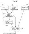
- Fig. 3 is a block diagram of a navigation system according to an embodiment of the present invention; and
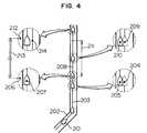
- Fig. 4 illustrates the operation of the navigation system illustrated in Fig. 3.
- A navigation system according to an embodiment of the present invention is illustrated in Fig. 3. In the figure, a
velocity sensor 101 detects the velocity of a vehicle in which the navigation system is installed. More specifically, thevelocity sensor 101 outputs a pulse every time the vehicle has travelled a predetermined distance. Anangular velocity detector 102 detects angular velocity of the vehicle during travelling of the vehicle. Instead of theangular sensor 102, other types of direction sensors, such as a geomagnetic sensor, may be used. Japanese Patent Unexamined Publication No. 63-262518 and others disclose a system in which a velocity sensor and a geomagnetic sensor are used to estimate the position of a vehicle. AGPS receiver 103 receives radio waves from a plurality of GPS satellites and outputs data on the position where the radio waves are received (referred to as the "GPS position" hereinafter) . Such GPS receivers are described in detail in Nippon Musen Gihou, No. 24, pp. 16 to 23, 1986. An estimated position and direction calculating means 104 calculates current position and direction of the vehicle (current position and direction of the vehicle thus obtained are referred to as an "estimated position" and an "estimated direction" hereinafter) on the basis of signals outputted by thevelocity sensor 101 and theangular velocity sensor 102. A linear travel detecting means 105 detects linear travel of the vehicle, on the basis of the estimated position and direction. A velocity sensor coefficient calculating means 106 calculates a velocity sensor coefficient on the basis of a ratio between a distance between two positions measured by the GPS (Global Positioning System) during the linear travel of the vehicle and a distance (a linear travel distance) obtained on the basis of output values which thevelocity sensor 101 generates between when the first position of the two GPS positions is measured and when the second GPS position is measured. - The operation of the navigation system according to the embodiment of the present invention will be described with reference to Fig. 4. In Fig. 4, a
vehicle 201 travels on aroad 202. At apoint 204, it is found that thevehicle 201 has linearly travelled a predetermined distance or longer on atravel path 203. The navigation system corrects the estimatedposition 204 so that it coincides with aposition 205 on which the vehicle is supposed to travel. The state of linear travelling is usually detected by discovering that changes in the travel direction of the vehicle remain within a predetermined angle over a predetermined distance or greater. This is an easy method for a vehicle navigation system, and the present invention uses this method. - A
point 206 is a first GPS position measured by the GPS during linear travel of the vehicle. Apoint 207 is an estimated position of the vehicle calculated at a time when thefirst GPS position 206 is measured. At thepoint 207, the navigation system starts integration output values of thevelocity sensor 101, that is, integration of values obtained by multiplying the output values of thevelocity sensor 101, i.e., the number of pulses, by a coefficient. Then, at apoint 209 where the linear travel detecting means 105 detects a linear travel of a predetermined distance or greater 208, the navigation system corrects the estimatedposition 209 so that it coincides with aposition 210 on which the vehicle is supposed to travel. Because a vehicle must travel a predetermined distance or greater in order to calculate a velocity sensor coefficient, the estimatedposition 209 before correction is stored as well and renewed as an estimated position which is used to calculate a velocity sensor coefficient. - Then, when the vehicle has linearly travelled a
predetermined distance 211 or greater and asecond GPS position 212 is measured, thedistance 213 between the twoGPS positions position 207 calculated when thefirst GPS position 206 is measured and an estimatedposition 214 calculated on a travel path which has not been corrected by the navigation system, when thesecond GPS position 212 is measured. Next, a value is obtained by dividing the distance between the GPS positions by the estimated linear travel distance and defined as a new velocity sensor coefficient (see Expression (1)).
- Kpls(n) is a new velocity sensor coefficient;
- d1gps is a distance between two GPS positions; and
- d1pls is a distance obtained using values outputted by the velocity sensor during a period between measurements of the two GPS positions.
- Instead of directly calculating a velocity sensor coefficient from a distance between GPS positions and an estimated travel distance, a new velocity sensor coefficient may be calculated by multiplying the ratio between these two distances by the previous velocity sensor coefficient as follows:

- kpls(n) is a new velocity sensor coefficient;
- kpls(n-1) is the previous velocity sensor coefficient;
- dgps is a distance between two GPS positions; and
- d1gps is a distance obtained using values outputted by the velocity sensor during a period between measurements of the two GPS positions.
- Further, instead of immediately shifting to a new velocity sensor coefficient, the previous velocity sensor coefficient may be gradually converged to the target value so as to smooth changes of the coefficient due to rapid acceleration and deceleration of the vehicle, as follows:

- Kpls(n) is a new velocity sensor coefficient;
- Kpls(n-1) is the previous velocity sensor coefficient;
- d1gps is a distance between two GPS positions;
- d1gps is a distance obtained using values outputted by the velocity sensor during a period between measurements of the two GPS positions; and
- α is a coefficient which determines the rate of convergence to the target value (0 ≤ α ≤ 1).
- As described above, this embodiment, using the GPS instead of map data, automatically calculates a new velocity sensor coefficient by, for example, obtaining a ratio of a distance between two GPS 25 positions in a linear travel section to a distance obtained by using the velocity sensor when the vehicle has linearly travelled in a period between measurements of the two GPS positions, or multiplying such a ratio by the previous velocity sensor coefficient. Therefore, a user of the navigation system does not need to correct velocity sensor coefficients. Further, the velocity sensor coefficient is automatically corrected without an error caused by misreading of map data.
- A "GPS position" as described in the above embodiment is not necessarily positional data directly outputted by the GPS receiver. For example, for the purpose of stabilisation, a "GPS position" may be a central position of a predetermined number of plural positional data obtained in a period of a predetermined length (such as a mean position (centroid) of all these positions, or a position which provides the minimum sum of squares of distances therefrom to all the individual positions).
- Though the above embodiment obtains positional data from the outside by using the GPS, positional data may be obtained from stations which transmit positional data, such as sign posts, as described in Japanese Patent Unexamined Publication No. 62-279720 and Japanese Utility Model Unexamined Publication No. 2-98533, providing substantially the same effects.
- As described above in connection with the embodiments, the navigation system of the present invention automatically corrects the velocity sensor coefficient which changes due to age deterioration or the like. Thus, the system eliminates the need for a user to correct the velocity coefficient and, further, eliminates errors caused by correction of the velocity sensor coefficient on the basis of map data, thus achieving high-precision position measurement.


Claims (6)
- A vehicle navigation system comprising: a first sensor (101) for detecting a velocity of a vehicle (201); a second sensor (102) for detecting a direction of the vehicle (201); estimated position calculating means (104) for calculating estimated positions of the vehicle (201) on the basis of outputs of said first and second sensors (101, 102); means (103) for obtaining positional data of the vehicle (201) from an outside of the vehicle (201); and sensor coefficient calculating means (106) for calculating a coefficient of said first sensor (101) on the basis of a ratio between a distance between two positions of the vehicle obtained by said positional data means (103), and a distance of travel of the vehicle calculated on the basis of signals outputted by said first sensor (101) during a period between when one of said two positions of the vehicle is obtained and when the other position is obtained, characterised in that the system includes linear travel detecting means (105) for detecting linear travel of the vehicle (201) on the basis of a travel path of the vehicle (201) obtained on the basis of a plurality of the estimated positions and the coefficient of the first sensor (101) is calculated for a linear travel section of the vehicle (201) as detected by said linear travel detecting means (105).
- A vehicle navigation system as claimed in claim 1, characterised in that said means (103) for obtaining positional data of the vehicle (201) is a GPS (Global Positioning System) receiver.
- A vehicle navigation system as claimed in claim 1 or claim 2, characterised in that the linear travel detecting means (105) detects a state of linear travelling by detecting that changes in the travel direction of the vehicle (201) remain within a predetermined angle over a predetermined distance.
- A vehicle navigation system as claimed in any one of claims 1 to 3, characterised in that the sensor coefficient calculating means (106) will not calculate a first sensor coefficient unless the vehicle (201) has travelled a predetermined distance.
- A vehicle navigation system as claimed in any preceding claim, characterised in that the sensor coefficient calculating means (106) calculates a new first sensor coefficient from the ratio between the distance between the two positions of the vehicle (201) obtained by the positional data means (103) and a distance of travel of the vehicle (201) calculated from outputs of the first sensor (101) multiplied by a previous first sensor coefficient.
- A vehicle navigation system as claimed in any one of claims 1 to 4, characterised in that a new first sensor coefficient is obtained by converging previous first sensor coefficients to a target value in accordance with the following relationship:
 Kpls(n) is a new first sensor coefficient;Kpls(n-1) is the previous first sensor coefficient;d1gps is a distance between two GPS positions;d1gps is a distance obtained using values outputted by the first sensor (101) during a period between measurements of the two GPS positions; andα is a coefficient which determines the rate of convergence to the target value (0 ≤ α ≤ 1).

Applications Claiming Priority (2)
| Application Number | Priority Date | Filing Date | Title |
|---|---|---|---|
| JP279220/91 | 1991-10-25 | ||
| JP27922091 | 1991-10-25 |
Publications (2)
| Publication Number | Publication Date |
|---|---|
| EP0544403A1 EP0544403A1 (en) | 1993-06-02 |
| EP0544403B1true EP0544403B1 (en) | 1996-09-25 |
Family
ID=17608104
Family Applications (1)
| Application Number | Title | Priority Date | Filing Date |
|---|---|---|---|
| EP92309692AExpired - LifetimeEP0544403B1 (en) | 1991-10-25 | 1992-10-22 | Vehicle navigation system |
Country Status (4)
| Country | Link |
|---|---|
| US (2) | US5483457A (en) |
| EP (1) | EP0544403B1 (en) |
| CA (1) | CA2081185C (en) |
| DE (1) | DE69214098T2 (en) |
Families Citing this family (73)
| Publication number | Priority date | Publication date | Assignee | Title |
|---|---|---|---|---|
| JP3378360B2 (en)* | 1994-06-30 | 2003-02-17 | 松下電器産業株式会社 | Speed sensor coefficient calculation device |
| EP0699894B1 (en)* | 1994-09-01 | 2002-03-27 | Aisin Aw Co., Ltd. | Navigation system |
| JP3483962B2 (en)* | 1994-12-05 | 2004-01-06 | 株式会社ザナヴィ・インフォマティクス | Navigation equipment |
| JP3578511B2 (en)* | 1995-04-21 | 2004-10-20 | 株式会社ザナヴィ・インフォマティクス | Current position calculation device |
| US5898390A (en)* | 1995-09-14 | 1999-04-27 | Zexel Corporation | Method and apparatus for calibration of a distance sensor in a vehicle navigation system |
| US5862511A (en)* | 1995-12-28 | 1999-01-19 | Magellan Dis, Inc. | Vehicle navigation system and method |
| US6029111A (en)* | 1995-12-28 | 2000-02-22 | Magellan Dis, Inc. | Vehicle navigation system and method using GPS velocities |
| US5991692A (en)* | 1995-12-28 | 1999-11-23 | Magellan Dis, Inc. | Zero motion detection system for improved vehicle navigation system |
| AT405769B (en)* | 1996-01-18 | 1999-11-25 | Elin Ebg Traction Gmbh | Method of determining and presetting the desired speed value in rail bound vehicles |
| JPH1062194A (en)* | 1996-08-13 | 1998-03-06 | Sony Corp | Sensitivity-correction method, navigation equipment and vehicle |
| US5987371A (en)* | 1996-12-04 | 1999-11-16 | Caterpillar Inc. | Apparatus and method for determining the position of a point on a work implement attached to and movable relative to a mobile machine |
| US6011461A (en)* | 1996-12-13 | 2000-01-04 | Eaton Corporation | Detection of truck speed sensor failure using GPS |
| US6308134B1 (en) | 1996-12-27 | 2001-10-23 | Magellan Dis, Inc. | Vehicle navigation system and method using multiple axes accelerometer |
| US5828585A (en)* | 1997-01-17 | 1998-10-27 | Delco Electronics Corporation | Vehicle speed signal calibration |
| US6230100B1 (en)* | 1997-01-31 | 2001-05-08 | Motorola, Inc. | Method and apparatus for differential scale factor calibration in differential odometry systems integrated with GPS |
| ID25826A (en)* | 1998-01-23 | 2000-11-09 | Toyota Motor Co Ltd | COST PROCESSING SYSTEM, COST CALCULATION SYSTEM AND COST PROCESSING CARD |
| US6360165B1 (en) | 1999-10-21 | 2002-03-19 | Visteon Technologies, Llc | Method and apparatus for improving dead reckoning distance calculation in vehicle navigation system |
| US6282496B1 (en) | 1999-10-29 | 2001-08-28 | Visteon Technologies, Llc | Method and apparatus for inertial guidance for an automobile navigation system |
| US8060389B2 (en) | 2000-06-07 | 2011-11-15 | Apple Inc. | System and method for anonymous location based services |
| US6456234B1 (en) | 2000-06-07 | 2002-09-24 | William J. Johnson | System and method for proactive content delivery by situation location |
| US8073565B2 (en) | 2000-06-07 | 2011-12-06 | Apple Inc. | System and method for alerting a first mobile data processing system nearby a second mobile data processing system |
| US6629031B2 (en)* | 2001-11-06 | 2003-09-30 | Volvo Trucks North America, Inc. | Vehicle tampering protection system |
| JP4295953B2 (en)* | 2002-04-26 | 2009-07-15 | パイオニア株式会社 | Distance coefficient learning device, method, program, recording medium for recording the program, movement status calculation device, and current position calculation device |
| US6831599B2 (en)* | 2002-08-26 | 2004-12-14 | Honeywell International Inc. | Remote velocity sensor slaved to an integrated GPS/INS |
| US20050107946A1 (en)* | 2003-11-13 | 2005-05-19 | Takanori Shimizu | Vehicle navigation apparatus |
| US7251493B2 (en)* | 2004-02-13 | 2007-07-31 | Sony Ericsson Mobile Communications Ab | Mobile terminals and methods for determining a location based on acceleration information |
| KR100609958B1 (en)* | 2004-07-29 | 2006-08-08 | 엘지전자 주식회사 | Self-tuning method of vehicle speed pulse coefficient |
| US7353034B2 (en) | 2005-04-04 | 2008-04-01 | X One, Inc. | Location sharing and tracking using mobile phones or other wireless devices |
| KR100631527B1 (en)* | 2005-06-23 | 2006-10-09 | 엘지전자 주식회사 | Apparatus and Method for Upgrading Operation Software of Embedded System |
| US7953526B2 (en)* | 2006-01-18 | 2011-05-31 | I-Guide Robotics, Inc. | Robotic vehicle controller |
| US8239083B2 (en) | 2006-01-18 | 2012-08-07 | I-Guide Robotics, Inc. | Robotic vehicle controller |
| US8774825B2 (en) | 2007-06-28 | 2014-07-08 | Apple Inc. | Integration of map services with user applications in a mobile device |
| US8385946B2 (en) | 2007-06-28 | 2013-02-26 | Apple Inc. | Disfavored route progressions or locations |
| US9109904B2 (en) | 2007-06-28 | 2015-08-18 | Apple Inc. | Integration of map services and user applications in a mobile device |
| US8108144B2 (en) | 2007-06-28 | 2012-01-31 | Apple Inc. | Location based tracking |
| US8175802B2 (en) | 2007-06-28 | 2012-05-08 | Apple Inc. | Adaptive route guidance based on preferences |
| US8311526B2 (en) | 2007-06-28 | 2012-11-13 | Apple Inc. | Location-based categorical information services |
| US9066199B2 (en) | 2007-06-28 | 2015-06-23 | Apple Inc. | Location-aware mobile device |
| US8332402B2 (en) | 2007-06-28 | 2012-12-11 | Apple Inc. | Location based media items |
| US8275352B2 (en) | 2007-06-28 | 2012-09-25 | Apple Inc. | Location-based emergency information |
| US8180379B2 (en) | 2007-06-28 | 2012-05-15 | Apple Inc. | Synchronizing mobile and vehicle devices |
| US8290513B2 (en) | 2007-06-28 | 2012-10-16 | Apple Inc. | Location-based services |
| US8463238B2 (en) | 2007-06-28 | 2013-06-11 | Apple Inc. | Mobile device base station |
| US8204684B2 (en) | 2007-06-28 | 2012-06-19 | Apple Inc. | Adaptive mobile device navigation |
| US8762056B2 (en) | 2007-06-28 | 2014-06-24 | Apple Inc. | Route reference |
| US20090254274A1 (en)* | 2007-07-27 | 2009-10-08 | Kulik Victor | Navigation system for providing celestial and terrestrial information |
| US8127246B2 (en) | 2007-10-01 | 2012-02-28 | Apple Inc. | Varying user interface element based on movement |
| US8977294B2 (en) | 2007-10-10 | 2015-03-10 | Apple Inc. | Securely locating a device |
| US8467804B2 (en)* | 2007-10-16 | 2013-06-18 | Sony Corporation | Mobile terminals and methods for regulating power-on/off of a GPS positioning circuit |
| DE102007058193A1 (en)* | 2007-12-04 | 2009-06-10 | Continental Teves Ag & Co. Ohg | Method for calibrating a wheel speed detection system |
| US8355862B2 (en) | 2008-01-06 | 2013-01-15 | Apple Inc. | Graphical user interface for presenting location information |
| US8452529B2 (en) | 2008-01-10 | 2013-05-28 | Apple Inc. | Adaptive navigation system for estimating travel times |
| US9250092B2 (en) | 2008-05-12 | 2016-02-02 | Apple Inc. | Map service with network-based query for search |
| US8644843B2 (en) | 2008-05-16 | 2014-02-04 | Apple Inc. | Location determination |
| US8369867B2 (en) | 2008-06-30 | 2013-02-05 | Apple Inc. | Location sharing |
| US8024013B2 (en)* | 2008-07-09 | 2011-09-20 | Sony Ericsson Mobile Communications Ab | Regulating power duty cycle of an RF transmitter/receiver responsive to distance moved |
| US8359643B2 (en) | 2008-09-18 | 2013-01-22 | Apple Inc. | Group formation using anonymous broadcast information |
| US8103404B2 (en)* | 2008-11-13 | 2012-01-24 | Ezurio Limited | System and method for odometer calibration |
| US8670748B2 (en) | 2009-05-01 | 2014-03-11 | Apple Inc. | Remotely locating and commanding a mobile device |
| US8666367B2 (en) | 2009-05-01 | 2014-03-04 | Apple Inc. | Remotely locating and commanding a mobile device |
| US8660530B2 (en) | 2009-05-01 | 2014-02-25 | Apple Inc. | Remotely receiving and communicating commands to a mobile device for execution by the mobile device |
| US8374785B2 (en)* | 2010-01-28 | 2013-02-12 | Eride, Inc. | Tightly coupled GPS and dead-reckoning vehicle navigation |
| GB2497087A (en)* | 2011-11-29 | 2013-06-05 | Nissan Motor Mfg Uk Ltd | Speedometer calibration |
| CN103884869A (en)* | 2012-12-19 | 2014-06-25 | 北京百度网讯科技有限公司 | Sensor deviation correction method and device |
| GB2513393B (en) | 2013-04-26 | 2016-02-03 | Jaguar Land Rover Ltd | Vehicle hitch assistance system |
| GB2513392B (en)* | 2013-04-26 | 2016-06-08 | Jaguar Land Rover Ltd | System for a towing vehicle |
| JP6324408B2 (en)* | 2013-11-29 | 2018-05-16 | クラリオン株式会社 | Distance coefficient learning apparatus, distance coefficient learning method, and current position calculation apparatus |
| US9309631B2 (en) | 2014-03-26 | 2016-04-12 | Caterpillar Trimble Control Technologies Llc | Enhanced control of road construction equipment |
| US9574320B2 (en)* | 2014-03-26 | 2017-02-21 | Trimble Navigation Limited | Blended position solutions |
| CN107107867B (en) | 2014-09-29 | 2019-04-12 | 莱尔德无线技术(上海)有限公司 | Telematics device and method of controlling ignition of a vehicle |
| FR3057347B1 (en)* | 2016-10-06 | 2021-05-28 | Univ Aix Marseille | SYSTEM FOR MEASURING THE DISTANCE OF AN OBSTACLE BY OPTICAL FLOW |
| US11079761B2 (en)* | 2018-12-12 | 2021-08-03 | Ford Global Technologies, Llc | Vehicle path processing |
| CN113112041A (en)* | 2021-04-22 | 2021-07-13 | 深圳市阳谷医疗系统有限公司 | Cloud computing medical system based on air purifier |
Family Cites Families (10)
| Publication number | Priority date | Publication date | Assignee | Title |
|---|---|---|---|---|
| CA1235782A (en)* | 1984-05-09 | 1988-04-26 | Kazuo Sato | Apparatus for calculating position of vehicle |
| JPS62279720A (en)* | 1986-05-28 | 1987-12-04 | Sumitomo Electric Ind Ltd | Map information receiving device |
| JPS6326518A (en)* | 1986-07-19 | 1988-02-04 | Tokyo Keiki Co Ltd | Road surface measuring instrument |
| JPS63262518A (en)* | 1987-04-21 | 1988-10-28 | Mazda Motor Corp | Navigation apparatus for vehicle |
| JPH0298533A (en)* | 1988-09-29 | 1990-04-10 | Hitachi Shonan Denshi Co Ltd | Method for attaching a marking member and apparatus for attaching a marking member |
| JPH02107985A (en)* | 1988-10-15 | 1990-04-19 | Matsushita Electric Works Ltd | Vehicle-mounted distance meter and speed meter |
| JPH02212714A (en)* | 1989-02-14 | 1990-08-23 | Mitsubishi Electric Corp | Mobile navigation device |
| JP2536190B2 (en)* | 1989-10-24 | 1996-09-18 | 三菱電機株式会社 | Navigation device for mobile |
| JPH049710A (en)* | 1990-04-27 | 1992-01-14 | Pioneer Electron Corp | Navigation apparatus for vehicle |
| JPH04238220A (en)* | 1991-01-23 | 1992-08-26 | Sumitomo Electric Ind Ltd | Vehicle azimuth correcting device |
- 1992
- 1992-10-20USUS07/963,751patent/US5483457A/ennot_activeExpired - Lifetime
- 1992-10-22CACA002081185Apatent/CA2081185C/ennot_activeExpired - Fee Related
- 1992-10-22DEDE69214098Tpatent/DE69214098T2/ennot_activeExpired - Lifetime
- 1992-10-22EPEP92309692Apatent/EP0544403B1/ennot_activeExpired - Lifetime
- 1995
- 1995-09-19USUS08/530,586patent/US5539647A/ennot_activeExpired - Fee Related
Also Published As
| Publication number | Publication date |
|---|---|
| DE69214098D1 (en) | 1996-10-31 |
| US5483457A (en) | 1996-01-09 |
| US5539647A (en) | 1996-07-23 |
| CA2081185C (en) | 1996-12-03 |
| EP0544403A1 (en) | 1993-06-02 |
| DE69214098T2 (en) | 1997-03-13 |
| CA2081185A1 (en) | 1993-04-26 |
Similar Documents
| Publication | Publication Date | Title |
|---|---|---|
| EP0544403B1 (en) | Vehicle navigation system | |
| US6574550B2 (en) | Navigation apparatus | |
| US7414575B2 (en) | Position calculating apparatus, position calculating method, and program | |
| EP0716289B1 (en) | Navigation system using dead reckoning combined with radio navigation | |
| US5337243A (en) | Vehicle orientation calculating device | |
| KR930005713B1 (en) | Navigation device for moving object | |
| EP0527558B1 (en) | GPS navigation system with local speed direction sensing and PDOP accuracy evaluation | |
| EP0537499B1 (en) | On-vehicle position computing apparatus | |
| US5210540A (en) | Global positioning system | |
| EP0523860B1 (en) | Vehicle position and azimuth computing system | |
| US5422639A (en) | Navigation equipment which determines current position dependent on difference between calculated value of self-contained navigation and measured value of radio navigation | |
| US6766247B2 (en) | Position determination method and navigation device | |
| US20040027278A1 (en) | Apparatus and method for locating user equipment using global positioning system and dead reckoning | |
| JP3402383B2 (en) | Vehicle current position detection device | |
| JP2004069536A (en) | Data verification device and method | |
| JP3278911B2 (en) | GPS navigation system for vehicles | |
| JP3404905B2 (en) | Vehicle navigation system | |
| JP3552267B2 (en) | Vehicle position detection device | |
| JPH07306056A (en) | Vehicle mileage detector | |
| JP3731686B2 (en) | Position calculation device | |
| JP2958020B2 (en) | Travel control device for mobile vehicles | |
| JP2786309B2 (en) | Vehicle position detection device | |
| JP2603766B2 (en) | Direction detection method and direction detection device | |
| JPH03291519A (en) | Navigation system for moving body | |
| JPS635211A (en) | Position measuring device for vehicle |
Legal Events
| Date | Code | Title | Description |
|---|---|---|---|
| PUAI | Public reference made under article 153(3) epc to a published international application that has entered the european phase | Free format text:ORIGINAL CODE: 0009012 | |
| AK | Designated contracting states | Kind code of ref document:A1 Designated state(s):DE GB | |
| 17P | Request for examination filed | Effective date:19930712 | |
| 17Q | First examination report despatched | Effective date:19941026 | |
| GRAH | Despatch of communication of intention to grant a patent | Free format text:ORIGINAL CODE: EPIDOS IGRA | |
| GRAH | Despatch of communication of intention to grant a patent | Free format text:ORIGINAL CODE: EPIDOS IGRA | |
| GRAA | (expected) grant | Free format text:ORIGINAL CODE: 0009210 | |
| AK | Designated contracting states | Kind code of ref document:B1 Designated state(s):DE GB | |
| REF | Corresponds to: | Ref document number:69214098 Country of ref document:DE Date of ref document:19961031 | |
| PLBE | No opposition filed within time limit | Free format text:ORIGINAL CODE: 0009261 | |
| 26N | No opposition filed | ||
| REG | Reference to a national code | Ref country code:GB Ref legal event code:IF02 | |
| REG | Reference to a national code | Ref country code:GB Ref legal event code:746 Effective date:20091215 | |
| PGFP | Annual fee paid to national office [announced via postgrant information from national office to epo] | Ref country code:DE Payment date:20091015 Year of fee payment:18 | |
| PGFP | Annual fee paid to national office [announced via postgrant information from national office to epo] | Ref country code:GB Payment date:20091021 Year of fee payment:18 | |
| GBPC | Gb: european patent ceased through non-payment of renewal fee | Effective date:20101022 | |
| REG | Reference to a national code | Ref country code:DE Ref legal event code:R119 Ref document number:69214098 Country of ref document:DE Effective date:20110502 | |
| PG25 | Lapsed in a contracting state [announced via postgrant information from national office to epo] | Ref country code:GB Free format text:LAPSE BECAUSE OF NON-PAYMENT OF DUE FEES Effective date:20101022 | |
| PG25 | Lapsed in a contracting state [announced via postgrant information from national office to epo] | Ref country code:DE Free format text:LAPSE BECAUSE OF NON-PAYMENT OF DUE FEES Effective date:20110502 |