EP0544141B1 - Container with lid made from plastic - Google Patents
Container with lid made from plasticDownload PDFInfo
- Publication number
- EP0544141B1 EP0544141B1EP92119177AEP92119177AEP0544141B1EP 0544141 B1EP0544141 B1EP 0544141B1EP 92119177 AEP92119177 AEP 92119177AEP 92119177 AEP92119177 AEP 92119177AEP 0544141 B1EP0544141 B1EP 0544141B1
- Authority
- EP
- European Patent Office
- Prior art keywords
- edge
- lid
- container
- locating part
- recessed grip
- Prior art date
- Legal status (The legal status is an assumption and is not a legal conclusion. Google has not performed a legal analysis and makes no representation as to the accuracy of the status listed.)
- Expired - Lifetime
Links
- 238000007789sealingMethods0.000claimsabstractdescription15
- 239000000463materialSubstances0.000claimsabstract2
- 230000004308accommodationEffects0.000claims1
- 235000011837pastiesNutrition0.000abstractdescription3
- 239000007788liquidSubstances0.000abstractdescription2
- 239000011344liquid materialSubstances0.000abstract1
- 239000003973paintSubstances0.000description7
- 238000005452bendingMethods0.000description1
- 239000000428dustSubstances0.000description1
- 238000012986modificationMethods0.000description1
- 230000004048modificationEffects0.000description1
- 230000035515penetrationEffects0.000description1
- 230000002093peripheral effectEffects0.000description1
Images


Classifications
- B—PERFORMING OPERATIONS; TRANSPORTING
- B65—CONVEYING; PACKING; STORING; HANDLING THIN OR FILAMENTARY MATERIAL
- B65D—CONTAINERS FOR STORAGE OR TRANSPORT OF ARTICLES OR MATERIALS, e.g. BAGS, BARRELS, BOTTLES, BOXES, CANS, CARTONS, CRATES, DRUMS, JARS, TANKS, HOPPERS, FORWARDING CONTAINERS; ACCESSORIES, CLOSURES, OR FITTINGS THEREFOR; PACKAGING ELEMENTS; PACKAGES
- B65D43/00—Lids or covers for rigid or semi-rigid containers
- B65D43/02—Removable lids or covers
- B65D43/0202—Removable lids or covers without integral tamper element
- B65D43/0214—Removable lids or covers without integral tamper element secured only by friction or gravity
- B65D43/0216—Removable lids or covers without integral tamper element secured only by friction or gravity inside a peripheral U-shaped channel in the mouth of the container
- B—PERFORMING OPERATIONS; TRANSPORTING
- B65—CONVEYING; PACKING; STORING; HANDLING THIN OR FILAMENTARY MATERIAL
- B65D—CONTAINERS FOR STORAGE OR TRANSPORT OF ARTICLES OR MATERIALS, e.g. BAGS, BARRELS, BOTTLES, BOXES, CANS, CARTONS, CRATES, DRUMS, JARS, TANKS, HOPPERS, FORWARDING CONTAINERS; ACCESSORIES, CLOSURES, OR FITTINGS THEREFOR; PACKAGING ELEMENTS; PACKAGES
- B65D25/00—Details of other kinds or types of rigid or semi-rigid containers
- B65D25/28—Handles
- B65D25/32—Bail handles, i.e. pivoted rigid handles of generally semi-circular shape with pivot points on two opposed sides or wall parts of the conainter
- B—PERFORMING OPERATIONS; TRANSPORTING
- B65—CONVEYING; PACKING; STORING; HANDLING THIN OR FILAMENTARY MATERIAL
- B65D—CONTAINERS FOR STORAGE OR TRANSPORT OF ARTICLES OR MATERIALS, e.g. BAGS, BARRELS, BOTTLES, BOXES, CANS, CARTONS, CRATES, DRUMS, JARS, TANKS, HOPPERS, FORWARDING CONTAINERS; ACCESSORIES, CLOSURES, OR FITTINGS THEREFOR; PACKAGING ELEMENTS; PACKAGES
- B65D2401/00—Tamper-indicating means
- B65D2401/10—Tearable part of the container
- B—PERFORMING OPERATIONS; TRANSPORTING
- B65—CONVEYING; PACKING; STORING; HANDLING THIN OR FILAMENTARY MATERIAL
- B65D—CONTAINERS FOR STORAGE OR TRANSPORT OF ARTICLES OR MATERIALS, e.g. BAGS, BARRELS, BOTTLES, BOXES, CANS, CARTONS, CRATES, DRUMS, JARS, TANKS, HOPPERS, FORWARDING CONTAINERS; ACCESSORIES, CLOSURES, OR FITTINGS THEREFOR; PACKAGING ELEMENTS; PACKAGES
- B65D2543/00—Lids or covers essentially for box-like containers
- B65D2543/00009—Details of lids or covers for rigid or semi-rigid containers
- B65D2543/00018—Overall construction of the lid
- B65D2543/00064—Shape of the outer periphery
- B65D2543/00074—Shape of the outer periphery curved
- B65D2543/00101—Shape of the outer periphery curved square-like or rectangular-like
- B—PERFORMING OPERATIONS; TRANSPORTING
- B65—CONVEYING; PACKING; STORING; HANDLING THIN OR FILAMENTARY MATERIAL
- B65D—CONTAINERS FOR STORAGE OR TRANSPORT OF ARTICLES OR MATERIALS, e.g. BAGS, BARRELS, BOTTLES, BOXES, CANS, CARTONS, CRATES, DRUMS, JARS, TANKS, HOPPERS, FORWARDING CONTAINERS; ACCESSORIES, CLOSURES, OR FITTINGS THEREFOR; PACKAGING ELEMENTS; PACKAGES
- B65D2543/00—Lids or covers essentially for box-like containers
- B65D2543/00009—Details of lids or covers for rigid or semi-rigid containers
- B65D2543/00018—Overall construction of the lid
- B65D2543/00064—Shape of the outer periphery
- B65D2543/0012—Shape of the outer periphery having straight sides, e.g. with curved corners
- B65D2543/00175—Shape of the outer periphery having straight sides, e.g. with curved corners four straight sides, e.g. trapezium or diamond
- B65D2543/00194—Shape of the outer periphery having straight sides, e.g. with curved corners four straight sides, e.g. trapezium or diamond square or rectangular
- B—PERFORMING OPERATIONS; TRANSPORTING
- B65—CONVEYING; PACKING; STORING; HANDLING THIN OR FILAMENTARY MATERIAL
- B65D—CONTAINERS FOR STORAGE OR TRANSPORT OF ARTICLES OR MATERIALS, e.g. BAGS, BARRELS, BOTTLES, BOXES, CANS, CARTONS, CRATES, DRUMS, JARS, TANKS, HOPPERS, FORWARDING CONTAINERS; ACCESSORIES, CLOSURES, OR FITTINGS THEREFOR; PACKAGING ELEMENTS; PACKAGES
- B65D2543/00—Lids or covers essentially for box-like containers
- B65D2543/00009—Details of lids or covers for rigid or semi-rigid containers
- B65D2543/00018—Overall construction of the lid
- B65D2543/00259—Materials used
- B65D2543/00296—Plastic
- B—PERFORMING OPERATIONS; TRANSPORTING
- B65—CONVEYING; PACKING; STORING; HANDLING THIN OR FILAMENTARY MATERIAL
- B65D—CONTAINERS FOR STORAGE OR TRANSPORT OF ARTICLES OR MATERIALS, e.g. BAGS, BARRELS, BOTTLES, BOXES, CANS, CARTONS, CRATES, DRUMS, JARS, TANKS, HOPPERS, FORWARDING CONTAINERS; ACCESSORIES, CLOSURES, OR FITTINGS THEREFOR; PACKAGING ELEMENTS; PACKAGES
- B65D2543/00—Lids or covers essentially for box-like containers
- B65D2543/00009—Details of lids or covers for rigid or semi-rigid containers
- B65D2543/00444—Contact between the container and the lid
- B65D2543/00453—Contact between the container and the lid in a peripheral U-shaped channel of the container
- B65D2543/00472—Skirt
- B—PERFORMING OPERATIONS; TRANSPORTING
- B65—CONVEYING; PACKING; STORING; HANDLING THIN OR FILAMENTARY MATERIAL
- B65D—CONTAINERS FOR STORAGE OR TRANSPORT OF ARTICLES OR MATERIALS, e.g. BAGS, BARRELS, BOTTLES, BOXES, CANS, CARTONS, CRATES, DRUMS, JARS, TANKS, HOPPERS, FORWARDING CONTAINERS; ACCESSORIES, CLOSURES, OR FITTINGS THEREFOR; PACKAGING ELEMENTS; PACKAGES
- B65D2543/00—Lids or covers essentially for box-like containers
- B65D2543/00009—Details of lids or covers for rigid or semi-rigid containers
- B65D2543/00444—Contact between the container and the lid
- B65D2543/00481—Contact between the container and the lid on the inside or the outside of the container
- B65D2543/0049—Contact between the container and the lid on the inside or the outside of the container on the inside, or a part turned to the inside of the mouth of the container
- B65D2543/00509—Cup
- B—PERFORMING OPERATIONS; TRANSPORTING
- B65—CONVEYING; PACKING; STORING; HANDLING THIN OR FILAMENTARY MATERIAL
- B65D—CONTAINERS FOR STORAGE OR TRANSPORT OF ARTICLES OR MATERIALS, e.g. BAGS, BARRELS, BOTTLES, BOXES, CANS, CARTONS, CRATES, DRUMS, JARS, TANKS, HOPPERS, FORWARDING CONTAINERS; ACCESSORIES, CLOSURES, OR FITTINGS THEREFOR; PACKAGING ELEMENTS; PACKAGES
- B65D2543/00—Lids or covers essentially for box-like containers
- B65D2543/00009—Details of lids or covers for rigid or semi-rigid containers
- B65D2543/00824—Means for facilitating removing of the closure
- B65D2543/00944—Located only on the container, e.g. recesses
Definitions
- the inventionrelates to a container with a lid made of plastic for receiving pourable goods, the wall of which has an upper sealing edge for the load-bearing and sealing reception of the lid, a receiving part surrounding the container in the upper part at a distance, which protrudes through a supporting edge projecting near the sealing edge is worn approximately in the middle and has two opposite tabs for receiving a carrying bracket, in which the receiving part is provided on the inside at the upper end with a non-continuous snap edge, behind which the cover engages when it is put on, and in which the upper edge of the receiving part, one Forming engagement recess, is pulled down in an arc.
- Such containers or buckets with lidsare known in various designs and are intended to store the filled goods securely, to protect them against unwanted escape of them as well as against the entry of dust, dirt or moisture, to be mechanically stable and to open without special tools and, if possible, also close tightly again.
- the lidcan be pulled down to the level of the contents.
- EP-A1-0 287 980discloses a plastic bucket with an associated snap-in lid, in which the bucket and the lid are designed at their edges so that the lid securely seals and snaps into place.
- the upper part of the bucket wallis surrounded by a cylindrical ring, on which diametrically opposed pockets are formed on the circumference of the bucket to accommodate a carrying handle. At these points, the ring is pulled down in an arc so that the cover which is locked between the ring and the bucket wall can be gripped and lifted off.
- EP-A1-0287 980is unsuitable for paint buckets, since when pouring paint, paint can run between the cylindrical ring and the bucket wall, so that reopening of the paint bucket after prior closure is made considerably more difficult by the dried paint.
- GB-PS 14 89 515Another solution is known from GB-PS 14 89 515, according to which a container with a lid made of plastic for receiving granular, powdery, pasty or liquid goods with a round cross-section is described.
- the Wall of the containerhas an upper sealing edge for the load-bearing and sealing reception of the cover and is provided in its upper part with a receiving part surrounding the sealing edge.
- the receiving partis supported by a circumferential supporting edge protruding near the sealing edge. Characterized in that the upper edge of the receiving part and the supporting edge is pulled down in an arc to the level of the lower edge of the receiving part, a type of engaging recess is formed in this area, which allows the retaining fold on the lid to be gripped under.
- the inventionhas for its object to provide a container with a lid of the type mentioned in such a way that the lid is easier to grasp when the container is closed and can be removed without special tools and in which the pouring out of pourable goods is facilitated and the penetration of these goods between the receiving part and the wall of the container is avoided.
- the objectis achieved in a container with a lid of the type mentioned in that the upper edge of the receiving part and the supporting edge in a region of greater curvature of the container circumference or at least between the tabs is pulled down in an arc to the level of the lower edge of the receiving part, so that in this area, the engagement trough is formed, which allows the retaining fold of the cover to reach under, and that the engagement trough is designed in the lower part as a spout which consists of the laterally lowered surfaces of the supporting edge and its lower, flat section.
- the lidcan be gripped and pulled off particularly easily in the engagement recess.
- the fact that the trough is designed as a spout, the emptying of the containeris also much easier and at the same time avoided that, for example, paint can run between the receiving part and the wall of the container. This prevents the lid from sticking after the container has only been partially emptied and closed again.
- the engagement troughis arranged in a corner of the container. If the invention is to be applied to a square bucket, the support bracket can be attached in the usual way to the center of the sides of the bucket regardless of the arrangement of the engagement recess.
- the engagement troughis covered by a tear-off panel which is connected to the pulled-down part of the supporting edge by a plurality of webs formed with predetermined breaking points.
- This panelwhich can be easily attached when the container is being manufactured, permits the container to be filled and closed for the first time. However, the container can only be opened after the cover has been removed, so that unauthorized opening can be easily determined.
- the container 1consists of a base 2 with an upwardly extending wall 3, at the end of which a sealing edge 4 for receiving a lid 5 is arranged.
- the container 1has a substantially rectangular cross section.
- the sealing edge 4is surrounded on the outside of the container 1 by a receiving part 6 arranged at a distance from it, which is supported approximately centrally in the middle by a peripheral supporting edge 7 protruding from the wall 3 near the sealing edge 4.
- a snap edge 8is formed on its side facing the wall 3, behind which the retaining fold 9 of the cover 5 engages when it is put on.
- the retaining fold 9simultaneously encloses the sealing edge 4 of the container 1.
- an opening trough 13is incorporated into one of the corners of the container 1 in order to open the cover 5 in such a way that both the upper edge of the receiving part 6 and the supporting edge 7 together up to the level of the lower edge of the receiving part 6 are pulled down.
- the retaining fold 9is freely visible in this area and can be easily grasped, and thus the cover 5 can be lifted off.
- This spout 14enables the container 1 to be emptied comfortably without, for example, paint running between the receiving part 6 and the outer wall of the container 1.
- Thisenables the container 1 to be partially emptied and closed again without the retaining fold 9 being able to stick in the U-shaped part formed by the receiving part 6, the supporting edge 7 and the outer wall of the container 1.
- a tear-off screen 15is arranged in front of the engagement trough 13.
- This diaphragm 15is connected to the pulled-down part of the supporting edge 7 by a plurality of webs 16 designed as predetermined breaking points. ( Figure 4, 6)
- the circumferential receiving part 6appears in this area as closed, so that it can be clearly seen that the container 1 has not yet been opened.
- the lidcan be opened particularly easily if the engagement trough 13 is arranged in one of the corners of the container.
- the inventioncan be used for round, square or oval containers without further modification.
- oval containersin which the support bracket 12 is usually suspended diametrically opposite in the area of the greatest curvature of the container wall, it is possible to arrange both the tabs 10 required for hanging the bracket and the engagement troughs 13 in the same place. It is also possible to mount the engagement recess 13 between the opposite tabs 10.
Landscapes
- Engineering & Computer Science (AREA)
- Mechanical Engineering (AREA)
- Closures For Containers (AREA)
- Table Devices Or Equipment (AREA)
- Devices For Use In Laboratory Experiments (AREA)
- Details Of Rigid Or Semi-Rigid Containers (AREA)
- Fertilizers (AREA)
- Packages (AREA)
Abstract
Description
Translated fromGermanDie Erfindung betrifft einen Behälter mit Deckel aus Kunststoff zur Aufnahme schüttfähiger Güter, dessen Wand einen oberen Dichtrand zur tragenden und dichtenden Aufnahme des Deckels aufweist, wobei ein Aufnahmeteil den Behälter im oberen Teil mit Abstand umgibt, welches durch eine in der Nähe des Dichtrandes hervorstehende Tragkante etwa mittig getragen wird und zwei gegenüberliegende Laschen zur Aufnahme eines Tragbügels besitzt, bei dem das Aufnahmeteil auf der Innenseite am oberen Ende mit einer nicht durchgehenden Schnappkante versehen ist, hinter die der Deckel beim Aufsetzen rastend greift, und bei dem die Oberkante des Aufnahmeteiles , eine Eingriffmulde bildend, bogenförmig heruntergezogen ist.The invention relates to a container with a lid made of plastic for receiving pourable goods, the wall of which has an upper sealing edge for the load-bearing and sealing reception of the lid, a receiving part surrounding the container in the upper part at a distance, which protrudes through a supporting edge projecting near the sealing edge is worn approximately in the middle and has two opposite tabs for receiving a carrying bracket, in which the receiving part is provided on the inside at the upper end with a non-continuous snap edge, behind which the cover engages when it is put on, and in which the upper edge of the receiving part, one Forming engagement recess, is pulled down in an arc.
Derartige Behälter oder Eimer mit Deckel sind in verschiedenen Ausführungen bekannt und sollen das eingefüllte Gut sicher aufbewahren, gegen ungewollten Austritt dieses Gutes ebenso wie gegen Eintritt von Staub, Schmutz oder Feuchtigkeit schützen, mechanisch stabil sein und sich ohne besondere Werkzeuge öffnen und möglichst auch wieder dicht verschließen lassen. Der Deckel kann zur besseren Stapelbarkeit bis auf Höhe des Füllgutes heruntergezogen sein.Such containers or buckets with lids are known in various designs and are intended to store the filled goods securely, to protect them against unwanted escape of them as well as against the entry of dust, dirt or moisture, to be mechanically stable and to open without special tools and, if possible, also close tightly again. For better stackability, the lid can be pulled down to the level of the contents.
So ist aus der EP-A1-0 287 980 ein Eimer aus Kunststoff mit einem zugehörigen einrastbaren Deckel bekannt, bei dem der Eimer und der Deckel an ihren Rändern so ausgebildet sind, daß der Deckel sicher abdichtet und einrastet. Die Eimerwand wird im oberen Teil von einem zylindrischen Ring umgeben, an dem am Eimerumfang einander diametral gegenüberstehende Taschen zur Aufnahme eines Tragebügels angeformt sind. An diesen Stellen ist der Ring bogenförmig heruntergezogen, so daß der zwischen dem Ring und der Eimerwand eingerastete Deckel erfaßt und abgehoben werden kann.For example, EP-A1-0 287 980 discloses a plastic bucket with an associated snap-in lid, in which the bucket and the lid are designed at their edges so that the lid securely seals and snaps into place. The upper part of the bucket wall is surrounded by a cylindrical ring, on which diametrically opposed pockets are formed on the circumference of the bucket to accommodate a carrying handle. At these points, the ring is pulled down in an arc so that the cover which is locked between the ring and the bucket wall can be gripped and lifted off.
Bei rechteckigen Behältern oder Eimern ist das Untergreifen und Abziehen des Deckels in der Mitte der Seiten schwierig bzw. nahezu unmöglich. Die Anordnung der Taschen mit dem an dieser Stelle heruntergezogenen Ring in den Ecken des Behälters ist unzweckmäßig, da diese Anordnung einerseits optisch wenig gefällig wirkt und andererseits der Tragbügel diagonal verlaufen müßte.With rectangular containers or buckets, reaching under and pulling off the lid in the middle of the sides is difficult or almost impossible. The arrangement of the pockets with the ring pulled down at this point in the corners of the container is unsuitable, since on the one hand this arrangement is not very pleasing to the eye and on the other hand the support bracket should run diagonally.
Darüber hinaus ist die in der EP-A1-0287 980 beschriebene Lösung für Farbeimer unzweckmäßig, da beim Ausgießen Farbe zwischen den zylindrischen Ring und die Eimerwand laufen kann, so daß ein erneutes Öffnen des Farbeimers nach vorherigem Verschließen durch die eingetrocknete Farbe erheblich erschwert wird.In addition, the solution described in EP-A1-0287 980 is unsuitable for paint buckets, since when pouring paint, paint can run between the cylindrical ring and the bucket wall, so that reopening of the paint bucket after prior closure is made considerably more difficult by the dried paint.
Aus der GB-PS 14 89 515 ist eine weitere Lösung bekannt, nach der ein Behälter mit Deckel aus Kunststoff zur Aufnahme körniger, pulverförmiger, pastenförmiger oder flüssiger Güter mit rundem Querschnitt beschrieben wird. Die Wand des Behälters weist dabei einen oberen Dichtrand zur tragenden und dichtenden Aufnahme des Deckels auf und ist in seinem oberen Teil mit einem den Dichtrand abstandsweise umgebenden Aufnahmeteil versehen. Das Aufnahmeteil wird von einer in der Nähe des Dichtrandes hervorstehenden umlaufenden Tragkante getragen. Dadurch, daß die Oberkante des Aufnahmeteiles und die Tragkante bis auf die Ebene der Unterkante des Aufnahmeteiles bogenförmig heruntergezogen ist, entsteht in diesem Bereich eine Art Eingriffmulde, die ein Untergreifen des Haltefalzes am Deckel ermöglicht.Another solution is known from GB-
Mit dieser Lösung werden aber die aufgezeigten Nachteile nicht beseitigt, insbesondere wird ein Verkleben von Deckel und Behälter nach dem Ausgießen nicht verhindert.With this solution, however, the disadvantages shown are not eliminated; in particular, the lid and container do not stick together after pouring.
Der Erfindung liegt die Aufgabe zugrunde, einen Behälter mit Deckel der eingangs genannten Art so auszubilden, daß sich der Deckel bei verschlossenem Behälter leichter ergreifen und ohne besonderes Werkzeug abnehmen läßt und bei dem das Ausgießen schüttfähiger Güter erleichtert wird sowie das Eindringen dieser Güter zwischen das Aufnahmeteil und die Wand des Behälters vermieden wird.The invention has for its object to provide a container with a lid of the type mentioned in such a way that the lid is easier to grasp when the container is closed and can be removed without special tools and in which the pouring out of pourable goods is facilitated and the penetration of these goods between the receiving part and the wall of the container is avoided.
Die Aufgabe wird bei einem Behälter mit Deckel der eingangs genannten Art dadurch gelöst, daß die Oberkante des Aufnahmeteiles und die Tragkante in einem Bereich stärkerer Krümmung des Behälterumfanges oder zumindest zwischen den Laschen gemeinsam bis auf die Ebene der Unterkante des Aufnahmeteiles bogenförmig heruntergezogen ist, so daß in diesem Bereich die Eingriffmulde gebildet wird, die ein Untergreifen des Haltefalzes des Deckels ermöglicht, und daß die Eingriffmulde im unteren Teil als Ausgießer gestaltet ist, der aus den seitlich abgesenkten Flächen der Tragkante und deren unterem ebenen Abschnitt besteht.The object is achieved in a container with a lid of the type mentioned in that the upper edge of the receiving part and the supporting edge in a region of greater curvature of the container circumference or at least between the tabs is pulled down in an arc to the level of the lower edge of the receiving part, so that in this area, the engagement trough is formed, which allows the retaining fold of the cover to reach under, and that the engagement trough is designed in the lower part as a spout which consists of the laterally lowered surfaces of the supporting edge and its lower, flat section.
Wenn ein Behälter dieser Art geöffnet und ganz oder teilweise entleert werden soll, so kann der Deckel in der Eingriffmulde besonders leicht erfaßt und abgezogen werden. Dadurch, daß die Eingriffmulde gleichzeitig als Ausgießer ausgeführt ist, wird das Entleeren des Behälters ebenfalls wesentlich erleichtert und gleichzeitig vermieden, daß beispielsweise Farbe zwischen das Aufnahmeteil und die Wand des Behälters laufen kann. Damit wird verhindert, daß der Deckel festkleben kann, nachdem der Behälter nur teilweise entleert und wieder verschlossen wurde.If a container of this type is to be opened and completely or partially emptied, the lid can be gripped and pulled off particularly easily in the engagement recess. The fact that the trough is designed as a spout, the emptying of the container is also much easier and at the same time avoided that, for example, paint can run between the receiving part and the wall of the container. This prevents the lid from sticking after the container has only been partially emptied and closed again.
In einer Fortbildung der Erfindung ist die Eingriffmulde in einer Ecke des Behälters angeordnet. Soll die Erfindung bei einem eckigen Eimer angewendet werden, so kann der Tragbügel auf übliche Weise unabhängig von der Anordnung der Eingriffmulde mittig an den Seiten des Eimers befestigt werden.In a development of the invention, the engagement trough is arranged in a corner of the container. If the invention is to be applied to a square bucket, the support bracket can be attached in the usual way to the center of the sides of the bucket regardless of the arrangement of the engagement recess.
In einer Weiterbildung der Erfindung ist weiterhin vorgesehen, daß die Eingriffmulde durch eine abreißbare Blende überdeckt ist, die durch mehrere mit Sollbruchstellen ausgebildete Stege mit dem heruntergezogenen Teil der Tragkante verbunden ist.In a further development of the invention it is further provided that the engagement trough is covered by a tear-off panel which is connected to the pulled-down part of the supporting edge by a plurality of webs formed with predetermined breaking points.
Diese beim Herstellen des Behälters auf einfache Weise anzubringende Blende gestattet das Befüllen und erstmalige Verschließen des Behälters. Ein Öffnen des Behälters ist aber nur nach dem vorherigen Entfernen der Blende möglich, so daß ein unbefugtes Öffnen leicht festzustellen ist.This panel, which can be easily attached when the container is being manufactured, permits the container to be filled and closed for the first time. However, the container can only be opened after the cover has been removed, so that unauthorized opening can be easily determined.
Die Erfindung wird nachstehend in Ausführungsbeispielen anhand der Zeichnung näher erläutert. Dabei zeigen:
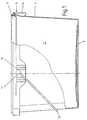
Figur 1- eine teilweise aufgebrochene Seitenansicht eines erfindungsgemäßen Behälters mit aufgesetztem Deckel,
Figur 2- eine Draufsicht auf den Behälter,
Figur 3- einen vergrößerten Teilschnitt längs der Linie III-III in
Figur 2, - Figur 4
- einen vergrößerten Teilschnitt längs der Linie IV-IV in
Figur 2, Figur 5- eine Detaildarstellung der Eingriffmulde, und
Figur 6- eine Detaildarstellung der Eingriffmulde mit einer davorgesetzten Blende.
- Figure 1
- a partially broken side view of a container according to the invention with a lid,
- Figure 2
- a plan view of the container,
- Figure 3
- 3 shows an enlarged partial section along the line III-III in FIG. 2,
- Figure 4
- 3 shows an enlarged partial section along the line IV-IV in FIG. 2,
- Figure 5
- a detailed representation of the trough, and
- Figure 6
- a detailed view of the intervention recess with a front panel.
Wie aus Figur 1 und 2 ersichtlich, besteht der Behälter 1 aus einem Boden 2 mit einer sich nach oben erstreckenden Wand 3, an deren Ende ein Dichtrand 4 zur Aufnahme eines Deckels 5 angeordnet ist. Entsprechend Figur 2 besitzt der Behälter 1 einen im wesentlichen rechteckigen Querschnitt. Der Dichtrand 4 wird auf der Außenseite des Behälters 1 von einem im Abstand zu diesem angeordneten Aufnahmeteil 6 umgeben, welches durch eine in der Nähe des Dichtrandes 4 aus der Wand 3 hervorstehende umlaufende Tragkante 7 etwa mittig getragen wird. Am oberen Ende des Aufnahmeteils 6 ist auf ihrer der Wand 3 zugewandten Seite eine Schnappkante 8 angeformt, hinter die der Haltefalz 9 des Deckels 5 beim Aufsetzen einrastet. Der Haltefalz 9 umschließt dabei gleichzeitig den Dichtrand 4 des Behälters 1. (Figur 3)As can be seen from FIGS. 1 and 2, the
Wie aus Fig. 1 ersichtlich, ist in der Mitte von zwei gegenüberliegenden Seitenflächen der Wand 1 die Unterkante des Aufnahmeteiles 6 bogenförmig, eine Lasche 10 bildend, heruntergezogen. In dieser Lasche 10 befindet sich ein Loch 11 zur Aufnahme des umgebogenen Endes eines Tragbügels 12.As can be seen from FIG. 1, in the middle of two opposite side surfaces of the
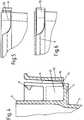
Wie aus den Figuren 4 bis 6 ersichtlich, ist zum Öffnen des Deckels 5 in einer der Ecken des Behälters 1 eine Eingriffmulde 13 derart eingearbeitet, daß sowohl die Oberkante des Aufnahmeteiles 6 als auch die Tragkante 7 gemeinsam bis auf die Ebene der Unterkante des Aufnahmeteiles 6 heruntergezogen sind. Dadurch wird in diesem Bereich der Haltefalz 9 frei sichtbar und kann leicht unterfaßt und somit der Deckel 5 abgehoben werden.As can be seen from FIGS. 4 to 6, an
Die seitlichen Flächen der abgesenkten Tragkante 7 und deren unterer ebener Abschnitt bilden gemeinsam einen Ausgießer 14. Dieser Ausgießer 14 ermöglicht ein bequemes Entleeren des Behälters 1, ohne daß beispielsweise Farbe zwischen das Aufnahmeteil 6 und die Außenwand des Behälters 1 laufen kann. Dadurch wird ermöglicht, daß der Behälter 1 teilweise entleert und wieder verschlossen werden kann, ohne daß der Haltefalz 9 in dem durch das Aufnahmeteil 6, die Tragkante 7 und die Außenwand des Behälters 1 gebildeten U-förmigen Teil festkleben kann.The lateral surfaces of the lowered supporting
Um ein unbefugtes Öffnen des Behälters 1 zu verhindern, bzw. nachträglich feststellen zu können, ist vor der Eingriffmulde 13 eine abreißbare Blende 15 angeordnet. Diese Blende 15 ist durch mehrere als Soll-Bruchstellen ausgebildete Stege 16 mit dem heruntergezogenen Teil der Tragkante 7 verbunden. (Figur 4, 6) Dadurch erscheint das umlaufende Aufnahmeteil 6 in diesem Bereich als geschlossen, so daß deutlich erkennbar ist, daß der Behälter 1 noch nicht geöffnet worden ist.In order to prevent unauthorized opening of the
Beim Abreißen der Blende 15 durch Abknicken und gegebenenfalls mehrmaliges Hin- und Herbiegen wird die Eingriffmulde 13 freigelegt, und der Deckel kann, wie bereits dargelegt, abgehoben werden.When the
Da die Eingriffmulde 13 unabhängig von der Lasche 10 angeordnet werden kann, ist bei einer Anordnung der Eingriffmulde 13 in einer der Ecken des Behälters ein besonders leichtes Öffnen des Deckels möglich.Since the
Die Erfindung kann ohne weitere Abänderung für runde, eckige oder ovale Behälter verwendet werden. Bei ovalen Behältern, bei denen der Tragbügel 12 üblicherweise diametral gegenüberliegend im Bereich der stärksten Krümmung der Behälterwand eingehängt ist, ist es möglich, sowohl die zum Einhängen des Bügels erforderlichen Laschen 10 als auch die Eingriffmulden 13 an der gleichen Stelle anzuordnen. Gleichfalls ist es möglich, die Eingriffmulde 13 zwischen den gegenüberliegenden Laschen 10 anzubringen.The invention can be used for round, square or oval containers without further modification. In the case of oval containers, in which the
Claims (3)
- Plastic container (1) with lid (5) for holding materials capable of being poured, the wall (3) of which has a top sealing edge (4) for the load-bearing and sealing accommodation of the lid (5), a locating part (6) surrounding the container (1) in its upper section at a distance, said part being borne roughly centrally by a supporting edge (7) projecting in the vicinity of the sealing edge (5) and having two opposite tabs (10) to accommodate a carrying handle (12), and where the locating part (6) is provided with an intermittent snap-on edge (8) on the inside at the top, behind which the lid (5) engages when put into place, and where the top edge of the locating part (6) is drawn down in the form of an arc, forming a recessed grip (13),characterised in that the top edge of the locating part (6) and the supporting edge (7) are drawn down together to the level of the lower edge of the locating part (6) in the form of an arc in one region of stronger curvature of the container perimeter or at least between the tabs (10), in such a way that the recessed grip (13) is formed in this region which makes it possible to grasp below the retaining fold (9) of the lid (5) and in such a way that the lower part of the recessed grip (13) is designed as a pourer (14) consisting of the laterally lowered surfaces of the supporting edge (7) and its lower, plane section.
- Plastic container (1) with lid (5) as per Claim 1,characterised in that, in case of a rectangular container (1), the recessed grip (13) is located in one corner.
- Plastic container (1) with lid (5) as per Claim 1 or 2,characterised in that the recessed grip (13) is covered by a tear-off strip (15) connected to the drawn-down part of the supporting edge (7) by several webs (16) designed with predetermined breaking points.
Applications Claiming Priority (2)
| Application Number | Priority Date | Filing Date | Title |
|---|---|---|---|
| DE4138879ADE4138879C1 (en) | 1991-11-27 | 1991-11-27 | |
| DE4138879 | 1991-11-27 |
Publications (2)
| Publication Number | Publication Date |
|---|---|
| EP0544141A1 EP0544141A1 (en) | 1993-06-02 |
| EP0544141B1true EP0544141B1 (en) | 1996-06-05 |
Family
ID=6445627
Family Applications (1)
| Application Number | Title | Priority Date | Filing Date |
|---|---|---|---|
| EP92119177AExpired - LifetimeEP0544141B1 (en) | 1991-11-27 | 1992-11-10 | Container with lid made from plastic |
Country Status (16)
| Country | Link |
|---|---|
| US (1) | US5303839A (en) |
| EP (1) | EP0544141B1 (en) |
| AT (1) | ATE138869T1 (en) |
| BG (1) | BG60203B2 (en) |
| CZ (1) | CZ279199B6 (en) |
| DE (2) | DE4138879C1 (en) |
| DK (1) | DK0544141T3 (en) |
| ES (1) | ES2089344T3 (en) |
| HU (2) | HU9203755D0 (en) |
| LT (1) | LT3069B (en) |
| LV (1) | LV10221B (en) |
| PL (1) | PL169717B1 (en) |
| RO (1) | RO109050B1 (en) |
| RU (1) | RU2044677C1 (en) |
| SI (1) | SI9200347B (en) |
| SK (1) | SK278521B6 (en) |
Families Citing this family (86)
| Publication number | Priority date | Publication date | Assignee | Title |
|---|---|---|---|---|
| US5507406A (en)* | 1994-04-26 | 1996-04-16 | Belford Patrick, Inc. | Tamperproof/tamper evident container |
| GB2294034B (en) | 1994-10-13 | 1998-09-23 | Plastictecnic | Container |
| GB9504277D0 (en)* | 1995-03-03 | 1995-04-19 | Peerless Plastics Packaging | Lidded containers |
| US5695087A (en)* | 1995-04-28 | 1997-12-09 | Canada Post Corporation | Container with latching lid |
| US5758791A (en)* | 1996-08-05 | 1998-06-02 | Tenneco Packaging Inc. | Latching mechanism for a plastic container |
| DE19737900C2 (en)* | 1997-08-31 | 2002-12-05 | Spritzguswerk Kg Richard Rassb | Device for securing plastic containers closed by a closure element and method for identifying the device |
| US5875913A (en)* | 1997-09-25 | 1999-03-02 | Letica Corporation | Tamper evident pail and closure |
| US5996833A (en)* | 1997-11-05 | 1999-12-07 | Sonoco Development, Inc. | Tamper evident dust cover for a drum bung |
| US5873482A (en)* | 1997-12-19 | 1999-02-23 | Plastican, Inc. | Tamper-evident container closure |
| US5960979A (en)* | 1998-01-26 | 1999-10-05 | Van Den Brink B.V. | Plastic bucket with lid and sealing lip |
| DE19855361C2 (en) | 1998-12-01 | 2003-05-28 | Jokey Plastik Wipperfuerth | Plastic container with a lid |
| IT248765Y1 (en)* | 1999-04-30 | 2003-02-12 | Internova Snc Di Alessio Pietr | CONTAINER AND SIMILAR WITH SAFETY CLOSURE |
| DE20006094U1 (en) | 2000-04-01 | 2000-09-14 | Jokey Plastik Gummersbach GmbH, 51645 Gummersbach | Plastic container with snap-on lid |
| US7032756B2 (en) | 2000-04-11 | 2006-04-25 | Wylie Arun M | Container |
| FR2816598A1 (en)* | 2000-11-14 | 2002-05-17 | Estrada Maria Teresa Pla | Lid for plastic containers has peripheral folds defining annular cavity whose outer web has intermediate step defining two sections, container has outward folding rim comprising U-shaped peripheral housing |
| CA97024S (en) | 2001-02-08 | 2004-06-01 | Freudenberg Carl Kg | Bucket |
| MXPA03009605A (en)* | 2001-04-18 | 2004-05-05 | Nottingham Spirk Partners Llc | Improved container and lid assembly. |
| USD482973S1 (en) | 2001-08-14 | 2003-12-02 | Nsi Innovation Llc | Square paint container |
| USD482974S1 (en) | 2001-08-14 | 2003-12-02 | Nsi Innovation Llp | Round paint container |
| USD563228S1 (en) | 2001-08-14 | 2008-03-04 | The Sherwin-Williams Company | Container for coating materials |
| USD482975S1 (en) | 2001-08-14 | 2003-12-02 | Nsi Innovation Llc | Round paint container |
| GB0122044D0 (en)* | 2001-09-12 | 2001-10-31 | Huhtamaki Uk Ltd | Tamper-evident lid assembly |
| GB0122281D0 (en)* | 2001-09-14 | 2001-11-07 | Ici Plc | A container for roller-applied paint and its use in coating procedures for rough surfaces |
| ATE353831T1 (en)* | 2002-07-26 | 2007-03-15 | Jokey Plastik Wipperfuerth | POT-SHAPED VESSEL, ESPECIALLY BUCKET, WITH A LID |
| USD576840S1 (en) | 2002-10-22 | 2008-09-16 | Pactiv Corporation | Bowl |
| US20060159807A1 (en)* | 2002-10-22 | 2006-07-20 | Hayes Thomas J | Container assemblies with releasable locking feature |
| USD527584S1 (en) | 2002-10-22 | 2006-09-05 | Pactiv Corporation | Bowl |
| US20060000076A1 (en)* | 2002-10-22 | 2006-01-05 | Hayes Thomas J | Method of using a container assembly |
| USD552424S1 (en) | 2002-10-22 | 2007-10-09 | Pactiv Corporation | Container |
| USD514880S1 (en) | 2002-10-22 | 2006-02-14 | Pactiv Corporation | Container |
| US6886704B2 (en)* | 2002-10-22 | 2005-05-03 | Pactiv Corporation | Containers and container assemblies with releasable locking feature |
| US20050189350A1 (en)* | 2002-10-22 | 2005-09-01 | Pactiv Corporation | Container assemblies with releasable locking feature |
| USD525083S1 (en) | 2002-10-22 | 2006-07-18 | Pactiv Corporation | Container |
| USD546621S1 (en) | 2002-10-22 | 2007-07-17 | Pactiv Corporation | Ribs pattern for container |
| DE10304452C5 (en)* | 2002-11-15 | 2009-08-06 | Deutsche Amphibolin-Werke Von Robert Murjahn Stiftung & Co. Kg | Container for containing coating materials |
| US20080087669A2 (en) | 2006-07-10 | 2008-04-17 | Inline Plastics Corp. | Tamper-resistant container with tamper-evident feature and method of forming same |
| DE102004015181A1 (en)* | 2004-03-25 | 2005-10-13 | Putzmeister Ag | Material feed container for a slurry pump |
| PL1755904T3 (en)* | 2004-06-08 | 2015-08-31 | Akzo Nobel Coatings Int Bv | Coating combination including a buoyant contacting member |
| USD525832S1 (en) | 2004-06-18 | 2006-08-01 | Pactiv Corporation | Container |
| USD526163S1 (en) | 2004-06-18 | 2006-08-08 | Pactiv Corporation | Bowl |
| USD551911S1 (en) | 2004-06-18 | 2007-10-02 | Pactiv Corporation | Container |
| USD525487S1 (en) | 2004-06-18 | 2006-07-25 | Pactiv Corporation | Container |
| USD528867S1 (en) | 2004-06-18 | 2006-09-26 | Pactiv Corporation | Container |
| USD545134S1 (en) | 2004-06-18 | 2007-06-26 | Pactiv Corporation | Bowl |
| USD533031S1 (en) | 2004-06-18 | 2006-12-05 | Pactiv Corporation | Bowl |
| USD520303S1 (en) | 2004-06-18 | 2006-05-09 | Pactiv Corporation | Container |
| USD526853S1 (en) | 2004-07-28 | 2006-08-22 | Pactiv Corporation | Container |
| WO2007016030A1 (en)* | 2005-07-26 | 2007-02-08 | Pactiv Corporation | Container assemblies with releasable locking feature |
| US8528770B2 (en)* | 2005-09-15 | 2013-09-10 | Wells Enterprises, Inc. | Self-venting food container |
| US8343560B2 (en)* | 2005-09-30 | 2013-01-01 | Reynolds Consumer Products Inc. | Modular container assembly and merchandizing container display |
| US8360262B2 (en) | 2005-12-21 | 2013-01-29 | Pactiv Packaging Inc. | Integrated food packaging system having a cup, a container, and a cover |
| US8833589B2 (en) | 2005-12-21 | 2014-09-16 | Pactiv Packaging Inc. | Enhanced tamper evident bowl with blocked tab |
| USD559036S1 (en) | 2006-02-07 | 2008-01-08 | Pactiv Corporation | Set of ribs for container |
| GB0623325D0 (en)* | 2006-11-22 | 2007-01-03 | Plastic Can Company The Ltd | Method and apparatus for making a container with a handle |
| WO2008074876A1 (en)* | 2006-12-21 | 2008-06-26 | Chandela Limited | A container and container closure |
| US7938286B2 (en)* | 2007-02-13 | 2011-05-10 | Gateway Plastics, Inc. | Container system |
| US8083084B2 (en)* | 2007-09-06 | 2011-12-27 | Pwp Industries, Inc. | Invertible tray |
| US8286817B2 (en)* | 2007-10-18 | 2012-10-16 | Mccormick & Company, Incorporated | Tamper resistant container with locking rim |
| US20090120942A1 (en)* | 2007-11-10 | 2009-05-14 | Terry Vovan | Convenient food container |
| US8127961B2 (en)* | 2007-11-10 | 2012-03-06 | Pwp Industries | Double ribbed secure container |
| USD599203S1 (en) | 2008-03-03 | 2009-09-01 | Mccormick & Company, Incorporated | Tamper evident lid for container with a locking lid and rim |
| US8011566B2 (en)* | 2008-03-12 | 2011-09-06 | Huhtamaki, Inc. | Hinged lid for a food container with plastic lower ring |
| CA2679213A1 (en)* | 2008-09-19 | 2010-03-19 | Par-Pak Ltd. | Tamper evident container with frangible closure member |
| US20100102074A1 (en) | 2008-10-28 | 2010-04-29 | Par-Pak Ltd. | Tamper evident container with frangible hinge |
| US8146766B2 (en) | 2009-04-29 | 2012-04-03 | Pwp Industries | Enhanced secure container |
| MX2012008013A (en)* | 2010-01-11 | 2012-11-30 | Superfos As | Container. |
| DE202010010711U1 (en)* | 2010-07-27 | 2011-10-28 | Pöppelmann Holding GmbH & Co. KG | Plastic containers |
| US8667735B2 (en)* | 2010-08-30 | 2014-03-11 | Att Southern, Inc. | Molded planter with wide upper rim |
| USD678768S1 (en) | 2011-06-16 | 2013-03-26 | AGAM Innovations Ltd. | Sealable pourer |
| US8944297B2 (en) | 2010-10-08 | 2015-02-03 | AGAM Innovations Ltd. | Sealable pourer |
| US9714123B2 (en) | 2010-10-08 | 2017-07-25 | AGAM Innovations Ltd. | Dispensing closure |
| USD638704S1 (en) | 2010-12-10 | 2011-05-31 | Pactiv Corporation | Container lid |
| USD637489S1 (en) | 2010-12-10 | 2011-05-10 | Pactiv Corporation | Pull grip feature of a container lid |
| USD738213S1 (en) | 2014-02-18 | 2015-09-08 | AGAM Innovations Ltd. | Pourer |
| USD792766S1 (en) | 2014-05-15 | 2017-07-25 | AGAM Innovations Ltd. | Pourer |
| USD807170S1 (en) | 2015-07-28 | 2018-01-09 | Wells Enterprises, Inc. | Container |
| USD803676S1 (en) | 2015-07-29 | 2017-11-28 | Wells Enterprises, Inc. | Container lid |
| USD823644S1 (en) | 2016-06-06 | 2018-07-24 | Reynolds Consumer Products LLC | Plate |
| USD823645S1 (en) | 2016-06-06 | 2018-07-24 | Reynolds Consumer Products LLC | Plate |
| USD818319S1 (en) | 2016-08-17 | 2018-05-22 | Reynolds Consumer Products LLC | Plate |
| USD846398S1 (en) | 2016-09-19 | 2019-04-23 | Mccormick & Company, Incorporated | Container with three door lid |
| USD850912S1 (en) | 2016-09-19 | 2019-06-11 | Mccormick & Company, Incorporated | Three door container lid |
| USD845139S1 (en) | 2016-09-19 | 2019-04-09 | Mccormick & Company, Incorporated | Spice container |
| BR112019005220A2 (en) | 2016-09-19 | 2019-06-11 | Mccormick & Company, Incorporated | three-door lid and container that uses the same |
| DE102018112237A1 (en)* | 2018-05-22 | 2019-11-28 | Jokey Plastik Wipperfürth GmbH | Container with lid |
| RU208937U1 (en)* | 2021-09-15 | 2022-01-24 | Михаил Владимирович Высоцкий | Container with hinged lids |
Family Cites Families (8)
| Publication number | Priority date | Publication date | Assignee | Title |
|---|---|---|---|---|
| CA858334A (en)* | 1968-08-09 | 1970-12-15 | I. Macdonald James | Y-flanged containers and cover members therefor |
| GB1489515A (en)* | 1975-10-22 | 1977-10-19 | Andersson P | Container with a lid of plastics material |
| US4335827A (en)* | 1979-09-28 | 1982-06-22 | Lippy Can Company, Ltd. | Can or container and lid therefor |
| US4671423A (en)* | 1986-04-09 | 1987-06-09 | Gilbert Plastics, Inc. | Container and lid means which resist removal after emplacement |
| WO1988007962A1 (en)* | 1987-04-18 | 1988-10-20 | Jokey-Plastik Gmbh & Co. Kg | Plastic bucket and lid |
| NL8902303A (en)* | 1989-09-14 | 1990-07-02 | Brink Gereedschappenfab Bv V D | HOLDER WITH LID FROM PLASTIC MATERIAL. |
| US5027969A (en)* | 1990-07-03 | 1991-07-02 | Ipl Inc. | Closure and container combination |
| US5097977A (en)* | 1991-02-27 | 1992-03-24 | Roy Straub | Closure assembly for container |
- 1991
- 1991-11-27DEDE4138879Apatent/DE4138879C1/denot_activeExpired - Fee Related
- 1992
- 1992-11-10ESES92119177Tpatent/ES2089344T3/ennot_activeExpired - Lifetime
- 1992-11-10DKDK92119177.1Tpatent/DK0544141T3/enactive
- 1992-11-10ATAT92119177Tpatent/ATE138869T1/ennot_activeIP Right Cessation
- 1992-11-10EPEP92119177Apatent/EP0544141B1/ennot_activeExpired - Lifetime
- 1992-11-10DEDE59206485Tpatent/DE59206485D1/ennot_activeExpired - Fee Related
- 1992-11-17LTLTIP181Apatent/LT3069B/ennot_activeIP Right Cessation
- 1992-11-19SKSK3432-92Apatent/SK278521B6/enunknown
- 1992-11-19CZCS923432Apatent/CZ279199B6/ennot_activeIP Right Cessation
- 1992-11-25USUS07/982,296patent/US5303839A/ennot_activeExpired - Fee Related
- 1992-11-25PLPL92296733Apatent/PL169717B1/enunknown
- 1992-11-26BGBG097121Apatent/BG60203B2/enunknown
- 1992-11-26LVLVP-92-217Apatent/LV10221B/enunknown
- 1992-11-26RORO92-01472Apatent/RO109050B1/enunknown
- 1992-11-26RURU9292004538Apatent/RU2044677C1/enactive
- 1992-11-27HUHU9203755Apatent/HU9203755D0/enunknown
- 1992-11-27HUHU9203755Apatent/HU217516B/ennot_activeIP Right Cessation
- 1992-11-27SISI9200347Apatent/SI9200347B/enunknown
Also Published As
| Publication number | Publication date |
|---|---|
| HUT67567A (en) | 1995-04-28 |
| LV10221B (en) | 1995-04-20 |
| LTIP181A (en) | 1994-03-25 |
| RU2044677C1 (en) | 1995-09-27 |
| DE4138879C1 (en) | 1992-12-17 |
| SK278521B6 (en) | 1997-08-06 |
| PL296733A1 (en) | 1993-07-26 |
| SK343292A3 (en) | 1994-11-09 |
| ATE138869T1 (en) | 1996-06-15 |
| US5303839A (en) | 1994-04-19 |
| DE59206485D1 (en) | 1996-07-11 |
| EP0544141A1 (en) | 1993-06-02 |
| LT3069B (en) | 1994-10-25 |
| DK0544141T3 (en) | 1996-10-28 |
| HU217516B (en) | 2000-02-28 |
| ES2089344T3 (en) | 1996-10-01 |
| SI9200347A (en) | 1993-06-30 |
| PL169717B1 (en) | 1996-08-30 |
| BG60203B2 (en) | 1993-12-30 |
| LV10221A (en) | 1994-10-20 |
| HU9203755D0 (en) | 1993-03-29 |
| CZ279199B6 (en) | 1995-01-18 |
| SI9200347B (en) | 2001-04-30 |
| RO109050B1 (en) | 1994-11-30 |
| CZ343292A3 (en) | 1993-09-15 |
Similar Documents
| Publication | Publication Date | Title |
|---|---|---|
| EP0544141B1 (en) | Container with lid made from plastic | |
| EP0287980B1 (en) | Pail and cover made of plastic material | |
| DE3901517C2 (en) | ||
| EP0405322B1 (en) | Package made from single cardboard blank | |
| EP0274742B1 (en) | Plastic container | |
| DE29802048U1 (en) | Paint can | |
| DE8807593U1 (en) | Refill bag | |
| EP0632786B1 (en) | Stable container, in particular garbage container | |
| EP1058654A1 (en) | Plastic lid with plastic seal | |
| EP0004075B1 (en) | Dispensing lid for a container for pulverulent material | |
| CH683834A5 (en) | Metal packaging with sealable edge profile. | |
| EP0742692B1 (en) | Conveying trolley having a base plate and uprights | |
| EP0641676B1 (en) | Container, particularly for storing paint or similar material | |
| DE4106110C2 (en) | ||
| DE19644542C2 (en) | Device for completely emptying bottles | |
| DE60036824T2 (en) | VERSCHLUSSKAPPE | |
| DE8906937U1 (en) | Plastic container and snap-on lid | |
| DE19900491B4 (en) | packaging | |
| DE29601108U1 (en) | Pot-shaped, lockable container-lid arrangement | |
| CH683334A5 (en) | Portable transport and storage containers. | |
| DE29507685U1 (en) | Lid for closing a box to hold wet wipes | |
| DE9304081U1 (en) | Container with a snap-on cover | |
| EP0417331A1 (en) | Rail for coating materials | |
| DE7814845U1 (en) | Cup-like container with pull-out partition | |
| DE1941978U (en) | STACKABLE CONTAINER. |
Legal Events
| Date | Code | Title | Description |
|---|---|---|---|
| PUAI | Public reference made under article 153(3) epc to a published international application that has entered the european phase | Free format text:ORIGINAL CODE: 0009012 | |
| AK | Designated contracting states | Kind code of ref document:A1 Designated state(s):AT BE CH DE DK ES FR GB IT LI LU NL PT SE | |
| 17P | Request for examination filed | Effective date:19931104 | |
| 17Q | First examination report despatched | Effective date:19950503 | |
| GRAH | Despatch of communication of intention to grant a patent | Free format text:ORIGINAL CODE: EPIDOS IGRA | |
| GRAH | Despatch of communication of intention to grant a patent | Free format text:ORIGINAL CODE: EPIDOS IGRA | |
| GRAA | (expected) grant | Free format text:ORIGINAL CODE: 0009210 | |
| AK | Designated contracting states | Kind code of ref document:B1 Designated state(s):AT BE CH DE DK ES FR GB IT LI LU NL PT SE | |
| REF | Corresponds to: | Ref document number:138869 Country of ref document:AT Date of ref document:19960615 Kind code of ref document:T | |
| REF | Corresponds to: | Ref document number:59206485 Country of ref document:DE Date of ref document:19960711 | |
| REG | Reference to a national code | Ref country code:CH Ref legal event code:NV Representative=s name:KATZAROV S.A. | |
| ITF | It: translation for a ep patent filed | ||
| ET | Fr: translation filed | ||
| GBT | Gb: translation of ep patent filed (gb section 77(6)(a)/1977) | Effective date:19960806 | |
| REG | Reference to a national code | Ref country code:ES Ref legal event code:FG2A Ref document number:2089344 Country of ref document:ES Kind code of ref document:T3 | |
| REG | Reference to a national code | Ref country code:DK Ref legal event code:T3 | |
| SC4A | Pt: translation is available | Free format text:960806 AVAILABILITY OF NATIONAL TRANSLATION | |
| REG | Reference to a national code | Ref country code:ES Ref legal event code:FG2A Ref document number:2089344 Country of ref document:ES Kind code of ref document:T3 | |
| PLBE | No opposition filed within time limit | Free format text:ORIGINAL CODE: 0009261 | |
| STAA | Information on the status of an ep patent application or granted ep patent | Free format text:STATUS: NO OPPOSITION FILED WITHIN TIME LIMIT | |
| 26N | No opposition filed | ||
| PGFP | Annual fee paid to national office [announced via postgrant information from national office to epo] | Ref country code:GB Payment date:20011018 Year of fee payment:10 | |
| PGFP | Annual fee paid to national office [announced via postgrant information from national office to epo] | Ref country code:PT Payment date:20011031 Year of fee payment:10 | |
| PGFP | Annual fee paid to national office [announced via postgrant information from national office to epo] | Ref country code:FR Payment date:20011119 Year of fee payment:10 | |
| PGFP | Annual fee paid to national office [announced via postgrant information from national office to epo] | Ref country code:DK Payment date:20011122 Year of fee payment:10 | |
| PGFP | Annual fee paid to national office [announced via postgrant information from national office to epo] | Ref country code:NL Payment date:20011123 Year of fee payment:10 Ref country code:LU Payment date:20011123 Year of fee payment:10 Ref country code:BE Payment date:20011123 Year of fee payment:10 Ref country code:AT Payment date:20011123 Year of fee payment:10 | |
| PGFP | Annual fee paid to national office [announced via postgrant information from national office to epo] | Ref country code:SE Payment date:20011126 Year of fee payment:10 Ref country code:ES Payment date:20011126 Year of fee payment:10 Ref country code:CH Payment date:20011126 Year of fee payment:10 | |
| REG | Reference to a national code | Ref country code:GB Ref legal event code:IF02 | |
| PGFP | Annual fee paid to national office [announced via postgrant information from national office to epo] | Ref country code:DE Payment date:20020123 Year of fee payment:10 | |
| PG25 | Lapsed in a contracting state [announced via postgrant information from national office to epo] | Ref country code:LU Free format text:LAPSE BECAUSE OF NON-PAYMENT OF DUE FEES Effective date:20021110 Ref country code:GB Free format text:LAPSE BECAUSE OF NON-PAYMENT OF DUE FEES Effective date:20021110 Ref country code:AT Free format text:LAPSE BECAUSE OF NON-PAYMENT OF DUE FEES Effective date:20021110 | |
| PG25 | Lapsed in a contracting state [announced via postgrant information from national office to epo] | Ref country code:SE Free format text:LAPSE BECAUSE OF NON-PAYMENT OF DUE FEES Effective date:20021111 Ref country code:ES Free format text:LAPSE BECAUSE OF NON-PAYMENT OF DUE FEES Effective date:20021111 | |
| PG25 | Lapsed in a contracting state [announced via postgrant information from national office to epo] | Ref country code:LI Free format text:LAPSE BECAUSE OF NON-PAYMENT OF DUE FEES Effective date:20021130 Ref country code:CH Free format text:LAPSE BECAUSE OF NON-PAYMENT OF DUE FEES Effective date:20021130 Ref country code:BE Free format text:LAPSE BECAUSE OF NON-PAYMENT OF DUE FEES Effective date:20021130 | |
| PG25 | Lapsed in a contracting state [announced via postgrant information from national office to epo] | Ref country code:DK Free format text:LAPSE BECAUSE OF NON-PAYMENT OF DUE FEES Effective date:20021231 | |
| BERE | Be: lapsed | Owner name:*JOKEY PLASTIK WIPPERFURTH G.M.B.H. Effective date:20021130 | |
| PG25 | Lapsed in a contracting state [announced via postgrant information from national office to epo] | Ref country code:PT Free format text:LAPSE BECAUSE OF NON-PAYMENT OF DUE FEES Effective date:20030531 | |
| PG25 | Lapsed in a contracting state [announced via postgrant information from national office to epo] | Ref country code:NL Free format text:LAPSE BECAUSE OF NON-PAYMENT OF DUE FEES Effective date:20030601 | |
| PG25 | Lapsed in a contracting state [announced via postgrant information from national office to epo] | Ref country code:DE Free format text:LAPSE BECAUSE OF NON-PAYMENT OF DUE FEES Effective date:20030603 | |
| EUG | Se: european patent has lapsed | ||
| GBPC | Gb: european patent ceased through non-payment of renewal fee | ||
| REG | Reference to a national code | Ref country code:DK Ref legal event code:EBP | |
| REG | Reference to a national code | Ref country code:CH Ref legal event code:PL | |
| PG25 | Lapsed in a contracting state [announced via postgrant information from national office to epo] | Ref country code:FR Free format text:LAPSE BECAUSE OF NON-PAYMENT OF DUE FEES Effective date:20030731 | |
| NLV4 | Nl: lapsed or anulled due to non-payment of the annual fee | Effective date:20030601 | |
| REG | Reference to a national code | Ref country code:PT Ref legal event code:MM4A Free format text:LAPSE DUE TO NON-PAYMENT OF FEES Effective date:20030531 | |
| REG | Reference to a national code | Ref country code:FR Ref legal event code:ST | |
| REG | Reference to a national code | Ref country code:ES Ref legal event code:FD2A Effective date:20031213 | |
| PG25 | Lapsed in a contracting state [announced via postgrant information from national office to epo] | Ref country code:IT Free format text:LAPSE BECAUSE OF NON-PAYMENT OF DUE FEES;WARNING: LAPSES OF ITALIAN PATENTS WITH EFFECTIVE DATE BEFORE 2007 MAY HAVE OCCURRED AT ANY TIME BEFORE 2007. THE CORRECT EFFECTIVE DATE MAY BE DIFFERENT FROM THE ONE RECORDED. Effective date:20051110 |