EP0538965B1 - Vibration attenuating method utilizing continuously variable semiactive damper - Google Patents
Vibration attenuating method utilizing continuously variable semiactive damperDownload PDFInfo
- Publication number
- EP0538965B1 EP0538965B1EP92204114AEP92204114AEP0538965B1EP 0538965 B1EP0538965 B1EP 0538965B1EP 92204114 AEP92204114 AEP 92204114AEP 92204114 AEP92204114 AEP 92204114AEP 0538965 B1EP0538965 B1EP 0538965B1
- Authority
- EP
- European Patent Office
- Prior art keywords
- damper
- damping
- state
- value
- continuously variable
- Prior art date
- Legal status (The legal status is an assumption and is not a legal conclusion. Google has not performed a legal analysis and makes no representation as to the accuracy of the status listed.)
- Expired - Lifetime
Links
Images


Classifications
- F—MECHANICAL ENGINEERING; LIGHTING; HEATING; WEAPONS; BLASTING
- F16—ENGINEERING ELEMENTS AND UNITS; GENERAL MEASURES FOR PRODUCING AND MAINTAINING EFFECTIVE FUNCTIONING OF MACHINES OR INSTALLATIONS; THERMAL INSULATION IN GENERAL
- F16F—SPRINGS; SHOCK-ABSORBERS; MEANS FOR DAMPING VIBRATION
- F16F15/00—Suppression of vibrations in systems; Means or arrangements for avoiding or reducing out-of-balance forces, e.g. due to motion
- F16F15/02—Suppression of vibrations of non-rotating, e.g. reciprocating systems; Suppression of vibrations of rotating systems by use of members not moving with the rotating systems
- B—PERFORMING OPERATIONS; TRANSPORTING
- B60—VEHICLES IN GENERAL
- B60G—VEHICLE SUSPENSION ARRANGEMENTS
- B60G17/00—Resilient suspensions having means for adjusting the spring or vibration-damper characteristics, for regulating the distance between a supporting surface and a sprung part of vehicle or for locking suspension during use to meet varying vehicular or surface conditions, e.g. due to speed or load
- B60G17/015—Resilient suspensions having means for adjusting the spring or vibration-damper characteristics, for regulating the distance between a supporting surface and a sprung part of vehicle or for locking suspension during use to meet varying vehicular or surface conditions, e.g. due to speed or load the regulating means comprising electric or electronic elements
- B60G17/018—Resilient suspensions having means for adjusting the spring or vibration-damper characteristics, for regulating the distance between a supporting surface and a sprung part of vehicle or for locking suspension during use to meet varying vehicular or surface conditions, e.g. due to speed or load the regulating means comprising electric or electronic elements characterised by the use of a specific signal treatment or control method
- F—MECHANICAL ENGINEERING; LIGHTING; HEATING; WEAPONS; BLASTING
- F16—ENGINEERING ELEMENTS AND UNITS; GENERAL MEASURES FOR PRODUCING AND MAINTAINING EFFECTIVE FUNCTIONING OF MACHINES OR INSTALLATIONS; THERMAL INSULATION IN GENERAL
- F16F—SPRINGS; SHOCK-ABSORBERS; MEANS FOR DAMPING VIBRATION
- F16F15/00—Suppression of vibrations in systems; Means or arrangements for avoiding or reducing out-of-balance forces, e.g. due to motion
- F16F15/02—Suppression of vibrations of non-rotating, e.g. reciprocating systems; Suppression of vibrations of rotating systems by use of members not moving with the rotating systems
- F16F15/023—Suppression of vibrations of non-rotating, e.g. reciprocating systems; Suppression of vibrations of rotating systems by use of members not moving with the rotating systems using fluid means
- F16F15/027—Suppression of vibrations of non-rotating, e.g. reciprocating systems; Suppression of vibrations of rotating systems by use of members not moving with the rotating systems using fluid means comprising control arrangements
- F—MECHANICAL ENGINEERING; LIGHTING; HEATING; WEAPONS; BLASTING
- F16—ENGINEERING ELEMENTS AND UNITS; GENERAL MEASURES FOR PRODUCING AND MAINTAINING EFFECTIVE FUNCTIONING OF MACHINES OR INSTALLATIONS; THERMAL INSULATION IN GENERAL
- F16F—SPRINGS; SHOCK-ABSORBERS; MEANS FOR DAMPING VIBRATION
- F16F9/00—Springs, vibration-dampers, shock-absorbers, or similarly-constructed movement-dampers using a fluid or the equivalent as damping medium
- F16F9/10—Springs, vibration-dampers, shock-absorbers, or similarly-constructed movement-dampers using a fluid or the equivalent as damping medium using liquid only; using a fluid of which the nature is immaterial
- F16F9/14—Devices with one or more members, e.g. pistons, vanes, moving to and fro in chambers and using throttling effect
- F16F9/16—Devices with one or more members, e.g. pistons, vanes, moving to and fro in chambers and using throttling effect involving only straight-line movement of the effective parts
- F16F9/18—Devices with one or more members, e.g. pistons, vanes, moving to and fro in chambers and using throttling effect involving only straight-line movement of the effective parts with a closed cylinder and a piston separating two or more working spaces therein
- F16F9/20—Devices with one or more members, e.g. pistons, vanes, moving to and fro in chambers and using throttling effect involving only straight-line movement of the effective parts with a closed cylinder and a piston separating two or more working spaces therein with the piston-rod extending through both ends of the cylinder, e.g. constant-volume dampers
- F—MECHANICAL ENGINEERING; LIGHTING; HEATING; WEAPONS; BLASTING
- F16—ENGINEERING ELEMENTS AND UNITS; GENERAL MEASURES FOR PRODUCING AND MAINTAINING EFFECTIVE FUNCTIONING OF MACHINES OR INSTALLATIONS; THERMAL INSULATION IN GENERAL
- F16F—SPRINGS; SHOCK-ABSORBERS; MEANS FOR DAMPING VIBRATION
- F16F9/00—Springs, vibration-dampers, shock-absorbers, or similarly-constructed movement-dampers using a fluid or the equivalent as damping medium
- F16F9/32—Details
- F16F9/53—Means for adjusting damping characteristics by varying fluid viscosity, e.g. electromagnetically
- F16F9/532—Electrorheological [ER] fluid dampers
- B—PERFORMING OPERATIONS; TRANSPORTING
- B60—VEHICLES IN GENERAL
- B60G—VEHICLE SUSPENSION ARRANGEMENTS
- B60G2400/00—Indexing codes relating to detected, measured or calculated conditions or factors
- B60G2400/10—Acceleration; Deceleration
- B—PERFORMING OPERATIONS; TRANSPORTING
- B60—VEHICLES IN GENERAL
- B60G—VEHICLE SUSPENSION ARRANGEMENTS
- B60G2400/00—Indexing codes relating to detected, measured or calculated conditions or factors
- B60G2400/10—Acceleration; Deceleration
- B60G2400/102—Acceleration; Deceleration vertical
- B—PERFORMING OPERATIONS; TRANSPORTING
- B60—VEHICLES IN GENERAL
- B60G—VEHICLE SUSPENSION ARRANGEMENTS
- B60G2400/00—Indexing codes relating to detected, measured or calculated conditions or factors
- B60G2400/20—Speed
- B—PERFORMING OPERATIONS; TRANSPORTING
- B60—VEHICLES IN GENERAL
- B60G—VEHICLE SUSPENSION ARRANGEMENTS
- B60G2400/00—Indexing codes relating to detected, measured or calculated conditions or factors
- B60G2400/20—Speed
- B60G2400/202—Piston speed; Relative velocity between vehicle body and wheel
- B—PERFORMING OPERATIONS; TRANSPORTING
- B60—VEHICLES IN GENERAL
- B60G—VEHICLE SUSPENSION ARRANGEMENTS
- B60G2400/00—Indexing codes relating to detected, measured or calculated conditions or factors
- B60G2400/20—Speed
- B60G2400/206—Body oscillation speed; Body vibration frequency
- B—PERFORMING OPERATIONS; TRANSPORTING
- B60—VEHICLES IN GENERAL
- B60G—VEHICLE SUSPENSION ARRANGEMENTS
- B60G2400/00—Indexing codes relating to detected, measured or calculated conditions or factors
- B60G2400/25—Stroke; Height; Displacement
- B—PERFORMING OPERATIONS; TRANSPORTING
- B60—VEHICLES IN GENERAL
- B60G—VEHICLE SUSPENSION ARRANGEMENTS
- B60G2400/00—Indexing codes relating to detected, measured or calculated conditions or factors
- B60G2400/25—Stroke; Height; Displacement
- B60G2400/252—Stroke; Height; Displacement vertical
- B—PERFORMING OPERATIONS; TRANSPORTING
- B60—VEHICLES IN GENERAL
- B60G—VEHICLE SUSPENSION ARRANGEMENTS
- B60G2400/00—Indexing codes relating to detected, measured or calculated conditions or factors
- B60G2400/50—Pressure
- B—PERFORMING OPERATIONS; TRANSPORTING
- B60—VEHICLES IN GENERAL
- B60G—VEHICLE SUSPENSION ARRANGEMENTS
- B60G2400/00—Indexing codes relating to detected, measured or calculated conditions or factors
- B60G2400/50—Pressure
- B60G2400/51—Pressure in suspension unit
- B60G2400/518—Pressure in suspension unit in damper
- B60G2400/5182—Fluid damper
- B—PERFORMING OPERATIONS; TRANSPORTING
- B60—VEHICLES IN GENERAL
- B60G—VEHICLE SUSPENSION ARRANGEMENTS
- B60G2400/00—Indexing codes relating to detected, measured or calculated conditions or factors
- B60G2400/60—Load
- B—PERFORMING OPERATIONS; TRANSPORTING
- B60—VEHICLES IN GENERAL
- B60G—VEHICLE SUSPENSION ARRANGEMENTS
- B60G2400/00—Indexing codes relating to detected, measured or calculated conditions or factors
- B60G2400/90—Other conditions or factors
- B60G2400/91—Frequency
- B—PERFORMING OPERATIONS; TRANSPORTING
- B60—VEHICLES IN GENERAL
- B60G—VEHICLE SUSPENSION ARRANGEMENTS
- B60G2401/00—Indexing codes relating to the type of sensors based on the principle of their operation
- B60G2401/12—Strain gauge
- B—PERFORMING OPERATIONS; TRANSPORTING
- B60—VEHICLES IN GENERAL
- B60G—VEHICLE SUSPENSION ARRANGEMENTS
- B60G2500/00—Indexing codes relating to the regulated action or device
- B60G2500/10—Damping action or damper
- B—PERFORMING OPERATIONS; TRANSPORTING
- B60—VEHICLES IN GENERAL
- B60G—VEHICLE SUSPENSION ARRANGEMENTS
- B60G2500/00—Indexing codes relating to the regulated action or device
- B60G2500/10—Damping action or damper
- B60G2500/104—Damping action or damper continuous
- B—PERFORMING OPERATIONS; TRANSPORTING
- B60—VEHICLES IN GENERAL
- B60G—VEHICLE SUSPENSION ARRANGEMENTS
- B60G2600/00—Indexing codes relating to particular elements, systems or processes used on suspension systems or suspension control systems
- B60G2600/18—Automatic control means
- B60G2600/184—Semi-Active control means
- B—PERFORMING OPERATIONS; TRANSPORTING
- B60—VEHICLES IN GENERAL
- B60G—VEHICLE SUSPENSION ARRANGEMENTS
- B60G2600/00—Indexing codes relating to particular elements, systems or processes used on suspension systems or suspension control systems
- B60G2600/22—Magnetic elements
- B60G2600/26—Electromagnets; Solenoids
- B—PERFORMING OPERATIONS; TRANSPORTING
- B60—VEHICLES IN GENERAL
- B60G—VEHICLE SUSPENSION ARRANGEMENTS
- B60G2600/00—Indexing codes relating to particular elements, systems or processes used on suspension systems or suspension control systems
- B60G2600/90—Indexing codes relating to particular elements, systems or processes used on suspension systems or suspension control systems other signal treatment means
- B—PERFORMING OPERATIONS; TRANSPORTING
- B60—VEHICLES IN GENERAL
- B60G—VEHICLE SUSPENSION ARRANGEMENTS
- B60G2800/00—Indexing codes relating to the type of movement or to the condition of the vehicle and to the end result to be achieved by the control action
- B60G2800/01—Attitude or posture control
- B60G2800/012—Rolling condition
- B—PERFORMING OPERATIONS; TRANSPORTING
- B60—VEHICLES IN GENERAL
- B60G—VEHICLE SUSPENSION ARRANGEMENTS
- B60G2800/00—Indexing codes relating to the type of movement or to the condition of the vehicle and to the end result to be achieved by the control action
- B60G2800/24—Steering, cornering
- B—PERFORMING OPERATIONS; TRANSPORTING
- B60—VEHICLES IN GENERAL
- B60G—VEHICLE SUSPENSION ARRANGEMENTS
- B60G2800/00—Indexing codes relating to the type of movement or to the condition of the vehicle and to the end result to be achieved by the control action
- B60G2800/90—System Controller type
- B60G2800/91—Suspension Control
- B60G2800/912—Attitude Control; levelling control
Definitions
- Semiactive dampersmay be of the "off/on” type or of the "continuously" or “infinitely” variable type.
- a damper of the first typeis switched, in accordance with the dictates of a suitable control policy, between alternative "on” and “off” damping states or conditions.
- the damping coefficient of the damperIn its on state, the damping coefficient of the damper is of preselected relatively high magnitude.
- the term "damping coefficient,” as used herein,means the relationship of the damping force generated by the damper to the relative velocity across the damper, which relationship is not necessarily linear.
- the damping coefficient of the damperis of relatively low magnitude.
- a continuously variable semiactive damperis also switched during operation between an off state, wherein its damping coefficient is approximately zero or of other low magnitude, and an on state. However, when a continuously variable damper is in its on state the damping coefficient thereof may be and normally is changed between a large (theoretically infinite) number of different magnitudes. If operated pursuant to a suitable control policy, a continuously variable semiactive damper may be caused to perform, when in its on state, in a manner similar to the hypothetical "sky-hook" damper discussed in the hereinbefore-mentioned Crosby et al article and in U.S. Patent 4,742,998.
- a known control policy for a continuously variable semiactive damperdictates that damper be "on,” and that the significant damping forces generated by it be proportional (although not necessarily linearly) to the absolute velocity of the supported member, when the sign of the product of such absolute velocity times the relative velocity between the supported member and the supporting member is positive, i.e., is greater than zero.
- the policydictates that the damper be in its off state, wherein the damping coefficient is of preselected low magnitude, when the sign of the aforesaid product is negative, i.e., when the product is less than zero.
- vibration attenuating systems having continuously variable semiactive damper means controlled in strict accordance with the control policies of the foregoing or similar typesmay experience shock forces of significant magnitude at some of the times when the damper is switched between its different damping states or conditions.
- the aforesaid shocksmay stress system components to such an extent as to shorten their usual life, and/or may cause the generation of objectionable noise.
- the problem of noise generationmay be particularly apparent in automobile suspensions or other systems containing a resilient deformable member, such as an automobile tire, that is capable of storing energy upon deformation, and of abruptly releasing its stored energy when allowed to rapidly return toward an undeformed condition.
- EP-A-0 367 949which belongs to the prior art according to Art.
- 54(3) EPCdescribes a continuously variable semiactive damper having first and second variable volume chambers interconnected by a flow path which has an adjustable valve that is adjusted in accordance with a preselected control policy to regulate flow through the flow path.
- the present inventionprovides an improved control method which reduces the generation of undesirable shock forces and/or noise tending to occur in some vehicle suspension systems, or in other mounting systems, having at least one semiactive damper of the continuously variable type.
- the inventionconsists in a method of operating a continuously variable semiactive damper in a mounting system which includes relatively movable supported and supporting members interconnected by said continuously variable semiactive damper, said damper being switchable between a continuously variable on state and an off state to control a level of a damping force, said method being characterized by:
- a continuously variable semiactive damper of a mounting systemwhich includes relatively movable supported and supporting members interconnected by said continuously variable semiactive damper, said damper having first and second variable volume chambers interconnected by a first flow path which has a rapidly adjustable valve that is adjusted in accordance with a preselected control policy to regulate fluid flow through said first path of the circuit, said damper being characterized by:
- X, X 1respectively designate the absolute vertical displacement and the absolute velocity of supported member 12, it being arbitrarily indicated that these are positive when in an upward direction and thus are negative when in a downward direction.
- Y, Y 1similarly designate the absolute vertical displacement and the absolute velocity of supporting member 13.
- System 10includes compression spring means 16 and semiactive damper means 18 which extend in substantially parallel relationship to each other between members 12, 13 and are connected to such members. While only a single spring/damper set is shown, more would normally be provided in the typical vehicle suspension system.
- Damper assembly 18is illustratively of the hydraulic piston and cylinder type.
- the piston rod 20 and cylinder 22 of damper 18are secured to respective ones of the supported and supporting members 12, 13 by suitable connectors that illustratively include deformable bushing members 24 formed of elastomer or similar resilient compliant material.
- Rod 20 of damper 18preferably and illustratively extends through both of the cylinder chambers 26, 26' such that the amount of fluid displaced between the chambers is the same irrespective of whether the displacement is produced by compression or by extension of the assembly. This eliminates the need for an accumulator or the like (not shown) in association with damper 18.
- Damper 18is of the "continuously variable” type. It is rapidly switchable between an "off" damping state or condition in which the damping coefficient of the damper is of relatively low magnitude (which in some cases is approximately zero), and an "on" state wherein the damping coefficient of the damper may be caused to be of any desired ones of a large (theoretically infinite) number of relatively high magnitudes. Changes in the damping state of damper 18 result from control signals that are imparted to the actuator (not separately shown) of its valve 28 and that cause the valve to throttle or restrict fluid flow through the valve to the extent indicated by the signals.
- Valve 28may be of mechanical, electrorheological or any other type capable of rapid operation in the foregoing manner.
- the control signals for controlling valve 28are illustratively electrical ones produced by an electronic controller 32 that operates pursuant to a preselected control policy and input data received from selected ones of a plurality of motion sensors 34, 36, 38 and 40 associated with members 12, 13.
- Sensors 34, 36directly detect relative displacements and relative velocities of supported and supporting members 12, 13.
- Sensors 38, 40respectively detect accelerations of supported member 12 and supporting member 13, which accelerations can be utilized by such sensors and/or by controller 32 to derive displacement, absolute velocity and/or relative velocity data. Since the data produced by sensors 34, 36 can also be derived from the data produced by acceleration sensors 38, 40, it will be appreciated that not all of the illustrated sensors need be employed or provided in association with system 10. It will also be understood that pressure-sensitive and other types of sensors might be used instead of the illustrated ones.
- Controller 32is preprogrammed so as to operate in accordance with a standard modified version of any preselected one of a plurality of semiactive damper control policies.
- One known control policyis based upon the sign of the product of the relative velocity (X 1 - Y 1 ) between the supported and supporting members times the absolute velocity (X 1 ) of the supported member. More specifically, the standard version of the control policy dictates that the damping coefficient of the damper be approximately zero or of other preselected relatively low magnitude when X 1 (X 1 - Y 1 ) ⁇ 0 , i.e., when the sign of the aforesaid product is negative or minus.
- the standard control policycauses the damper to be "on,” and also then so varies the damping coefficient of the damper as to cause its damping forces to be proportional to the absolute velocity of the supported member of the system.
- the controller 32 of Fig. 1may obtain the necessary data with respect to relative velocity from sensor 36 or may derive all of the necessary data from that supplied by sensors 38, 40, or from some other source.
- damper control policywhich may be utilized by controller 32, in its standard or modified form, is based upon the sign of the product of the relative velocity (X 1 - Y 1 ) of the supported and supporting members times the relative displacement (X - Y) of such members.
- the standard version of this policydictates that the damping coefficient of damper 18 be approximately zero or of other preselected relatively low magnitude when (X - Y) (X 1 - Y 1 ) > 0 , i.e., when the sign of the product is positive.
- the standard policycauses the damping coefficient of the damper to be such as to cause generation of damping forces proportional to the relative displacement of the supported and supporting members.
- the relative displacement and relative velocity data needed for implementation of the policymay be obtained directly from sensors 34, 36 or, alternatively, may be derived from the data produced by acceleration sensors 38, 40.
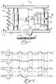
- Fig. 2 of the drawingswhich shows in simplified fashion the different damping forces 42, 44 respectively produced in a system, such as the system 10 of Fig. 1, when damper 18 is switched (i.e., caused to undergo changes in its damping state) in accordance with the dictates of standard and modified versions, respectively, of the control policy predicated upon the sign of the product of the absolute velocity 46 of supported member 12 times the relative velocity 48 of members 12, 13.
- Standard implementation of the aforesaid control policycauses generation of damping forces 42, which are proportional to absolute velocity 46, in those time intervals A, C, E, G, I and K when the product of the absolute velocity 46 and the relative velocity 48 is greater than zero, i.e., is positive or plus.
- damping forces 42are proportional to absolute velocity 46, in those time intervals A, C, E, G, I and K when the product of the absolute velocity 46 and the relative velocity 48 is greater than zero, i.e., is positive or plus.
- the damperIn the other illustrated time intervals, wherein the aforesaid product is less than zero, the damper is in its "off" state and the damping forces are of preselected relatively low magnitude (illustratively zero).
- abrupt changes or discontinuities in damping forces 42occur at the end of time interval C and at the commencement of time intervals G and K. These force discontinuities coincide with "zero crossings," i.e., changes in the sign of the relative velocity 48.
- valve 28 of the damperundergoes an abrupt transition from its prior substantially fully open condition to its substantially fully closed condition, causing the abrupt force increases and discontinuities at the outset of the time intervals G and K.
- the indicated force discontinuitiesmay produce undesirable stresses and/or noise in the system.
- the lowermost plot of Fig. 2indicates the changed damping forces 42' that ensue when the previously described standard control policy is modified so as to delay changes in the damping state of damper 18 until absolute velocity 46 is zero or of other preselected relatively small magnitude.
- the damping forces 42' generated in time intervals A, E and Iare the same as the forces 42 in such time periods.
- the forces 42' which began to be generated in time interval Ccontinue to be generated during and throughout time interval D, and no damping forces whatsoever are generated during time intervals G and K.
- the discontinuities in the damper force 42 arising from use of the standard version of the control policytherefore do not occur in the damping force 42' generated pursuant to the modified version of such control policy.
- the modified control policyneed not always defer all state changes of damper 18. It may instead be so designed as to defer only a preselected percentage of the state changes, or only those in which the state change is from on to off, or from off to on, etc., in which case not all of the force discontinuities will be eliminated.
- Fig. 3 of the drawingsis a simplified graphic representation of a system of the latter type, i.e., one in which there are considerably less zero crossings of the absolute velocity 50 than of the relative velocity 52.
- damper 18is in its off state and no significant damping forces are generated in the time intervals B, D, F, H, J, L, N and P.
- damper 18In time intervals A, C, E, G, I, K, M and O, damper 18 is in its on state and generates damping forces which are proportional to absolute velocity 50. Except at the commencement of time intervals A and G and at the end of time interval O, at each of which there is a zero crossing of absolute velocity 50, the damping force 54 in each of the latter time intervals is characterized by an initial abrupt force increase and a final abrupt force decrease. As is indicated by the force curves 56 in Fig. 3, the abruptness of these transitional force changes can be significantly reduced by limiting to a preselected maximum magnitude the rate at which the adjustably variable damper valve 28 undergoes adjustment, and thus the rate of change of the damping coefficient of damper 18. Fig.
- Summer 92also receives, from a strain gauge or other suitable sensor 94 associated with damper 18, input signals that are proportional to the negative of the damping forces then being produced by the damper.
- Device 92sums the aforesaid inputs to create an error signal which is representative of the control policy dictated change in the damping force. This error signal is transmitted to logic device 90. If the error signal is no greater than a preselected magnitude, in an absolute value sense, a command from logic device 90 causes the valve command signal at terminal 80 of switch 82 to be transmitted via switch terminal 84 directly to the combination valve actuator 28' of damper 18'.
- device 90If the error signal received by it is greater than the preselected magnitude, device 90 causes the valve command signal output from switch 82 to device 28' to be via terminal 86 and a low pass filter 96, the break frequency and order of which are such as to "smooth" (i.e., reduce the rate of change of) the valve command signals sufficiently as to prevent the production by damper force discontinuities of objectionable magnitude.
- the error signal transmitted by summer 92 to logic device 90again becomes less than the preselected magnitude, device 90 returns switch 82 to the condition in which its output again is from terminal 84.
- the filtered output signals of filter 96may also be directed, via a gain device 98, to summer 92. Such signals could then be used, in lieu of those generated by sensor 94, to create the signal used by logic device 90 to cause the input of switch 82 to again be directed to terminal 84.
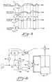
- Results comparable to those described above and illustrated by the damping forces 56 of Fig. 3may alternatively be achieved by providing a bypass flow path, of preselected size, that provides limited communication across valve 28 and thus between variable volume damper chambers 26, 26' even when valve 28 is fully closed.
- a bypass flow pathof preselected size
- branch 30'designates a branch of the circuit 30 interconnecting damper chambers 26, 26'.
- Branch 30'contains a restriction 100, which may be of either a fixed or an adjustably variable type, and extends in parallel relationship to the main part of the circuit 30 containing valve 28.
- C onis the damping coefficient attributable to the restriction by valve 28, when damper 18 is in its "on" state, of fluid flow through the main part of fluid circuit 30.
- Fig. 8is a plot of the normalized "jerk" (i.e., the derivative of acceleration of a supported member, such as member 12) against the on-state damping ratio ⁇ on for mounting systems having a passive damper, a continuously variable semiactive damper not having a parallel flow path, and for a plurality of continuously variable semiactive dampers containing bypass flow paths having different values of ⁇ p .
- the curve 1is for the Passive damper.
- the curve 2is illustrative of that produced by a conventional continuously variable semiactive damper having no parallel flow path and a very high value of ⁇ p .
- Curves 3-6represent semiactive damper systems in which ⁇ p has values of 1.0, 0.75, 0.5 and 0.25, respectively.
- ⁇ phas values of 1.0, 0.75, 0.5 and 0.25, respectively.
- the absolute velocity 50, the relative velocity 52, and the damping force 54are the same as those respectively designated by the corresponding numerals in Fig. 3.
- the other damping forces 68 shown in Fig. 4are produced by another modified version of the damper control policy based upon the sign of the product of the absolute and relative velocities.
- the damping coefficient of damper 18(Fig. 1) is varied so as to cause the damping forces generated at those times when the sign of the aforesaid product is greater than zero, i.e., is plus or positive, to be the smaller of the damping forces proportional to the absolute velocity 50, or the damping forces proportional to the relative velocity 52.
- Fig. 5is a simplified graphic comparison of the damping forces produced in a force attenuating system, such as that of Fig. 1, controlled in accordance with standard and modified versions of the control policy predicated upon the sign of the product of the relative displacement 70 and relative velocity 72 of the supported and supporting members 12, 13.
- damper 18produces damping forces 74 proportional to the relative displacement 70 of members 12, 13 in those time intervals A, C, E and G when the product of the relative displacement and relative velocity 70, 72 is less than zero, i.e., is of negative sign.
- thiscan be determined by monitoring the vertical displacement of member 13, either by use of data derived from that produced by accelerometer sensor 40, or by use of some other type of sensor (not shown) capable of more directly ascertaining the magnitude of the deformation and/or the stored energy of tire 15 and/or other energy-storing member of the system.
- a further alternativeis to defer some or all of the damper state changes until the stored energy of the deformable energy-storing system member is no greater than a preselected magnitude, or until the appropriate system motion parameter (e.g., absolute velocity or relative displacement) of the system is no greater than a preselected low magnitude, whichever first occurs.
- a preselected magnitudee.g., absolute velocity or relative displacement
Landscapes
- Engineering & Computer Science (AREA)
- General Engineering & Computer Science (AREA)
- Mechanical Engineering (AREA)
- Physics & Mathematics (AREA)
- Acoustics & Sound (AREA)
- Aviation & Aerospace Engineering (AREA)
- Electromagnetism (AREA)
- Vehicle Body Suspensions (AREA)
- Fluid-Damping Devices (AREA)
- Vibration Prevention Devices (AREA)
Description
- A method of operating a continuously variable semiactive damper and such dampers themselves.
- Semiactive dampers, and in some instances control policies for them, according to the preambles of
claims 1 and 3, are disclosed in U.S. Patent Nos. 3,807,678, 3,995,883, 4,468,050, 4,468,739, 4,491,207, 4,696,489 and 4,742,998; as well as in U.S. Patent Application Serial Nos. 06/913,067 filed 29 September 1986, and 06/945,380 filed 22 December 1986, both of which are owned by the assignee of the present Application, and in an article by M.J. Crosby et al, entitled "VIBRATION CONTROL USING SEMIACTIVE FORCE GENERATORS", Transaction of the ASME Paper No. 73 DET 122. - Semiactive dampers may be of the "off/on" type or of the "continuously" or "infinitely" variable type. A damper of the first type is switched, in accordance with the dictates of a suitable control policy, between alternative "on" and "off" damping states or conditions. In its on state, the damping coefficient of the damper is of preselected relatively high magnitude. The term "damping coefficient," as used herein, means the relationship of the damping force generated by the damper to the relative velocity across the damper, which relationship is not necessarily linear. In its off state, the damping coefficient of the damper is of relatively low magnitude. This may be approximately zero, but in many vehicle suspensions should be of a magnitude sufficiently greater than zero as to discourage "wheel hop." A continuously variable semiactive damper is also switched during operation between an off state, wherein its damping coefficient is approximately zero or of other low magnitude, and an on state. However, when a continuously variable damper is in its on state the damping coefficient thereof may be and normally is changed between a large (theoretically infinite) number of different magnitudes. If operated pursuant to a suitable control policy, a continuously variable semiactive damper may be caused to perform, when in its on state, in a manner similar to the hypothetical "sky-hook" damper discussed in the hereinbefore-mentioned Crosby et al article and in U.S. Patent 4,742,998.
- A known control policy for a continuously variable semiactive damper dictates that damper be "on," and that the significant damping forces generated by it be proportional (although not necessarily linearly) to the absolute velocity of the supported member, when the sign of the product of such absolute velocity times the relative velocity between the supported member and the supporting member is positive, i.e., is greater than zero. The policy dictates that the damper be in its off state, wherein the damping coefficient is of preselected low magnitude, when the sign of the aforesaid product is negative, i.e., when the product is less than zero. Generally comparable results may be achieved, particularly at relatively high frequency excitations, by use of an alternative control policy which dictates that damping forces proportional to the relative displacement between the supported and supporting members be produced by the continuously variable semiactive damper at those times when the product of the relative velocity times the relative displacement between the members is less than zero, i.e. when the sign of the product is negative or minus; and that the damping forces be of low magnitude when the aforesaid product is greater than zero, i.e. when its sign is positive or plus.
- Although generally producing good results, vibration attenuating systems having continuously variable semiactive damper means controlled in strict accordance with the control policies of the foregoing or similar types may experience shock forces of significant magnitude at some of the times when the damper is switched between its different damping states or conditions. The aforesaid shocks may stress system components to such an extent as to shorten their usual life, and/or may cause the generation of objectionable noise. The problem of noise generation may be particularly apparent in automobile suspensions or other systems containing a resilient deformable member, such as an automobile tire, that is capable of storing energy upon deformation, and of abruptly releasing its stored energy when allowed to rapidly return toward an undeformed condition.
- EP-A-0 367 949, which belongs to the prior art according to Art. 54(3) EPC describes a continuously variable semiactive damper having first and second variable volume chambers interconnected by a flow path which has an adjustable valve that is adjusted in accordance with a preselected control policy to regulate flow through the flow path.
- The present invention provides an improved control method which reduces the generation of undesirable shock forces and/or noise tending to occur in some vehicle suspension systems, or in other mounting systems, having at least one semiactive damper of the continuously variable type.
- From one aspect the invention consists in a method of operating a continuously variable semiactive damper in a mounting system which includes relatively movable supported and supporting members interconnected by said continuously variable semiactive damper, said damper being switchable between a continuously variable on state and an off state to control a level of a damping force, said method being characterized by:
- said damping force being controlled in accordance with one of the following control policies:
- 1) said damping force of said damper, when in its on state, being selected to have a value which is the lesser of a) a value which is proportional to the absolute velocity of supported member, and b) a value which is proportional to the relative velocity between supported member and supporting member;
- 2) said damping force of said damper, when in its on state, being selected to have a value which is the lesser of a) a value which is proportional to the relative displacement of the supported member and the supporting member, and b) a value which is proportional to the relative velocity of said supported member and supporting member; and
- 3) said damping force of said damper, when in its on state, having a rate of change of the damping coefficient limited to a predetermined maximum rate.
- A continuously variable semiactive damper of a mounting system which includes relatively movable supported and supporting members interconnected by said continuously variable semiactive damper, said damper having first and second variable volume chambers interconnected by a first flow path which has a rapidly adjustable valve that is adjusted in accordance with a preselected control policy to regulate fluid flow through said first path of the circuit, said damper being characterized by:
- a second flow path interconnecting said first and second variable volume chambers, said second flow path being in parallel relationship with said first flow path and having a parallel flow path damping ratio Σp which is defined as a ratio of a damping coefficient Cp of said parallel flow path to a critical damping value, Σp having a value between 0.5 and 1.0.
- Fig.1 is a schematic view of a force attenuating suspension or similar mounting system having continuously variable semiactive damper means controllable in accordance with and suitable for practice of the invention;
- Fig.2 is a simplified graphic comparison of the damping forces producible by a continuously variable semiactive damper in a system, such as the system of Fig.1, operated in accordance with a standard version and a modified version of a first control policy;
- Fig.3 is a simplified graphic comparison of the damper forces produced by the semiactive damper during standard operation and another modified mode of operation thereof,
- Fig. 4 is another simplified graphic comparison of the damper forces produced by the damper when operated in a conventional manner and in another modified manner;
- Fig. 5 is a simplified graphic comparison of the damping forces produced by the semiactive damper when operated in accordance with control policies based upon the product of the relative displacement and the relative velocity of the supported and supporting members;
- Fig. 6 is a schematic representation of alternative control components for a semiactive damper in accordance with the invention; and
- Figs. 7 and 8 are graphic representations of the effects of varying a damping ratio of a semiactive damper.
- The numeral 10 in Fig. 1 designates a two degree of freedom suspension or similar force-attenuating mounting system interconnecting vertically spaced and relatively movable supported and supporting
members 12, 13, respectively. By way of example,members 12, 13 may respectively be body and frame components of an automobile or other motor vehicle that is supported upon a road orsimilar surface 14 by conventional resilientlydeformable tire members 15, only one of which is shown. A primary function of a vehicle suspension system such as system 10 might be to isolate supportedmember 12 insofar as possible from vibratory and/or other forces transmitted to member 13 by such things as road-surface irregularities, engine disturbances, etc. The designations X, X1 respectively designate the absolute vertical displacement and the absolute velocity of supportedmember 12, it being arbitrarily indicated that these are positive when in an upward direction and thus are negative when in a downward direction. The same sign convention and the letters Y, Y1 similarly designate the absolute vertical displacement and the absolute velocity of supporting member 13. When system 10 is at rest, X, X1, Y and Y1 are all zero. - System 10 includes compression spring means 16 and semiactive damper means 18 which extend in substantially parallel relationship to each other between
members 12, 13 and are connected to such members. While only a single spring/damper set is shown, more would normally be provided in the typical vehicle suspension system.Damper assembly 18 is illustratively of the hydraulic piston and cylinder type. The piston rod 20 andcylinder 22 ofdamper 18 are secured to respective ones of the supported and supportingmembers 12, 13 by suitable connectors that illustratively includedeformable bushing members 24 formed of elastomer or similar resilient compliant material. Relative vertical movement betweenmembers 12, 13 causes relative vertical movement between rod 20 andcylinder 22, which in turn displaces hydraulic fluid betweenvariable volume chambers 26, 26' ofdamper 18 via an electrically or otherwise rapidlyadjustable control valve 28 forming part of ahydraulic circuit 30 interconnecting such chambers. Rod 20 ofdamper 18 preferably and illustratively extends through both of thecylinder chambers 26, 26' such that the amount of fluid displaced between the chambers is the same irrespective of whether the displacement is produced by compression or by extension of the assembly. This eliminates the need for an accumulator or the like (not shown) in association withdamper 18. Damper 18 is of the "continuously variable" type. It is rapidly switchable between an "off" damping state or condition in which the damping coefficient of the damper is of relatively low magnitude (which in some cases is approximately zero), and an "on" state wherein the damping coefficient of the damper may be caused to be of any desired ones of a large (theoretically infinite) number of relatively high magnitudes. Changes in the damping state ofdamper 18 result from control signals that are imparted to the actuator (not separately shown) of itsvalve 28 and that cause the valve to throttle or restrict fluid flow through the valve to the extent indicated by the signals.Valve 28 may be of mechanical, electrorheological or any other type capable of rapid operation in the foregoing manner.- The control signals for controlling
valve 28 are illustratively electrical ones produced by anelectronic controller 32 that operates pursuant to a preselected control policy and input data received from selected ones of a plurality ofmotion sensors members 12, 13.Sensors 34, 36 directly detect relative displacements and relative velocities of supported and supportingmembers 12, 13.Sensors member 12 and supporting member 13, which accelerations can be utilized by such sensors and/or bycontroller 32 to derive displacement, absolute velocity and/or relative velocity data. Since the data produced bysensors 34, 36 can also be derived from the data produced byacceleration sensors Controller 32 is preprogrammed so as to operate in accordance with a standard modified version of any preselected one of a plurality of semiactive damper control policies. One known control policy is based upon the sign of the product of the relative velocity (X1 - Y1) between the supported and supporting members times the absolute velocity (X1) of the supported member. More specifically, the standard version of the control policy dictates that the damping coefficient of the damper be approximately zero or of other preselected relatively low magnitude when

controller 32 of Fig. 1 may obtain the necessary data with respect to relative velocity fromsensor 36 or may derive all of the necessary data from that supplied bysensors controller 32, in its standard or modified form, is based upon the sign of the product of the relative velocity (X1 - Y1) of the supported and supporting members times the relative displacement (X - Y) of such members. The standard version of this policy dictates that the damping coefficient ofdamper 18 be approximately zero or of other preselected relatively low magnitude when

sensors 34, 36 or, alternatively, may be derived from the data produced byacceleration sensors - Utilization of the foregoing control policies in their standard forms may in certain situations result in the production of undesirable system shock forces and/or noise. One such situation is illustrated in Fig. 2 of the drawings which shows in simplified fashion the different damping
forces 42, 44 respectively produced in a system, such as the system 10 of Fig. 1, whendamper 18 is switched (i.e., caused to undergo changes in its damping state) in accordance with the dictates of standard and modified versions, respectively, of the control policy predicated upon the sign of the product of the absolute velocity 46 of supportedmember 12 times therelative velocity 48 ofmembers 12, 13. Standard implementation of the aforesaid control policy causes generation of dampingforces 42, which are proportional to absolute velocity 46, in those time intervals A, C, E, G, I and K when the product of the absolute velocity 46 and therelative velocity 48 is greater than zero, i.e., is positive or plus. In the other illustrated time intervals, wherein the aforesaid product is less than zero, the damper is in its "off" state and the damping forces are of preselected relatively low magnitude (illustratively zero). It will be noted that abrupt changes or discontinuities in dampingforces 42 occur at the end of time interval C and at the commencement of time intervals G and K. These force discontinuities coincide with "zero crossings," i.e., changes in the sign of therelative velocity 48. Immediately prior to the end of time interval C, generation of substantial dampingforces 42 bydamper 18 was dictated by the standard control policy, and such forces were being produced. In order to produce these damping forces when, as in time interval C, therelative velocity 48 was never large and was becoming increasingly smaller, the control signals directed todamper valve 28 caused it to throttle or restrict the fluid flow to an increasing extent which became maximum asrelative velocity 48 reached approximately zero. Asrelative velocity 48 passed through zero, the standard control policy dictated that the damping forces be zero or of other low magnitude.Valve 28 therefore is caused to undergo abrupt transition from its prior condition, wherein it is substantially completely "closed" and provides maximum resistance to fluid flow, to a condition wherein it is substantially fully "open" and provides minimum resistance to fluid flow. This results in the indicated discontinuity in and abrupt reduction of dampingforce 42 at the end of time interval C. Similarly, immediately prior to the time intervals G and K, when the absolute velocity 46 and therelative velocity 48 are positive and negative, respectively, the control policy then dictates that no damping forces be produced, as a result of whichdamper valve 28 then occupies its fully "open" condition wherein it provides minimum resistance to fluid flow. As therelative velocity 48 crosses through zero at the outset of each of the time intervals G and K, the control policy dictates thatdamper 18 generate damping forces of substantial magnitude, proportional to the magnitude of absolute velocity 46. In order to generate dampingforces 42 of such magnitude, at a time when therelative velocity 48 is of small magnitude,valve 28 of the damper undergoes an abrupt transition from its prior substantially fully open condition to its substantially fully closed condition, causing the abrupt force increases and discontinuities at the outset of the time intervals G and K. The indicated force discontinuities may produce undesirable stresses and/or noise in the system. - The lowermost plot of Fig. 2 indicates the changed damping forces 42' that ensue when the previously described standard control policy is modified so as to delay changes in the damping state of
damper 18 until absolute velocity 46 is zero or of other preselected relatively small magnitude. Under this modified control policy, the damping forces 42' generated in time intervals A, E and I are the same as theforces 42 in such time periods. However, the forces 42' which began to be generated in time interval C continue to be generated during and throughout time interval D, and no damping forces whatsoever are generated during time intervals G and K. The discontinuities in thedamper force 42 arising from use of the standard version of the control policy therefore do not occur in the damping force 42' generated pursuant to the modified version of such control policy. - The modified control policy need not always defer all state changes of
damper 18. It may instead be so designed as to defer only a preselected percentage of the state changes, or only those in which the state change is from on to off, or from off to on, etc., in which case not all of the force discontinuities will be eliminated. - The above-discussed modified control policy is most suitable for use in systems where there are many more zero crossings of the absolute velocity 46 than of the
relative velocity 48. Substantial deterioration of the vibration attenuating performance of the damper may occur when the system is not of this type. Fig. 3 of the drawings is a simplified graphic representation of a system of the latter type, i.e., one in which there are considerably less zero crossings of theabsolute velocity 50 than of therelative velocity 52. Pursuant to the dictates of the standard version of the control policy utilizing the sign of the product of the absolute velocity times the relative velocity,damper 18 is in its off state and no significant damping forces are generated in the time intervals B, D, F, H, J, L, N and P. In time intervals A, C, E, G, I, K, M and O,damper 18 is in its on state and generates damping forces which are proportional toabsolute velocity 50. Except at the commencement of time intervals A and G and at the end of time interval O, at each of which there is a zero crossing ofabsolute velocity 50, the dampingforce 54 in each of the latter time intervals is characterized by an initial abrupt force increase and a final abrupt force decrease. As is indicated by the force curves 56 in Fig. 3, the abruptness of these transitional force changes can be significantly reduced by limiting to a preselected maximum magnitude the rate at which the adjustablyvariable damper valve 28 undergoes adjustment, and thus the rate of change of the damping coefficient ofdamper 18. Fig. 6 is a schematic representation of one type of apparatus that can be employed to achieve the foregoing result. Components of the Fig. 6 apparatus that are similar to those shown in Fig. 1 are designated by the same reference numeral with the addition of a prime designation. The valve-command signals generated by the controller 32' of Fig. 6 pass along a first path to thedata input terminal 80 of aswitching device 82 having alternatively selectabledata output terminals gain device 88, which then converts them to damper command force signals. The damper command force signals ofdevice 88 are received by alogic device 90, and asummer device 92.Summer 92 also receives, from a strain gauge or othersuitable sensor 94 associated withdamper 18, input signals that are proportional to the negative of the damping forces then being produced by the damper.Device 92 sums the aforesaid inputs to create an error signal which is representative of the control policy dictated change in the damping force. This error signal is transmitted tologic device 90. If the error signal is no greater than a preselected magnitude, in an absolute value sense, a command fromlogic device 90 causes the valve command signal atterminal 80 ofswitch 82 to be transmitted viaswitch terminal 84 directly to the combination valve actuator 28' of damper 18'. If the error signal received by it is greater than the preselected magnitude,device 90 causes the valve command signal output fromswitch 82 to device 28' to be viaterminal 86 and alow pass filter 96, the break frequency and order of which are such as to "smooth" (i.e., reduce the rate of change of) the valve command signals sufficiently as to prevent the production by damper force discontinuities of objectionable magnitude. When the error signal transmitted bysummer 92 tologic device 90 again becomes less than the preselected magnitude,device 90 returns switch 82 to the condition in which its output again is fromterminal 84. As is indicated by phantom lines in Fig. 6, the filtered output signals offilter 96 may also be directed, via again device 98, tosummer 92. Such signals could then be used, in lieu of those generated bysensor 94, to create the signal used bylogic device 90 to cause the input ofswitch 82 to again be directed toterminal 84. - Results comparable to those described above and illustrated by the damping
forces 56 of Fig. 3 may alternatively be achieved by providing a bypass flow path, of preselected size, that provides limited communication acrossvalve 28 and thus between variablevolume damper chambers 26, 26' even whenvalve 28 is fully closed. This is indicated by phantom lines in Fig. 1, wherein the numeral 30' designates a branch of thecircuit 30 interconnectingdamper chambers 26, 26'. Branch 30' contains a restriction 100, which may be of either a fixed or an adjustably variable type, and extends in parallel relationship to the main part of thecircuit 30 containingvalve 28. Con is the damping coefficient attributable to the restriction byvalve 28, whendamper 18 is in its "on" state, of fluid flow through the main part offluid circuit 30. Con relates the damping face produced in the on-state ofdamper 18 to the absolute velocity of the supported member 12 (Fig. 1). Cp is the damping coefficient attributable to restriction of fluid flow through parallel branch 30' of the circuit. If there is no flow throughvalve 28, Cp relates the damping force to the relative velocity. Σon is the on-state damping ratio (i.e., the ratio of Con to the critical damping) related to the on-state damping coefficient Con by the equation
member 12 and K is the stiffness ofspring 16. Σp is the parallel flow path damping ratio (i.e., the ratio of Cp to the critical damping) related to Cp by the equation
- The curve 1 is for the Passive damper. The
curve 2 is illustrative of that produced by a conventional continuously variable semiactive damper having no parallel flow path and a very high value of Σp. Curves 3-6 represent semiactive damper systems in which Σp has values of 1.0, 0.75, 0.5 and 0.25, respectively. As is apparent from a comparison ofcurve 2 and curves 3-6, each of the systems having parallel flow paths experiences less jerk than the conventional semiactive system, and the degree of jerk decreases as the value of Σp decreases. However, as is apparent from the graph of Fig. 7, which is similar to that Fig. 8 except that the abscissa in this instance represents the acceleration ofmember 12, the effectiveness of the semiactive damper (in terms of the degree of "isolation" achieved) also decreases, particularly at the higher values of Σon, as the value of Σp decreases. The preferred value of Σp therefore is a compromise one, which yields significantly reduced jerk without unduly detracting from the isolation ofmember 12, within the range of about 0.5 - 1.0. It will be understood that in providing an Σp value in the foregoing range, any leakage about or acrossvalve 28 should be taken into consideration since it also is in parallel with the valve and acts in the same manner as the flow through by-pass branch 30' ofcircuit 30. - In the graphic representation of Fig. 4, the
absolute velocity 50, therelative velocity 52, and the dampingforce 54 are the same as those respectively designated by the corresponding numerals in Fig. 3. The other dampingforces 68 shown in Fig. 4 are produced by another modified version of the damper control policy based upon the sign of the product of the absolute and relative velocities. In the Fig. 4 modified version of such policy, the damping coefficient of damper 18 (Fig. 1) is varied so as to cause the damping forces generated at those times when the sign of the aforesaid product is greater than zero, i.e., is plus or positive, to be the smaller of the damping forces proportional to theabsolute velocity 50, or the damping forces proportional to therelative velocity 52. The result of this policy is most clearly apparent from the dampingforces 68 in time interval E. Such forces track (i.e., are proportional to) therelative velocity 52 until such time as the relative velocity becomes greater than theabsolute velocity 50.Forces 68 then trackabsolute velocity 50 until such time asrelative velocity 52 again becomes smaller thanabsolute velocity 50. - Fig. 5 is a simplified graphic comparison of the damping forces produced in a force attenuating system, such as that of Fig. 1, controlled in accordance with standard and modified versions of the control policy predicated upon the sign of the product of the
relative displacement 70 and relative velocity 72 of the supported and supportingmembers 12, 13. In accordance with the dictates of the standard control policy,damper 18 produces dampingforces 74 proportional to therelative displacement 70 ofmembers 12, 13 in those time intervals A, C, E and G when the product of the relative displacement andrelative velocity 70, 72 is less than zero, i.e., is of negative sign. The other damping force 76 of Fig. 5 is that produced by utilization of a modified control policy in which all switching of the on/off states ofdamper 18 is deferred untilrelative displacement 70 is at or near zero. The modified policy produces damping forces only in time intervals A and G, and not in time intervals C and E. As in the case of the control policy predicated upon the product of the absolute velocity of the supported member times the relative velocity of the supported and supportingmembers 12, 13, another possible modification of the control policy predicated upon the product of the relative displacement and the relative velocity of the supported and supportingmembers 12, 13 would be to cause the damping forces to be the smaller of those proportional to the relative displacement ofmembers 12, 13, or those proportional to the relative velocity ofmembers 12, 13. - In those modified control policies wherein state changes of
damper 28 are deferred until the absolute velocity of supportedmember 12 is at or near zero, or until the relative displacement of supported and supportingmembers 12, 13 is at or near zero, the delay in state change does not necessarily have to occur at every such "zero crossing." Thus, by suitable programming ofcontroller 32, the delays in state changes ofdamper 18 can be caused to occur only when the change is from a lower damping state to a higher damping state, or from a higher damping state to a lower damping state, etc. Modifications of the standard control policies frequently entail a compromise between system performance, on the one hand, and reduction of undesirable system shocks and noise, on the other hand. As a general rule, therefore, it is desirable to depart from the standard control policies only insofar as might be necessary to eliminate objectionable noise, jerks or shocks in the system. - It has been ascertained that the problem of noise generation in a conventional vehicle suspension system, such as that schematically shown in Fig. 1 and which includes a resilient
deformable tire member 15 in series with the illustrateddamper 18, is affected by the condition of the tire. Objectionable noise is particularly likely to ensue whendamper 18 undergoes a change from a higher damping state to a lower damping state at a time when the magnitude of the tire's compressive deformation, and thus its stored energy, is of substantial magnitude. When in a high damping state,damper 18 transmits much of the load force of supportedsuspension member 12 to supporting member 13. This load force, as well as that of member 13, is transmitted viawheel 23 andaxle 25 to tire 15, as a result of which the tire compressively deforms and stores energy. Abrupt reduction in the damping coefficient ofdamper 18, such as would occur upon change in the damper state from on to off, partially "decouples" supportedsuspension member 12 from suspension member 13. In a typical automobile suspension system the weight ofmember 12 is customarily many times greater than that of member 13. The foregoing "decoupling" therefore greatly reduces the forces tending to maintaintire 15 in a compressively deformed, energy-storing condition. Consequently, the tire undergoes rapid return movement to an undeformed condition and abruptly transmits a substantial portion of its stored energy, viawheel 23 andaxle 25, to member 13. This causes "ringing" and "bouncing" of the aforesaid components and accompanying generation of objectionable "thumping" noise. If the particular system contains other resiliently deformable members in series with the damper, such as thecompliant rubber bushings 24 shown in the system 10 of Fig. 1, these also may occasion or contribute to the production of objectionable shock forces and/or noise if the damper state is abruptly changed while such members are in a deformed energy-storing condition. - The aforesaid undesirable results can be eliminated, or at least minimized, by utilization of either of the modified versions of the control policies illustrated in Figs. 2 and 5, and which defer damper state changes, or at least changes from an on state to an off state, until the absolute velocity (in the case of the Fig. 2 policy) or the relative displacement (in the case of the Fig. 5 policy) is of zero or other preselected relatively low magnitude. An alternative approach is to defer all or at least some of the damper state changes until the magnitude of the deformation and thus the stored energy of
tire 15, and/or of some other deformable energy-storing member within the system, is no greater than some preselected low magnitude. In the case oftire 15, this can be determined by monitoring the vertical displacement of member 13, either by use of data derived from that produced byaccelerometer sensor 40, or by use of some other type of sensor (not shown) capable of more directly ascertaining the magnitude of the deformation and/or the stored energy oftire 15 and/or other energy-storing member of the system. - A further alternative is to defer some or all of the damper state changes until the stored energy of the deformable energy-storing system member is no greater than a preselected magnitude, or until the appropriate system motion parameter (e.g., absolute velocity or relative displacement) of the system is no greater than a preselected low magnitude, whichever first occurs.


Claims (4)
- A method of operating a continuously variable semiactive damper (18) in a mounting system (10) which includes relatively movable supported (12) and supporting (13) members interconnected by said continuously variable semiactive damper (18), said damper (18) being switchable between a continuously variable on state and an off state to control a level of a damping force, said method being characterized by:
said damping force being controlled in accordance with one of the following control policies:1) said damping force of said damper (18), when in its on state, being selected to have a value which is the lesser of a) a value which is proportional to the absolute velocity of supported member (12), and b) a value which is proportional to the relative velocity between supported member (12) and supporting member (13);2) said damping force of said damper (18), when in its on state, being selected to have a value which is the lesser of a) a value which is proportional to the relative displacement of the supported member (12) and the supporting member (13), and b) a value which is proportional to the relative velocity of said supported member (12) and supporting member (13); and3) said damping force of said damper (18), when in its on state, having a rate of change of the damping coefficient limited to a predetermined maximum rate. - The method of Claim 1 being further characterized by said damper (18) being of a fluid type, and the system including an adjustable valve (28) for restricting, to an adjustably variable degree, fluid flow across the damper such that the limiting of the rate of change of the damping coefficient includes limiting the rate of adjustment of the valve (28).
- A continuously variable semiactive damper (18) for a mounting system (10) which includes relatively movable supported (12) and supporting (13) members interconnected by said continuously variable semiactive damper (18), said damper (18) having first (26) and second (26') variable volume chambers interconnected by a first flow path (30) which has a rapidly adjustable valve (28) that is adjusted in accordance with a preselected control policy to regulate fluid flow through said first path of the circuit,a second flow path (30') interconnecting said first (26) and second (26') variable volume chambers, said second flow path (30') being in parallel relationship with said first flow path (30), said damper (18) being characterized by: a parallel flow path damping ratio Σp which is defined as a ratio of a damping coefficient Cp of said parallel flow path to a critical damping value, Σp having a value between 0.5 and 1.0.
- The damper of Claim 3 being further characterized by a spring member (16) and said parallel flow path damping ratio Σp being defined by the equation


Applications Claiming Priority (3)
| Application Number | Priority Date | Filing Date | Title |
|---|---|---|---|
| US310109 | 1989-02-10 | ||
| US07/310,109US4887699A (en) | 1989-02-10 | 1989-02-10 | Vibration attenuating method utilizing continuously variable semiactive damper |
| EP90301237AEP0382480B1 (en) | 1989-02-10 | 1990-02-06 | Vibration attenuating method utilizing continuously variable semiactive damper |
Related Parent Applications (1)
| Application Number | Title | Priority Date | Filing Date |
|---|---|---|---|
| EP90301237.5Division | 1990-02-06 |
Publications (3)
| Publication Number | Publication Date |
|---|---|
| EP0538965A2 EP0538965A2 (en) | 1993-04-28 |
| EP0538965A3 EP0538965A3 (en) | 1993-05-19 |
| EP0538965B1true EP0538965B1 (en) | 1996-10-23 |
Family
ID=23201021
Family Applications (2)
| Application Number | Title | Priority Date | Filing Date |
|---|---|---|---|
| EP90301237AExpired - LifetimeEP0382480B1 (en) | 1989-02-10 | 1990-02-06 | Vibration attenuating method utilizing continuously variable semiactive damper |
| EP92204114AExpired - LifetimeEP0538965B1 (en) | 1989-02-10 | 1990-02-06 | Vibration attenuating method utilizing continuously variable semiactive damper |
Family Applications Before (1)
| Application Number | Title | Priority Date | Filing Date |
|---|---|---|---|
| EP90301237AExpired - LifetimeEP0382480B1 (en) | 1989-02-10 | 1990-02-06 | Vibration attenuating method utilizing continuously variable semiactive damper |
Country Status (5)
| Country | Link |
|---|---|
| US (1) | US4887699A (en) |
| EP (2) | EP0382480B1 (en) |
| JP (1) | JPH02246817A (en) |
| DE (2) | DE69003830T2 (en) |
| ES (1) | ES2093184T3 (en) |
Cited By (1)
| Publication number | Priority date | Publication date | Assignee | Title |
|---|---|---|---|---|
| DE102018203733A1 (en) | 2018-03-13 | 2019-09-19 | Audi Ag | motor vehicle |
Families Citing this family (109)
| Publication number | Priority date | Publication date | Assignee | Title |
|---|---|---|---|---|
| US5845896A (en)* | 1995-09-08 | 1998-12-08 | Riad; Fawzy | Counter balanced suspension |
| DE3837863C2 (en)* | 1988-11-08 | 1995-02-09 | Daimler Benz Ag | Suspension system for vehicles |
| DE3888849T2 (en)* | 1988-12-22 | 1994-10-13 | Moog Inc | VIBRATION DAMPING MACHINE BEARING. |
| EP0403803B1 (en)* | 1989-06-20 | 1992-07-01 | AUGUST BILSTEIN GMBH & CO. KG | Semi-active suspension |
| DE3935376A1 (en)* | 1989-10-24 | 1991-04-25 | Bosch Gmbh Robert | METHOD AND DEVICE FOR CHASSIS CONTROL |
| JP2908496B2 (en)* | 1990-02-14 | 1999-06-21 | 株式会社デンソー | Shock absorber damping force control device |
| US5052510A (en)* | 1990-02-16 | 1991-10-01 | Noise Cancellation Technologies, Inc. | Hybrid type vibration isolation apparatus |
| US5222759A (en)* | 1990-02-27 | 1993-06-29 | Robert Bosch Gmbh | Apparatus for active control of body motions in motor vehicles |
| JPH0490916A (en)* | 1990-08-06 | 1992-03-24 | Honda Motor Co Ltd | Control method of suspension device for vehicle |
| US5265704A (en)* | 1990-08-07 | 1993-11-30 | Robert Bosch Gmbh | Apparatus for damping courses of motion |
| SE466796B (en)* | 1990-08-10 | 1992-04-06 | Saab Scania Ab | SPRING SYSTEM WITH CONDITIONING RESONANCE DIMENSION AND PROCEDURE FOR REGULATING THE SPRING SYSTEM |
| JP3037735B2 (en)* | 1990-10-26 | 2000-05-08 | マツダ株式会社 | Vehicle suspension device |
| DE4035314A1 (en)* | 1990-11-07 | 1992-05-14 | Bosch Gmbh Robert | METHOD FOR SEMIAACTIVELY REGULATING A CHASSIS |
| DE4114305A1 (en)* | 1990-12-08 | 1992-06-11 | Fichtel & Sachs Ag | SHUT-OFF VALVE DEVICE |
| DE4138171A1 (en)* | 1991-02-14 | 1992-08-20 | Bilstein August Gmbh Co Kg | METHOD FOR REGULATING A SEMIAACTIVE CHASSIS |
| DE4109471A1 (en)* | 1991-03-22 | 1992-09-24 | Bosch Gmbh Robert | SHOCK ABSORBER |
| DE4112004A1 (en)* | 1991-04-12 | 1992-10-15 | Bosch Gmbh Robert | CHASSIS CONTROL SYSTEM |
| DE4216433C2 (en)* | 1991-05-17 | 1998-03-12 | Atsugi Unisia Corp | Method for controlling a shock absorber with variable damping characteristics and motor vehicle with a correspondingly controlled shock absorber |
| FR2680848B1 (en)* | 1991-08-29 | 1995-03-17 | Aerospatiale Ste Nat Indle | METHOD AND DEVICE FOR FILTERING THE VIBRATORY EXCITATIONS TRANSMITTED BETWEEN TWO PARTS, IN PARTICULAR BETWEEN THE ROTOR AND THE FUSELAGE OF A HELICOPTER. |
| JPH0648133A (en)* | 1991-10-03 | 1994-02-22 | Unisia Jecs Corp | Vehicle suspension |
| US5276622A (en)* | 1991-10-25 | 1994-01-04 | Lord Corporation | System for reducing suspension end-stop collisions |
| DE4136104A1 (en)* | 1991-11-02 | 1993-05-06 | Fichtel & Sachs Ag, 8720 Schweinfurt, De | METHOD FOR INFLUENCING A SPRING AND DAMPING SUPPORT SYSTEM BETWEEN CHASSIS AND ASSEMBLY OF A VEHICLE AND SUPPORT SYSTEM FOR IMPLEMENTING THIS PROCESS |
| DE4136261A1 (en)* | 1991-11-04 | 1993-05-06 | Fichtel & Sachs Ag, 8720 Schweinfurt, De | METHOD AND DEVICE FOR THE OPERATIONAL INFLUENCING OF DAMPING ASSEMBLIES OF A VEHICLE |
| US5276623A (en)* | 1991-11-27 | 1994-01-04 | Lord Corporation | System for controlling suspension deflection |
| JP3342719B2 (en)* | 1992-02-03 | 2002-11-11 | トキコ株式会社 | Suspension control device |
| FR2687201B1 (en)* | 1992-02-10 | 1995-07-07 | Siemens Automotive Sa | METHOD OF CONTROLLING A SHOCK ABSORBER AND ITS USE IN A SUSPENSION DEVICE FOR A MOTOR VEHICLE. |
| NL9200301A (en)* | 1992-02-18 | 1993-09-16 | Koni Bv | VEHICLE DAMPER CONTROL. |
| JP2646414B2 (en)* | 1992-02-21 | 1997-08-27 | キヤノン株式会社 | Semiconductor manufacturing equipment |
| DE4242912B4 (en)* | 1992-12-18 | 2007-01-18 | Robert Bosch Gmbh | Method for controlling and / or controlling a motor vehicle chassis |
| US5398785A (en)* | 1993-01-11 | 1995-03-21 | Regeants Of The University Of California | Semiactive control apparatus for damping vibrations of a body |
| JPH06247117A (en)* | 1993-02-23 | 1994-09-06 | Unisia Jecs Corp | Vehicle suspension device |
| US5595372A (en)* | 1993-03-11 | 1997-01-21 | The Board Of Regents Of The University Of Oklahoma | Semi-active vibration mitigation assembly |
| US6032770A (en)* | 1993-04-12 | 2000-03-07 | Raytheon Company | Low force actuator for suspension control |
| US5390121A (en)* | 1993-08-19 | 1995-02-14 | Lord Corporation | Banded on-off control method for semi-active dampers |
| JPH0796727A (en)* | 1993-09-28 | 1995-04-11 | Toyota Motor Corp | Electric control device for shock absorber |
| US5660255A (en)* | 1994-04-04 | 1997-08-26 | Applied Power, Inc. | Stiff actuator active vibration isolation system |
| FR2722265B1 (en)* | 1994-07-06 | 1996-08-23 | Gec Alsthom Transport Sa | SEMI-ACTIVE SHOCK ABSORBER |
| KR100399812B1 (en) | 1994-10-11 | 2003-12-01 | 가부시키가이샤 니콘 | Vibration Prevention Device for Stage |
| US5984062A (en)* | 1995-02-24 | 1999-11-16 | Bobrow; James E. | Method for controlling an active truss element for vibration suppression |
| US5975508A (en)* | 1995-09-06 | 1999-11-02 | Applied Power Inc. | Active vehicle seat suspension system |
| US5603387A (en)* | 1995-09-06 | 1997-02-18 | Applied Power, Inc. | Active vehicle suspension system |
| US5794909A (en)* | 1996-09-16 | 1998-08-18 | Minus K Technology, Inc. | Auto-adjust apparatus for a vibration isolation system |
| US5810125A (en)* | 1996-09-19 | 1998-09-22 | Stidd Systems, Inc. | Active shock-absorbing seating system |
| WO1998022727A1 (en)* | 1996-11-21 | 1998-05-28 | Advanced Fluid Systems Limited | Flow-control valve and damper |
| US6070681A (en)* | 1997-06-13 | 2000-06-06 | Lord Corporation | Controllable cab suspension |
| US6131709A (en)* | 1997-11-25 | 2000-10-17 | Lord Corporation | Adjustable valve and vibration damper utilizing same |
| US6049746A (en) | 1998-04-01 | 2000-04-11 | Lord Corporation | End stop control method |
| US6053269A (en)* | 1998-08-13 | 2000-04-25 | The Board Of Regents Of The University Of Oklahoma | Vehicle/bridge vibration mitigation assembly |
| US6115658A (en) | 1999-01-04 | 2000-09-05 | Lord Corporation | No-jerk semi-active skyhook control method and apparatus |
| US7219449B1 (en) | 1999-05-03 | 2007-05-22 | Promdx Technology, Inc. | Adaptively controlled footwear |
| US6311110B1 (en) | 1999-06-17 | 2001-10-30 | Lord Corporation | Adaptive off-state control method |
| US6805337B1 (en)* | 2000-03-02 | 2004-10-19 | Omnitek Research & Development, Inc. | Apparatus for isolation of payloads with low transmissibility |
| US6352143B1 (en) | 2000-03-09 | 2002-03-05 | Bridgestone/Firestone, Inc. | Vibration damping system using a hydraulic damper with a field responsive fluid control |
| WO2001081115A1 (en) | 2000-04-20 | 2001-11-01 | Lord Corporation | Automatic calibration method for a suspended seat system |
| US6394238B1 (en)* | 2000-05-25 | 2002-05-28 | Husco International, Inc. | Regenerative suspension for an off-road vehicle |
| US6543589B2 (en) | 2000-05-26 | 2003-04-08 | Richard D. Anderson | Method for controlling the damping force of a damper |
| US6467748B1 (en)* | 2000-09-05 | 2002-10-22 | Deere & Company | Hydraulic circuit for active suspension system |
| DE10112159A1 (en)* | 2001-03-14 | 2002-09-19 | Wabco Gmbh & Co Ohg | Method and device for determining the driving condition of vehicles in the event of failure or lack of a speed sensor |
| EP1247665B1 (en)* | 2001-04-04 | 2006-03-22 | STMicroelectronics S.r.l. | Method and apparatus for controlling a vehicle suspension system based on sky hook approach |
| DE50211806D1 (en)* | 2001-05-09 | 2008-04-17 | Continental Ag | Method for regulating the damper current for electrically adjustable dampers |
| US6752250B2 (en)* | 2001-09-27 | 2004-06-22 | Northrop Grumman Corporation | Shock, vibration and acoustic isolation system |
| CA2473140C (en)* | 2002-01-11 | 2010-05-04 | John A. Laplante | Semi-active shock absorber control system |
| DE10203554A1 (en)* | 2002-01-29 | 2003-08-14 | Continental Ag | Adjustable damper for a motor vehicle |
| AU2003225660A1 (en)* | 2002-03-06 | 2003-09-22 | Vssl Commercial, Inc. | Active suspension for a marine platform |
| US6834736B2 (en)* | 2002-12-17 | 2004-12-28 | Husco International, Inc. | Active vehicle suspension with a hydraulic spring |
| US6695102B1 (en) | 2002-12-31 | 2004-02-24 | Lord Corporation | Magnetorheological twin-tube damping device |
| US7942248B2 (en) | 2002-12-31 | 2011-05-17 | Lord Corporation | Adjustable damping control with end stop |
| US7108111B2 (en)* | 2004-10-25 | 2006-09-19 | Enidine Incorporated | Semi-active isolator |
| US20070045067A1 (en) | 2005-08-26 | 2007-03-01 | Husco International, Inc. | Hydraulic circuit with a pilot operated check valve for an active vehicle suspension system |
| US7234386B2 (en) | 2005-08-26 | 2007-06-26 | Husco International, Inc. | Three chamber hydraulic cylinder for an active vehicle suspension with integrated load leveling |
| US20070045069A1 (en)* | 2005-08-26 | 2007-03-01 | Husco International, Inc. | Active vehicle suspension with integrated load leveling |
| FR2890900B1 (en)* | 2005-09-22 | 2007-12-14 | Peugeot Citroen Automobiles Sa | SUSPENSION CONTROL DEVICE, VEHICLE EQUIPPED WITH SAME, METHOD OF OBTAINING AND PROGRAM. |
| US8302456B2 (en) | 2006-02-23 | 2012-11-06 | Asylum Research Corporation | Active damping of high speed scanning probe microscope components |
| US7921973B2 (en)* | 2006-05-31 | 2011-04-12 | Techno-Sciences, Inc. | Adaptive energy absorption system for a vehicle seat |
| US7878312B2 (en)* | 2006-05-31 | 2011-02-01 | University Of Maryland | Adaptive energy absorption system for a vehicle seat |
| US7822522B2 (en)* | 2006-05-31 | 2010-10-26 | Techno-Sciences, Inc. (corporation) | Adaptive energy absorption system for a vehicle seat |
| US7669708B2 (en)* | 2006-08-31 | 2010-03-02 | Martin Engineering Company | Bulk material handling system and control |
| US7556140B2 (en)* | 2006-08-31 | 2009-07-07 | Martin Engineering Company | Bulk material handling system |
| JP4525651B2 (en)* | 2006-09-15 | 2010-08-18 | トヨタ自動車株式会社 | Vehicle suspension system |
| US8473163B2 (en)* | 2007-02-02 | 2013-06-25 | Techno-Sciences, Inc. | Method of determining impact severity and adaptive impact attenuation |
| US7946163B2 (en)* | 2007-04-02 | 2011-05-24 | Penske Racing Shocks | Methods and apparatus for developing a vehicle suspension |
| US8839920B2 (en) | 2008-04-17 | 2014-09-23 | Levant Power Corporation | Hydraulic energy transfer |
| US8392030B2 (en)* | 2008-04-17 | 2013-03-05 | Levant Power Corporation | System and method for control for regenerative energy generators |
| US8376100B2 (en)* | 2008-04-17 | 2013-02-19 | Levant Power Corporation | Regenerative shock absorber |
| EP2156970A1 (en) | 2008-08-12 | 2010-02-24 | Nederlandse Organisatie voor toegepast- natuurwetenschappelijk onderzoek TNO | Multi-point hydraulic suspension system for a land vehicle |
| US7735838B2 (en)* | 2008-08-20 | 2010-06-15 | Husco International, Inc. | Vehicle suspension with selectable roll stabilization |
| US8196723B1 (en) | 2008-11-14 | 2012-06-12 | Robust Systems Solutions, LLC | Pneumatic damper |
| DE102009008994A1 (en) | 2009-02-14 | 2010-08-19 | Bayerische Motoren Werke Aktiengesellschaft | Method for regulating damping force of infinitely variable semi-active damper between body and chassis of motor vehicle, involves utilizing relative speed of damper piston rod for damper pipe as reference variable |
| WO2010113329A1 (en) | 2009-03-31 | 2010-10-07 | トヨタ自動車株式会社 | Damping force controller |
| EP2582976B1 (en) | 2010-06-16 | 2019-08-21 | ClearMotion, Inc. | Integrated energy generating damper |
| US8205741B2 (en) | 2010-08-06 | 2012-06-26 | Martin Engineering Company | Method of adjusting conveyor belt scrapers and open loop control system for conveyor belt scrapers |
| EP2574819B1 (en)* | 2011-09-30 | 2014-04-23 | Siemens Aktiengesellschaft | Speed-proportional active oscillation attenuator |
| US9174508B2 (en) | 2013-03-15 | 2015-11-03 | Levant Power Corporation | Active vehicle suspension |
| US9702349B2 (en) | 2013-03-15 | 2017-07-11 | ClearMotion, Inc. | Active vehicle suspension system |
| WO2014152482A2 (en) | 2013-03-15 | 2014-09-25 | Levant Power Corporation | Multi-path fluid diverter valve |
| EP3626485B1 (en) | 2013-03-15 | 2024-05-29 | ClearMotion, Inc. | Active vehicle suspension improvements |
| US9855814B2 (en) | 2013-04-23 | 2018-01-02 | ClearMotion, Inc. | Active suspension with structural actuator |
| US9383388B2 (en) | 2014-04-21 | 2016-07-05 | Oxford Instruments Asylum Research, Inc | Automated atomic force microscope and the operation thereof |
| CN104401197B (en)* | 2014-09-16 | 2018-12-14 | 青岛理工大学 | Self-powered system of hybrid truck |
| US9702424B2 (en) | 2014-10-06 | 2017-07-11 | ClearMotion, Inc. | Hydraulic damper, hydraulic bump-stop and diverter valve |
| JP6499417B2 (en)* | 2014-10-27 | 2019-04-10 | Kyb株式会社 | Damper control device |
| CN105526305B (en)* | 2016-01-27 | 2017-12-05 | 潍柴动力股份有限公司 | A kind of system and method for being used to suppress marine diesel oil machine vibration |
| EP3753102B1 (en)* | 2018-02-13 | 2024-01-17 | FCX Solar LLC | Solar tracker system |
| US11440366B1 (en)* | 2018-10-03 | 2022-09-13 | ClearMotion, Inc. | Frequency dependent pressure and/or flow fluctuation mitigation in hydraulic systems |
| CN110185311B (en)* | 2019-05-29 | 2020-11-13 | 长安大学 | A damping adjustable vibration reduction and noise reduction device |
| US11124272B2 (en)* | 2019-11-11 | 2021-09-21 | Steering Solutions Ip Holding Corporation | System and method for vibration cancellation |
| US12128726B2 (en) | 2021-01-28 | 2024-10-29 | Volvo Car Corporation | Rear damper adjustment |
| US12005752B2 (en)* | 2021-01-28 | 2024-06-11 | Volvo Car Corporation | Limiting vehicle damper jerk |
| CN115111302B (en)* | 2022-07-28 | 2024-03-01 | 安徽工程大学 | Damping device for electric drive axle controller |
Family Cites Families (27)
| Publication number | Priority date | Publication date | Assignee | Title |
|---|---|---|---|---|
| US2235488A (en)* | 1936-12-22 | 1941-03-18 | Mercier Jean | Shock-absorbing device |
| BE550278A (en)* | 1955-08-23 | |||
| FR1336186A (en)* | 1962-07-09 | 1963-08-30 | Device opposing a resistance to the flow of a fluid that is practically independent of its viscosity, in particular in hydraulic shock absorbers | |
| US3321210A (en)* | 1966-04-12 | 1967-05-23 | Frederick J Harding | Electrically controlled shock absorber system |
| US3420341A (en)* | 1967-10-16 | 1969-01-07 | Jonathan N Keehn | Variable shock absorber |
| US3807678A (en)* | 1972-09-19 | 1974-04-30 | Lord Corp | System for controlling the transmission of energy between spaced members |
| US3826343A (en)* | 1972-12-08 | 1974-07-30 | Conair | Pressure regulator for hydraulic shock absorbers |
| US3995883A (en)* | 1973-11-21 | 1976-12-07 | Lucas Aerospace Limited | Land vehicle wheel suspension arrangements |
| IT1037130B (en)* | 1974-03-22 | 1979-11-10 | Volkswagenwerk Ag | TELESCOPIC SHOCK ABSORBER IN PARTICULAR FOR AUTVEICKLO |
| DE2948605A1 (en)* | 1979-12-03 | 1981-06-11 | Ludwig Dr.-Ing. 7500 Karlsruhe Pietzsch | Vehicle suspension springing system - has lockable spring, forming part of sprung shock absorber, parallel to main spring |
| US4468050A (en)* | 1983-08-15 | 1984-08-28 | Woods Lonnie K | Computer optimized adaptive suspension system |
| US4468739A (en)* | 1981-11-17 | 1984-08-28 | Woods Lonnie K | Computer optimized adaptive suspension system having combined shock absorber/air spring unit |
| US4620619A (en)* | 1982-05-20 | 1986-11-04 | Atsugi Motor Parts Co., Ltd. | Variable-damping-force shock absorber |
| FR2528140B1 (en)* | 1982-06-03 | 1985-10-11 | Messier Hispano Sa | FLUIDIC TYPE SHOCK ABSORBER |
| ES8503803A1 (en)* | 1983-06-29 | 1985-03-01 | Boge Gmbh | Adjustable hydraulic damper apparatus |
| US4491207A (en)* | 1983-07-15 | 1985-01-01 | Lord Corporation | Fluid control means for vehicle suspension system |
| GB2147683B (en)* | 1983-09-24 | 1986-10-01 | Bilstein August Gmbh Co Kg | Shock absorber, with electromagnetically biased pressure responsive valve |
| DE3432465A1 (en)* | 1984-09-04 | 1986-03-13 | Boge Gmbh, 5208 Eitorf | ADJUSTABLE DAMPING VALVE FOR A HYDRAULIC VIBRATION DAMPER |
| JPS61163011A (en)* | 1985-01-14 | 1986-07-23 | Nissan Motor Co Ltd | Electronically controlled shock absorber device |
| US4742998A (en)* | 1985-03-26 | 1988-05-10 | Barry Wright Corporation | Active vibration isolation system employing an electro-rheological fluid |
| DE3524863A1 (en)* | 1985-04-12 | 1986-10-30 | Robert Bosch Gmbh, 7000 Stuttgart | METHOD AND DEVICE FOR CONTROLLING THE SUSPENSION, IN PARTICULAR FOR VEHICLES |
| DE3518503C1 (en)* | 1985-05-23 | 1986-10-23 | Daimler-Benz Ag, 7000 Stuttgart | Device for computer-aided, road-dependent control of dampers of a vehicle suspension |
| US4756549A (en)* | 1985-10-26 | 1988-07-12 | Toyota Jidosha Kabushiki Kaisha | Shock absorber controller |
| DE3610937A1 (en)* | 1986-04-02 | 1987-10-08 | Bosch Gmbh Robert | DEVICE FOR DAMPING MOTION PROCESSES |
| US4809179A (en)* | 1987-01-20 | 1989-02-28 | Ford Motor Company | Control system for motor vehicle suspension unit |
| DE3810638C1 (en)* | 1988-03-29 | 1989-08-10 | Boge Ag, 5208 Eitorf, De | |
| DE3837863C2 (en)* | 1988-11-08 | 1995-02-09 | Daimler Benz Ag | Suspension system for vehicles |
- 1989
- 1989-02-10USUS07/310,109patent/US4887699A/ennot_activeExpired - Lifetime
- 1990
- 1990-02-06ESES92204114Tpatent/ES2093184T3/ennot_activeExpired - Lifetime
- 1990-02-06EPEP90301237Apatent/EP0382480B1/ennot_activeExpired - Lifetime
- 1990-02-06DEDE90301237Tpatent/DE69003830T2/ennot_activeExpired - Fee Related
- 1990-02-06EPEP92204114Apatent/EP0538965B1/ennot_activeExpired - Lifetime
- 1990-02-06DEDE69028995Tpatent/DE69028995T2/ennot_activeExpired - Fee Related
- 1990-02-07JPJP2026253Apatent/JPH02246817A/enactivePending
Cited By (2)
| Publication number | Priority date | Publication date | Assignee | Title |
|---|---|---|---|---|
| DE102018203733A1 (en) | 2018-03-13 | 2019-09-19 | Audi Ag | motor vehicle |
| DE102018203733B4 (en)* | 2018-03-13 | 2020-11-19 | Audi Ag | Motor vehicle |
Also Published As
| Publication number | Publication date |
|---|---|
| DE69003830D1 (en) | 1993-11-18 |
| EP0382480A1 (en) | 1990-08-16 |
| DE69028995T2 (en) | 1997-03-06 |
| US4887699A (en) | 1989-12-19 |
| ES2093184T3 (en) | 1996-12-16 |
| EP0538965A2 (en) | 1993-04-28 |
| EP0538965A3 (en) | 1993-05-19 |
| DE69003830T2 (en) | 1994-04-14 |
| DE69028995D1 (en) | 1996-11-28 |
| EP0382480B1 (en) | 1993-10-13 |
| JPH02246817A (en) | 1990-10-02 |
Similar Documents
| Publication | Publication Date | Title |
|---|---|---|
| EP0538965B1 (en) | Vibration attenuating method utilizing continuously variable semiactive damper | |
| US4936425A (en) | Method of operating a vibration attenuating system having semiactive damper means | |
| US5276623A (en) | System for controlling suspension deflection | |
| US5732370A (en) | Method for controlling motion using a two-stage adjustable damper | |
| EP0262886B1 (en) | Control method and means for vibration attenuating damper | |
| US5276622A (en) | System for reducing suspension end-stop collisions | |
| EP0397488B1 (en) | Wheel assembly suspending | |
| US6032770A (en) | Low force actuator for suspension control | |
| US5004079A (en) | Semi-active damper valve means and method | |
| EP0739766B1 (en) | Method for controlling motion using an adjustable damper | |
| US4765648A (en) | Suspension system for a motor vehicle | |
| Karnopp et al. | Electronically controllable vehicle suspensions | |
| US7321816B2 (en) | Model free semi-active vehicle suspension system | |
| EP0239831B1 (en) | Suspension control method and apparatus | |
| US6115658A (en) | No-jerk semi-active skyhook control method and apparatus | |
| KR100254126B1 (en) | Procedure for semi active regulation of chassis | |
| US5218546A (en) | Frequency shaping method for minimizing impact harshness of suspension system | |
| US4776610A (en) | Short-stroke position transducer for a vehicle suspension system | |
| Jolly et al. | The control of semi-active dampers using relative feedback signals | |
| Satoh et al. | An active suspension employing an electrohydraulic pressure control system | |
| EP0200384A2 (en) | A suspension system for a motor vehicle | |
| Barak | Design and evaluation of an adjustable automobile suspension | |
| Richardson | Adaptive Suspension Damping | |
| JPS6346907A (en) | Air suspension device | |
| JPH01247834A (en) | Hydraulic buffer |
Legal Events
| Date | Code | Title | Description |
|---|---|---|---|
| PUAI | Public reference made under article 153(3) epc to a published international application that has entered the european phase | Free format text:ORIGINAL CODE: 0009012 | |
| PUAL | Search report despatched | Free format text:ORIGINAL CODE: 0009013 | |
| AC | Divisional application: reference to earlier application | Ref document number:382480 Country of ref document:EP | |
| AK | Designated contracting states | Kind code of ref document:A2 Designated state(s):BE DE ES FR GB IT NL SE | |
| AK | Designated contracting states | Kind code of ref document:A3 Designated state(s):BE DE ES FR GB IT NL SE | |
| 17P | Request for examination filed | Effective date:19931104 | |
| 17Q | First examination report despatched | Effective date:19950119 | |
| GRAH | Despatch of communication of intention to grant a patent | Free format text:ORIGINAL CODE: EPIDOS IGRA | |
| RAP1 | Party data changed (applicant data changed or rights of an application transferred) | Owner name:LORD CORPORATION | |
| GRAH | Despatch of communication of intention to grant a patent | Free format text:ORIGINAL CODE: EPIDOS IGRA | |
| GRAA | (expected) grant | Free format text:ORIGINAL CODE: 0009210 | |
| AC | Divisional application: reference to earlier application | Ref document number:382480 Country of ref document:EP | |
| AK | Designated contracting states | Kind code of ref document:B1 Designated state(s):BE DE ES FR GB IT NL SE | |
| ITF | It: translation for a ep patent filed | ||
| REF | Corresponds to: | Ref document number:69028995 Country of ref document:DE Date of ref document:19961128 | |
| REG | Reference to a national code | Ref country code:ES Ref legal event code:FG2A Ref document number:2093184 Country of ref document:ES Kind code of ref document:T3 | |
| ET | Fr: translation filed | ||
| PLBE | No opposition filed within time limit | Free format text:ORIGINAL CODE: 0009261 | |
| 26N | No opposition filed | ||
| REG | Reference to a national code | Ref country code:GB Ref legal event code:IF02 | |
| PGFP | Annual fee paid to national office [announced via postgrant information from national office to epo] | Ref country code:SE Payment date:20030121 Year of fee payment:14 Ref country code:NL Payment date:20030121 Year of fee payment:14 | |
| PGFP | Annual fee paid to national office [announced via postgrant information from national office to epo] | Ref country code:BE Payment date:20030214 Year of fee payment:14 | |
| PGFP | Annual fee paid to national office [announced via postgrant information from national office to epo] | Ref country code:ES Payment date:20030311 Year of fee payment:14 | |
| PGFP | Annual fee paid to national office [announced via postgrant information from national office to epo] | Ref country code:GB Payment date:20040128 Year of fee payment:15 | |
| PG25 | Lapsed in a contracting state [announced via postgrant information from national office to epo] | Ref country code:SE Free format text:LAPSE BECAUSE OF NON-PAYMENT OF DUE FEES Effective date:20040207 Ref country code:ES Free format text:LAPSE BECAUSE OF NON-PAYMENT OF DUE FEES Effective date:20040207 | |
| PGFP | Annual fee paid to national office [announced via postgrant information from national office to epo] | Ref country code:FR Payment date:20040219 Year of fee payment:15 | |
| PG25 | Lapsed in a contracting state [announced via postgrant information from national office to epo] | Ref country code:BE Free format text:LAPSE BECAUSE OF NON-PAYMENT OF DUE FEES Effective date:20040228 | |
| PGFP | Annual fee paid to national office [announced via postgrant information from national office to epo] | Ref country code:DE Payment date:20040331 Year of fee payment:15 | |
| BERE | Be: lapsed | Owner name:*LORD CORP. Effective date:20040228 | |
| PG25 | Lapsed in a contracting state [announced via postgrant information from national office to epo] | Ref country code:NL Free format text:LAPSE BECAUSE OF NON-PAYMENT OF DUE FEES Effective date:20040901 | |
| EUG | Se: european patent has lapsed | ||
| NLV4 | Nl: lapsed or anulled due to non-payment of the annual fee | Effective date:20040901 | |
| PG25 | Lapsed in a contracting state [announced via postgrant information from national office to epo] | Ref country code:IT Free format text:LAPSE BECAUSE OF NON-PAYMENT OF DUE FEES;WARNING: LAPSES OF ITALIAN PATENTS WITH EFFECTIVE DATE BEFORE 2007 MAY HAVE OCCURRED AT ANY TIME BEFORE 2007. THE CORRECT EFFECTIVE DATE MAY BE DIFFERENT FROM THE ONE RECORDED. Effective date:20050206 Ref country code:GB Free format text:LAPSE BECAUSE OF NON-PAYMENT OF DUE FEES Effective date:20050206 | |
| REG | Reference to a national code | Ref country code:ES Ref legal event code:FD2A Effective date:20040207 | |
| PG25 | Lapsed in a contracting state [announced via postgrant information from national office to epo] | Ref country code:DE Free format text:LAPSE BECAUSE OF NON-PAYMENT OF DUE FEES Effective date:20050901 | |
| GBPC | Gb: european patent ceased through non-payment of renewal fee | Effective date:20050205 | |
| PG25 | Lapsed in a contracting state [announced via postgrant information from national office to epo] | Ref country code:FR Free format text:LAPSE BECAUSE OF NON-PAYMENT OF DUE FEES Effective date:20051031 | |
| REG | Reference to a national code | Ref country code:FR Ref legal event code:ST Effective date:20051031 |